EP2650904A2 - Method for manufacturing a roll for roll printing/roll imprinting - Google Patents
Method for manufacturing a roll for roll printing/roll imprinting Download PDFInfo
- Publication number
- EP2650904A2 EP2650904A2 EP11847066.5A EP11847066A EP2650904A2 EP 2650904 A2 EP2650904 A2 EP 2650904A2 EP 11847066 A EP11847066 A EP 11847066A EP 2650904 A2 EP2650904 A2 EP 2650904A2
- Authority
- EP
- European Patent Office
- Prior art keywords
- roll
- exterior
- mixture
- manufacturing
- imprinting
- Prior art date
- Legal status (The legal status is an assumption and is not a legal conclusion. Google has not performed a legal analysis and makes no representation as to the accuracy of the status listed.)
- Granted
Links
Images



Classifications
-
- H—ELECTRICITY
- H10—SEMICONDUCTOR DEVICES; ELECTRIC SOLID-STATE DEVICES NOT OTHERWISE PROVIDED FOR
- H10P—GENERIC PROCESSES OR APPARATUS FOR THE MANUFACTURE OR TREATMENT OF DEVICES COVERED BY CLASS H10
- H10P76/00—Manufacture or treatment of masks on semiconductor bodies, e.g. by lithography or photolithography
- H10P76/20—Manufacture or treatment of masks on semiconductor bodies, e.g. by lithography or photolithography of masks comprising organic materials
- H10P76/204—Manufacture or treatment of masks on semiconductor bodies, e.g. by lithography or photolithography of masks comprising organic materials of organic photoresist masks
- H10P76/2041—Photolithographic processes
-
- B—PERFORMING OPERATIONS; TRANSPORTING
- B21—MECHANICAL METAL-WORKING WITHOUT ESSENTIALLY REMOVING MATERIAL; PUNCHING METAL
- B21B—ROLLING OF METAL
- B21B27/00—Rolls, roll alloys or roll fabrication; Lubricating, cooling or heating rolls while in use
- B21B27/005—Rolls with a roughened or textured surface; Methods for making same
-
- B—PERFORMING OPERATIONS; TRANSPORTING
- B29—WORKING OF PLASTICS; WORKING OF SUBSTANCES IN A PLASTIC STATE IN GENERAL
- B29C—SHAPING OR JOINING OF PLASTICS; SHAPING OF MATERIAL IN A PLASTIC STATE, NOT OTHERWISE PROVIDED FOR; AFTER-TREATMENT OF THE SHAPED PRODUCTS, e.g. REPAIRING
- B29C33/00—Moulds or cores; Details thereof or accessories therefor
- B29C33/42—Moulds or cores; Details thereof or accessories therefor characterised by the shape of the moulding surface, e.g. ribs or grooves
- B29C33/424—Moulding surfaces provided with means for marking or patterning
-
- B—PERFORMING OPERATIONS; TRANSPORTING
- B29—WORKING OF PLASTICS; WORKING OF SUBSTANCES IN A PLASTIC STATE IN GENERAL
- B29C—SHAPING OR JOINING OF PLASTICS; SHAPING OF MATERIAL IN A PLASTIC STATE, NOT OTHERWISE PROVIDED FOR; AFTER-TREATMENT OF THE SHAPED PRODUCTS, e.g. REPAIRING
- B29C41/00—Shaping by coating a mould, core or other substrate, i.e. by depositing material and stripping-off the shaped article; Apparatus therefor
- B29C41/34—Component parts, details or accessories; Auxiliary operations
- B29C41/36—Feeding the material on to the mould, core or other substrate
-
- G—PHYSICS
- G02—OPTICS
- G02F—OPTICAL DEVICES OR ARRANGEMENTS FOR THE CONTROL OF LIGHT BY MODIFICATION OF THE OPTICAL PROPERTIES OF THE MEDIA OF THE ELEMENTS INVOLVED THEREIN; NON-LINEAR OPTICS; FREQUENCY-CHANGING OF LIGHT; OPTICAL LOGIC ELEMENTS; OPTICAL ANALOGUE/DIGITAL CONVERTERS
- G02F1/00—Devices or arrangements for the control of the intensity, colour, phase, polarisation or direction of light arriving from an independent light source, e.g. switching, gating or modulating; Non-linear optics
- G02F1/01—Devices or arrangements for the control of the intensity, colour, phase, polarisation or direction of light arriving from an independent light source, e.g. switching, gating or modulating; Non-linear optics for the control of the intensity, phase, polarisation or colour
- G02F1/13—Devices or arrangements for the control of the intensity, colour, phase, polarisation or direction of light arriving from an independent light source, e.g. switching, gating or modulating; Non-linear optics for the control of the intensity, phase, polarisation or colour based on liquid crystals, e.g. single liquid crystal display cells
- G02F1/1306—Details
-
- G—PHYSICS
- G03—PHOTOGRAPHY; CINEMATOGRAPHY; ANALOGOUS TECHNIQUES USING WAVES OTHER THAN OPTICAL WAVES; ELECTROGRAPHY; HOLOGRAPHY
- G03F—PHOTOMECHANICAL PRODUCTION OF TEXTURED OR PATTERNED SURFACES, e.g. FOR PRINTING, FOR PROCESSING OF SEMICONDUCTOR DEVICES; MATERIALS THEREFOR; ORIGINALS THEREFOR; APPARATUS SPECIALLY ADAPTED THEREFOR
- G03F7/00—Photomechanical, e.g. photolithographic, production of textured or patterned surfaces, e.g. printing surfaces; Materials therefor, e.g. comprising photoresists; Apparatus specially adapted therefor
- G03F7/002—Photomechanical, e.g. photolithographic, production of textured or patterned surfaces, e.g. printing surfaces; Materials therefor, e.g. comprising photoresists; Apparatus specially adapted therefor using materials containing microcapsules; Preparing or processing such materials, e.g. by pressure; Devices or apparatus specially designed therefor
- G03F7/0022—Devices or apparatus
-
- B—PERFORMING OPERATIONS; TRANSPORTING
- B29—WORKING OF PLASTICS; WORKING OF SUBSTANCES IN A PLASTIC STATE IN GENERAL
- B29C—SHAPING OR JOINING OF PLASTICS; SHAPING OF MATERIAL IN A PLASTIC STATE, NOT OTHERWISE PROVIDED FOR; AFTER-TREATMENT OF THE SHAPED PRODUCTS, e.g. REPAIRING
- B29C53/00—Shaping by bending, folding, twisting, straightening or flattening; Apparatus therefor
- B29C53/02—Bending or folding
- B29C53/04—Bending or folding of plates or sheets
-
- Y—GENERAL TAGGING OF NEW TECHNOLOGICAL DEVELOPMENTS; GENERAL TAGGING OF CROSS-SECTIONAL TECHNOLOGIES SPANNING OVER SEVERAL SECTIONS OF THE IPC; TECHNICAL SUBJECTS COVERED BY FORMER USPC CROSS-REFERENCE ART COLLECTIONS [XRACs] AND DIGESTS
- Y10—TECHNICAL SUBJECTS COVERED BY FORMER USPC
- Y10T—TECHNICAL SUBJECTS COVERED BY FORMER US CLASSIFICATION
- Y10T29/00—Metal working
- Y10T29/49—Method of mechanical manufacture
- Y10T29/49544—Roller making
- Y10T29/49547—Assembling preformed components
- Y10T29/49549—Work contacting surface element assembled to core
Definitions
- the present invention relates to a method of manufacturing a roll for roll printing/roll imprinting. More particularly, the present invention relates to a method of manufacturing a roll for roll printing/roll imprinting capable of reducing manufacturing cost and time.
- a producing system capable of manufacturing electronic element products and optical parts of several tens nm to several hundreds ⁇ m on a substrate formed of a flexible material using a printing process or an imprinting process is remarkably spotlighted.
- roll printing equipment or roll imprinting equipment such as roll-to-roll or roll-to-plate is widely used.
- a roll corresponds to a core constituent element.
- FIG. 1 illustrates an example of a method of manufacturing a conventional roll for roll printing/roll imprinting.
- a conventional roll 10 for roll printing/roll imprinting equipment the external surface of a cylinder formed of resin or metal material is manufactured using an additional processing machine such as a laser 11.
- an additional processing machine such as a laser 11.
- machinability is deteriorated and there are limitations on securing a high quality pattern shape on the external circumferential surface of the roll for roll printing/roll imprinting.
- the present invention has been made in an effort to provide a method of manufacturing a roll for roll printing/roll imprinting having advantages of reducing manufacturing cost and time.
- An exemplary embodiment of the present invention provides a method of manufacturing a roll for roll printing/roll imprinting.
- an object of the present invention is to provide a method of manufacturing a roll for roll printing/roll imprinting capable of additionally molding an exterior to be combined with a roll so that it is possible to reduce cost and time.
- a method of manufacturing a roll for roll printing/roll imprinting including preparing an exterior on one surface of which a printed pattern of a predetermined shape is formed and that has magnetic power and having the other surface of the exterior contact an external surface of a central roll so that the exterior is attached to the central roll having magnetic power by magnetic power.
- preparing the exterior may include manufacturing a substrate in which a mirror-shaped pattern of the pattern is formed and molding the exterior using the substrate as a mold.
- molding the exterior may include preparing a mixture including ferromagnetic particles and polymer resin, filling the mixture in the substrate, hardening the filled mixture to form the exterior, and releasing the exterior from the substrate.
- a ferromagnetic additive may be further included in the mixture so that at least one of characteristics such as strength, electric conductivtiy, and thermal conductivity is improved.
- the additive may be at least one of carbon nanotube, carbon fiber, and glass fiber.
- the mixture may be disposed so that the ferromagnetic particles are moved to the direction of gravitation by self-gravitation.
- a magnetic power member may be disposed on an opposite side to a side on which the pattern of the mixture is formed so that the ferromagnetic particles are moved by magnetic power.
- the polymer resin may be flexible material.
- the polymer resin may be at least one of polydimethylsiloxane (PDMS) and polytetrafluroethylene (PTFE).
- PDMS polydimethylsiloxane
- PTFE polytetrafluroethylene
- ferromagnetic particles are controlled to be dense on one side of an exterior combined with a central roll so that it is possible to realize improved binding power only by a small amount of ferromagnetic particles.
- the pattern is formed on the side of the exterior where the density of the ferromagnetic particles is low, it is possible to form a minute nano/micro pattern.
- like reference numerals designate like constituent elements in a first exemplary embodiment and different constituent elements from the constituent elements of the first exemplary embodiment will be described in the other exemplary embodiments.
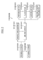
- FIG. 2 is a process flowchart of a method of manufacturing a roll for roll printing/roll imprinting according to a first exemplary embodiment of the present invention and FIG. 3 schematically illustrates the method of manufacturing a roll for roll printing/roll imprinting of FIG. 2 .
- the roll printing/roll imprinting roll manufacturing method S100 includes an exterior preparing step S110 and an exterior attaching step 120.
- the exterior preparing step S110 an exterior 120 that directly contacts an object during roll printing/roll imprinting is manufactured.
- the exterior preparing step S110 includes a substrate manufacturing step S111 and an exterior molding step S112.
- a substrate 110 for performing the function of a mold when the exterior 120 is molded is manufactured.
- a pattern of a shape corresponding to a printed pattern to be formed on the external surface of the exterior 120 is patterned on one surface of the substrate 110 so that a required printed pattern is formed in the exterior 120 described later using the substrate 110 as a mold.
- the pattern formed on the substrate 110 may be formed by one of nano lithography and imprinting, however, is not limited to the above.
- the exterior molding step S112 includes a mixture preparing step S113, a filling step S114, a hardening step S115, and a mold releasing step S116.
- ferromagnetic particles 123 are mixed with a liquid polymer resin 122 to prepare a mixture 121.
- Nano or micro particles such as nickel (Ni), cobalt (Co), and steel (Fe) may be used as the ferromagnetic particles 123 used in the present exemplary embodiment.
- polydimethylsiloxane (PDMS) or polytetrafluroethylene (PTFE) may be used as the polymer resin 122. Any polymer resin having flexibility after being hardened may be used as the polymer resin 122 without being limited to the above.
- a ferromagnetic additive may be further included in the mixture 121 so that characteristics such as strength, electric conductivtiy, and thermal conductivity are improved.
- Carbon nanotube (CNT), carbon fiber, glass fiber, or a mixture of at least two of carbon nanotube (CNT), carbon fiber, and glass fiber may be used as the ferromagnetic additive. Any additive that may help improve the characteristics of the mixture after being hardened may be used without being limited to the above.
- the liquid mixture 121 is filled in the substrate 110 that functions as a mold. At this time, the viscosity of the liquid mixture 121 is controlled so that the mixture 121 may be precisely filled in the pattern formed on the substrate 110.
- the pattern of the substrate 110 is formed before filling the mixture 121 and the surface in which the mixture 121 is filled is coated with a mold release so that the exterior 120 may be easily released from the substrate 110 later.
- the mixture 121 is liquid, however, may be powdered or semisolid in accordance with a molding conditions and the kind of material to be filled in the substrate 110. Such a modification will be described later.
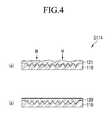
- FIGs. 4 and 5 schematically illustrate modifications of the filling step of FIG. 2 .
- the liquid mixture 121 is filled in the substrate.
- the powdered mixture 121 is filled in the substrate, is heated H, and is dissolved so that the mixture 121 may permeate into the pattern of the substrate.
- the liquid mixture 121 may be made semisolid to be pressed by the substrate 110.
- the liquid mixture 121 is hardened to form the exterior 120.
- the exterior 120 is released from the substrate 110 so that the manufacturing of the exterior 120 is finally completed.
- the molded exterior 120 is attached to the external circumferential surface of a central roll 130.
- the central roll 130 as ferromagnetic material such as a permanent magnet is a cylinder with a predetermined diameter so that the exterior 120 may be attached to the external surface of the central roll 130 by magnetic power.
- the exterior 120 When the opposite surface of the surface in which the printed pattern of the molded exterior 120 is formed contacts the external circumferential surface of the central roll 130, the exterior 120 is combined with the central roll 130 by attractive force between the ferromagnetic particles included in the exterior 120 and the central roll 130 formed of the permanent magnet.
- a roll of metal material is directly processed to manufacture a roll for roll printing/roll imprinting.
- the additional exterior 120 is processed and molded on a plane to be combined with the external circumferential surface of the central roll 130 of the magnetic material, processes may be simplified and cost may be reduced.
- a roll 100 for roll printing/roll imprinting manufactured by the present exemplary embodiment since only the exterior 120 may be detachably replaced without replacing the entire roll like in the conventional art, it is possible to conveniently and cheaply maintain and repair the roll 100 for roll printing/roll imprinting.
- FIG. 2 is a process flowchart of the roll printing/roll imprinting roll manufacturing method S100 according to the first exemplary embodiment of the present invention and a process flowchart of the roll printing/roll imprinting roll manufacturing method S200 according to the second exemplary embodiment.
- the roll printing/roll imprinting roll manufacturing method S200 includes an exterior preparing step S210 and an exterior attaching step S220.
- the exterior preparing step S210 includes a substrate manufacturing step S211 and an exterior molding step S212 like in the first exemplary embodiment. However, since the substrate manufacturing step S211 is the same as the substrate manufacturing step of the first exemplary embodiment, description thereof will be omitted.
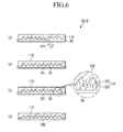
- FIG. 6 schematically illustrates the exterior molding step S212 in the roll printing/roll imprinting roll manufacturing method S200 according to the second exemplary embodiment of the present invention.
- the exterior molding step S212 includes a mixture preparing step S213, a filling step S214, a hardening step S215, and a mold releasing step S216.
- the ferromagnetic particles 123, the polymer resin 122, and the additive are mixed by the same method as the method of the first exemplary embodiment to prepare the liquid mixture 121.
- the prepared mixture 121 is filled in the substrate.
- the substrate 110 is disposed so that the formed pattern faces a gravitation direction and an additional mold 20 is prepared under the substrate to support the filled mixture 121 under the filled mixture 121 so that the filled mixture 121 does not leak.
- hardening conditions such as time, temperature, and pressure are controlled so that the ferromagnetic particles 123 included in the filled mixture 121 are moved in the gravitation direction by self-gravitation to manufacture the exterior 120.
- the density of the ferromagnetic particles 123 on the opposite side is measured to be higher than the density of the ferromagnetic particles 123 on the side where the printed pattern is formed.
- the manufactured exterior 120 is released from the substrate 110.
- the density of the ferromagnetic particles 123 is large in the position close to the central roll 130 of the exterior 120, in the exterior attaching step S220, although only a small amount of ferromagnetic particles 123 are mixed with the exterior 120, the exterior 120 and the central roll 130 may have excellent binding power.
- the printed pattern is formed in the surface of the exterior 120 where the ferromagnetic particles 123 are not dense so that a minute nano/micro printed pattern may be formed.
- FIG. 2 is a flowchart of the roll printing/roll imprinting roll manufacturing method S100 according to the first exemplary embodiment of the present invention and is a flowchart of the roll printing/roll imprinting roll manufacturing method S300 according to the third exemplary embodiment.
- the roll printing/roll imprinting roll manufacturing method S300 includes an exterior preparing step S310 and an exterior attaching step S320.
- the exterior preparing step S310 includes a substrate manufacturing step S311 and an exterior molding step S312 like in the first exemplary embodiment.
- the substrate manufacturing step S311 is the same as the substrate manufacturing step according to the first exemplary embodiment, description thereof will be omitted.
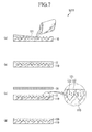
- FIG. 7 schematically illustrates the exterior molding step S312 in the roll printing/roll imprinting roll manufacturing method S300 according to the third exemplary embodiment of the present invention.
- the exterior molding step S312 includes a mixture preparing step S313, a filling step S314, a hardening step S315, and a mold releasing step S316.
- the ferromagnetic particles 123, the polymer resin 122, and the additive are mixed by the same method as the method of the first exemplary embodiment to prepare the liquid mixture 121.
- the mixture 121 is filled in the substrate 110 by the same method as the method of the first exemplary embodiment.
- the ferromagnetic particles 123 included in the filled mixture 121 are controlled to be moved to the opposite side to the side on which the printed pattern is formed.
- an additional magnetic power member 30 is disposed on the opposite side to the side on which the printed pattern of the mixture 121 is formed so that the ferromagnetic particles 123 are moved by magnetic power.
- the magnetic power member 30 may be disposed to be closely adjacent to the mixture 121 or to be separated from the mixture 121 by a predetermined distance.
- the distance by which the magnetic power member 30 is separated from the mixture 121 and magnetic power may be determined in accordance with the hardening time of the mixture 121, the travel range of the ferromagnetic particles 123, and the density distribution of the required ferromagnetic particles 123.
- the density of the ferromagnetic particles 123 on the opposite side is measured to be higher than the density of the ferromagnetic particles 123 on the side where the printed pattern is formed.
- the manufactured exterior 120 is released from the substrate 110 and the exterior 120 is formed.
- the density of the ferromagnetic particles 123 is large in the position close to the central roll 130 of the exterior 120, in the exterior attaching step S320, although only a small amount of ferromagnetic particles 123 are mixed with the exterior 120, the exterior 120 and the central roll 130 may have excellent binding power.
- the printed pattern is formed in the surface of the exterior 120 on the side where the ferromagnetic particles 123 are not dense so that so that a minute nano/micro printed pattern may be formed.
Landscapes
- Engineering & Computer Science (AREA)
- Mechanical Engineering (AREA)
- Physics & Mathematics (AREA)
- General Physics & Mathematics (AREA)
- Nonlinear Science (AREA)
- Chemical & Material Sciences (AREA)
- Crystallography & Structural Chemistry (AREA)
- Optics & Photonics (AREA)
- Shaping Of Tube Ends By Bending Or Straightening (AREA)
- Moulds For Moulding Plastics Or The Like (AREA)
- Exposure Of Semiconductors, Excluding Electron Or Ion Beam Exposure (AREA)
Abstract
Description
- The present invention relates to a method of manufacturing a roll for roll printing/roll imprinting. More particularly, the present invention relates to a method of manufacturing a roll for roll printing/roll imprinting capable of reducing manufacturing cost and time.
- As electronic and display industry related parts are down-sized and have thin plates, it is required to improve the performance of precise micro pattern manufacturing processes and, in parts manufacturing equipment, preciseness, high productivity, and cost reduction effort are essential elements.
- A producing system capable of manufacturing electronic element products and optical parts of several tens nm to several hundreds µm on a substrate formed of a flexible material using a printing process or an imprinting process is remarkably spotlighted. Particularly, in order to induce cost reduction and mass production, roll printing equipment or roll imprinting equipment such as roll-to-roll or roll-to-plate is widely used.
- In the roll printing equipment and the roll imprinting equipment, a roll corresponds to a core constituent element.
-
FIG. 1 illustrates an example of a method of manufacturing a conventional roll for roll printing/roll imprinting. Referring toFIG. 1 , in aconventional roll 10 for roll printing/roll imprinting equipment, the external surface of a cylinder formed of resin or metal material is manufactured using an additional processing machine such as alaser 11. In the method of manufacturing a roll for roll printing/roll imprinting, since the curved external surface of roll-shaped resin must be directly processed, machinability is deteriorated and there are limitations on securing a high quality pattern shape on the external circumferential surface of the roll for roll printing/roll imprinting. - In addition, the entire roll must be replaced when there is something wrong with the pattern of the external circumferential surface of the conventional roll for roll printing/roll imprinting.
- The above information disclosed in this Background section is only for enhancement of understanding of the background of the invention and therefore it may contain information that does not form the prior art that is already known in this country to a person of ordinary skill in the art.
- The present invention has been made in an effort to provide a method of manufacturing a roll for roll printing/roll imprinting having advantages of reducing manufacturing cost and time. An exemplary embodiment of the present invention provides a method of manufacturing a roll for roll printing/roll imprinting.
- Therefore, an object of the present invention is to provide a method of manufacturing a roll for roll printing/roll imprinting capable of additionally molding an exterior to be combined with a roll so that it is possible to reduce cost and time.
- In order to achieve the object, there is provided a method of manufacturing a roll for roll printing/roll imprinting, including preparing an exterior on one surface of which a printed pattern of a predetermined shape is formed and that has magnetic power and having the other surface of the exterior contact an external surface of a central roll so that the exterior is attached to the central roll having magnetic power by magnetic power.
- In addition, preparing the exterior may include manufacturing a substrate in which a mirror-shaped pattern of the pattern is formed and molding the exterior using the substrate as a mold.
- In addition, molding the exterior may include preparing a mixture including ferromagnetic particles and polymer resin, filling the mixture in the substrate, hardening the filled mixture to form the exterior, and releasing the exterior from the substrate.
- In addition, after hardening the filled mixture, a ferromagnetic additive may be further included in the mixture so that at least one of characteristics such as strength, electric conductivtiy, and thermal conductivity is improved.
- In addition, the additive may be at least one of carbon nanotube, carbon fiber, and glass fiber.
- In addition, the mixture may be disposed so that the ferromagnetic particles are moved to the direction of gravitation by self-gravitation.
- A magnetic power member may be disposed on an opposite side to a side on which the pattern of the mixture is formed so that the ferromagnetic particles are moved by magnetic power.
- In addition, the polymer resin may be flexible material.
- In addition, the polymer resin may be at least one of polydimethylsiloxane (PDMS) and polytetrafluroethylene (PTFE).
- In the method of manufacturing a roll for roll printing/roll imprinting according to the present invention, it is possible to reduce cost and time.
- In addition, ferromagnetic particles are controlled to be dense on one side of an exterior combined with a central roll so that it is possible to realize improved binding power only by a small amount of ferromagnetic particles.
- In addition, since the pattern is formed on the side of the exterior where the density of the ferromagnetic particles is low, it is possible to form a minute nano/micro pattern.
- In addition, when there is something wrong with the pattern formed on the external circumferential surface, only the exterior is replaced. Therefore, it is possible to reduce maintaining and repairing cost.
-
-
FIG. 1 illustrates an example of a method of manufacturing a conventional roll for roll printing/roll imprinting, -
FIG. 2 is a process flowchart of methods of manufacturing a roll for roll printing/roll imprinting according to first to third exemplary embodiments of the present invention, -
FIG. 3 schematically illustrates the method of manufacturing a roll for roll printing/roll imprinting ofFIG. 2 , -
FIG. 4 schematically illustrates a modification of the filling step ofFIG. 2 , -
FIG. 5 schematically illustrates another modification of the filling step ofFIG. 2 , -
FIG. 6 schematically illustrates an exterior molding step in the method of manufacturing a roll for roll printing/roll imprinting according to the second exemplary embodiment of the present invention, -
FIG. 7 schematically illustrates an exterior molding step in the method of manufacturing a roll for printing according to the third exemplary embodiment of the present invention. - Before description, in various exemplary embodiments, like reference numerals designate like constituent elements in a first exemplary embodiment and different constituent elements from the constituent elements of the first exemplary embodiment will be described in the other exemplary embodiments.
- Hereinafter, a roll printing/roll imprinting roll manufacturing method S100 according to the first exemplary embodiment of the present invention will be described with reference to the accompanying drawings.
-
FIG. 2 is a process flowchart of a method of manufacturing a roll for roll printing/roll imprinting according to a first exemplary embodiment of the present invention andFIG. 3 schematically illustrates the method of manufacturing a roll for roll printing/roll imprinting ofFIG. 2 . - Referring to
FIGs. 2 and3 , the roll printing/roll imprinting roll manufacturing method S100 according to the first exemplary embodiment of the present invention includes an exterior preparing step S110 and an exterior attachingstep 120. - In the exterior preparing step S110, an
exterior 120 that directly contacts an object during roll printing/roll imprinting is manufactured. The exterior preparing step S110 includes a substrate manufacturing step S111 and an exterior molding step S112. - Referring to
FIG. 3(a) , in the substrate manufacturing step S111, asubstrate 110 for performing the function of a mold when theexterior 120 is molded is manufactured. A pattern of a shape corresponding to a printed pattern to be formed on the external surface of theexterior 120 is patterned on one surface of thesubstrate 110 so that a required printed pattern is formed in theexterior 120 described later using thesubstrate 110 as a mold. - The pattern formed on the
substrate 110 may be formed by one of nano lithography and imprinting, however, is not limited to the above. - The exterior molding step S112 includes a mixture preparing step S113, a filling step S114, a hardening step S115, and a mold releasing step S116.
- Referring to
FIG. 3(b) , in the mixture preparing step S113,ferromagnetic particles 123 are mixed with aliquid polymer resin 122 to prepare amixture 121. - Nano or micro particles such as nickel (Ni), cobalt (Co), and steel (Fe) may be used as the
ferromagnetic particles 123 used in the present exemplary embodiment. In addition, in the present exemplary embodiment, polydimethylsiloxane (PDMS) or polytetrafluroethylene (PTFE) may be used as thepolymer resin 122. Any polymer resin having flexibility after being hardened may be used as thepolymer resin 122 without being limited to the above. - In addition, a ferromagnetic additive may be further included in the
mixture 121 so that characteristics such as strength, electric conductivtiy, and thermal conductivity are improved. - Carbon nanotube (CNT), carbon fiber, glass fiber, or a mixture of at least two of carbon nanotube (CNT), carbon fiber, and glass fiber may be used as the ferromagnetic additive. Any additive that may help improve the characteristics of the mixture after being hardened may be used without being limited to the above.
- Referring to
FIG. 3(c) , in the filling step S114, theliquid mixture 121 is filled in thesubstrate 110 that functions as a mold. At this time, the viscosity of theliquid mixture 121 is controlled so that themixture 121 may be precisely filled in the pattern formed on thesubstrate 110. - The pattern of the
substrate 110 is formed before filling themixture 121 and the surface in which themixture 121 is filled is coated with a mold release so that theexterior 120 may be easily released from thesubstrate 110 later. - On the other hand, in the present exemplary embodiment, the
mixture 121 is liquid, however, may be powdered or semisolid in accordance with a molding conditions and the kind of material to be filled in thesubstrate 110. Such a modification will be described later. -
FIGs. 4 and5 schematically illustrate modifications of the filling step ofFIG. 2 . - In the filling step S114 of the present exemplary embodiment, the
liquid mixture 121 is filled in the substrate. However, referring toFIG. 4 , in the filling step S114 of the modification, the powderedmixture 121 is filled in the substrate, is heated H, and is dissolved so that themixture 121 may permeate into the pattern of the substrate. In addition, referring toFIG. 5 , in the filling step S114 of another modification, theliquid mixture 121 may be made semisolid to be pressed by thesubstrate 110. - In the hardening step S115, the
liquid mixture 121 is hardened to form theexterior 120. - In the mold releasing step S116, the
exterior 120 is released from thesubstrate 110 so that the manufacturing of the exterior 120 is finally completed. - In an exterior attaching step S120, the molded
exterior 120 is attached to the external circumferential surface of acentral roll 130. Thecentral roll 130 as ferromagnetic material such as a permanent magnet is a cylinder with a predetermined diameter so that the exterior 120 may be attached to the external surface of thecentral roll 130 by magnetic power. - When the opposite surface of the surface in which the printed pattern of the molded
exterior 120 is formed contacts the external circumferential surface of thecentral roll 130, theexterior 120 is combined with thecentral roll 130 by attractive force between the ferromagnetic particles included in theexterior 120 and thecentral roll 130 formed of the permanent magnet. - In a conventional art, a roll of metal material is directly processed to manufacture a roll for roll printing/roll imprinting. However, according to the present exemplary embodiment, since the
additional exterior 120 is processed and molded on a plane to be combined with the external circumferential surface of thecentral roll 130 of the magnetic material, processes may be simplified and cost may be reduced. - In addition, in a
roll 100 for roll printing/roll imprinting manufactured by the present exemplary embodiment, since only the exterior 120 may be detachably replaced without replacing the entire roll like in the conventional art, it is possible to conveniently and cheaply maintain and repair theroll 100 for roll printing/roll imprinting. - Next, a method of manufacturing a roll for roll printing/roll imprinting according to a second exemplary embodiment of the present invention will be described.
-
FIG. 2 is a process flowchart of the roll printing/roll imprinting roll manufacturing method S100 according to the first exemplary embodiment of the present invention and a process flowchart of the roll printing/roll imprinting roll manufacturing method S200 according to the second exemplary embodiment. - Referring to
FIG. 2 , the roll printing/roll imprinting roll manufacturing method S200 according to the second exemplary embodiment of the present invention includes an exterior preparing step S210 and an exterior attaching step S220. - The exterior preparing step S210 includes a substrate manufacturing step S211 and an exterior molding step S212 like in the first exemplary embodiment. However, since the substrate manufacturing step S211 is the same as the substrate manufacturing step of the first exemplary embodiment, description thereof will be omitted.
-
FIG. 6 schematically illustrates the exterior molding step S212 in the roll printing/roll imprinting roll manufacturing method S200 according to the second exemplary embodiment of the present invention. - Referring to
FIG. 6 , the exterior molding step S212 includes a mixture preparing step S213, a filling step S214, a hardening step S215, and a mold releasing step S216. - In the mixture preparing step S213, the
ferromagnetic particles 123, thepolymer resin 122, and the additive are mixed by the same method as the method of the first exemplary embodiment to prepare theliquid mixture 121. - Referring to
FIG. 6(a) , in the filling step S214, theprepared mixture 121 is filled in the substrate. Unlike in the first exemplary embodiment, thesubstrate 110 is disposed so that the formed pattern faces a gravitation direction and anadditional mold 20 is prepared under the substrate to support the filledmixture 121 under the filledmixture 121 so that the filledmixture 121 does not leak. - Referring to
FIGs. 6(b) and 6(c) , in the hardening step S215, hardening conditions such as time, temperature, and pressure are controlled so that theferromagnetic particles 123 included in the filledmixture 121 are moved in the gravitation direction by self-gravitation to manufacture theexterior 120. - Therefore, referring to
FIG. 6(d) , in the exterior 120 formed in the hardening step S215 of the present exemplary embodiment, the density of theferromagnetic particles 123 on the opposite side is measured to be higher than the density of theferromagnetic particles 123 on the side where the printed pattern is formed. - In the mold releasing step S216, the manufactured
exterior 120 is released from thesubstrate 110. - Therefore, according to the present exemplary embodiment, since the density of the
ferromagnetic particles 123 is large in the position close to thecentral roll 130 of the exterior 120, in the exterior attaching step S220, although only a small amount offerromagnetic particles 123 are mixed with the exterior 120, theexterior 120 and thecentral roll 130 may have excellent binding power. In addition, the printed pattern is formed in the surface of the exterior 120 where theferromagnetic particles 123 are not dense so that a minute nano/micro printed pattern may be formed. - Next, a method of manufacturing a roll for roll printing/roll imprinting according to a third exemplary embodiment of the present invention will be described.
-
FIG. 2 is a flowchart of the roll printing/roll imprinting roll manufacturing method S100 according to the first exemplary embodiment of the present invention and is a flowchart of the roll printing/roll imprinting roll manufacturing method S300 according to the third exemplary embodiment. - Referring to
FIG. 2 , the roll printing/roll imprinting roll manufacturing method S300 according to the third exemplary embodiment of the present invention includes an exterior preparing step S310 and an exterior attaching step S320. - The exterior preparing step S310 includes a substrate manufacturing step S311 and an exterior molding step S312 like in the first exemplary embodiment. However, since the substrate manufacturing step S311 is the same as the substrate manufacturing step according to the first exemplary embodiment, description thereof will be omitted.
-
FIG. 7 schematically illustrates the exterior molding step S312 in the roll printing/roll imprinting roll manufacturing method S300 according to the third exemplary embodiment of the present invention. - Referring to
FIG. 7 , the exterior molding step S312 includes a mixture preparing step S313, a filling step S314, a hardening step S315, and a mold releasing step S316. - In the mixture preparing step S313, the
ferromagnetic particles 123, thepolymer resin 122, and the additive are mixed by the same method as the method of the first exemplary embodiment to prepare theliquid mixture 121. - Referring to
FIG. 7(a) , in the filling step S314, themixture 121 is filled in thesubstrate 110 by the same method as the method of the first exemplary embodiment. - Referring to
FIGs. 7(b) to 7(d) , in the hardening step S315, theferromagnetic particles 123 included in the filledmixture 121 are controlled to be moved to the opposite side to the side on which the printed pattern is formed. Unlike in the method of using self-gravitation of the second exemplary embodiment, in the present exemplary embodiment, an additionalmagnetic power member 30 is disposed on the opposite side to the side on which the printed pattern of themixture 121 is formed so that theferromagnetic particles 123 are moved by magnetic power. - At this time, the
magnetic power member 30 may be disposed to be closely adjacent to themixture 121 or to be separated from themixture 121 by a predetermined distance. The distance by which themagnetic power member 30 is separated from themixture 121 and magnetic power may be determined in accordance with the hardening time of themixture 121, the travel range of theferromagnetic particles 123, and the density distribution of the requiredferromagnetic particles 123. - Therefore, referring to
FIG. 7 , in the exterior 120 formed in the hardening step S315 of the present exemplary embodiment, the density of theferromagnetic particles 123 on the opposite side is measured to be higher than the density of theferromagnetic particles 123 on the side where the printed pattern is formed. - In the mold releasing step S316, the manufactured
exterior 120 is released from thesubstrate 110 and the exterior 120 is formed. - Therefore, according to the present exemplary embodiment, since the density of the
ferromagnetic particles 123 is large in the position close to thecentral roll 130 of the exterior 120, in the exterior attaching step S320, although only a small amount offerromagnetic particles 123 are mixed with the exterior 120, theexterior 120 and thecentral roll 130 may have excellent binding power. In addition, the printed pattern is formed in the surface of the exterior 120 on the side where theferromagnetic particles 123 are not dense so that so that a minute nano/micro printed pattern may be formed. - The scope of the present invention is not limited to the above-described embodiments but may be realized by various exemplary embodiments within the range of the appended claims.
- While this invention has been described in connection with what is presently considered to be practical exemplary embodiments, it is to be understood that the invention is not limited to the disclosed embodiments, but, on the contrary, is intended to cover various modifications and equivalent arrangements included within the spirit and scope of the appended claims.
Claims (10)
- A method of manufacturing a roll for roll printing/roll imprinting, comprising:preparing an exterior on one surface of which a printed pattern of a predetermined shape is formed and that has magnetic power; andhaving the other surface of the exterior contact an external surface of a central roll so that the exterior is attached to the central roll having magnetic power by magnetic power.
- The method of claim 1, wherein preparing the exterior comprises:manufacturing a substrate in which a mirror-shaped pattern of the pattern is formed; andmolding the exterior using the substrate as a mold.
- The method of claim 2, wherein molding the exterior comprises:preparing a mixture including ferromagnetic particles and polymer resin;filling the mixture in the substrate;hardening the filled mixture to form the exterior; andreleasing the exterior from the substrate.
- The method of claim 3, wherein, in hardening the filled mixture, the mixture is hardened so that the ferromagnetic particles are moved to an opposite side to a side on which the pattern is formed.
- The method of claim 3, wherein, after hardening the filled mixture, a ferromagnetic additive is further included in the mixture so that at least one of characteristics such as strength, electric conductivtiy, and thermal conductivity is improved.
- The method of claim 5, wherein the additive is at least one of carbon nanotube, carbon fiber, and glass fiber.
- The method of claim 4, wherein the mixture is disposed so that the ferromagnetic particles are moved to the direction of gravitation by self-gravitation.
- The method of claim 4, wherein a magnetic power member is disposed on an opposite side to a side on which the pattern of the mixture is formed so that the ferromagnetic particles are moved by magnetic power.
- The method of any one of claim 1 to claim 8, wherein the polymer resin is flexible material.
- The method of claim 9, wherein the polymer resin is at least one of polydimethylsiloxane (PDMS) and polytetrafluroethylene (PTFE).
Applications Claiming Priority (2)
| Application Number | Priority Date | Filing Date | Title |
|---|---|---|---|
| KR1020100125884A KR101037903B1 (en) | 2010-12-09 | 2010-12-09 | Roll manufacturing method for roll printing / roll imprinting |
| PCT/KR2011/009522 WO2012078009A2 (en) | 2010-12-09 | 2011-12-09 | Method for manufacturing a roll for roll printing/roll imprinting |
Publications (3)
| Publication Number | Publication Date |
|---|---|
| EP2650904A2 true EP2650904A2 (en) | 2013-10-16 |
| EP2650904A4 EP2650904A4 (en) | 2015-02-18 |
| EP2650904B1 EP2650904B1 (en) | 2017-02-01 |
Family
ID=44366785
Family Applications (1)
| Application Number | Title | Priority Date | Filing Date |
|---|---|---|---|
| EP11847066.5A Not-in-force EP2650904B1 (en) | 2010-12-09 | 2011-12-09 | Method for manufacturing a roll for roll printing/roll imprinting |
Country Status (5)
| Country | Link |
|---|---|
| US (1) | US9211575B2 (en) |
| EP (1) | EP2650904B1 (en) |
| JP (1) | JP5774689B2 (en) |
| KR (1) | KR101037903B1 (en) |
| WO (1) | WO2012078009A2 (en) |
Families Citing this family (4)
| Publication number | Priority date | Publication date | Assignee | Title |
|---|---|---|---|---|
| FR2959162B3 (en) * | 2010-04-26 | 2012-03-23 | Innopsys | SOFT LITHOGRAPHY DEVICE AND METHOD |
| TW201325884A (en) * | 2011-12-29 | 2013-07-01 | Hon Hai Prec Ind Co Ltd | Pressing roller for producing optical film and manufacturing method of the press roller |
| DE102013013602A1 (en) * | 2013-08-19 | 2015-02-19 | Trützschler GmbH + Co KG Textilmaschinenfabrik | Device on a card or carding machine for cotton, man-made fibers u. Like. With a rotatable stripper |
| KR101692065B1 (en) * | 2016-06-07 | 2017-01-03 | 한국기계연구원 | A method and apparatus for forming a fine pattern roll |
Family Cites Families (29)
| Publication number | Priority date | Publication date | Assignee | Title |
|---|---|---|---|---|
| US3217641A (en) | 1963-04-24 | 1965-11-16 | Goffredo Daniel Louis | Plastic printing plate method and product |
| US3670646A (en) * | 1970-10-09 | 1972-06-20 | Grace W R & Co | Magnetically securable printing plate |
| US4078031A (en) * | 1974-03-18 | 1978-03-07 | Bishop Homer L | Method of making a magnetic flexible printing plate |
| JPS5315825Y2 (en) * | 1974-07-30 | 1978-04-25 | ||
| JPS5120076A (en) | 1974-08-13 | 1976-02-17 | Nittetsu Kakoki Kk | TOYOJUTEN BUTSU |
| US4028786A (en) * | 1974-10-08 | 1977-06-14 | Canathane Roller Corporation Limited | Printing and like rollers |
| JP2827599B2 (en) | 1991-07-25 | 1998-11-25 | 富士電機株式会社 | Variable throttle valve |
| JPH0526370U (en) * | 1991-09-12 | 1993-04-06 | 日立電線株式会社 | Surface printing device for coated electric wire |
| DE69330341T2 (en) * | 1992-09-24 | 2001-09-20 | Toto Ltd., Kitakyushu | MATERIAL WITH DEPENDENT GRADIENT AND THEIR PRODUCTION |
| GB9400436D0 (en) | 1994-01-12 | 1994-03-09 | Diversey Corp | Lubricant compositions |
| IT1280163B1 (en) * | 1995-04-27 | 1998-01-05 | G M P Poliuretani Srl | PROCEDURE FOR THE CREATION OF POLYMER PRODUCTS WITH DIFFERENTIATED CONDUCTIVITY AND RELATED DEVICE |
| WO1997015623A1 (en) * | 1995-10-27 | 1997-05-01 | Daikin Industries, Ltd. | Resin composition, molding produced using the same, and process for producing the same |
| DE20019097U1 (en) | 2000-11-10 | 2001-02-22 | Wegter, Bernd, 48527 Nordhorn | Punching device |
| JP2006018061A (en) | 2004-07-02 | 2006-01-19 | Bridgestone Corp | Magnet roller |
| KR20060008540A (en) * | 2004-07-21 | 2006-01-27 | 엘지전자 주식회사 | Fine filler to form the surface of the resin injection molding and injection apparatus and method using the same |
| JP4792323B2 (en) | 2006-04-04 | 2011-10-12 | 明昌機工株式会社 | Nanoimprint apparatus and nanoimprint method |
| TWI322927B (en) * | 2006-05-24 | 2010-04-01 | Ind Tech Res Inst | Roller module for microstructure thin film imprint |
| JP4835277B2 (en) | 2006-06-15 | 2011-12-14 | 大日本印刷株式会社 | Pattern forming body manufacturing method and imprint transfer apparatus |
| KR101296638B1 (en) * | 2006-12-07 | 2013-08-14 | 엘지디스플레이 주식회사 | Apparatus And Method of Fabricating Thin Film Pattern |
| KR100784826B1 (en) | 2006-12-29 | 2007-12-14 | 한국기계연구원 | Nanoimprinting Lithography Apparatus Using Rollstamps |
| KR100851068B1 (en) | 2007-02-01 | 2008-08-12 | 삼성전기주식회사 | Stamper and PCB manufacturing method using thereof |
| JP5288716B2 (en) | 2007-03-16 | 2013-09-11 | 公益財団法人神奈川科学技術アカデミー | Method for producing imprint roll mold |
| JP2008290330A (en) | 2007-05-24 | 2008-12-04 | Oji Paper Co Ltd | Nanoimprint sheet manufacturing apparatus and manufacturing method |
| JP4875203B2 (en) | 2008-02-27 | 2012-02-15 | シャープ株式会社 | Roller type nanoimprint apparatus and method for producing nanoimprint sheet |
| KR100953953B1 (en) | 2008-06-03 | 2010-04-21 | 하나마이크로(주) | Roll Mold for Imprint Device |
| KR20100036484A (en) | 2008-09-30 | 2010-04-08 | 한국생산기술연구원 | Stamp and stamping method using thereof |
| IT1391357B1 (en) | 2008-10-07 | 2011-12-13 | P R Nastri Trasportatori S N C Di Rubino Vincenzo & Rubino Attilio | COMPOSITE MATERIAL THAT CAN BE DETECTED BY METAL DETECTOR, ITEM IN SUCH COMPOSITE MATERIAL AND METHOD OF OBTAINING THESE ARTICLE |
| JP5449789B2 (en) | 2009-01-29 | 2014-03-19 | 藤森工業株式会社 | Method for producing imprint transfer film roll body, and imprint transfer film roll body |
| KR20100011462U (en) | 2009-05-15 | 2010-11-24 | 주식회사 디엠에스 | Roll printing apparatus |
-
2010
- 2010-12-09 KR KR1020100125884A patent/KR101037903B1/en active Active
-
2011
- 2011-12-09 WO PCT/KR2011/009522 patent/WO2012078009A2/en not_active Ceased
- 2011-12-09 US US13/703,396 patent/US9211575B2/en active Active
- 2011-12-09 EP EP11847066.5A patent/EP2650904B1/en not_active Not-in-force
- 2011-12-09 JP JP2013514124A patent/JP5774689B2/en not_active Expired - Fee Related
Also Published As
| Publication number | Publication date |
|---|---|
| WO2012078009A3 (en) | 2012-09-07 |
| US9211575B2 (en) | 2015-12-15 |
| KR101037903B1 (en) | 2011-05-30 |
| JP2013534476A (en) | 2013-09-05 |
| JP5774689B2 (en) | 2015-09-09 |
| EP2650904A4 (en) | 2015-02-18 |
| EP2650904B1 (en) | 2017-02-01 |
| WO2012078009A2 (en) | 2012-06-14 |
| US20130263453A1 (en) | 2013-10-10 |
Similar Documents
| Publication | Publication Date | Title |
|---|---|---|
| John et al. | Large-area, continuous roll-to-roll nanoimprinting with PFPE composite molds | |
| EP2483744B1 (en) | Injection molding tools with micro/nano-meter pattern | |
| EP2650904B1 (en) | Method for manufacturing a roll for roll printing/roll imprinting | |
| EP2888629B1 (en) | Method for microcontact printing | |
| CN113238456B (en) | An imprinting method using a flexible mold core with varying thickness | |
| US20110259223A1 (en) | Soft lithography device and process | |
| JP2011251526A5 (en) | ||
| CN102758226B (en) | Accurate electroplating machining method for long-grating roller stamping mould for machine tool | |
| JP2010260279A (en) | Mold stamper manufacturing method, mold stamper and molded product manufacturing method | |
| Lopera et al. | Plasma‐Based Surface Modification of Polydimethylsiloxane for PDMS‐PDMS Molding | |
| KR20200062141A (en) | A roll stamp for imprint apparatus and a manufacturing method of the same | |
| Müller et al. | Hybridizing 3D printing and electroplating for the controlled forming of metal structures within fused deposition modelled contours | |
| KR20100089626A (en) | A production method and a manufacturing appartus for a stamper having a curved surface | |
| JP2023122562A (en) | Shape imitation mold, shape imitation, and manufacturing method thereof | |
| KR101097285B1 (en) | Variable mold manufacturing method using magnetic and pattern formation method using the same | |
| Choonee et al. | Multilevel self-aligned microcontact printing system | |
| Wen et al. | Innovative rapid replication of microlens arrays using electromagnetic force-assisted UV imprinting | |
| KR100927481B1 (en) | Method of manufacturing micro-nano metal structures | |
| JP5624396B2 (en) | Anisotropic conductive sheet and method for producing anisotropic conductive sheet | |
| KR101065707B1 (en) | A production method of a stamper for an injection mold | |
| Hsu et al. | A double-sided PDMS mold for double-sided embossing by rollers | |
| KR100987456B1 (en) | How to make a surface stamper | |
| CN117020596B (en) | A method for producing a mushroom-shaped array of through-hole molds and its application | |
| Pradyumna et al. | Fabrication of PDMS soft stamps for nanoimprint lithography (NIL) | |
| Park et al. | Fabrication of a roller type PDMS stamp using SU-8 concave molds and its application for roll contact printing |
Legal Events
| Date | Code | Title | Description |
|---|---|---|---|
| PUAI | Public reference made under article 153(3) epc to a published international application that has entered the european phase |
Free format text: ORIGINAL CODE: 0009012 |
|
| 17P | Request for examination filed |
Effective date: 20121207 |
|
| AK | Designated contracting states |
Kind code of ref document: A2 Designated state(s): AL AT BE BG CH CY CZ DE DK EE ES FI FR GB GR HR HU IE IS IT LI LT LU LV MC MK MT NL NO PL PT RO RS SE SI SK SM TR |
|
| DAX | Request for extension of the european patent (deleted) | ||
| A4 | Supplementary search report drawn up and despatched |
Effective date: 20150121 |
|
| RIC1 | Information provided on ipc code assigned before grant |
Ipc: G02F 1/13 20060101ALI20150115BHEP Ipc: H01L 21/027 20060101AFI20150115BHEP Ipc: B29C 33/42 20060101ALI20150115BHEP Ipc: B29C 41/36 20060101ALI20150115BHEP |
|
| 17Q | First examination report despatched |
Effective date: 20151130 |
|
| GRAP | Despatch of communication of intention to grant a patent |
Free format text: ORIGINAL CODE: EPIDOSNIGR1 |
|
| INTG | Intention to grant announced |
Effective date: 20160922 |
|
| GRAS | Grant fee paid |
Free format text: ORIGINAL CODE: EPIDOSNIGR3 |
|
| GRAA | (expected) grant |
Free format text: ORIGINAL CODE: 0009210 |
|
| AK | Designated contracting states |
Kind code of ref document: B1 Designated state(s): AL AT BE BG CH CY CZ DE DK EE ES FI FR GB GR HR HU IE IS IT LI LT LU LV MC MK MT NL NO PL PT RO RS SE SI SK SM TR |
|
| REG | Reference to a national code |
Ref country code: GB Ref legal event code: FG4D |
|
| REG | Reference to a national code |
Ref country code: CH Ref legal event code: EP Ref country code: AT Ref legal event code: REF Ref document number: 866193 Country of ref document: AT Kind code of ref document: T Effective date: 20170215 |
|
| REG | Reference to a national code |
Ref country code: IE Ref legal event code: FG4D |
|
| REG | Reference to a national code |
Ref country code: DE Ref legal event code: R096 Ref document number: 602011034829 Country of ref document: DE |
|
| REG | Reference to a national code |
Ref country code: NL Ref legal event code: MP Effective date: 20170201 |
|
| REG | Reference to a national code |
Ref country code: LT Ref legal event code: MG4D |
|
| REG | Reference to a national code |
Ref country code: AT Ref legal event code: MK05 Ref document number: 866193 Country of ref document: AT Kind code of ref document: T Effective date: 20170201 |
|
| PG25 | Lapsed in a contracting state [announced via postgrant information from national office to epo] |
Ref country code: IS Free format text: LAPSE BECAUSE OF FAILURE TO SUBMIT A TRANSLATION OF THE DESCRIPTION OR TO PAY THE FEE WITHIN THE PRESCRIBED TIME-LIMIT Effective date: 20170601 Ref country code: GR Free format text: LAPSE BECAUSE OF FAILURE TO SUBMIT A TRANSLATION OF THE DESCRIPTION OR TO PAY THE FEE WITHIN THE PRESCRIBED TIME-LIMIT Effective date: 20170502 Ref country code: LT Free format text: LAPSE BECAUSE OF FAILURE TO SUBMIT A TRANSLATION OF THE DESCRIPTION OR TO PAY THE FEE WITHIN THE PRESCRIBED TIME-LIMIT Effective date: 20170201 Ref country code: NO Free format text: LAPSE BECAUSE OF FAILURE TO SUBMIT A TRANSLATION OF THE DESCRIPTION OR TO PAY THE FEE WITHIN THE PRESCRIBED TIME-LIMIT Effective date: 20170501 Ref country code: HR Free format text: LAPSE BECAUSE OF FAILURE TO SUBMIT A TRANSLATION OF THE DESCRIPTION OR TO PAY THE FEE WITHIN THE PRESCRIBED TIME-LIMIT Effective date: 20170201 Ref country code: FI Free format text: LAPSE BECAUSE OF FAILURE TO SUBMIT A TRANSLATION OF THE DESCRIPTION OR TO PAY THE FEE WITHIN THE PRESCRIBED TIME-LIMIT Effective date: 20170201 |
|
| PG25 | Lapsed in a contracting state [announced via postgrant information from national office to epo] |
Ref country code: LV Free format text: LAPSE BECAUSE OF FAILURE TO SUBMIT A TRANSLATION OF THE DESCRIPTION OR TO PAY THE FEE WITHIN THE PRESCRIBED TIME-LIMIT Effective date: 20170201 Ref country code: NL Free format text: LAPSE BECAUSE OF FAILURE TO SUBMIT A TRANSLATION OF THE DESCRIPTION OR TO PAY THE FEE WITHIN THE PRESCRIBED TIME-LIMIT Effective date: 20170201 Ref country code: ES Free format text: LAPSE BECAUSE OF FAILURE TO SUBMIT A TRANSLATION OF THE DESCRIPTION OR TO PAY THE FEE WITHIN THE PRESCRIBED TIME-LIMIT Effective date: 20170201 Ref country code: AT Free format text: LAPSE BECAUSE OF FAILURE TO SUBMIT A TRANSLATION OF THE DESCRIPTION OR TO PAY THE FEE WITHIN THE PRESCRIBED TIME-LIMIT Effective date: 20170201 Ref country code: SE Free format text: LAPSE BECAUSE OF FAILURE TO SUBMIT A TRANSLATION OF THE DESCRIPTION OR TO PAY THE FEE WITHIN THE PRESCRIBED TIME-LIMIT Effective date: 20170201 Ref country code: PT Free format text: LAPSE BECAUSE OF FAILURE TO SUBMIT A TRANSLATION OF THE DESCRIPTION OR TO PAY THE FEE WITHIN THE PRESCRIBED TIME-LIMIT Effective date: 20170601 Ref country code: PL Free format text: LAPSE BECAUSE OF FAILURE TO SUBMIT A TRANSLATION OF THE DESCRIPTION OR TO PAY THE FEE WITHIN THE PRESCRIBED TIME-LIMIT Effective date: 20170201 Ref country code: BG Free format text: LAPSE BECAUSE OF FAILURE TO SUBMIT A TRANSLATION OF THE DESCRIPTION OR TO PAY THE FEE WITHIN THE PRESCRIBED TIME-LIMIT Effective date: 20170501 Ref country code: RS Free format text: LAPSE BECAUSE OF FAILURE TO SUBMIT A TRANSLATION OF THE DESCRIPTION OR TO PAY THE FEE WITHIN THE PRESCRIBED TIME-LIMIT Effective date: 20170201 |
|
| PG25 | Lapsed in a contracting state [announced via postgrant information from national office to epo] |
Ref country code: CZ Free format text: LAPSE BECAUSE OF FAILURE TO SUBMIT A TRANSLATION OF THE DESCRIPTION OR TO PAY THE FEE WITHIN THE PRESCRIBED TIME-LIMIT Effective date: 20170201 Ref country code: SK Free format text: LAPSE BECAUSE OF FAILURE TO SUBMIT A TRANSLATION OF THE DESCRIPTION OR TO PAY THE FEE WITHIN THE PRESCRIBED TIME-LIMIT Effective date: 20170201 Ref country code: IT Free format text: LAPSE BECAUSE OF FAILURE TO SUBMIT A TRANSLATION OF THE DESCRIPTION OR TO PAY THE FEE WITHIN THE PRESCRIBED TIME-LIMIT Effective date: 20170201 Ref country code: EE Free format text: LAPSE BECAUSE OF FAILURE TO SUBMIT A TRANSLATION OF THE DESCRIPTION OR TO PAY THE FEE WITHIN THE PRESCRIBED TIME-LIMIT Effective date: 20170201 Ref country code: RO Free format text: LAPSE BECAUSE OF FAILURE TO SUBMIT A TRANSLATION OF THE DESCRIPTION OR TO PAY THE FEE WITHIN THE PRESCRIBED TIME-LIMIT Effective date: 20170201 |
|
| REG | Reference to a national code |
Ref country code: DE Ref legal event code: R097 Ref document number: 602011034829 Country of ref document: DE |
|
| REG | Reference to a national code |
Ref country code: FR Ref legal event code: PLFP Year of fee payment: 7 |
|
| PG25 | Lapsed in a contracting state [announced via postgrant information from national office to epo] |
Ref country code: SM Free format text: LAPSE BECAUSE OF FAILURE TO SUBMIT A TRANSLATION OF THE DESCRIPTION OR TO PAY THE FEE WITHIN THE PRESCRIBED TIME-LIMIT Effective date: 20170201 Ref country code: DK Free format text: LAPSE BECAUSE OF FAILURE TO SUBMIT A TRANSLATION OF THE DESCRIPTION OR TO PAY THE FEE WITHIN THE PRESCRIBED TIME-LIMIT Effective date: 20170201 |
|
| PLBE | No opposition filed within time limit |
Free format text: ORIGINAL CODE: 0009261 |
|
| STAA | Information on the status of an ep patent application or granted ep patent |
Free format text: STATUS: NO OPPOSITION FILED WITHIN TIME LIMIT |
|
| 26N | No opposition filed |
Effective date: 20171103 |
|
| PG25 | Lapsed in a contracting state [announced via postgrant information from national office to epo] |
Ref country code: SI Free format text: LAPSE BECAUSE OF FAILURE TO SUBMIT A TRANSLATION OF THE DESCRIPTION OR TO PAY THE FEE WITHIN THE PRESCRIBED TIME-LIMIT Effective date: 20170201 |
|
| REG | Reference to a national code |
Ref country code: CH Ref legal event code: PL |
|
| REG | Reference to a national code |
Ref country code: IE Ref legal event code: MM4A |
|
| PG25 | Lapsed in a contracting state [announced via postgrant information from national office to epo] |
Ref country code: MT Free format text: LAPSE BECAUSE OF NON-PAYMENT OF DUE FEES Effective date: 20171209 Ref country code: LU Free format text: LAPSE BECAUSE OF NON-PAYMENT OF DUE FEES Effective date: 20171209 |
|
| REG | Reference to a national code |
Ref country code: BE Ref legal event code: MM Effective date: 20171231 |
|
| PG25 | Lapsed in a contracting state [announced via postgrant information from national office to epo] |
Ref country code: IE Free format text: LAPSE BECAUSE OF NON-PAYMENT OF DUE FEES Effective date: 20171209 |
|
| PG25 | Lapsed in a contracting state [announced via postgrant information from national office to epo] |
Ref country code: CH Free format text: LAPSE BECAUSE OF NON-PAYMENT OF DUE FEES Effective date: 20171231 Ref country code: LI Free format text: LAPSE BECAUSE OF NON-PAYMENT OF DUE FEES Effective date: 20171231 Ref country code: BE Free format text: LAPSE BECAUSE OF NON-PAYMENT OF DUE FEES Effective date: 20171231 |
|
| PG25 | Lapsed in a contracting state [announced via postgrant information from national office to epo] |
Ref country code: MC Free format text: LAPSE BECAUSE OF FAILURE TO SUBMIT A TRANSLATION OF THE DESCRIPTION OR TO PAY THE FEE WITHIN THE PRESCRIBED TIME-LIMIT Effective date: 20170201 Ref country code: HU Free format text: LAPSE BECAUSE OF FAILURE TO SUBMIT A TRANSLATION OF THE DESCRIPTION OR TO PAY THE FEE WITHIN THE PRESCRIBED TIME-LIMIT; INVALID AB INITIO Effective date: 20111209 |
|
| PG25 | Lapsed in a contracting state [announced via postgrant information from national office to epo] |
Ref country code: CY Free format text: LAPSE BECAUSE OF NON-PAYMENT OF DUE FEES Effective date: 20170201 |
|
| PG25 | Lapsed in a contracting state [announced via postgrant information from national office to epo] |
Ref country code: MK Free format text: LAPSE BECAUSE OF FAILURE TO SUBMIT A TRANSLATION OF THE DESCRIPTION OR TO PAY THE FEE WITHIN THE PRESCRIBED TIME-LIMIT Effective date: 20170201 |
|
| PG25 | Lapsed in a contracting state [announced via postgrant information from national office to epo] |
Ref country code: TR Free format text: LAPSE BECAUSE OF FAILURE TO SUBMIT A TRANSLATION OF THE DESCRIPTION OR TO PAY THE FEE WITHIN THE PRESCRIBED TIME-LIMIT Effective date: 20170201 |
|
| PG25 | Lapsed in a contracting state [announced via postgrant information from national office to epo] |
Ref country code: AL Free format text: LAPSE BECAUSE OF FAILURE TO SUBMIT A TRANSLATION OF THE DESCRIPTION OR TO PAY THE FEE WITHIN THE PRESCRIBED TIME-LIMIT Effective date: 20170201 |
|
| PGFP | Annual fee paid to national office [announced via postgrant information from national office to epo] |
Ref country code: FR Payment date: 20201112 Year of fee payment: 10 Ref country code: GB Payment date: 20201203 Year of fee payment: 10 Ref country code: DE Payment date: 20201124 Year of fee payment: 10 |
|
| REG | Reference to a national code |
Ref country code: DE Ref legal event code: R119 Ref document number: 602011034829 Country of ref document: DE |
|
| GBPC | Gb: european patent ceased through non-payment of renewal fee |
Effective date: 20211209 |
|
| PG25 | Lapsed in a contracting state [announced via postgrant information from national office to epo] |
Ref country code: GB Free format text: LAPSE BECAUSE OF NON-PAYMENT OF DUE FEES Effective date: 20211209 Ref country code: DE Free format text: LAPSE BECAUSE OF NON-PAYMENT OF DUE FEES Effective date: 20220701 |
|
| PG25 | Lapsed in a contracting state [announced via postgrant information from national office to epo] |
Ref country code: FR Free format text: LAPSE BECAUSE OF NON-PAYMENT OF DUE FEES Effective date: 20211231 |