EP2650864A2 - Leuchte mit Leuchtdioden - Google Patents
Leuchte mit Leuchtdioden Download PDFInfo
- Publication number
- EP2650864A2 EP2650864A2 EP13001928.4A EP13001928A EP2650864A2 EP 2650864 A2 EP2650864 A2 EP 2650864A2 EP 13001928 A EP13001928 A EP 13001928A EP 2650864 A2 EP2650864 A2 EP 2650864A2
- Authority
- EP
- European Patent Office
- Prior art keywords
- housing
- luminaire according
- washer
- boards
- screw
- Prior art date
- Legal status (The legal status is an assumption and is not a legal conclusion. Google has not performed a legal analysis and makes no representation as to the accuracy of the status listed.)
- Granted
Links
Images


Classifications
-
- G—PHYSICS
- G09—EDUCATION; CRYPTOGRAPHY; DISPLAY; ADVERTISING; SEALS
- G09F—DISPLAYING; ADVERTISING; SIGNS; LABELS OR NAME-PLATES; SEALS
- G09F13/00—Illuminated signs; Luminous advertising
- G09F13/04—Signs, boards or panels, illuminated from behind the insignia
-
- G—PHYSICS
- G09—EDUCATION; CRYPTOGRAPHY; DISPLAY; ADVERTISING; SEALS
- G09F—DISPLAYING; ADVERTISING; SIGNS; LABELS OR NAME-PLATES; SEALS
- G09F13/00—Illuminated signs; Luminous advertising
- G09F13/04—Signs, boards or panels, illuminated from behind the insignia
- G09F13/0418—Constructional details
- G09F13/0436—Signs, boards or panels attached to ceilings
-
- G—PHYSICS
- G09—EDUCATION; CRYPTOGRAPHY; DISPLAY; ADVERTISING; SEALS
- G09F—DISPLAYING; ADVERTISING; SIGNS; LABELS OR NAME-PLATES; SEALS
- G09F13/00—Illuminated signs; Luminous advertising
- G09F13/04—Signs, boards or panels, illuminated from behind the insignia
- G09F13/0418—Constructional details
- G09F13/0445—Frames
-
- G—PHYSICS
- G09—EDUCATION; CRYPTOGRAPHY; DISPLAY; ADVERTISING; SEALS
- G09F—DISPLAYING; ADVERTISING; SIGNS; LABELS OR NAME-PLATES; SEALS
- G09F13/00—Illuminated signs; Luminous advertising
- G09F13/20—Illuminated signs; Luminous advertising with luminescent surfaces or parts
- G09F13/22—Illuminated signs; Luminous advertising with luminescent surfaces or parts electroluminescent
-
- G—PHYSICS
- G09—EDUCATION; CRYPTOGRAPHY; DISPLAY; ADVERTISING; SEALS
- G09F—DISPLAYING; ADVERTISING; SIGNS; LABELS OR NAME-PLATES; SEALS
- G09F13/00—Illuminated signs; Luminous advertising
- G09F13/04—Signs, boards or panels, illuminated from behind the insignia
- G09F13/0418—Constructional details
- G09F2013/05—Constructional details indicating exit way or orientation
-
- G—PHYSICS
- G09—EDUCATION; CRYPTOGRAPHY; DISPLAY; ADVERTISING; SEALS
- G09F—DISPLAYING; ADVERTISING; SIGNS; LABELS OR NAME-PLATES; SEALS
- G09F13/00—Illuminated signs; Luminous advertising
- G09F13/20—Illuminated signs; Luminous advertising with luminescent surfaces or parts
- G09F13/22—Illuminated signs; Luminous advertising with luminescent surfaces or parts electroluminescent
- G09F2013/222—Illuminated signs; Luminous advertising with luminescent surfaces or parts electroluminescent with LEDs
Definitions
- the invention relates to a lamp according to the preamble of claim 1.
- the lamp consists of a housing for receiving a control gear and a lighting means, the lighting means is formed of light emitting diodes (LED), which are arranged on a circuit board and which is fixed in the housing by means of screws , For this purpose, it is necessary to provide a receiving area in the board, so for example a perforation, for the screw.
- LED light emitting diodes
- LED boards are to be attached to a mounting plate or luminaire housing using a special double-sided adhesive tape. Due to the thermal stress and because of low contact pressure in the assembly, it can happen that the adhesive dissolves and the LED board hangs down, Another disadvantage of the method just described is the inaccuracy with which the LED boards are placed.
- the present invention is based on the object of further developing a luminaire according to the preamble of claim 1 such that luminous means in the form of LED circuit boards can be mounted simply and reliably as well as accurately.
- a threaded passage is provided on both end sides of the board.
- each of the thread passages can open a screw with a washer so as to allow the board to pass through the two washers on both faces.
- the circuit boards may be placed next to one another such that a screw with a washer fixes at least two circuit boards in the housing.
- the housing accommodates four circuit boards which are arranged offset by 90 degrees.
- the boards arranged in this way enclose a rectangle or square.
- each screw receives a second washer whose outer diameter is smaller than the outer diameter of the first washer, wherein the second washer forms a longitudinal stop for the board.
- the washers are designed as plastic discs.
- the second washer preferably has an inner diameter which is greater than the outer diameter of the threaded passage.
- the second washer is made in a further embodiment by about 0.2 mm higher than the board, so that too much pressure on the board can be exercised, which could lead to tilting or tilting of the board or shim.
- the lamp according to the invention is cuboidal or cuboidal, wherein the housing top can be made of a gsieftigten aluminum sheet carrier element. All other housing walls are preferably made of translucent material, preferably plastic. The top of the housing carries the boards. Such a luminaire can be designed as so-called emergency lighting. In this case, the housing walls are covered with pictograms.
- FIG. 1 a luminaire according to the invention is shown.
- This consists of a housing top, which is designed as made of aluminum sheet carrier element (1). All other housing walls (9) are made of translucent material, preferably plastic, for example made of 3 mm thick PMMA. If the luminaire is designed as a rescue sign lamp, the inside of the side walls can be printed with escape signs.
- the side walls are bolted to the support element (1) and the bottom of the housing is glued to the side walls.
- a reflecting layer (12) for example an aluminum reflector or a reflecting foil, can be placed on the underside of the housing in order to better distribute the light emitted by the light-emitting diodes (LED) mounted on printed circuit boards (LED) to the side walls.
- LED light-emitting diodes
- the carrier element (1) is shown this takes an operating device (2), electrical terminals (5, 6) and an accumulator (4), which provides in emergency operation for the power supply of the lamp on the functionality and the charging status of the accumulator (4) must be displayed. This is done with a status LED (7) which is mounted on a sidewall and which shines strongly enough to shine through the sidewall to be noticeable.
- the regular power supply is via power cables, which can be fed through feeders (8) in the housing interior.
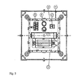
- FIG. 5 shows in plan view the support element (1), which further accommodates four boards (3), which are arranged in the support element (1), that they surround a rectangular area, Within this area are the said operating device (2), the electrical terminals ( 5, 6) and the accumulator (4).
- the boards (3) are each equipped with six LEDs and are fixed by in the support element (1) incorporated imprints in their position.
- each circuit board (3) is associated with a threaded constriction (11) at its end faces, with which a screw (10) cooperates.
- the screw (10) carries at least a first washer (13) which its associated Board overlaps. Now, when the screw (10) tightened, so presses the washer (13) on the board (3) and fixes them in this way in the support element.
- FIG. 3 two staggered by 90 degrees arranged boards (3) can be seen.
- the blanks (3) abut the front side at their inner corners,
- a shim (13 ') placed in such a way that it rests against the front side of each of the two boards (3).
- the washers (13 ') form a longitudinal stop for the boards (3).
- the mounting position of the boards (3) is thus exactly defined by the imprints in the carrier element (1) and by the washers (13 ').
- each of the Bailagin (13 ') has an inner diameter which is greater than the explicatenduranderesser the thread passage (11).
- the washers (13 ') can be placed over the respective Gewsnel matzug (11) and thus arranged in the correct position or centered in the housing, the washers (13') are higher by about 0.2 mm than the unpopulated board (3) - so only the circuit board itself - is.
- the shims (13 ') thus form a good support surface for lying over them washer (13) whose outer diameter is greater than the outer diameter of the shim (13'). That region, the shim (13) weleher on the shim (13 ') protrudes beyond the board (3) and holds the board (3) in this way in the support element (1) and secures and fixes them in their mounting position.
- the washers (13, 13 ') are made of plastic.
- the first washer (13) has an inside diameter of 4.3 mm and an outside diameter of 18.0 mm and is 2.0 mm high;
- the second washer (13 ') has an inner diameter of 5.2 mm and an outer diameter of 12.0 mm and is 2.0 mm high.
- the threaded passage (11) has an M4 internal thread; so that the screws (10) are M4 screws,
Landscapes
- Physics & Mathematics (AREA)
- General Physics & Mathematics (AREA)
- Engineering & Computer Science (AREA)
- Theoretical Computer Science (AREA)
- Fastening Of Light Sources Or Lamp Holders (AREA)
- Arrangement Of Elements, Cooling, Sealing, Or The Like Of Lighting Devices (AREA)
Abstract
Description
- Die Erfindung betrifft eine Leuchte nach dem Oberbegriff des Anspruchs 1. Die Leuchte besteht aus einem Gehäuse zur Aufnahme eines Betriebsgerätes und eines Leuchtmittels, Das Leuchtmittel ist aus Leuchtdioden (LED) gebildet, welche auf einer Platine angeordnet sind und die im Gehäuse mittels Schrauben fixiert ist. Hierzu ist es notwendig einen Aufnahmebereich in der Platine, also beispielsweise ein Lochung, für die Schraube vorzusehen.
- Alternative ist es aus dem Stand der Technik bekannt. LED-Platinen mittels einem speziellen doppelseitigem Klebeband auf einem dafür vorgesehenen Montageblech bzw in einem Leuchtengehäuse anzubringen. Durch die thermische Beanspruchung und wegen zu geringem Anpressdruck in der Montage kann es aber dazu kommen, dass sich der Kleber löst und die LED-Platine herunterhängt, Ein weiterer Nachteil der eben beschriebenen Methode ist die Ungenauigkeit mit welcher die LED-Platinen platziert werden.
- Der vorliegenden Erfindung liegt die Aufgabe zu Grunde eine Leuchte nach dem Oberbegriff des Anspruchs 1 so weiterzubilden, dass Leuchtmittel in Form von LED-Platinen einfach und zuverlässig sowie exakt montiert werden können.
- Die Aufgabe wird durch die kennzeichnenden Merkmale des Anspruchs 1 gelöst. Hierbei ist unmittelbar neben der Platine ein Qewindedurchzug vorgesehen, der eine Schraube aufnimmt welche eine ringförmige Beilagscheibe trägt, wobei diese Beilagscheibe teil weise die Platine übergreift, um die Platine im Cehäuse zu fixieren.
- Weiterbildungen der Erfindung sind in den Unteransprüchen angegeben. In einer bevorzugten Ausführungsform der Erfindung ist an beiden Stirnseiten der Platine ein Gewindedurchzug vorgesehen. Somit kann jeder der Gewindedurchzüge eine Schraube mit einer Beilagscheibe aufnchmen, um so ein übergreifen der Platine durch die beiden Beilagscheiben auf beiden Stirnseiten zu ermöglichen.
- Wenn das Gehäuse der Leuchte mehrere Platinen aufnimmt, können die Platinen beispielsweise so nebeneinander platziert sein, dass eine Schraube mit Beilagscheibe wenigstens zwei Platinen im Gehäuse fixiert.
- In einer besonders bevorzugten Ausführungsform der erfindungsgemäßcn Leuchte nimmt das Gehäuse vier Platinen auf, welche um 90 Grad versetzt angeordnet sind. Die so angeordneten Platinen umschließen ein Rechteck oder Quadrat.
- Um die lagegenaue Montage der Platinen in der erfindungsgemäßen Leuchte zu vereinfachen sind die Platinen seitlich vorzugsweise durch Anschläge geführt, welche insbesondere als Prägungen im Gehäuse abgebildet sein können. Außerdem kann vorgesehen sein, dass jede Schraube eine zweite Beilagscheibe aufnimmt, deren Außendurchmesser kleiner ist als der Außendurchmesser der ersten Beilagscheibe, wobei die zweite Beilagscheibe einen Längsanschlag für die Platine bildet. Vorzugsweise sind die Beilagscheiben als Kunststoffscheiben ausgeführt.
- Damit die zweite Beilagscheibe lagezentriert montiert werden kann, weist die zweite Beilagscheibe bevorzugt einen Innendurchmesser auf, der größer ist als der Außendurchmesser des Gewindedurchzuges. Die zweite Beilagscheibe wird in einer weiteren Ausführungsform um etwa 0,2 mm höher ausgeführt, als die Platine, damit kein zu großer Druck auf die, Platine ausgeübt werden kann, der zu einem Verkanten oder Verkippen der Platine bzw. Beilagscheibe führen könnte.
- Vorzugsweise ist die erfindungsgemäße Leuchte würfel- oder quaderförmig ausgeführt, wobei die Gehäuseoberseite aus einem aus Aluminiumblech gsfertigten Trägerelement gefertigt sein kann. Alle übrigen Gehäusewände sind bevorzugt aus lichtdurchlässigem Material, vorzugsweise Kunststoff, hergestellt. Die Gehäuseoberseite trägt die Platinen. Eine derartige Leuchte kann als so genannte Hinweise- der Notbeleuchtung ausgeführt werden. Für diesen Fall sind die Gehäusewände mit Piktogrammen beschichtet.
- Ein Ausführungsbeispiel der Erfindung wird anhand von Figuren genauer erläutert.
- Es zeigen:
-
Fig 1 eine perspektivische Ansicht einer erfindungsgemäßen Leuehte, -
Fig. 2 eine perspektivische Ansicht auf die Innenseite eines Trägerelementes einer Leuchte gemäßFig. 1 , -
Fig. 3 ein erstes Detail Y gemäßFig. 2 , -
Fig. 4 ein zweites Detail Z gemäßFig. 2 und -
Fig. 5 eine Draufsicht auf die Innenseite eines Trägerelements gemäßFig. 2 . - In
Figur 1 ist eine erfindungsgemäße Leuchte dargestellt. Diese besteht aus einer Gehäuseoberseite, die als aus Aluminiumblech gefertigtes Trägerelement (1) ausgeführt ist. Alle übrigen Gehäusewände (9) sind aus lichtdurchlässigem Material, vorzugsweise Kunststoff, beispielsweise aus 3 mm Starkem PMMA hergestellt. Wenn die Leuchte als Rettungszeichenleuchte ausgeführt ist, kann die Innenseite der Seitewände mit Rettungszeichen bedruckt sein. - Die Seitenwände sind mit dem Trägerelement (1) verschraubt und die Gehäuseunterseite ist mit den Seitenwänden verklebt. Im Gehäuseinneren kann auf der Gehäuseunterseite eine reflektierende Schicht (12) beispielsweise ein Aluminiumreflektor oder eine reflektierende Folie eingelegt werden, um das von den auf Platinen (3) angeordnete Leuchtdioden (LED) abgegebene Licht besser auf die Seitenwände zu verteilen.
- In
Figur 2 undFigur 5 ist das Trägerelement (1) dargestellt Dieses nimmt ein Betriebsgerät (2), elektrische Anschlussklemmen (5, 6) sowie einen Akkumulator (4), der im Notbetrieb für die Stromversorgung der Leuchte sorgt, auf Die Funktionsfähigkeit sowie der Ladestatus des Akkumulators (4) muss angezeigt werden. Dies erfolgt mit einer Status-LED (7), welche an einer Seitenwand angebracht ist und die stark genug leuchtet, um durch die Seitenwand hindurch zu leuchten um wahrnehmbar zu sein. Die reguläre Stromversorgung erfolgt über Stromkabel, die durch Einspeisetüllen (8) in das Gehäuseinnere geführt werden können. -
Figur 5 zeigt in Draufsicht das Trägerelement (1), welches weiters vier Platinen (3) aufnimmt, die so im Trägerelement (1) angeordnet sind, dass sie eine rechteckige Fläche umschließen, Innerhalb dieser Fläche sind das besagte Betriebsgerät (2), die elektrische Anschlussklemmen (5, 6) sowie der Akkumulator (4) angeordnet. Die Platinen (3) sind jeweils mit sechs Leuchtdioden bestückt und werden von in das Trägerelement (1) eingearbeitete Prägungen in ihrer Lage fixiert. Zur vollen Fixierung ist jeder Platine (3) an deren Stirnseiten ein Gewindedurehzug (11) zugeordnet, mit dem eine Schraube (10) zusammenwirkt. Die Schraube (10) trägt wenigstens eine erste Beilagscheibe (13), welche die ihr zugeordnete Platine übergreift. Wird nun die Schraube (10) angezogen, so drückt die Beilagscheibe (13) auf die Platine (3) und fixiert diese auf diese Weise im Trägerelement. - In
Figur 3 sind zwei um 90 Grad versetzt angeordnet Platinen (3) erkennbar. Die Platinen (3) stoßen stirnseitig an ihren inneren Ecken zusammen, Im stirnseitigen Bereich dieser beiden Platinen (3) ist eine Beilagescheibe (13') in der Weise platziert, dass diese an der Stirnseite einer jeden der beiden Platinen (3) anliegt. Die Beilagscheiben (13') bilden einen Längsanschlag für die Platinen (3). Die Montageposition der Platinen (3) ist somit durch die Prägungen im Trägerelement (1) sowie durch die Beilagscheiben (13') exakt definiert. - Insbesondere in
Figur 4 ist erkennbar, dsss die Öffnung jeder der Bailagscheiben (13') einen Innendurchmesser aufweist, der größer ist als der Außendurehmesser des Gewindedurchzuges (11). Somit können die Beilagscheiben (13') über den jeweiligen Gewsndedurchzug (11) gesteckt und damit lagerichtig bzw. zentriert im Gehäuse angeordnet werden, Die Beilagscheiben (13') sind um etwa 0,2 mm höher als es die unbestückte Platine (3) - also nur die Leiterplatte an sich - ist. Die Beilagescheiben (13') bilden somit eine gute Auflagefläche für über ihnen liegende Beilagscheibe (13), deren Außendurchmesser größer ist, als der Außendurchmesser der Beilagescheibe (13'). Jener Bereich, der Beilagescheibe (13) weleher über die Beilagescheibe (13') hinaus ragt, übergreift die Platine (3) und hält die platine (3) auf diese Weise im Trägerelement (1) und sichert und fixert diese in ihrer Montageposition. - Die Beilagscheiben (13, 13') sind aus Kunststoff gefertigt. Die erste Beilagscheibe (13) weist einen Innendurehmesser von 4,3 mm und einen Außendurchmesser von 18,0 mm auf und ist 2,0 mm hoch; die zweite Beilagscheibe (13') hat einen Innendurchmesser von 5,2 mm und einen Außendurchmesser von 12,0 mm auf und ist 2,0 mm hoch. Der Gewindedurchzug (11) weist ein M4-Innengewinde auf; damit sind die Schrauben (10) M4-Schrauben,
Claims (10)
- Leuchte mit Gehäuse zur Aufnahme eines Betriebsgerätes und eines Leuchtmittels, wobei das Leuchtmittel aus Leuchtdioden (LED) gebildet ist, weiche auf einer Platine angeordnet sind und die im Gehäuse mittels Schrauben fixiert ist,
dadurch gekennzeichnet,
dass unmittelbar neben der Platine (3) ein Gewindedurchzug (11) vorgesehen ist, der eine Schraube (10) aufnimmt und dass die Schraube (10) eine ringförmige Beilagscheibe (13) trägt, wobei diese teilweise die Platine (3) übergreift, um diese im Gehäuse zu fixieren. - Leuchte nach Anspruch 1,
dadurch gekennzeichnet,
dass an beiden Stimseiten der Platine ein Gawindedurchzug (11) vorgesehen ist, dass jeder der Gewindedurchzüge (11) eine Schraube (10) mit einer Beilagscheibe (13) aufnimmt, wobei die Beilagschreiben die Platine (3) stirnseitig übergreifen. - Leuchte nach Anspruch 1 oder 2,
dadurch gekennzeichnet,
dass das Gehäuse mehrere Platinen (3) aufnimmt und dass die Platinen (3) so nebeneinander platziert sind, dass eine Schraube (10) mit Beilagscheibe (13) wenigstens zwei Platinen (3) im Gehäuse fixiert. - Leuchte nach Anspruch 1, 2 oder 3,
dadurch gekennzeichnet,
dass das Gehäuse vier Platinen (3) aufnimmt und dass die Platinen um 90 Grad versetzt angeordnet sind. - Leuchte nach einem der vorigen Ansprüche,
dadurch gekennzeichnet,
dass die Platinen (3) seitlich durch Anschläge, insbesondere Prägungen im Gehäuse, geführt sind. - Leuchte nach einem der vorigen Ansprüche,
dadurch gekennzeichnet,
dass jede Schraube eine zweite Beilagscheibe (13') aufnimmt, deren Außendurchmesser kleiner ist als der Außendurehmesser der ersten Beilagscheibe (13), wobei die zweite Beilagscheibe (13') einen Längsansehlag für die Platine biläet. - Leuchte nach einem der vorigen Ansprüche,
dadurch gekennzeichnet,
dass die Beilagscheiben (13, 13') als Kunststoffscheiben ausgeführt sind. - Leuchte nach einem der vorigen Ansprüche,
dadurch gekennzeichnet,
dass die zweite Beilagscheibe (13') einen Innendurchmesser aufweist der größer ist als der Außendurchmesser des Gewindedurchzuges (11). - Leuchte nach einem der vorigen Ansprüche,
dadurch gekennzeichnet,
dass die zweite Beilagscheibe (13') um etwa 0,2 mm höher ist, als die Platinen (3). - Leuchte nach einem der vorigen Ansprüche,
dadruch gekennzeichnet,
dass die Leuchte würfel- oder quaderförmig ist,
dass die Gehäuseobersefte als aus Aluminiumblech gefertigtes Trägerelement (1) ausgeführt ist, dass alle übrigen Gehäusewände (9) aus lichtdurchlässigem Material, vorzugsweise Kunststoff hergestellt sind und dass das Trägerelement die Platinen (3), das Betriebsgerät (2) und elektrische Anschlussklemmen (5,6) trägt.
Applications Claiming Priority (1)
| Application Number | Priority Date | Filing Date | Title |
|---|---|---|---|
| ATGM139/2012U AT13301U1 (de) | 2012-04-12 | 2012-04-12 | Leuchte mit Leuchtdiode |
Publications (3)
| Publication Number | Publication Date |
|---|---|
| EP2650864A2 true EP2650864A2 (de) | 2013-10-16 |
| EP2650864A3 EP2650864A3 (de) | 2014-05-07 |
| EP2650864B1 EP2650864B1 (de) | 2018-07-04 |
Family
ID=48141718
Family Applications (1)
| Application Number | Title | Priority Date | Filing Date |
|---|---|---|---|
| EP13001928.4A Not-in-force EP2650864B1 (de) | 2012-04-12 | 2013-04-12 | Leuchte mit Leuchtdioden |
Country Status (2)
| Country | Link |
|---|---|
| EP (1) | EP2650864B1 (de) |
| AT (1) | AT13301U1 (de) |
Family Cites Families (5)
| Publication number | Priority date | Publication date | Assignee | Title |
|---|---|---|---|---|
| DE19621254B4 (de) * | 1996-05-25 | 2007-07-12 | Automotive Lighting Reutlingen Gmbh | Fahrzeugscheinwerfer |
| JP3852687B2 (ja) * | 2002-01-08 | 2006-12-06 | 松下電工株式会社 | 表示用照明器具 |
| JP4315042B2 (ja) * | 2004-04-09 | 2009-08-19 | パナソニック電工株式会社 | 照明器具及びこれを用いた照明装置 |
| JP5072568B2 (ja) * | 2007-12-18 | 2012-11-14 | 三菱電機株式会社 | Led照明装置 |
| JP2009283140A (ja) * | 2008-05-19 | 2009-12-03 | Sharp Corp | 光源モジュール及び照明装置 |
-
2012
- 2012-04-12 AT ATGM139/2012U patent/AT13301U1/de not_active IP Right Cessation
-
2013
- 2013-04-12 EP EP13001928.4A patent/EP2650864B1/de not_active Not-in-force
Also Published As
| Publication number | Publication date |
|---|---|
| AT13301U1 (de) | 2013-10-15 |
| EP2650864B1 (de) | 2018-07-04 |
| EP2650864A3 (de) | 2014-05-07 |
Similar Documents
| Publication | Publication Date | Title |
|---|---|---|
| DE102012109700B4 (de) | LED-Warnleuchte | |
| EP2863114B1 (de) | LED-Flächenleuchte | |
| DE102012023190A1 (de) | Signalsäule | |
| EP2743564B1 (de) | Beleuchtungseinrichtung und Beleuchtungsanordnung zum Beleuchten des Innenraumes eines Turmes oder Tunnels | |
| EP2765445A1 (de) | LED-Einheit mit Linse | |
| AT13183U1 (de) | Linsenhalter für leds | |
| DE202011107787U1 (de) | Lichtemissionsvorrichtung | |
| DE102013109890A1 (de) | Flexibles LED-Lichtquellenmodul | |
| DE102007009229B4 (de) | Lichtquelle zur Simulation einer Punktlichtquelle, sowie Leuchte mit einer derartigen Lichtquelle | |
| EP2561725B1 (de) | Led-modul mit passiv-led | |
| DE112013005283T5 (de) | Beleuchtungsvorrichtung | |
| DE202012009636U1 (de) | Beleuchtungssystem mit einem Leuchtmittel | |
| AT13039U1 (de) | Reflektoreinheit für leds, led lichtquelle, poster-box sowie verfahren zur montage der led lichtquelle | |
| EP2650864B1 (de) | Leuchte mit Leuchtdioden | |
| WO2020057765A1 (de) | Lichtemittierende vorrichtung und verfahren zum herstellen derselben | |
| DE102010028416A1 (de) | LED-Modul mit Linse zum Erzeugen einer nicht rotationssymmetrischen Lichtverteilung | |
| EP2245362B1 (de) | Beleuchtungseinrichtung | |
| DE112021003290T5 (de) | Signalbeleuchtungseinrichtung eines Kraftfahrzeuges | |
| DE202012101344U1 (de) | Beleuchtungseinrichtung und LED-Beleuchtungssystem | |
| DE102015106421A1 (de) | Beleuchtungslichtquelle und Beleuchtungsvorrichtung | |
| AT15392U1 (de) | Wannenleuchte | |
| DE102010042727A1 (de) | OLED-Modul | |
| DE102008047406A1 (de) | Folientastatur mit beleuchtetem Anzeigeelement | |
| DE202012011371U1 (de) | Signalsäule | |
| DE102019126892A1 (de) | Positionierung eines silikonlinsenkörpers an einer led |
Legal Events
| Date | Code | Title | Description |
|---|---|---|---|
| PUAI | Public reference made under article 153(3) epc to a published international application that has entered the european phase |
Free format text: ORIGINAL CODE: 0009012 |
|
| AK | Designated contracting states |
Kind code of ref document: A2 Designated state(s): AL AT BE BG CH CY CZ DE DK EE ES FI FR GB GR HR HU IE IS IT LI LT LU LV MC MK MT NL NO PL PT RO RS SE SI SK SM TR |
|
| AX | Request for extension of the european patent |
Extension state: BA ME |
|
| PUAL | Search report despatched |
Free format text: ORIGINAL CODE: 0009013 |
|
| AK | Designated contracting states |
Kind code of ref document: A3 Designated state(s): AL AT BE BG CH CY CZ DE DK EE ES FI FR GB GR HR HU IE IS IT LI LT LU LV MC MK MT NL NO PL PT RO RS SE SI SK SM TR |
|
| AX | Request for extension of the european patent |
Extension state: BA ME |
|
| RIC1 | Information provided on ipc code assigned before grant |
Ipc: G09F 13/04 20060101AFI20140328BHEP Ipc: G09F 13/22 20060101ALI20140328BHEP |
|
| 17P | Request for examination filed |
Effective date: 20141107 |
|
| RBV | Designated contracting states (corrected) |
Designated state(s): AL AT BE BG CH CY CZ DE DK EE ES FI FR GB GR HR HU IE IS IT LI LT LU LV MC MK MT NL NO PL PT RO RS SE SI SK SM TR |
|
| GRAP | Despatch of communication of intention to grant a patent |
Free format text: ORIGINAL CODE: EPIDOSNIGR1 |
|
| STAA | Information on the status of an ep patent application or granted ep patent |
Free format text: STATUS: GRANT OF PATENT IS INTENDED |
|
| INTG | Intention to grant announced |
Effective date: 20180322 |
|
| GRAS | Grant fee paid |
Free format text: ORIGINAL CODE: EPIDOSNIGR3 |
|
| GRAA | (expected) grant |
Free format text: ORIGINAL CODE: 0009210 |
|
| STAA | Information on the status of an ep patent application or granted ep patent |
Free format text: STATUS: THE PATENT HAS BEEN GRANTED |
|
| AK | Designated contracting states |
Kind code of ref document: B1 Designated state(s): AL AT BE BG CH CY CZ DE DK EE ES FI FR GB GR HR HU IE IS IT LI LT LU LV MC MK MT NL NO PL PT RO RS SE SI SK SM TR |
|
| REG | Reference to a national code |
Ref country code: GB Ref legal event code: FG4D Free format text: NOT ENGLISH |
|
| REG | Reference to a national code |
Ref country code: CH Ref legal event code: EP |
|
| REG | Reference to a national code |
Ref country code: AT Ref legal event code: REF Ref document number: 1015339 Country of ref document: AT Kind code of ref document: T Effective date: 20180715 |
|
| REG | Reference to a national code |
Ref country code: IE Ref legal event code: FG4D Free format text: LANGUAGE OF EP DOCUMENT: GERMAN |
|
| REG | Reference to a national code |
Ref country code: DE Ref legal event code: R096 Ref document number: 502013010516 Country of ref document: DE |
|
| REG | Reference to a national code |
Ref country code: CH Ref legal event code: NV Representative=s name: FELBER UND PARTNER AG, CH |
|
| REG | Reference to a national code |
Ref country code: NL Ref legal event code: MP Effective date: 20180704 |
|
| REG | Reference to a national code |
Ref country code: LT Ref legal event code: MG4D |
|
| PG25 | Lapsed in a contracting state [announced via postgrant information from national office to epo] |
Ref country code: NL Free format text: LAPSE BECAUSE OF FAILURE TO SUBMIT A TRANSLATION OF THE DESCRIPTION OR TO PAY THE FEE WITHIN THE PRESCRIBED TIME-LIMIT Effective date: 20180704 |
|
| PG25 | Lapsed in a contracting state [announced via postgrant information from national office to epo] |
Ref country code: BG Free format text: LAPSE BECAUSE OF FAILURE TO SUBMIT A TRANSLATION OF THE DESCRIPTION OR TO PAY THE FEE WITHIN THE PRESCRIBED TIME-LIMIT Effective date: 20181004 Ref country code: NO Free format text: LAPSE BECAUSE OF FAILURE TO SUBMIT A TRANSLATION OF THE DESCRIPTION OR TO PAY THE FEE WITHIN THE PRESCRIBED TIME-LIMIT Effective date: 20181004 Ref country code: IS Free format text: LAPSE BECAUSE OF FAILURE TO SUBMIT A TRANSLATION OF THE DESCRIPTION OR TO PAY THE FEE WITHIN THE PRESCRIBED TIME-LIMIT Effective date: 20181104 Ref country code: RS Free format text: LAPSE BECAUSE OF FAILURE TO SUBMIT A TRANSLATION OF THE DESCRIPTION OR TO PAY THE FEE WITHIN THE PRESCRIBED TIME-LIMIT Effective date: 20180704 Ref country code: GR Free format text: LAPSE BECAUSE OF FAILURE TO SUBMIT A TRANSLATION OF THE DESCRIPTION OR TO PAY THE FEE WITHIN THE PRESCRIBED TIME-LIMIT Effective date: 20181005 Ref country code: PL Free format text: LAPSE BECAUSE OF FAILURE TO SUBMIT A TRANSLATION OF THE DESCRIPTION OR TO PAY THE FEE WITHIN THE PRESCRIBED TIME-LIMIT Effective date: 20180704 Ref country code: SE Free format text: LAPSE BECAUSE OF FAILURE TO SUBMIT A TRANSLATION OF THE DESCRIPTION OR TO PAY THE FEE WITHIN THE PRESCRIBED TIME-LIMIT Effective date: 20180704 Ref country code: FI Free format text: LAPSE BECAUSE OF FAILURE TO SUBMIT A TRANSLATION OF THE DESCRIPTION OR TO PAY THE FEE WITHIN THE PRESCRIBED TIME-LIMIT Effective date: 20180704 Ref country code: LT Free format text: LAPSE BECAUSE OF FAILURE TO SUBMIT A TRANSLATION OF THE DESCRIPTION OR TO PAY THE FEE WITHIN THE PRESCRIBED TIME-LIMIT Effective date: 20180704 Ref country code: CZ Free format text: LAPSE BECAUSE OF FAILURE TO SUBMIT A TRANSLATION OF THE DESCRIPTION OR TO PAY THE FEE WITHIN THE PRESCRIBED TIME-LIMIT Effective date: 20180704 |
|
| PG25 | Lapsed in a contracting state [announced via postgrant information from national office to epo] |
Ref country code: ES Free format text: LAPSE BECAUSE OF FAILURE TO SUBMIT A TRANSLATION OF THE DESCRIPTION OR TO PAY THE FEE WITHIN THE PRESCRIBED TIME-LIMIT Effective date: 20180704 Ref country code: AL Free format text: LAPSE BECAUSE OF FAILURE TO SUBMIT A TRANSLATION OF THE DESCRIPTION OR TO PAY THE FEE WITHIN THE PRESCRIBED TIME-LIMIT Effective date: 20180704 Ref country code: LV Free format text: LAPSE BECAUSE OF FAILURE TO SUBMIT A TRANSLATION OF THE DESCRIPTION OR TO PAY THE FEE WITHIN THE PRESCRIBED TIME-LIMIT Effective date: 20180704 Ref country code: HR Free format text: LAPSE BECAUSE OF FAILURE TO SUBMIT A TRANSLATION OF THE DESCRIPTION OR TO PAY THE FEE WITHIN THE PRESCRIBED TIME-LIMIT Effective date: 20180704 |
|
| REG | Reference to a national code |
Ref country code: DE Ref legal event code: R097 Ref document number: 502013010516 Country of ref document: DE |
|
| PG25 | Lapsed in a contracting state [announced via postgrant information from national office to epo] |
Ref country code: EE Free format text: LAPSE BECAUSE OF FAILURE TO SUBMIT A TRANSLATION OF THE DESCRIPTION OR TO PAY THE FEE WITHIN THE PRESCRIBED TIME-LIMIT Effective date: 20180704 Ref country code: IT Free format text: LAPSE BECAUSE OF FAILURE TO SUBMIT A TRANSLATION OF THE DESCRIPTION OR TO PAY THE FEE WITHIN THE PRESCRIBED TIME-LIMIT Effective date: 20180704 Ref country code: RO Free format text: LAPSE BECAUSE OF FAILURE TO SUBMIT A TRANSLATION OF THE DESCRIPTION OR TO PAY THE FEE WITHIN THE PRESCRIBED TIME-LIMIT Effective date: 20180704 |
|
| PLBE | No opposition filed within time limit |
Free format text: ORIGINAL CODE: 0009261 |
|
| STAA | Information on the status of an ep patent application or granted ep patent |
Free format text: STATUS: NO OPPOSITION FILED WITHIN TIME LIMIT |
|
| PG25 | Lapsed in a contracting state [announced via postgrant information from national office to epo] |
Ref country code: SK Free format text: LAPSE BECAUSE OF FAILURE TO SUBMIT A TRANSLATION OF THE DESCRIPTION OR TO PAY THE FEE WITHIN THE PRESCRIBED TIME-LIMIT Effective date: 20180704 Ref country code: DK Free format text: LAPSE BECAUSE OF FAILURE TO SUBMIT A TRANSLATION OF THE DESCRIPTION OR TO PAY THE FEE WITHIN THE PRESCRIBED TIME-LIMIT Effective date: 20180704 Ref country code: SM Free format text: LAPSE BECAUSE OF FAILURE TO SUBMIT A TRANSLATION OF THE DESCRIPTION OR TO PAY THE FEE WITHIN THE PRESCRIBED TIME-LIMIT Effective date: 20180704 |
|
| 26N | No opposition filed |
Effective date: 20190405 |
|
| PG25 | Lapsed in a contracting state [announced via postgrant information from national office to epo] |
Ref country code: SI Free format text: LAPSE BECAUSE OF FAILURE TO SUBMIT A TRANSLATION OF THE DESCRIPTION OR TO PAY THE FEE WITHIN THE PRESCRIBED TIME-LIMIT Effective date: 20180704 |
|
| PGFP | Annual fee paid to national office [announced via postgrant information from national office to epo] |
Ref country code: CH Payment date: 20190426 Year of fee payment: 7 |
|
| PGFP | Annual fee paid to national office [announced via postgrant information from national office to epo] |
Ref country code: IE Payment date: 20190410 Year of fee payment: 6 |
|
| REG | Reference to a national code |
Ref country code: BE Ref legal event code: MM Effective date: 20190430 |
|
| PG25 | Lapsed in a contracting state [announced via postgrant information from national office to epo] |
Ref country code: MC Free format text: LAPSE BECAUSE OF FAILURE TO SUBMIT A TRANSLATION OF THE DESCRIPTION OR TO PAY THE FEE WITHIN THE PRESCRIBED TIME-LIMIT Effective date: 20180704 Ref country code: LU Free format text: LAPSE BECAUSE OF NON-PAYMENT OF DUE FEES Effective date: 20190412 |
|
| REG | Reference to a national code |
Ref country code: DE Ref legal event code: R084 Ref document number: 502013010516 Country of ref document: DE |
|
| PG25 | Lapsed in a contracting state [announced via postgrant information from national office to epo] |
Ref country code: BE Free format text: LAPSE BECAUSE OF NON-PAYMENT OF DUE FEES Effective date: 20190430 |
|
| PG25 | Lapsed in a contracting state [announced via postgrant information from national office to epo] |
Ref country code: TR Free format text: LAPSE BECAUSE OF FAILURE TO SUBMIT A TRANSLATION OF THE DESCRIPTION OR TO PAY THE FEE WITHIN THE PRESCRIBED TIME-LIMIT Effective date: 20180704 |
|
| PG25 | Lapsed in a contracting state [announced via postgrant information from national office to epo] |
Ref country code: IE Free format text: LAPSE BECAUSE OF NON-PAYMENT OF DUE FEES Effective date: 20190412 |
|
| PG25 | Lapsed in a contracting state [announced via postgrant information from national office to epo] |
Ref country code: PT Free format text: LAPSE BECAUSE OF FAILURE TO SUBMIT A TRANSLATION OF THE DESCRIPTION OR TO PAY THE FEE WITHIN THE PRESCRIBED TIME-LIMIT Effective date: 20181105 |
|
| REG | Reference to a national code |
Ref country code: CH Ref legal event code: PL |
|
| REG | Reference to a national code |
Ref country code: AT Ref legal event code: MM01 Ref document number: 1015339 Country of ref document: AT Kind code of ref document: T Effective date: 20200412 |
|
| PG25 | Lapsed in a contracting state [announced via postgrant information from national office to epo] |
Ref country code: LI Free format text: LAPSE BECAUSE OF NON-PAYMENT OF DUE FEES Effective date: 20200430 Ref country code: CH Free format text: LAPSE BECAUSE OF NON-PAYMENT OF DUE FEES Effective date: 20200430 Ref country code: AT Free format text: LAPSE BECAUSE OF NON-PAYMENT OF DUE FEES Effective date: 20200412 |
|
| PG25 | Lapsed in a contracting state [announced via postgrant information from national office to epo] |
Ref country code: CY Free format text: LAPSE BECAUSE OF FAILURE TO SUBMIT A TRANSLATION OF THE DESCRIPTION OR TO PAY THE FEE WITHIN THE PRESCRIBED TIME-LIMIT Effective date: 20180704 |
|
| PG25 | Lapsed in a contracting state [announced via postgrant information from national office to epo] |
Ref country code: MT Free format text: LAPSE BECAUSE OF FAILURE TO SUBMIT A TRANSLATION OF THE DESCRIPTION OR TO PAY THE FEE WITHIN THE PRESCRIBED TIME-LIMIT Effective date: 20180704 Ref country code: HU Free format text: LAPSE BECAUSE OF FAILURE TO SUBMIT A TRANSLATION OF THE DESCRIPTION OR TO PAY THE FEE WITHIN THE PRESCRIBED TIME-LIMIT; INVALID AB INITIO Effective date: 20130412 |
|
| PG25 | Lapsed in a contracting state [announced via postgrant information from national office to epo] |
Ref country code: MK Free format text: LAPSE BECAUSE OF FAILURE TO SUBMIT A TRANSLATION OF THE DESCRIPTION OR TO PAY THE FEE WITHIN THE PRESCRIBED TIME-LIMIT Effective date: 20180704 |
|
| PGFP | Annual fee paid to national office [announced via postgrant information from national office to epo] |
Ref country code: GB Payment date: 20220419 Year of fee payment: 10 Ref country code: FR Payment date: 20220427 Year of fee payment: 10 |
|
| P01 | Opt-out of the competence of the unified patent court (upc) registered |
Effective date: 20230530 |
|
| PGFP | Annual fee paid to national office [announced via postgrant information from national office to epo] |
Ref country code: DE Payment date: 20230427 Year of fee payment: 11 |
|
| GBPC | Gb: european patent ceased through non-payment of renewal fee |
Effective date: 20230412 |
|
| PG25 | Lapsed in a contracting state [announced via postgrant information from national office to epo] |
Ref country code: GB Free format text: LAPSE BECAUSE OF NON-PAYMENT OF DUE FEES Effective date: 20230412 |
|
| PG25 | Lapsed in a contracting state [announced via postgrant information from national office to epo] |
Ref country code: GB Free format text: LAPSE BECAUSE OF NON-PAYMENT OF DUE FEES Effective date: 20230412 Ref country code: FR Free format text: LAPSE BECAUSE OF NON-PAYMENT OF DUE FEES Effective date: 20230430 |
|
| REG | Reference to a national code |
Ref country code: DE Ref legal event code: R119 Ref document number: 502013010516 Country of ref document: DE |
|
| PG25 | Lapsed in a contracting state [announced via postgrant information from national office to epo] |
Ref country code: DE Free format text: LAPSE BECAUSE OF NON-PAYMENT OF DUE FEES Effective date: 20241105 |
|
| PG25 | Lapsed in a contracting state [announced via postgrant information from national office to epo] |
Ref country code: DE Free format text: LAPSE BECAUSE OF NON-PAYMENT OF DUE FEES Effective date: 20241105 |