EP2650849A2 - Einbau-Passiv-Infrarot-Sensorvorrichtung - Google Patents
Einbau-Passiv-Infrarot-Sensorvorrichtung Download PDFInfo
- Publication number
- EP2650849A2 EP2650849A2 EP13153551.0A EP13153551A EP2650849A2 EP 2650849 A2 EP2650849 A2 EP 2650849A2 EP 13153551 A EP13153551 A EP 13153551A EP 2650849 A2 EP2650849 A2 EP 2650849A2
- Authority
- EP
- European Patent Office
- Prior art keywords
- housing
- contour
- sensor device
- parallel
- section
- Prior art date
- Legal status (The legal status is an assumption and is not a legal conclusion. Google has not performed a legal analysis and makes no representation as to the accuracy of the status listed.)
- Granted
Links
Images


Classifications
-
- G—PHYSICS
- G08—SIGNALLING
- G08B—SIGNALLING SYSTEMS, e.g. PERSONAL CALLING SYSTEMS; ORDER TELEGRAPHS; ALARM SYSTEMS
- G08B13/00—Burglar, theft or intruder alarms
- G08B13/18—Actuation by interference with heat, light, or radiation of shorter wavelength; Actuation by intruding sources of heat, light, or radiation of shorter wavelength
- G08B13/189—Actuation by interference with heat, light, or radiation of shorter wavelength; Actuation by intruding sources of heat, light, or radiation of shorter wavelength using passive radiation detection systems
- G08B13/19—Actuation by interference with heat, light, or radiation of shorter wavelength; Actuation by intruding sources of heat, light, or radiation of shorter wavelength using passive radiation detection systems using infrared-radiation detection systems
-
- G—PHYSICS
- G01—MEASURING; TESTING
- G01J—MEASUREMENT OF INTENSITY, VELOCITY, SPECTRAL CONTENT, POLARISATION, PHASE OR PULSE CHARACTERISTICS OF INFRARED, VISIBLE OR ULTRAVIOLET LIGHT; COLORIMETRY; RADIATION PYROMETRY
- G01J5/00—Radiation pyrometry, e.g. infrared or optical thermometry
- G01J5/0022—Radiation pyrometry, e.g. infrared or optical thermometry for sensing the radiation of moving bodies
-
- G—PHYSICS
- G01—MEASURING; TESTING
- G01J—MEASUREMENT OF INTENSITY, VELOCITY, SPECTRAL CONTENT, POLARISATION, PHASE OR PULSE CHARACTERISTICS OF INFRARED, VISIBLE OR ULTRAVIOLET LIGHT; COLORIMETRY; RADIATION PYROMETRY
- G01J5/00—Radiation pyrometry, e.g. infrared or optical thermometry
- G01J5/02—Constructional details
- G01J5/0205—Mechanical elements; Supports for optical elements
-
- G—PHYSICS
- G01—MEASURING; TESTING
- G01J—MEASUREMENT OF INTENSITY, VELOCITY, SPECTRAL CONTENT, POLARISATION, PHASE OR PULSE CHARACTERISTICS OF INFRARED, VISIBLE OR ULTRAVIOLET LIGHT; COLORIMETRY; RADIATION PYROMETRY
- G01J5/00—Radiation pyrometry, e.g. infrared or optical thermometry
- G01J5/02—Constructional details
- G01J5/04—Casings
-
- G—PHYSICS
- G01—MEASURING; TESTING
- G01J—MEASUREMENT OF INTENSITY, VELOCITY, SPECTRAL CONTENT, POLARISATION, PHASE OR PULSE CHARACTERISTICS OF INFRARED, VISIBLE OR ULTRAVIOLET LIGHT; COLORIMETRY; RADIATION PYROMETRY
- G01J5/00—Radiation pyrometry, e.g. infrared or optical thermometry
- G01J5/02—Constructional details
- G01J5/07—Arrangements for adjusting the solid angle of collected radiation, e.g. adjusting or orienting field of view, tracking position or encoding angular position
-
- G—PHYSICS
- G01—MEASURING; TESTING
- G01J—MEASUREMENT OF INTENSITY, VELOCITY, SPECTRAL CONTENT, POLARISATION, PHASE OR PULSE CHARACTERISTICS OF INFRARED, VISIBLE OR ULTRAVIOLET LIGHT; COLORIMETRY; RADIATION PYROMETRY
- G01J5/00—Radiation pyrometry, e.g. infrared or optical thermometry
- G01J5/02—Constructional details
- G01J5/08—Optical arrangements
- G01J5/0806—Focusing or collimating elements, e.g. lenses or concave mirrors
-
- H—ELECTRICITY
- H02—GENERATION; CONVERSION OR DISTRIBUTION OF ELECTRIC POWER
- H02G—INSTALLATION OF ELECTRIC CABLES OR LINES, OR OF COMBINED OPTICAL AND ELECTRIC CABLES OR LINES
- H02G3/00—Installations of electric cables or lines or protective tubing therefor in or on buildings, equivalent structures or vehicles
- H02G3/02—Details
- H02G3/08—Distribution boxes; Connection or junction boxes
- H02G3/12—Distribution boxes; Connection or junction boxes for flush mounting
- H02G3/123—Distribution boxes; Connection or junction boxes for flush mounting in thin walls
-
- H—ELECTRICITY
- H02—GENERATION; CONVERSION OR DISTRIBUTION OF ELECTRIC POWER
- H02G—INSTALLATION OF ELECTRIC CABLES OR LINES, OR OF COMBINED OPTICAL AND ELECTRIC CABLES OR LINES
- H02G3/00—Installations of electric cables or lines or protective tubing therefor in or on buildings, equivalent structures or vehicles
- H02G3/02—Details
- H02G3/08—Distribution boxes; Connection or junction boxes
- H02G3/18—Distribution boxes; Connection or junction boxes providing line outlets
- H02G3/20—Ceiling roses or other lighting sets
Definitions
- the invention relates to a built-passive infrared sensor device for use as motion and / or presence detector according to claim 1.
- the invention relates to a flush-mounted PIR sensor device.
- PIR sensor devices as motion detectors and / or as presence detectors are well known. These usually designed as surface-mounted sensor devices devices usually have a circular or geometrically undefined detection area, which is particularly problematic in large rooms or elongated corridors to divide the space as completely as possible in different detection areas without the detection areas for monitoring the room or corridor necessary majority of sensor devices overlap in large areas. This makes it difficult to realize a defined location-dependent activation of different consumers.
- the invention has for its object to provide an improved PIR sensor device, by means of which large areas are monitored as completely as possible, the sensor device should preferably be as easy to assemble or align. At the same time, the sensor device should be aesthetically pleasing, i. be designed as flat as possible in a range detectable by the viewer.
- the invention is based first of the idea, the plurality of individual lenses and / or lens sections exhibiting, even more preferably designed as a plastic injection molded part surface lens arrangement such or calculate that of this one in one, preferably in one Parallel plane to the surface extension of the surface lens assembly and at a distance from this arranged, detection plane arranged detection range can be monitored, which has a Hüllkontur with at least two parallel Hüllkonturkanten.
- the areal lens arrangement is preferably designed such that this detection area has an envelope contour, in particular a honeycomb or hexagon contour, a rectangular contour or particularly preferably a square contour, which makes it possible to subdivide a large area completely into a plurality of such detection areas without the detection areas have to overlap to ensure that movements in defined areas result in defined detection position-dependent activations of consumers that can be activated by the sensor device.
- the two parallel first hull contour edges (on a reduced scale) on the housing reside as two parallel first housing contour sections, in particular peripheral peripheral contour sections, these two parallel first, preferably arranged in a common cross-sectional plane housing contour portions, which are formed for example by two parallel housing side surfaces and / or two parallel housing side edges are aligned parallel to the first Hüllkonturkanten so that the position of the detection plane on the housing contour of the sensor device is readable, so that the fitter Align the housing directly to align the detection area and detect this orientation on the housing orientation.
- the sensor device as a built-in passive infrared sensor device, in particular as a flush PIR sensor device whose housing is at least partially, in particular mostly with an installation section in or behind a ceiling or wall mounting opening, preferably having a standard diameter of 50 mm, retractable so that visible on the ceiling or wall only a viewing portion remains, which can then have a very small height extension, so that at least to the viewer of the impression arises, the entire sensor has an extremely flat design.
- the at least one, preferably exclusively a PIR sensor unit, with Distance to the lenslet array must be arranged, is preferably in the retractable mounting portion, so that the necessary to be maintained for proceedingsnlinsenanssen focal length distance, the height extent of the viewing section, measured perpendicular to the ceiling or wall, not adversely affected.
- the detection plane in which the detection area is arranged is spaced from the sensor device, in particular over a typical room height from a range between 2 and 5 m, and parallel to the mounting surface (ceiling or wall) and thus parallel to the contact surface of the viewing section, with which this can rest on the ceiling or wall, aligned.
- the housing contour in particular the circumferential contour of at least one housing section of the sensor housing, in particular the viewing section and / or the mounting section (on a reduced scale), at least approximately corresponds to the envelope contour of the detection area in the detection plane, wherein the housing peripheral contour to the envelope contour of the detection range is aligned, such that the orientation of the envelope contour of the detection range corresponds to the orientation of the housing peripheral contour.
- the corresponding (to scale different) contour sections of housing and detection area are aligned parallel to each other.
- the circumferential contour of the housing, as well as the envelope contour of the detection area is honeycomb, rectangular or very particularly preferably square, ie such that a large area can be completely covered by juxtaposing different (identical) detection areas without the detection areas have to overlap, so again defined activations of different sensor devices associated with the detection areas are ensured.
- first and / or second housing contour sections which are preferably located in a common cross-sectional plane of the housing
- first and second housing contour sections preferably in a common cross-sectional plane
- an arrangement of such housing contour sections on the mounting portion is possible, in which case the alignment of the detection area on the housing contour is read only in the assembly, since the mounting portion is sunk in the assembled state in the mounting hole.
- the housing peripheral contour corresponds at least approximately to the envelope contour (peripheral envelope contour) of the detection area.
- the housing section having this peripheral contour can be provided on the installation section and / or on the viewing section, with the arrangement being preferred on the viewing section.
- the first and / or second parallel housing contour sections and / or the peripheral contour of the housing may be formed by side surface sections of the sensor housing. Preferably, the formation is as edge portions. It is preferred if the first and / or second housing contour sections and / or a housing contour corresponding to the envelope contour of the detection area, in particular a peripheral contour of the housing, are formed by a contoured, preferably circumferentially closed contour relief and / or a preferably circumferentially closed contour elevation in the viewing section, in particular in a viewing section front side is, wherein it is particularly preferred if this Contureinformung and / or contour contour of the peripheral contour of the viewing portion, at least approximately, corresponds. As a result, appealing aesthetic effects can be achieved at the same time.
- the area lens arrangement is arranged in the visible section, wherein the area lens arrangement preferably has the cross-sectional area of the installation section laterally, preferably on all sides, surmounted.
- the arrangement of the surface lens arrangement in the view section having a larger cross-sectional area than the installation section offers many possibilities in the adaptation and design of the area lens arrangement for detecting a relatively large detection area in relation to the installation section cross-section.
- the ratio between the surface extension of the viewing section and the cross-sectional area of the mounting section arranged parallel to it between 1.56 and 4.75 is preferably between 2.4 and 4.0.
- the surface extension of the axial projection surface of the viewing section is understood by the surface extension of the viewing section.
- the ratio between the areal extent of the areal lens arrangement and the cross-sectional area of the installation section arranged parallel thereto is between 0.33 and 1.32, preferably between 0.5 and 0.8.
- the vertical extent of the viewing section measured perpendicular to the contact surface, is small and even more preferably less than 7 mm, more preferably less than 4 mm.
- the height extension of the viewing section is preferably selected from a value range between 2 and 4 mm, more preferably between 2.5 and 3.5 mm.
- the ratio between the vertical extent of the viewing section and the total height of the housing of the sensor device is selected from a value range between 1:10 and 1:30, preferably between 1:15 and 1:25.
- Optimal results with regard to the creation of a rectangular, preferably square detection area can surprisingly be achieved if the areal lens arrangement and / or individual, preferably as Fresnel lenses, even more preferably aspherical lens sections are contoured hexagonal, in particular honeycomb-shaped.
- the invention also leads to a home automation system comprising at least one sensor device according to the invention designed as a movement and / or presence detector and at least one consumer activatable by it upon detecting a movement and / or a presence of a person, in particular a luminaire.
- the home automation system comprises a plurality of such, preferably similar sensor devices, which are arranged relative to each other and spaced from each other so that their coverage areas cover completely, preferably with little or no overlap a large floor area.
- the sensor device 1 comprises a housing 2 made of plastic injection-molded parts.
- the housing 2 is divided into a rear, elongate insert portion for insertion through a mounting opening, for example in a suspended ceiling. Laterally on the insert portion are located on two opposite sides of two spring clip 4, which brace in the assembled state located outside the mounting opening viewing portion 5 of the housing 2 with a rear abutment surface 6 flat against the wall or the ceiling, with the spring clip 4, for example support the back of the suspended ceiling.
- connection socket 7 designed here for integration into a KNX home bus system, via the connector socket 7, the power supply of the sensor electronics and also a sensor signal can be discharged.
- the sensor can also be formed directly as a switching device with power electronics to turn a consumer on or off depending on the detection of the movement of a person.
- the viewing section 5 is formed very flat in relation to the elongated mounting portion 3 and has a small height extent h, measured perpendicular to the surface extension of the contact surface 6, on.
- the height extent h in the exemplary embodiment is 1.74 mm.
- the vertical extent of the entire housing 2 corresponds to the sum of the vertical extent h of the insert portion and the rectified height extent of the mounting portion 3.
- the height extent I of the housing is in the illustrated embodiment 20.78 mm.
- the visible portion 5 projects beyond the cross-sectional area of the insert portion 3 on all sides.
- the areal extent (axial projection area) of the sighting portion 5 is 4,703 mm 2
- the areal extent of the cross-sectional area of the inserting portion is 1,474 mm 2 .
- the housing 2 is formed in several parts and includes the one-piece insert portion 3 and the multi-part viewing section. 5
- This in turn comprises a flat, centered plastic injection molded part 8 made of infrared-transparent plastic, for example polyethylene, wherein in this plastic injection molded part 8, as can be seen in particular from Fig. 4 hinted results, an area lens assembly 9 is formed.
- the plastic injection-molded part 8 is surrounded by a frame section part 10 which is latched to the plastic injection-molded part and the insert section 3. The frame portion part 10 thus fixes the plastic injection molded part 8 on the insert part 3.
- the actual sensor electronics 11 are located at a distance from and behind the area lens arrangement 9. This comprises a PIR sensor 13 arranged on a printed circuit board 12, onto which the visual beams of a detection area are focused.
- Fig. 5 is the plastic injection molded part 8 having the surface lens arrangement 9 Fig. 1 to 4 shown in detail.
- ninety-one hexagonalmonynlinsenabête 14 having surface lens assembly 9, which also has a hexagonal, here honeycomb envelope contour.
- the surface lens sections 14 are formed as aspheric Fresnel lens sections and designed such that with these, as will be explained below, a square detection area in a detection plane can be monitored.
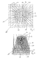
- FIG. 6 and 7 is the relationship between the individual surface lens portions 14 of the area lens assembly 9 and the detection area, more precisely detection area sections, shown in FIG Fig. 6 in a two-dimensional and in Fig. 7 in a three-dimensional representation, wherein for clarification of the relationships, the surface lens assembly 9 is shown oversized. In the illustration, the distance between the area lens assembly 9 and the detection plane is 2.80 m. As explained, is in the 6 and 7 First, the over-sized area lens assembly 9 shown, wherein the surface lens portions 14 are interconnected spider webs for clarity.
- view beams 16 lead to individual points (detection area sections) of the detection area.
- Fig. 1 is the detection area 18 with its square envelope contour and the parallel first Hüllkonturkanten 19 and the rectangular arranged second parallel Hüllkonturkanten 20 shown.
- these first and second Hüllkonturkanten 19, 20 as the first and second housing contour sections 21, 22 are again, in the embodiments shown on a plurality of housing sections.
- first parallel housing contour sections 21 and the second housing contour sections 22 arranged at right angles to the first housing contour sections 21 are formed by peripheral edges of the viewing section 5 of the housing, these peripheral edges being formed in the transitional area to a circumferential side wall 24 of the viewing section 5 and its front side 25.
- first and second housing contour sections 21, 22, which correspond to the first and second envelope contour edges 19, 20 of the detection region 18, are again in the form of an end contour impression 26 in the visible section 5. It is essential that the first and second housing contour sections 21, 22 extend parallel to the associated first and second envelope contour edges 19, 20 of the Detection area 18 are aligned.
- a housing contour in this case the peripheral contour of the housing, of the viewing section 5 at least approximately (except for the rounding of the corners) corresponds to the square envelope contour of the detection area 18 and is aligned therewith.
- first and second Hüll contour edges parallel first and second Gepurkonturabitese 21, 22 are also provided on the mounting portion namely, the first Gepurkonturabitese 21 and the second Gepurkonturabroughe 22 of side surfaces of the square rounded contoured insert portion 3 are formed.
- the housing peripheral contour of the insert portion 3 corresponds in the embodiment shown approximately (except for the rounded corners) of the envelope contour of the detection area 18 and is aligned to this by the corresponding sections of housing contour and envelope contour of the detection area 18 are aligned parallel to each other.
Landscapes
- Physics & Mathematics (AREA)
- General Physics & Mathematics (AREA)
- Spectroscopy & Molecular Physics (AREA)
- Photometry And Measurement Of Optical Pulse Characteristics (AREA)
- Geophysics And Detection Of Objects (AREA)
Abstract
Description
- Die Erfindung betrifft eine Einbau-Passiv-Infrarot-Sensorvorrichtung zum Einsatz als Bewegungs- und/oder Präsenzmelder gemäß Anspruch 1. Insbesondere betrifft die Erfindung eine Unterputz-PIR-Sensorvorrichtung.
- PIR-Sensorvorrichtungen als Bewegungsmelder und/oder als Präsenzmelder sind hinreichend bekannt. Diese im Regelfall als Aufputz-Sensorvorrichtungen ausgebildeten Geräte haben meist einen kreisrunden oder geometrisch nicht definierten Erfassungsbereich, wodurch es insbesondere in großen Räumen oder langgestreckten Fluren problematisch ist, den Raum möglichst lückenlos in unterschiedliche Erfassungsbereiche aufzuteilen, ohne dass sich die Erfassungsbereiche der zur Überwachung des Raumes bzw. Flures notwendigen Mehrzahl von Sensorvorrichtungen in großen Teilbereichen überschneiden. Hierdurch ist es schwierig eine definierte ortsabhängige Aktivierung unterschiedlicher Verbraucher zu realisieren.
- Ausgehend von diesem Stand der Technik liegt der Erfindung die Aufgabe zugrunde, eine verbesserte PIR-Sensorvorrichtung anzugeben, mittels derer große Flächen möglichst lückenlos überwachbar sind, wobei die Sensorvorrichtung vorzugsweise möglichst einfach montierbar bzw. ausrichtbar sein soll. Gleichzeitig soll die Sensorvorrichtung ästhetisch ansprechend, d.h. in einem vom Betrachter erfassbaren Bereich möglichst flach ausgestaltet sein.
- Diese Aufgabe wird mit einer Einbau-Passiv-Infrarot-Sensorvorrichtung, insbesondere einer Unterputz-PIR-Sensorvorrichtung, mit den Merkmalen des Anspruchs 1 gelöst. Vorteilhafte Weiterbildungen der Erfindung sind in den Unteransprüchen angegeben. In den Rahmen der Erfindung fallen sämtliche Kombinationen aus zumindest zwei von in der Beschreibung, den Ansprüchen und/oder den Figuren offenbarten Merkmalen.
- Der Erfindung liegt zunächst der Gedanke zugrunde, die mehrere Einzellinsen und/oder Linsenabschnitte aufweisende, noch weiter bevorzugt als Kunststoffspritzgussteil ausgebildete Flächenlinsenanordnung derart auszubilden bzw. zu berechnen, dass von dieser ein in einer, vorzugsweise in einer Parallelebene zur Flächenerstreckung der Flächenlinsenanordnung und mit Abstand zu dieser angeordneten, Erfassungsebene angeordneter Erfassungsbereich überwachbar ist, der eine Hüllkontur mit mindestens zwei zueinander parallelen Hüllkonturkanten aufweist. Bevorzugt ist die Flächenlinsenanordnung derart ausgebildet, dass dieser Erfassungsbereich eine Hüllkontur aufweist, insbesondere eine Waben- bzw. Sechseckkontur, eine Rechteckkontur oder besonders bevorzugt eine Quadratkontur, die es ermöglicht, eine große Fläche lückenlos in mehrere derartige Erfassungsbereiche zu unterteilen, ohne dass sich die Erfassungsbereiche überschneiden müssen, um zu gewährleisten, dass Bewegungen in definierten Bereichen definierte detektionspositionsabhängige Aktivierungen von durch die Sensorvorrichtung aktivierbaren Verbrauchern zur Folge hat.
- Damit nun ein Monteur eine Sensorvorrichtung mit einem derart beschaffenen Erfassungsbereich einfach montieren kann, ist weiterbildungsgemäß vorgesehen, dass sich die zwei parallelen ersten Hüllkonturkanten (im verkleinerten Maßstab) am Gehäuse als zwei parallele erste Gehäusekonturabschnitte, insbesondere Gehäuseumfangskonturabschnitte, wiederfinden, wobei diese zwei parallelen ersten, bevorzugt in einer gemeinsamen Querschnittsebene angeordneten Gehäusekonturabschnitte, die beispielsweise von zwei parallelen Gehäuseseitenflächen und/oder von zwei parallelen Gehäuseseitenkanten gebildet sind, parallel zu den ersten Hüllkonturkanten ausgerichtet sind, so dass die Lage der Erfassungsebene an der Gehäusekontur der Sensorvorrichtung ablesbar ist, so dass der Monteur durch Ausrichten des Gehäuses unmittelbar den Erfassungsbereich ausrichten und diese Ausrichtung an der Gehäuseausrichtung erkennen kann. Damit das weitere Aufgabenkriterium der Ausbildung einer ästhetisch ansprechenden Sensorvorrichtung erfüllt werden kann, ist vorgesehen, die Sensorvorrichtung als Einbau-Passiv-Infrarot-Sensorvorrichtung, insbesondere als Unterputz-PIR-Sensorvorrichtung, auszubilden, deren Gehäuse zumindest abschnittsweise, insbesondere größtenteils mit einem Einbauabschnitt in oder hinter einer Decken- oder Wandmontageöffnung, vorzugsweise aufweisend ein Standard-Durchmesser von 50 mm, versenkbar ist, so dass sichtbar auf der Decke oder Wand lediglich ein Sichtabschnitt verbleibt, der dann eine sehr geringe Höhenerstreckung aufweisen kann, so dass zumindest für den Betrachter der Eindruck entsteht, der gesamte Sensor habe eine extrem flache Ausgestaltung. Die mindestens eine, vorzugsweise ausschließlich eine PIR-Sensoreinheit, die mit Abstand zu der Flächenlinsenanordnung angeordnet werden muss, befindet sich vorzugsweise in dem versenkbaren Einbauabschnitt, so dass der notwendiger Weise zur Flächenlinsenanordnung einzuhaltende Brennweitenabstand die Höhenerstreckung des Sichtabschnittes, gemessen senkrecht zur Decke oder Wand, nicht negativ beeinflusst. Die Erfassungsebene, in welcher der Erfassungsbereich angeordnet ist, ist beabstandet von der Sensorvorrichtung, insbesondere über eine typische Raumhöhe aus einem Bereich zwischen 2 und 5 m, und parallel zu der Montagefläche (Decke oder Wand) und damit parallel zur Anlagefläche des Sichtabschnittes, mit welcher dieser an der Decke oder Wand anliegen kann, ausgerichtet.
- In Weiterbildung der Erfindung ist mit Vorteil vorgesehen, dass der Erfassungsbereich neben den ersten parallelen Hüllkonturkanten zweite, winklig, vorzugsweise rechtwinklig zu den ersten parallelen Hüllkonturkanten angeordnete parallele Hüllkonturkanten aufweist, die sich bevorzugt ebenfalls (in verkleinertem Maßstab) in der Gehäusekontur des Sensorgehäuses wiederfinden, wobei die korrespondierenden parallelen, bevorzugt in einer gemeinsamen Querschnittsebene angeordneten, zweiten Gehäusekonturabschnitte parallel zu den zweiten Hüllkonturkanten des Erfassungsbereichs ausgerichtet sind.
- Ganz besonders bevorzugt ist eine Ausführungsform, bei der die Gehäusekontur, insbesondere die Gehäuseumfangskontur zumindest eines Gehäuseabschnittes des Sensorgehäuses, insbesondere des Sichtabschnittes und/oder des Einbauabschnittes (im verkleinerten Maßstab), zumindest näherungsweise der Hüllkontur des Erfassungsbereich in der Erfassungsebene entspricht, wobei die Gehäuseumfangskontur zu der Hüllkontur des Erfassungsbereichs ausgerichtet ist, derart, dass die Orientierung der Hüllkontur des Erfassungsbereichs der Orientierung der Gehäuseumfangskontur entspricht. Anders ausgedrückt sind die einander entsprechenden (maßstäblich unterschiedlichen) Konturabschnitte von Gehäuse und Erfassungsbereich zueinander parallel ausgerichtet. Bevorzugt ist es dabei, wenn die Gehäuseumfangskontur, ebenso wie die Hüllkontur des Erfassungsbereichs, wabenförmig, rechteckig oder ganz besonders bevorzugt quadratisch ist, also derart, dass durch Aneinandersetzen unterschiedlicher (gleicher) Erfassungsbereiche eine große Fläche lückenlos abdeckbar ist, ohne dass sich dazu die Erfassungsbereiche überschneiden müssen, so dass wiederum definierte Aktivierungen unterschiedlicher, den Erfassungsbereichen zugeordneter Sensorvorrichtungen gewährleistet sind.
- Im Hinblick auf die Anordnung der ersten und/oder zweiten Gehäusekonturabschnitte, die sich vorzugsweise in einer gemeinsamen Querschnittsebene des Gehäuses befinden, gibt es verschiedene Möglichkeiten, wobei es besonders bevorzugt ist, wenn sich erste und zweite Gehäusekonturabschnitte (vorzugsweise in einer gemeinsamen Querschnittsebene) am Sichtabschnitt befinden, wobei zusätzlich oder alternativ auch eine Anordnung derartiger Gehäusekonturabschnitte am Einbauabschnitt möglich ist, wobei in diesem Fall nur bei der Montage die Ausrichtung des Erfassungsbereichs an der Gehäusekontur ablesbar ist, da der Einbauabschnitt im montierten Zustand in der Montageöffnung versenkt ist. Das Gleiche gilt auch für den Fall, dass die Gehäuseumfangskontur zumindest näherungsweise der Hüllkontur (Umfangshüllkontur) des Erfassungsbereichs entspricht. Der diese Umfangskontur aufweisende Gehäuseabschnitt kann am Einbauabschnitt und/oder am Sichtabschnitt vorgesehen werden, wobei die Anordnung am Sichtabschnitt bevorzugt ist.
- Die ersten und/oder zweiten parallelen Gehäusekonturabschnitte und/oder die Gehäuseumfangskontur können von Seitenflächenabschnitten des Sensorgehäuses gebildet sein. Bevorzugt ist die Bildung als Kantenabschnitte. Bevorzugt ist es, wenn die ersten und/oder zweiten Gehäusekonturabschnitte und/oder eine der Hüllkontur des Erfassungsbereichs entsprechende Gehäusekontur, insbesondere eine Gehäuseumfangskontur, von einer, vorzugsweise umfangsgeschlossenen, Kontureinformung und/oder einer vorzugsweise umfangsgeschlossenen Konturerhebung im Sichtabschnitt, insbesondere in einer Sichtabschnittsstirnseite, gebildet ist, wobei es besonders bevorzugt ist, wenn diese Kontureinformung und/oder Konturerhebung der Umfangskontur des Sichtabschnittes, zumindest näherungsweise, entspricht. Hierdurch können gleichzeitig ansprechende ästhetische Effekte erzielt werden.
- Ganz besonders bevorzugt ist es, wenn die Flächenlinsenanordnung im Sichtabschnitt angeordnet ist, wobei die Flächenlinsenanordnung bevorzugt die Querschnittsfläche des Einbauabschnittes seitlich, vorzugsweise auf allen Seiten, überragt. Die Anordnung der Flächenlinsenanordnung in dem eine größere Querschnittsfläche als der Einbauabschnitt aufweisenden Sichtabschnitt bietet viele Möglichkeiten in der Anpassung und Ausbildung der Flächenlinsenanordnung zur Erfassung eines im Verhältnis zum Einbauabschnittsquerschnitt vergleichsweise großen Erfassungsbereichs.
- Als besonders bevorzugt hat es sich herausgestellt, wenn der Verhältniswert zwischen der Flächenerstreckung des Sichtabschnittes und der parallel dazu angeordneten Querschnittsfläche des Einbauabschnittes zwischen 1,56 und 4,75 vorzugsweise zwischen 2,4 und 4,0, beträgt. Dabei wird unter der Flächenerstreckung des Sichtabschnittes die Flächenerstreckung der axialen Projektionsfläche des Sichtabschnittes verstanden. Ebenso ist es bevorzugt, wenn der Verhältniswert zwischen der Flächenerstreckung der Flächenlinsenanordnung und der parallel dazu angeordneten Querschnittsfläche des Einbauabschnittes zwischen 0,33 und 1,32, vorzugsweise zwischen 0,5 und 0,8, beträgt.
- Zur Erzielung eines optimalen ästhetischen Ergebnisses ist es besonders bevorzugt, wenn die Höhenerstreckung des Sichtabschnittes, gemessen senkrecht zur Anlagefläche, gering ist und noch weiter bevorzugt weniger als 7 mm, noch weiter bevorzugt weniger als 4 mm beträgt. Bevorzugt ist die Höhenerstreckung des Sichtabschnittes aus einem Wertebereich zwischen 2 und 4 mm, noch weiter bevorzugt zwischen 2,5 und 3,5 mm, gewählt.
- Ebenso ist es bevorzugt, wenn der Verhältniswert zwischen der Höhenerstreckung des Sichtabschnittes und der Gesamthöhe des Gehäuses der Sensorvorrichtung aus einem Wertebereich zwischen 1:10 und 1:30, vorzugsweise zwischen 1:15 und 1:25, gewählt ist.
- Optimale Ergebnisse hinsichtlich der Schaffung eines rechteckigen, vorzugsweise quadratischen Erfassungsbereichs können überraschend dadurch geschaffen werden, wenn die Flächenlinsenanordnung und/oder einzelne, vorzugsweise als Fresnel-Linsen ausgebildete, noch weiter bevorzugt asphärische Linsenabschnitte sechseckig, insbesondere bienenwabenförmig, konturiert sind.
- Die Erfindung führt auch auf ein Hausautomationssystem, umfassend mindestens eine erfindungsgemäße, als Bewegungs- und/oder Präsenzmelder ausgebildete Sensorvorrichtung und mindestens einen von dieser bei Detektierung einer Bewegung und/oder einer Präsenz einer Person aktivierbaren Verbraucher, insbesondere einer Leuchte. Ganz besonders bevorzugt umfasst das Hausautomationssystem mehrere derartige, vorzugsweise gleichartige Sensorvorrichtungen, die derart relativ zueinander und beabstandet zueinander angeordnet sind, dass deren Erfassungsbereiche lückenlos, vorzugsweise ohne oder nur mit geringer Überschneidung eine große Bodenfläche abdecken.
- Weitere Vorteile, Merkmale und Einzelheiten der Erfindung ergeben sich aus der nachfolgenden Beschreibung bevorzugter Ausführungsbeispiele sowie anhand der Zeichnungen.
- Diese zeigen in:
- Fig. 1:
- eine perspektivische Ansicht eines Ausführungsbeispiels eines Einbau-PIR-Sensors von schräg hinten,
- Fig. 2:
- eine perspektivische Ansicht des Sensors gemäß
Fig. 1 von schräg vorne, - Fig. 3:
- eine teilgeschnittene perspektivische Ansicht des Sensors gemäß
Fig. 1 und 2 von schräg vorne, - Fig. 4:
- eine teilgeschnittene Ansicht des Sensors gemäß den
Fig. 1 bis 3 von schräg hinten, - Fig. 5:
- eine Draufsicht auf ein Kunststoffspritzgussteil mit mehrere Fresnel-Linsenabschnitte aufweisenden Flächenlinsenanordnung,
- Fig. 6/7:
- Diagramme, aus denen die Zuordnung von Erfassungsbereichsabschnitten zu Flächenlinsenabschnitten der Flächenlinsenanordnung ersichtlich ist.
- In den Figuren sind gleiche Elemente und Elemente mit der gleichen Funktion mit den gleichen Bezugszeichen gekennzeichnet.
- In den
Fig. 1 bis 4 ist eine als Bewegungsmelder ausgebildete Einbau-Passiv-Infrarot-Sensorvorrichtung in Form einer Unterputz-PIR-Sensorvorrichtung gezeigt. Die Sensorvorrichtung 1 umfasst ein Gehäuse 2 aus Kunststoffspritzgussteilen. Das Gehäuse 2 ist unterteilt in einen hinteren, langgestreckten Einsatzabschnitt zum Durchstecken durch eine Montageöffnung, beispielsweise in einer abgehängten Decke. Seitlich an dem Einsatzabschnitt befinden sich auf zwei voneinander abgewandten Seiten zwei Federbügel 4, die im montierten Zustand einen außerhalb der Montageöffnung befindlichen Sichtabschnitt 5 des Gehäuses 2 mit einer hinteren Anlagefläche 6 plan gegen die Wand oder die Decke verspannen, wobei sich die Federbügel 4 beispielsweise an der Rückseite der abgehängten Decke abstützen. In einem hinteren stirnseitigen Bereich des Einsatzabschnittes 3 befindet sich eine Anschlussbuchse 7, hier ausgebildet zur Integration in ein KNX-Hausbussystem, wobei über die Anschlussbuchse 7 die Spannungsversorgung der Sensorelektronik erfolgt und auch ein Sensorsignal ausgeleitet werden kann. Alternativ kann der Sensor auch unmittelbar als Schalteinrichtung mit Leistungselektronik ausgebildet werden, um einen Verbraucher in Abhängigkeit der Detektion der Bewegung einer Person ein- oder auszuschalten. - Der Sichtabschnitt 5 ist im Verhältnis zum langgestreckten Einbauabschnitt 3 sehr flach ausgebildet und weist eine geringe Höhenerstreckung h, gemessen senkrecht zur Flächenerstreckung der Anlagefläche 6, auf. Die Höhenerstreckung h beträgt im Ausführungsbeispiel 1,74 mm. Die Höhenerstreckung des gesamten Gehäuses 2 entspricht der Summe aus der Höhenerstreckung h des Einsatzabschnittes und der gleichgerichteten Höhenerstreckung des Einbauabschnittes 3. Die Höhenerstreckung I des Gehäuses beträgt im gezeigten Ausführungsbeispiel 20,78 mm.
- Wie sich aus den
Fig. 1 bis 4 ergibt, überragt der Sichtabschnitt 5 die Querschnittsfläche des Einsatzabschnittes 3 allseitig. In dem gezeigten Ausführungsbeispiel beträgt die Flächenerstreckung (axiale Projektionsfläche) des Sichtabschnittes 5 4.703 mm2 und die Flächenerstreckung der Querschnittsfläche des Einsatzabschnittes beträgt 1.474 mm2. - Wie sich insbesondere aus den Schnittdarstellungen gemäß den
Fig. 3 und 4 ergibt, ist das Gehäuse 2 mehrteilig ausgebildet und umfasst den einteiligen Einsatzabschnitt 3 sowie den mehrteiligen Sichtabschnitt 5. - Dieser wiederum umfasst ein flaches, zentriert angeordnetes Kunststoffspritzgussteil 8 aus infrarottransparentem Kunststoff, beispielsweise Polyethylen, wobei in dieses Kunststoffspritzgussteil 8, wie sich insbesondere aus
Fig. 4 andeutungsweise ergibt, eine Flächenlinsenanordnung 9 eingeformt ist. Umgeben ist das Kunststoffspritzgussteil 8 von einem Rahmenabschnittsteil 10, welches mit dem Kunststoffspritzgussteil und dem Einsatzabschnitt 3 verrastet ist. Das Rahmenabschnittsteil 10 fixiert somit das Kunststoffspritzgussteil 8 am Einsatzteil 3. - Mit Abstand zu und hinter der Flächenlinsenanordnung 9 befindet sich die eigentliche Sensorelektronik 11. Diese umfasst einen auf einer Leiterplatte 12 angeordneten PIR-Sensor 13, auf den die Sichtstrahlen eines Erfassungsbereichs fokussiert werden.
- In
Fig. 5 ist das die Flächenlinsenanordnung 9 aufweisende Kunststoffspritzgussteil 8 derFig. 1 bis 4 im Detail gezeigt. Zu erkennen ist die in dem gezeigten Ausführungsbeispiel einundneunzig sechseckige Flächenlinsenabschnitte 14 aufweisende Flächenlinsenanordnung 9, welche ebenfalls eine sechseckige, hier wabenförmige Hüllkontur aufweist. Die Flächenlinsenabschnitte 14 sind als asphärische Fresnel-Linsenabschnitte ausgebildet und derart beschaffen, dass mit diesen, wie im Folgenden erläutert werden wird, ein quadratischer Erfassungsbereich in einer Erfassungsebene überwachbar ist. - In den
Fig. 6 und 7 ist der Zusammenhang zwischen den einzelnen Flächenlinsenabschnitten 14 der Flächenlinsenanordnung 9 und dem Erfassungsbereich, genauer von Erfassungsbereichsabschnitten, dargestellt, und zwar inFig. 6 in einer zweidimensionalen und inFig. 7 in einer dreidimensionalen Darstellung, wobei zur Verdeutlichung der Zusammenhänge die Flächenlinsenanordnung 9 übergroß dargestellt ist. In der Darstellung beträgt der Abstand zwischen der Flächenlinsenanordnung 9 und der Erfassungsebene 2,80 m. Wie erläutert, ist in denFig. 6 und 7 zunächst die übergroß dargestellte Flächenlinsenanordnung 9 gezeigt, wobei die Flächenlinsenabschnitte 14 zur besseren Verdeutlichung spinnennetzartig miteinander verbunden sind. - In den Darstellungen führen von der parallel zur Flächenlinsenanordnung 9 angeordneten Erfassungsebene 15 Sichtstrahlen 16 zu einzelnen Punkten (Erfassungsbereichsabschnitten) des Erfassungsbereichs. Dies ist eine vereinfachte Darstellung, da von jedem Erfassungsbereichsabschnitt 17 zwei Sichtstrahlenbündel zu den zugehörigen Flächenlinsenabschnitten führen, die diese auf jeweils eine Detektorfläche des PIR-Sensors in an sich bekannter Weise zur Differenzsignalbildung lenkt.
- Zu erkennen ist in den
Fig. 6 und 7 die quadratische Hüllkontur (umhüllende) des Erfassungsbereichs 18. Dieser besteht in dem gezeigten Ausführungsbeispiel aus zwei parallelen ersten Hüllkonturkanten 19 und zwei rechtwinklig dazu angeordneten parallelen zweiten Hüllkonturkanten 20, die sich in dem gezeigten Ausführungsbeispiel zu einem Quadrat ergänzen. - In
Fig. 1 ist der Erfassungsbereich 18 mit seiner quadratischen Hüllkontur und den parallelen ersten Hüllkonturkanten 19 und den dazu rechtwinklig angeordneten zweiten parallelen Hüllkonturkanten 20 dargestellt. An dem in denFig. 1 und 2 dargestellten Gehäuse 2 finden sich diese ersten und zweiten Hüllkonturkanten 19, 20 als erste und zweite Gehäusekonturabschnitte 21, 22 wieder, und zwar in dem gezeigten Ausführungsbeispielen an mehreren Gehäuseabschnitten. - So werden die ersten parallelen Gehäusekonturabschnitte 21 und die zweiten, hier rechtwinklig zu den ersten Gehäusekonturabschnitten 21 angeordneten Gehäusekonturabschnitte 22 von Umfangskanten des Sichtabschnittes 5 des Gehäuses gebildet, wobei diese Umfangskanten im Übergangsbereich zu einer Umfangsseitenwand 24 des Sichtabschnittes 5 und dessen Stirnseite 25 gebildet sind. Ferner finden sich erste und zweite Gehäusekonturabschnitte 21, 22, die mit den ersten und zweiten Hüllkonturkanten 19, 20 des Erfassungsbereichs 18 korrespondieren, wieder als stirnseitige Kontureinformung 26 im Sichtabschnitt 5. Wesentlich dabei ist, dass die ersten und zweiten Gehäusekonturabschnitte 21, 22 parallel zu den zugehörigen ersten und zweiten Hüllkonturkanten 19, 20 des Erfassungsbereichs 18 ausgerichtet sind. In dem gezeigten Ausführungsbeispiel ist zudem realisiert, dass eine Gehäusekontur, hier die Gehäuseumfangskontur, des Sichtabschnittes 5 zumindest näherungsweise (bis auf die Abrundung der Ecken) der quadratischen Hüllkontur des Erfassungsbereichs 18 entspricht und zu dieser ausgerichtet ist.
- Aus
Fig. 1 ist zu erkennen, dass zu den ersten und zweiten Hüllkonturkanten korrespondierende parallele erste und zweite Gehäusekonturabschnitte 21, 22 auch am Einbauabschnitt vorgesehen sind und zwar werden die ersten Gehäusekonturabschnitte 21 und die zweiten Gehäusekonturabschnitte 22 von Seitenflächen des bis auf abgerundete Ecken quadratisch konturierten Einsatzabschnittes 3 gebildet. Auch die Gehäuseumfangskontur des Einsatzabschnittes 3 entspricht in dem gezeigten Ausführungsbeispiel näherungsweise (bis auf die gerundeten Ecken) der Hüllkontur des Erfassungsbereichs 18 und ist zu diesem ausgerichtet, indem die korrespondierenden Abschnitte von Gehäusekontur und Hüllkontur des Erfassungsbereichs 18 zueinander parallel ausgerichtet sind. -
- 1
- Sensorvorrichtung
- 2
- Gehäuse
- 3
- Einsatzabschnitt
- 4
- Federbügel
- 5
- Sichtabschnitt
- 6
- Anlagefläche
- 7
- Anschlussbuchse
- 8
- Kunststoffspritzgussteil
- 9
- Flächenlinsenanordnung
- 10
- Rahmenabschnitt
- 11
- Sensorelektronik
- 12
- Leiterplatte
- 13
- PIR-Sensor
- 14
- Flächenlinsenabschnitte
- 15
- Erfassungsebene
- 16
- Sichtstrahlen
- 17
- Erfassungsbereichsabschnitt
- 18
- Erfassungsbereich
- 19
- erste Hüllkonturkanten
- 20
- zweite Hüllkonturkanten
- 21
- erste Gehäusekonturabschnitte
- 22
- zweite Gehäusekonturabschnitte
- 24
- Umfangsseitenwand
- 25
- Stirnseite
- 26
- Kontureinformung
Claims (12)
- Einbau-Passiv-Infrarot-Sensorvorrichtung, insbesondere Unterputz-PIR-Sensorvorrichtung, mit mindestens einer in einem Gehäuse (2) angeordneten PIR-Sensoreinheit und mit einer mit Abstand zu der PIR-Sensoreinheit angeordneten Flächenlinsenanordnung (9), die derart ausgebildet ist, dass die Sensorvorrichtung (1) in einer Erfassungsebene (15) einen Erfassungsbereich (18) mit einer zwei parallele erste Hüllkonturkanten (19) aufweisenden Hüllkontur aufweist.
- Sensorvorrichtung nach Anspruch 1,
dadurch gekennzeichnet,
dass das Gehäuse (2) einen in einer Montageöffnung versenkbaren Einbauabschnitt und einen eine Anlagefläche (6) zur äußeren Anlage an einen die Montageöffnung umgebenden Wand- oder Deckenabschnitt anbietenden Sichtabschnitt (5) aufweist, wobei das Gehäuse (2) zwei parallele erste Gehäusekonturabschnitte (21), insbesondere Gehäuseseitenflächen oder Gehäuseseitenkanten, aufweist, die parallel zu den parallelen ersten Hüllkonturkanten (19) der Hüllkontur des Erfassungsbereichs (18) ausgerichtet sind. - Sensorvorrichtung nach einem der Ansprüche 1 oder 2,
dadurch gekennzeichnet,
dass die Hüllkontur des Erfassungsbereich (18) in einer Erfassungsebene (15) zwei parallele zweite Hüllkanten aufweist, die winklig, insbesondere rechtwinklig zu den parallelen ersten Hüllkanten angeordnet sind. - Sensorvorrichtung nach einem der vorhergehenden Ansprüche,
dadurch gekennzeichnet,
dass das Gehäuse (2) zwei parallele zweite Gehäusekonturabschnitte (22), insbesondere Gehäuseseitenflächen oder Gehäuseseitenkanten, aufweist, die parallel zu den parallelen zweiten Hüllkonturkanten (20) der Hüllkontur des Erfassungsbereichs (18) ausgerichtet sind. - Sensorvorrichtung nach einem der vorhergehenden Ansprüche,
dadurch gekennzeichnet,
dass die Hüllkontur des Erfassungsbereichs (18) in der Erfassungsebene (15) rechtwinklig, insbesondere quadratisch ist. - Sensorvorrichtung nach einem der vorhergehenden Ansprüche,
dadurch gekennzeichnet,
dass die Gehäuseumfangskontur eines Gehäuseabschnitts, insbesondere des Sichtabschnitts (5) und/oder des Einbauabschnitts, im verkleinerten Maßstab, zumindest näherungsweise, der, bevorzugt rechtwinkligen, noch weiter bevorzugt quadratischen, Hüllkontur des Erfassungsbereichs in der Erfassungsebene (15) entspricht und die einander entsprechenden Konturabschnitte von Gehäuseabschnitt und Erfassungsbereich (18) zueinander parallel ausgerichtet sind. - Sensorvorrichtung nach einem der vorhergehenden Ansprüche,
dadurch gekennzeichnet,
dass die ersten und/oder die zweiten Gehäusekonturabschnitte (21, 22) am Einbauabschnitt und/oder am Sichtabschnitt (5) vorgesehen sind. - Sensorvorrichtung nach einem der vorhergehenden Ansprüche,
dadurch gekennzeichnet,
dass, insbesondere stirnseitig, in dem Sichtabschnitt (5) eine Kontureinformung (26) und/oder eine Konturerhebung vorgesehen sind/ist, die die ersten und/oder zweiten Gehäusekonturabschnitte (21, 22) bilden/bildet und/oder die den Gehäusekonturabschnitt bilden/bildet, der im verkleinerten Maßstab, zumindest näherungsweise, der Hüllkontur des Erfassungsbereichs in der Erfassungsebene (15) entspricht. - Sensorvorrichtung nach einem der vorhergehenden Ansprüche,
dadurch gekennzeichnet,
dass die Flächenlinsenanordnung (9) im Sichtabschnitt (5) angeordnet ist und vorzugsweise die Querschnittsfläche des Einbauabschnitts, bevorzugt allseitig, seitlich überragt. - Sensorvorrichtung nach einem der vorhergehenden Ansprüche,
dadurch gekennzeichnet,
dass der Verhältniswert zwischen der Flächenerstreckung des Sichtabschnittes (5) und der parallel dazu angeordneten Querschnittsfläche des Einbauabschnittes zwischen 1,56 und 4,75, vorzugsweise zwischen 2,4 und 4,0 beträgt. - Sensorvorrichtung nach einem der vorhergehenden Ansprüche,
dadurch gekennzeichnet,
dass die Höhenerstreckung des Sichtabschnittes (5) senkrecht zur Anlagefläche (6) weniger als 7 mm, bevorzugt weniger als 4 mm, vorzugsweise zwischen 2 und 4 mm, noch weiter bevorzugt zwischen 2,5 und 3,5 mm beträgt. - Sensorvorrichtung nach einem der vorhergehenden Ansprüche,
dadurch gekennzeichnet,
dass der Verhältniswert zwischen der Höhenerstreckung des Sichtabschnittes (5) und der Gesamthöhe des Gehäuses (2) der Sensorvorrichtung (1) aus einem Wertebereich zwischen 1:10 und 1:30, vorzugsweise zwischen 1:15 und 1:25 gewählt ist.
Applications Claiming Priority (1)
| Application Number | Priority Date | Filing Date | Title |
|---|---|---|---|
| DE202012101356U DE202012101356U1 (de) | 2012-04-13 | 2012-04-13 | Einbau-Passiv-Infrarot-Sensorvorrichtung |
Publications (3)
| Publication Number | Publication Date |
|---|---|
| EP2650849A2 true EP2650849A2 (de) | 2013-10-16 |
| EP2650849A3 EP2650849A3 (de) | 2018-01-03 |
| EP2650849B1 EP2650849B1 (de) | 2021-07-07 |
Family
ID=47632889
Family Applications (1)
| Application Number | Title | Priority Date | Filing Date |
|---|---|---|---|
| EP13153551.0A Active EP2650849B1 (de) | 2012-04-13 | 2013-01-31 | Einbau-Passiv-Infrarot-Sensorvorrichtung |
Country Status (2)
| Country | Link |
|---|---|
| EP (1) | EP2650849B1 (de) |
| DE (1) | DE202012101356U1 (de) |
Cited By (2)
| Publication number | Priority date | Publication date | Assignee | Title |
|---|---|---|---|---|
| CN106461456A (zh) * | 2014-02-28 | 2017-02-22 | Abb股份公司 | 红外运动检测器 |
| FR3080435A1 (fr) * | 2018-04-23 | 2019-10-25 | B L M Distribution (Base Logistique Marchande Et De Distribution) | Boite d'encastrement pour plafond |
Families Citing this family (2)
| Publication number | Priority date | Publication date | Assignee | Title |
|---|---|---|---|---|
| DE102016116363A1 (de) | 2016-09-01 | 2018-03-01 | Abb Ag | Installationsgerät für die Deckenmontage |
| DE102016116364A1 (de) | 2016-09-01 | 2018-03-01 | Abb Ag | Installationsgerät für die Deckenmontage |
Family Cites Families (2)
| Publication number | Priority date | Publication date | Assignee | Title |
|---|---|---|---|---|
| DE10134565A1 (de) * | 2001-07-16 | 2003-02-06 | Luxmate Controls Gmbh Dornbirn | Bewegungssensor |
| EP2259238A1 (de) * | 2009-06-03 | 2010-12-08 | Theben HTS AG | Vorrichtung zum Feststellen einer von einem Lebewesen ausgehenden IR-Strahlung |
-
2012
- 2012-04-13 DE DE202012101356U patent/DE202012101356U1/de not_active Expired - Lifetime
-
2013
- 2013-01-31 EP EP13153551.0A patent/EP2650849B1/de active Active
Non-Patent Citations (1)
| Title |
|---|
| None |
Cited By (3)
| Publication number | Priority date | Publication date | Assignee | Title |
|---|---|---|---|---|
| CN106461456A (zh) * | 2014-02-28 | 2017-02-22 | Abb股份公司 | 红外运动检测器 |
| CN106461456B (zh) * | 2014-02-28 | 2019-01-22 | Abb股份公司 | 红外运动检测器 |
| FR3080435A1 (fr) * | 2018-04-23 | 2019-10-25 | B L M Distribution (Base Logistique Marchande Et De Distribution) | Boite d'encastrement pour plafond |
Also Published As
| Publication number | Publication date |
|---|---|
| EP2650849B1 (de) | 2021-07-07 |
| DE202012101356U1 (de) | 2013-07-16 |
| EP2650849A3 (de) | 2018-01-03 |
Similar Documents
| Publication | Publication Date | Title |
|---|---|---|
| DE102013014164B4 (de) | Struktur für einen Ultraschallsensor | |
| EP2650849B1 (de) | Einbau-Passiv-Infrarot-Sensorvorrichtung | |
| EP2860126A1 (de) | Vorrichtung zur Aufnahme und zum Halten von Gegenständen und zugehöriger Verbindungskörper | |
| DE202020100373U1 (de) | Set aus einem Leiteranschlusselement und einem Befestigungselement | |
| DE202011107600U1 (de) | Steckverbinder für ein Möbel | |
| DE102014011078B3 (de) | Klemmscheibenpaar, Sensorbefestigungsanordnung und Montageverfahren zum Aufbau derselben | |
| DE202005003051U1 (de) | Optoelektronische Sensoreinrichtung | |
| DE202013104227U1 (de) | Elektrischer Samowar | |
| WO2015128114A1 (de) | Infrarot-bewegungsmelder | |
| DE102013002852A1 (de) | Verteilerbox | |
| DE102016104084A1 (de) | Leuchtensystem | |
| DE102006059547B4 (de) | Lichtschrankenanordnung | |
| EP1282092B1 (de) | Raumsensor mit Montageadapter | |
| DE3346699A1 (de) | Bewegungsmelder | |
| DE202009001069U1 (de) | Sensor zur Ermittlung der Temperatur im Innenraum eines Kraftfahrzeugs, Klimabedienteil für eine Kfz-Klimanlage und Vorrichtung zur Ermittlung der Temperatur in einem Kfz | |
| DE102014205819B4 (de) | System zur Aufnahme von Lichtmodulen sowie Verfahren für dessen Herstellung | |
| EP4220240A1 (de) | Optischer sensor | |
| DE9201889U1 (de) | Bewegungsmelder | |
| AT513684B1 (de) | Beckenkonstruktion für eine Fischwanderhilfe in Kombination mit einem Wasserwirbelkraftwerk | |
| DE102007050561A1 (de) | Gehäuse | |
| DE10301879B3 (de) | Steckvorrichtungselement mit Montagegewinde | |
| CH698033B1 (de) | Gehäuse mit einem die Gehäuseöffnung abdeckenden Frontrahmen. | |
| DE8536429U1 (de) | Linsensystem für die Optik eines Infrarot-Detektors | |
| DE202013012653U1 (de) | Elektrisches/elektronisches Installationsgerät mit Passiv-Infrarot-Bewegungsmelder | |
| DE102015203007B4 (de) | Befestigungsvorrichtung für ein Lichtgittergehäuse |
Legal Events
| Date | Code | Title | Description |
|---|---|---|---|
| PUAI | Public reference made under article 153(3) epc to a published international application that has entered the european phase |
Free format text: ORIGINAL CODE: 0009012 |
|
| AK | Designated contracting states |
Kind code of ref document: A2 Designated state(s): AL AT BE BG CH CY CZ DE DK EE ES FI FR GB GR HR HU IE IS IT LI LT LU LV MC MK MT NL NO PL PT RO RS SE SI SK SM TR |
|
| AX | Request for extension of the european patent |
Extension state: BA ME |
|
| PUAL | Search report despatched |
Free format text: ORIGINAL CODE: 0009013 |
|
| AK | Designated contracting states |
Kind code of ref document: A3 Designated state(s): AL AT BE BG CH CY CZ DE DK EE ES FI FR GB GR HR HU IE IS IT LI LT LU LV MC MK MT NL NO PL PT RO RS SE SI SK SM TR |
|
| AX | Request for extension of the european patent |
Extension state: BA ME |
|
| RIC1 | Information provided on ipc code assigned before grant |
Ipc: H02G 3/12 20060101ALI20171128BHEP Ipc: G01J 5/00 20060101ALI20171128BHEP Ipc: G01J 5/02 20060101ALI20171128BHEP Ipc: G01J 5/04 20060101ALI20171128BHEP Ipc: G01J 5/08 20060101ALI20171128BHEP Ipc: G08B 13/19 20060101AFI20171128BHEP Ipc: H02G 3/20 20060101ALI20171128BHEP |
|
| STAA | Information on the status of an ep patent application or granted ep patent |
Free format text: STATUS: REQUEST FOR EXAMINATION WAS MADE |
|
| 17P | Request for examination filed |
Effective date: 20180703 |
|
| RBV | Designated contracting states (corrected) |
Designated state(s): AL AT BE BG CH CY CZ DE DK EE ES FI FR GB GR HR HU IE IS IT LI LT LU LV MC MK MT NL NO PL PT RO RS SE SI SK SM TR |
|
| STAA | Information on the status of an ep patent application or granted ep patent |
Free format text: STATUS: EXAMINATION IS IN PROGRESS |
|
| 17Q | First examination report despatched |
Effective date: 20190225 |
|
| GRAP | Despatch of communication of intention to grant a patent |
Free format text: ORIGINAL CODE: EPIDOSNIGR1 |
|
| STAA | Information on the status of an ep patent application or granted ep patent |
Free format text: STATUS: GRANT OF PATENT IS INTENDED |
|
| INTG | Intention to grant announced |
Effective date: 20210205 |
|
| GRAS | Grant fee paid |
Free format text: ORIGINAL CODE: EPIDOSNIGR3 |
|
| GRAA | (expected) grant |
Free format text: ORIGINAL CODE: 0009210 |
|
| STAA | Information on the status of an ep patent application or granted ep patent |
Free format text: STATUS: THE PATENT HAS BEEN GRANTED |
|
| AK | Designated contracting states |
Kind code of ref document: B1 Designated state(s): AL AT BE BG CH CY CZ DE DK EE ES FI FR GB GR HR HU IE IS IT LI LT LU LV MC MK MT NL NO PL PT RO RS SE SI SK SM TR |
|
| REG | Reference to a national code |
Ref country code: GB Ref legal event code: FG4D Free format text: NOT ENGLISH |
|
| REG | Reference to a national code |
Ref country code: AT Ref legal event code: REF Ref document number: 1409342 Country of ref document: AT Kind code of ref document: T Effective date: 20210715 |
|
| REG | Reference to a national code |
Ref country code: DE Ref legal event code: R096 Ref document number: 502013015812 Country of ref document: DE |
|
| REG | Reference to a national code |
Ref country code: IE Ref legal event code: FG4D Free format text: LANGUAGE OF EP DOCUMENT: GERMAN |
|
| REG | Reference to a national code |
Ref country code: LT Ref legal event code: MG9D |
|
| REG | Reference to a national code |
Ref country code: NL Ref legal event code: MP Effective date: 20210707 |
|
| PG25 | Lapsed in a contracting state [announced via postgrant information from national office to epo] |
Ref country code: NO Free format text: LAPSE BECAUSE OF FAILURE TO SUBMIT A TRANSLATION OF THE DESCRIPTION OR TO PAY THE FEE WITHIN THE PRESCRIBED TIME-LIMIT Effective date: 20211007 Ref country code: RS Free format text: LAPSE BECAUSE OF FAILURE TO SUBMIT A TRANSLATION OF THE DESCRIPTION OR TO PAY THE FEE WITHIN THE PRESCRIBED TIME-LIMIT Effective date: 20210707 Ref country code: PT Free format text: LAPSE BECAUSE OF FAILURE TO SUBMIT A TRANSLATION OF THE DESCRIPTION OR TO PAY THE FEE WITHIN THE PRESCRIBED TIME-LIMIT Effective date: 20211108 Ref country code: NL Free format text: LAPSE BECAUSE OF FAILURE TO SUBMIT A TRANSLATION OF THE DESCRIPTION OR TO PAY THE FEE WITHIN THE PRESCRIBED TIME-LIMIT Effective date: 20210707 Ref country code: FI Free format text: LAPSE BECAUSE OF FAILURE TO SUBMIT A TRANSLATION OF THE DESCRIPTION OR TO PAY THE FEE WITHIN THE PRESCRIBED TIME-LIMIT Effective date: 20210707 Ref country code: ES Free format text: LAPSE BECAUSE OF FAILURE TO SUBMIT A TRANSLATION OF THE DESCRIPTION OR TO PAY THE FEE WITHIN THE PRESCRIBED TIME-LIMIT Effective date: 20210707 Ref country code: BG Free format text: LAPSE BECAUSE OF FAILURE TO SUBMIT A TRANSLATION OF THE DESCRIPTION OR TO PAY THE FEE WITHIN THE PRESCRIBED TIME-LIMIT Effective date: 20211007 Ref country code: LT Free format text: LAPSE BECAUSE OF FAILURE TO SUBMIT A TRANSLATION OF THE DESCRIPTION OR TO PAY THE FEE WITHIN THE PRESCRIBED TIME-LIMIT Effective date: 20210707 Ref country code: HR Free format text: LAPSE BECAUSE OF FAILURE TO SUBMIT A TRANSLATION OF THE DESCRIPTION OR TO PAY THE FEE WITHIN THE PRESCRIBED TIME-LIMIT Effective date: 20210707 Ref country code: SE Free format text: LAPSE BECAUSE OF FAILURE TO SUBMIT A TRANSLATION OF THE DESCRIPTION OR TO PAY THE FEE WITHIN THE PRESCRIBED TIME-LIMIT Effective date: 20210707 |
|
| PG25 | Lapsed in a contracting state [announced via postgrant information from national office to epo] |
Ref country code: PL Free format text: LAPSE BECAUSE OF FAILURE TO SUBMIT A TRANSLATION OF THE DESCRIPTION OR TO PAY THE FEE WITHIN THE PRESCRIBED TIME-LIMIT Effective date: 20210707 Ref country code: LV Free format text: LAPSE BECAUSE OF FAILURE TO SUBMIT A TRANSLATION OF THE DESCRIPTION OR TO PAY THE FEE WITHIN THE PRESCRIBED TIME-LIMIT Effective date: 20210707 Ref country code: GR Free format text: LAPSE BECAUSE OF FAILURE TO SUBMIT A TRANSLATION OF THE DESCRIPTION OR TO PAY THE FEE WITHIN THE PRESCRIBED TIME-LIMIT Effective date: 20211008 |
|
| REG | Reference to a national code |
Ref country code: DE Ref legal event code: R097 Ref document number: 502013015812 Country of ref document: DE |
|
| PG25 | Lapsed in a contracting state [announced via postgrant information from national office to epo] |
Ref country code: DK Free format text: LAPSE BECAUSE OF FAILURE TO SUBMIT A TRANSLATION OF THE DESCRIPTION OR TO PAY THE FEE WITHIN THE PRESCRIBED TIME-LIMIT Effective date: 20210707 |
|
| PLBE | No opposition filed within time limit |
Free format text: ORIGINAL CODE: 0009261 |
|
| STAA | Information on the status of an ep patent application or granted ep patent |
Free format text: STATUS: NO OPPOSITION FILED WITHIN TIME LIMIT |
|
| PG25 | Lapsed in a contracting state [announced via postgrant information from national office to epo] |
Ref country code: SM Free format text: LAPSE BECAUSE OF FAILURE TO SUBMIT A TRANSLATION OF THE DESCRIPTION OR TO PAY THE FEE WITHIN THE PRESCRIBED TIME-LIMIT Effective date: 20210707 Ref country code: SK Free format text: LAPSE BECAUSE OF FAILURE TO SUBMIT A TRANSLATION OF THE DESCRIPTION OR TO PAY THE FEE WITHIN THE PRESCRIBED TIME-LIMIT Effective date: 20210707 Ref country code: RO Free format text: LAPSE BECAUSE OF FAILURE TO SUBMIT A TRANSLATION OF THE DESCRIPTION OR TO PAY THE FEE WITHIN THE PRESCRIBED TIME-LIMIT Effective date: 20210707 Ref country code: EE Free format text: LAPSE BECAUSE OF FAILURE TO SUBMIT A TRANSLATION OF THE DESCRIPTION OR TO PAY THE FEE WITHIN THE PRESCRIBED TIME-LIMIT Effective date: 20210707 Ref country code: CZ Free format text: LAPSE BECAUSE OF FAILURE TO SUBMIT A TRANSLATION OF THE DESCRIPTION OR TO PAY THE FEE WITHIN THE PRESCRIBED TIME-LIMIT Effective date: 20210707 Ref country code: AL Free format text: LAPSE BECAUSE OF FAILURE TO SUBMIT A TRANSLATION OF THE DESCRIPTION OR TO PAY THE FEE WITHIN THE PRESCRIBED TIME-LIMIT Effective date: 20210707 |
|
| 26N | No opposition filed |
Effective date: 20220408 |
|
| PG25 | Lapsed in a contracting state [announced via postgrant information from national office to epo] |
Ref country code: IT Free format text: LAPSE BECAUSE OF FAILURE TO SUBMIT A TRANSLATION OF THE DESCRIPTION OR TO PAY THE FEE WITHIN THE PRESCRIBED TIME-LIMIT Effective date: 20210707 |
|
| PG25 | Lapsed in a contracting state [announced via postgrant information from national office to epo] |
Ref country code: MC Free format text: LAPSE BECAUSE OF FAILURE TO SUBMIT A TRANSLATION OF THE DESCRIPTION OR TO PAY THE FEE WITHIN THE PRESCRIBED TIME-LIMIT Effective date: 20210707 |
|
| REG | Reference to a national code |
Ref country code: CH Ref legal event code: PL |
|
| REG | Reference to a national code |
Ref country code: BE Ref legal event code: MM Effective date: 20220131 |
|
| PG25 | Lapsed in a contracting state [announced via postgrant information from national office to epo] |
Ref country code: LU Free format text: LAPSE BECAUSE OF NON-PAYMENT OF DUE FEES Effective date: 20220131 |
|
| PG25 | Lapsed in a contracting state [announced via postgrant information from national office to epo] |
Ref country code: BE Free format text: LAPSE BECAUSE OF NON-PAYMENT OF DUE FEES Effective date: 20220131 |
|
| PG25 | Lapsed in a contracting state [announced via postgrant information from national office to epo] |
Ref country code: LI Free format text: LAPSE BECAUSE OF NON-PAYMENT OF DUE FEES Effective date: 20220131 Ref country code: CH Free format text: LAPSE BECAUSE OF NON-PAYMENT OF DUE FEES Effective date: 20220131 |
|
| PG25 | Lapsed in a contracting state [announced via postgrant information from national office to epo] |
Ref country code: IE Free format text: LAPSE BECAUSE OF NON-PAYMENT OF DUE FEES Effective date: 20220131 |
|
| REG | Reference to a national code |
Ref country code: AT Ref legal event code: MM01 Ref document number: 1409342 Country of ref document: AT Kind code of ref document: T Effective date: 20220131 |
|
| PG25 | Lapsed in a contracting state [announced via postgrant information from national office to epo] |
Ref country code: AT Free format text: LAPSE BECAUSE OF NON-PAYMENT OF DUE FEES Effective date: 20220131 |
|
| P01 | Opt-out of the competence of the unified patent court (upc) registered |
Effective date: 20230512 |
|
| PG25 | Lapsed in a contracting state [announced via postgrant information from national office to epo] |
Ref country code: HU Free format text: LAPSE BECAUSE OF FAILURE TO SUBMIT A TRANSLATION OF THE DESCRIPTION OR TO PAY THE FEE WITHIN THE PRESCRIBED TIME-LIMIT; INVALID AB INITIO Effective date: 20130131 |
|
| PG25 | Lapsed in a contracting state [announced via postgrant information from national office to epo] |
Ref country code: MK Free format text: LAPSE BECAUSE OF FAILURE TO SUBMIT A TRANSLATION OF THE DESCRIPTION OR TO PAY THE FEE WITHIN THE PRESCRIBED TIME-LIMIT Effective date: 20210707 Ref country code: CY Free format text: LAPSE BECAUSE OF FAILURE TO SUBMIT A TRANSLATION OF THE DESCRIPTION OR TO PAY THE FEE WITHIN THE PRESCRIBED TIME-LIMIT Effective date: 20210707 |
|
| REG | Reference to a national code |
Ref country code: DE Ref legal event code: R082 Ref document number: 502013015812 Country of ref document: DE Representative=s name: MATHYS & SQUIRE EUROPE PATENTANWAELTE PARTNERS, DE |
|
| PG25 | Lapsed in a contracting state [announced via postgrant information from national office to epo] |
Ref country code: MT Free format text: LAPSE BECAUSE OF FAILURE TO SUBMIT A TRANSLATION OF THE DESCRIPTION OR TO PAY THE FEE WITHIN THE PRESCRIBED TIME-LIMIT Effective date: 20210707 |
|
| PG25 | Lapsed in a contracting state [announced via postgrant information from national office to epo] |
Ref country code: TR Free format text: LAPSE BECAUSE OF FAILURE TO SUBMIT A TRANSLATION OF THE DESCRIPTION OR TO PAY THE FEE WITHIN THE PRESCRIBED TIME-LIMIT Effective date: 20210707 |
|
| PGFP | Annual fee paid to national office [announced via postgrant information from national office to epo] |
Ref country code: GB Payment date: 20260121 Year of fee payment: 14 |
|
| PGFP | Annual fee paid to national office [announced via postgrant information from national office to epo] |
Ref country code: DE Payment date: 20260119 Year of fee payment: 14 |
|
| PGFP | Annual fee paid to national office [announced via postgrant information from national office to epo] |
Ref country code: FR Payment date: 20260128 Year of fee payment: 14 |