EP2650501A1 - Sheet metal turbine housing - Google Patents
Sheet metal turbine housing Download PDFInfo
- Publication number
- EP2650501A1 EP2650501A1 EP11847246.3A EP11847246A EP2650501A1 EP 2650501 A1 EP2650501 A1 EP 2650501A1 EP 11847246 A EP11847246 A EP 11847246A EP 2650501 A1 EP2650501 A1 EP 2650501A1
- Authority
- EP
- European Patent Office
- Prior art keywords
- turbine
- sheet metal
- scroll part
- scroll
- housing
- Prior art date
- Legal status (The legal status is an assumption and is not a legal conclusion. Google has not performed a legal analysis and makes no representation as to the accuracy of the status listed.)
- Granted
Links
Images


Classifications
-
- F—MECHANICAL ENGINEERING; LIGHTING; HEATING; WEAPONS; BLASTING
- F01—MACHINES OR ENGINES IN GENERAL; ENGINE PLANTS IN GENERAL; STEAM ENGINES
- F01D—NON-POSITIVE DISPLACEMENT MACHINES OR ENGINES, e.g. STEAM TURBINES
- F01D25/00—Component parts, details, or accessories, not provided for in, or of interest apart from, other groups
- F01D25/24—Casings; Casing parts, e.g. diaphragms, casing fastenings
-
- F—MECHANICAL ENGINEERING; LIGHTING; HEATING; WEAPONS; BLASTING
- F01—MACHINES OR ENGINES IN GENERAL; ENGINE PLANTS IN GENERAL; STEAM ENGINES
- F01D—NON-POSITIVE DISPLACEMENT MACHINES OR ENGINES, e.g. STEAM TURBINES
- F01D9/00—Stators
- F01D9/02—Nozzles; Nozzle boxes; Stator blades; Guide conduits, e.g. individual nozzles
- F01D9/026—Scrolls for radial machines or engines
-
- F—MECHANICAL ENGINEERING; LIGHTING; HEATING; WEAPONS; BLASTING
- F02—COMBUSTION ENGINES; HOT-GAS OR COMBUSTION-PRODUCT ENGINE PLANTS
- F02B—INTERNAL-COMBUSTION PISTON ENGINES; COMBUSTION ENGINES IN GENERAL
- F02B37/00—Engines characterised by provision of pumps driven at least for part of the time by exhaust
- F02B37/02—Gas passages between engine outlet and pump drive, e.g. reservoirs
-
- F—MECHANICAL ENGINEERING; LIGHTING; HEATING; WEAPONS; BLASTING
- F02—COMBUSTION ENGINES; HOT-GAS OR COMBUSTION-PRODUCT ENGINE PLANTS
- F02B—INTERNAL-COMBUSTION PISTON ENGINES; COMBUSTION ENGINES IN GENERAL
- F02B39/00—Component parts, details, or accessories relating to, driven charging or scavenging pumps, not provided for in groups F02B33/00 - F02B37/00
-
- F—MECHANICAL ENGINEERING; LIGHTING; HEATING; WEAPONS; BLASTING
- F05—INDEXING SCHEMES RELATING TO ENGINES OR PUMPS IN VARIOUS SUBCLASSES OF CLASSES F01-F04
- F05D—INDEXING SCHEME FOR ASPECTS RELATING TO NON-POSITIVE-DISPLACEMENT MACHINES OR ENGINES, GAS-TURBINES OR JET-PROPULSION PLANTS
- F05D2220/00—Application
- F05D2220/40—Application in turbochargers
-
- F—MECHANICAL ENGINEERING; LIGHTING; HEATING; WEAPONS; BLASTING
- F05—INDEXING SCHEMES RELATING TO ENGINES OR PUMPS IN VARIOUS SUBCLASSES OF CLASSES F01-F04
- F05D—INDEXING SCHEME FOR ASPECTS RELATING TO NON-POSITIVE-DISPLACEMENT MACHINES OR ENGINES, GAS-TURBINES OR JET-PROPULSION PLANTS
- F05D2230/00—Manufacture
- F05D2230/20—Manufacture essentially without removing material
- F05D2230/23—Manufacture essentially without removing material by permanently joining parts together
- F05D2230/232—Manufacture essentially without removing material by permanently joining parts together by welding
-
- F—MECHANICAL ENGINEERING; LIGHTING; HEATING; WEAPONS; BLASTING
- F05—INDEXING SCHEMES RELATING TO ENGINES OR PUMPS IN VARIOUS SUBCLASSES OF CLASSES F01-F04
- F05D—INDEXING SCHEME FOR ASPECTS RELATING TO NON-POSITIVE-DISPLACEMENT MACHINES OR ENGINES, GAS-TURBINES OR JET-PROPULSION PLANTS
- F05D2230/00—Manufacture
- F05D2230/50—Building or constructing in particular ways
- F05D2230/54—Building or constructing in particular ways by sheet metal manufacturing
-
- Y—GENERAL TAGGING OF NEW TECHNOLOGICAL DEVELOPMENTS; GENERAL TAGGING OF CROSS-SECTIONAL TECHNOLOGIES SPANNING OVER SEVERAL SECTIONS OF THE IPC; TECHNICAL SUBJECTS COVERED BY FORMER USPC CROSS-REFERENCE ART COLLECTIONS [XRACs] AND DIGESTS
- Y02—TECHNOLOGIES OR APPLICATIONS FOR MITIGATION OR ADAPTATION AGAINST CLIMATE CHANGE
- Y02T—CLIMATE CHANGE MITIGATION TECHNOLOGIES RELATED TO TRANSPORTATION
- Y02T50/00—Aeronautics or air transport
- Y02T50/60—Efficient propulsion technologies, e.g. for aircraft
Definitions
- the present invention relates to a sheet metal turbine housing employed in a turbocharger that sends compressed air to the engine by using the energy of exhaust gas from the engine, and more particularly to the surrounding structure of a center core part of the turbine housing.
- a conventional turbine housing 001 includes, as shown in FIG. 9 , a scroll part 002, a core part 003 surrounding the outer circumference of a turbine wheel 004, and an outlet part 005 leading to an exhaust gas flow passage, these being formed integrally by casting.
- the turbine housing is thick in various parts and has high heat capacity, because of which, when disposed upstream of an exhaust gas purification catalyst, the housing impedes the warming of the catalyst.
- it is important to reduce the heat capacity of the housing by making it from sheet metal so that it is thinner and lighter, so as to improve the purification performance of the catalyst by speeding up the warming and activation of the catalyst.
- a turbine housing made of sheet metal requires a coupling portion for coupling a part on the side of a bearing housing in which a bearing that supports a rotating shaft of the turbine blade is fitted and a part on the side of the outlet leading to the exhaust gas flow passage.
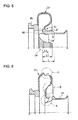
- FIG. 10 shows a conventional technique regarding this coupling portion described in Patent Document 1 (Japanese Patent Application Laid-open No. 2008-106667 ).
- a coupling ring 08 having a plurality of circumferentially arranged columnar coupling portions 081 is disclosed, as shown in FIG. 10 .
- a flange 03 on the bearing housing side, a flange 05 on the nozzle wall surface, and the coupling ring 08 are fabricated as separate components.
- the coupling ring 08 and the flange 05 on the nozzle wall surface are welded together all around (W6), and the coupling ring 08 and the flange 03 on the bearing housing side are welded together all around (W7).
- the cost is increased because of the increased number of components.
- an ample clearance needs to be formed between the housing portion and the turbine, in consideration of the amount of thermal strain that accompanies the welding of the entire circumference. A large clearance is problematic because it lowers the driving performance of the turbine, and results in poorer turbocharger performance.
- the turbine housing can be made more lightweight by making it from sheet metal, a sheet metal housing will likely have lower strength. Therefore, the turbine housing needs a structure that provides impact resistance so that, in the event of a burst following an excessively high-speed rotation of the turbine rotor under some circumstances, fractured pieces will not fly off.
- Patent Document 1 Japanese Patent Application Laid-open No. 2008-106667
- Objects of the invention are to prevent changes in tip clearance caused by thermal deformation of the scroll main body, to reduce weight and cost of the turbine housing, and to improve durability and reliability of the turbine and impact resistance of the turbine housing, by forming a center core part that is disposed at the center of a scroll part of a turbocharger in one piece from a steel pipe member to include a flow passage outlet part, a bearing receiving portion, and supports.
- the present invention resides in a sheet metal turbine housing mounted downstream of an engine exhaust manifold and having a scroll part made by a sheet metal scroll member to form a spiral exhaust gas passage of a turbocharger that drives a turbine by using exhaust gas
- the sheet metal turbine housing including: a center core part disposed in a central part of the scroll part and including a housing portion at one end surrounding the turbine, a bearing receiving portion at the other end in which a bearing axially supporting the turbine is fitted, and a plurality of circumferentially spaced supports bridging a gap between the housing portion and the bearing receiving portion in an axial direction of the turbine; the housing portion, the bearing receiving portion, and the supports being formed in one piece from a steel pipe member in an annular shape.
- the center core is formed in one piece from a steel pipe member in an annular shape.
- Such a structure allows for a reduction in material thickness and thermal capacity of the turbine part so that it can heat up quickly to promote the warming of an exhaust gas purification system, and thus enables efficient purification processing by the exhaust gas purification system.
- the steel pipe turbocharger can be produced at lower cost than the conventional center core.
- the center core is formed in one piece from a steel pipe member to include parts corresponding to the flange on the bearing housing side, the nozzle wall surface, and the coupling ring, there is no need to take account of thermal strain that accompanies the process of welding together separate components, and the clearance between the housing portion and the turbine can be made smaller. Thereby, a reduction in the turbine driving performance caused by a large tip clearance can be avoided.
- the center core part is a one-piece article made from a steel pipe member, it can have higher strength than a cast structure with a complex shape, and can have higher impact resistance as it is made of steel pipe.
- the supports may have a cross-sectional shape, as viewed from the axial direction of the turbine, with acute-angled corners both upstream and downstream of a flow of exhaust gas so that the supports have an upstream side face and a downstream side face inclined along the flow of gas.
- the supports have side faces that extend along the flow of exhaust gas, the supports cause less flow resistance in the gas passage and so the rotation efficiency of the turbine blade can be improved.
- the supports have a cross-sectional area that is necessary to secure sufficient rigidity and strength to couple a part on the bearing housing side and a part on the flow passage outlet side surrounding the turbine blade and to maintain the clearance between them and the turbine blade constant.
- the scroll part may have a first sheet metal scroll part fixedly attached to the housing portion at the one end and a second sheet metal scroll part fixedly attached to the bearing receiving portion at the other end, and the first scroll part and the second scroll part may be joined together by penetration butt welding at an outer circumferential portion of the scroll part.
- the housing portion surrounding the turbine may have a larger sheet thickness in a portion facing an outer circumference of the turbine than in other portions.
- the turbine housing With the housing portion having a larger sheet thickness in a portion facing the outer circumference of the turbine than in other portions, the turbine housing will have better impact resistance in the event of a burst following an excessively high-speed rotation of the turbine rotor, as the housing portion will suffer minimum damage from flying fractured pieces.
- the portion having the larger sheet thickness should preferably be at least a portion facing an outer circumference of a turbine wheel of the turbine.
- the portion facing at least the outer circumference of the turbine wheel of the turbine has an increased sheet thickness, i.e., the portion on the outer side of the turbine wheel is made thicker, which allows for efficient prevention of damage to the housing portion caused by flying fractured pieces, because the fragments of the wheel will fly outward in the event of a burst following an excessively high-speed rotation of the turbine rotor.
- the sheet metal scroll member of the scroll part should preferably have a double wall structure.
- the scroll part has better impact resistance, so that, in the event of a burst caused by an excessively high-speed rotation of the turbine rotor, fractured pieces are reliably prevented from flying off to the outside through the scroll member.
- the double structure also enables the functions of withstanding thermal stress from the internal gas and of preventing a gas leak to be served separately by the inner wall and the outer wall, whereby, a reduction in weight as well as attendant improvement in vibration resistance can be achieved, which further improves the impact resistance of the turbine housing.
- the center core is made from a steel pipe member processed into an annular shape, whereby the material thickness is reduced and so is the thermal capacity, which provides the effects of speeding up the temperature rise of the turbine part, and promoting the warming of the exhaust gas purification system, thereby enabling efficient purification processing by the system.
- the turbocharger is more lightweight.
- the steel pipe member can be produced at lower cost than conventional cast products.
- the sheet metal turbine housing 1 is roughly made up of a scroll part 3, a center core part 9, and an outlet pipe part 23, the scroll part 3 being formed by a first scroll part 5 and a second scroll part 7 butted opposite each other and welded together.
- the turbine housing 1 is formed by joining these four parts by welding.
- the scroll part 3 that forms a spiral gas passage is formed by butting two parts, the first scroll part 5 and the second scroll part 7, and joining them along the butted portion all around by penetration butt welding.
- the sheet metal parts are welded together not by one-side fillet welding but by penetration butt welding wherein the ends of the sheet metal parts are butted against each other and welded (part a).
- the first scroll part 5 and the second scroll part 7 may be thin sheet metal parts made of heat resistant steel such as austenitic stainless steel or the like and formed in respective shapes.
- the penetration butt-welded portion (a) runs along the outer circumference of the scroll part 3, at an intermediate position thereof in the axial direction of the turbine wheel 24. Therefore, the scroll parts each have a sectional shape corresponding to that of the gas passage generally half split in the scroll direction.
- the weld joint structure of the outer circumferential part of the scroll part 3 is formed by penetration butt welding which is advantageous in withstanding tensile stress, so that the weld joint has higher durability and reliability.
- a lap joint welded along the edge on one side by fillet welding as in a conventional structure may be less durable and reliable when the pressure of the exhaust gas is applied orthogonally to the outer circumferential wall surface of the scroll part 3, as the pressure acts to bend the welded ends, whereby a force may act to peel the welded edge of the overlapped sheet metal parts and stress concentration may occur.
- the center core part 9 which is generally cylindrical as a whole, and includes a bearing receiving portion 91 at the other end in which a bearing for supporting a rotating shaft 25 of the turbine wheel 24 (see FIG. 3 ) is fitted, a housing portion 93 formed at one end such as to surround the outer circumference of the turbine wheel 24 and to form a gas discharge port, and a plurality of circumferentially spaced supports 92 bridging a gap between the bearing receiving portion 15 and the housing portion 93, these all being formed integrally.
- the center core part 9 can be formed easily by machining with a multiple axis tool.
- a center core part 9 similar to that of the first embodiment may be fabricated also from a solid bar material cut into a steel pipe shape.
- the center core part 9 As the center core part 9 is produced by a machining process, it is finished with close dimensional tolerance, and therefore the clearance d ( FIG. 3 ) between the center core part and the outer circumference of the turbine wheel 24 can be reduced, which will reduce the amount of exhaust gas leaking through the clearance d and improve the power for driving the compressor wheel (not shown) coaxially coupled to the turbine wheel 24, i.e., the overall performance of the turbocharger will be improved.
- the center core part 9 is a steel pipe member and has high material strength, it can have smaller thicknesses in various parts and thus is more lightweight.
- the center core part 9 having various parts made thinner has a lower heat capacity, and therefore heats up quickly by the exhaust gas.
- the center core part 9 can thereby prevent a drop in the temperature of exhaust gas soon after the engine is started, to promote the warming of the catalyst in the exhaust gas purification system disposed downstream of the exhaust gas system, allowing for effective and speedy purification of gas.
- the center core part 9 is formed in one piece from a steel pipe member by machining, no additional welding work is necessary. Also, a considerable cost reduction is possible by automatic control of the multiple axis tool in the machining process.
- the plurality of circumferentially spaced supports 92 are provided to the center core part 9 on the outer side of the turbine wheel 24 so as to secure flow passages 94 for the gas in the scroll part 3 to flow smoothly in the spiral direction toward the center, as well as to connect the bearing receiving portion 91 and the housing portion 93.
- FIG. 4 illustrates the cross-sectional shape of the plurality of circumferentially arranged supports 92 as viewed from the axial direction of the turbine wheel 24.
- the supports 92 are formed by removing material of the generally cylindrical center core part 9 (see FIG. 2 ) having the bearing receiving portion 15 and a flow passage outlet part 17 by machining, e.g., cutting, between portions that will be the supports 92 so that the flow passages 94 are formed therebetween.
- the support 92 includes a flat surface on a side face 95 upstream of the exhaust gas flow and a flat surface on a downstream side face 96, with an upstream inclination angle ⁇ 1 (acute angle) and a downstream inclination angle ⁇ 2 (acute angle) in a cross section as viewed from the axial direction of the turbine wheel 24.
- the upstream inclination angle ⁇ 1 may be about 20°
- the downstream inclination angle ⁇ 2 may be about 70°.
- ⁇ 1 is less than 20°, then the cross-sectional shape of the support will be too flat, and, in order to secure a cross-sectional area that can provide necessary strength, the cross-sectional area of the flow passages 94 between the supports 92 will have to be made smaller. If ⁇ 1 is more than 70°, a reduction in the projected area of the support 92 as seen from the flow direction will not be possible, because of which the effect of reducing the gas flow loss caused by the supports 92 and of reducing generation of wakes (fluid distortion) cannot be achieved.
- the acute angle range is therefore preferably from 20° to 70°. The above applies not only to the upstream inclination angle ⁇ 1, but also to the downstream inclination angle ⁇ 2.
- the support 92 has a generally rectangular upstream side face 95 and downstream side face 96
- the material between the portions that will form the supports 92 can be readily removed by a cutting process, i.e., the supports 92 can be formed or fabricated easily by machining.
- the support 92 is formed to have a generally rectangular cross-sectional shape, with the upstream corner having the angle ⁇ 1 and the downstream corner having the angle ⁇ 2 so that the upstream side face 95 and the downstream side face 96 are inclined along the flow of gas.
- the flow resistance of the exhaust gas passage is therefore lower than that with the conventional rectangular cross-sectional design, and thus the gas flow loss caused by the supports 92 and generation of wakes (fluid distortion) can be reduced.
- the supports 92 connecting the bearing receiving portion 91 and the housing portion 93 also have strength and heat resistance sufficient for maintaining the clearance between the turbine wheel 24 and the inner circumferential surface of the center core part 9 constant even under high temperatures or external forces.
- To the distal end of the housing portion 93 is joined the tubular outlet pipe part 23 that is welded thereto all around.
- the first scroll part 5 is welded all around to the outer circumference of the joint between the housing portion 93 and the supports 92 (weld joint b), which is at one end of the center core part 9.
- the second scroll part 7 is welded all around to the outer circumference of the joint between the bearing receiving portion 91 and the supports 92 (weld joint c), which is at the other end of the center core part 9.
- the scroll part 3 and the center core part 9 are made into one piece.
- the bearing receiving portion 91, the housing portion 93, and the supports 92 connecting these are integrally formed, i.e., the bearing receiving portion 91, housing portion 93, and supports 92 are formed in one piece by a cutting process.
- While the supports 92 in FIG. 4 are circumferentially generally equally arranged, they may be arranged irregularly depending on the scroll shape or other factors, to achieve desired turbocharger performance.
- the center core part 33 which is generally cylindrical as a whole, and includes a bearing receiving portion 35 in which a bearing for supporting the rotating shaft of the turbine wheel 24 is fitted, a housing portion 37 that surrounds the outer circumference of the turbine wheel 24 to form a gas discharge port, and a plurality of circumferentially spaced supports 92 bridging a gap between the bearing receiving portion 35 and the housing portion 37, these all being formed in one piece.
- This center core part 33 is made of the same material and produced by the same method as that of the first embodiment described in the foregoing.
- the configuration of the second embodiment shown in FIG. 5 does not include the outlet pipe part 23 of the first embodiment, it goes without saying that there may be the outlet pipe part 23 further connected to the distal end of the housing 37 in FIG. 5 .
- the characteristic feature of the second embodiment, as shown in FIG. 5 is that the housing portion 37 has its sheet thickness varying in the axial direction and includes a thick portion X.
- the length L of this thick portion X is defined by a length from one end on the side of the exhaust gas passage where the supports 92 are formed.
- the other end of the thick portion X should preferably extend to a length that includes the length L1 of the turbine 39 inside the housing portion 37 to its axial end, or at least the length L2 of the turbine wheel 24 part to its axial end, in order to achieve effective impact resistance of the turbine housing without too much increase in weight that accompanies the increase in sheet thickness.
- the next stage is energy absorption through fracture of a part B on the radially inner side of the scroll part 31.
- the part B absorbs about 25% of the kinetic energy.
- This is followed by further energy absorption through fracture of a part C of the scroll part 31.
- the part C absorbs about 5% of the kinetic energy.
- FIG. 7 shows the changes with time in kinetic energy absorbed through fracture of the parts A, B, and C as the fragments of the turbine wheel 24 hit the respective parts.
- the results were obtained through analysis.
- the thick portion X of the housing portion 37 absorbs about 70% of the energy
- the part B on the radially inner side of the scroll part 31 absorbs about 25% of the energy
- the part C in the main part of the scroll part 31 absorbs about 5% of the energy, so that there remains no energy at the end and thus the fragments are prevented from flying off to the outside.
- the thickness and length of the thick portion X of the housing portion 37 therefore need to be designed so that the thick portion X will be capable of absorbing about 70% or more of the kinetic energy of the turbine wheel 24.
- the axial length needs to contain at least the axial length L2 of the turbine wheel 24, preferably the axial length L1 of the turbine part 39, in consideration of the traveling direction of fragments of the turbine wheel 24.
- the thickness and others of the turbine housing are designed so as to ensure its impact resistance, such that all the kinetic energy of the turbine wheel 24, in the event of a burst following an excessively high-speed rotation of the wheel, will be absorbed by the housing portion 37 and the scroll part 31, whereby fragments of the turbine wheel 24 are prevented from flying off to the outside of the housing portion 37.
- the thick portion X is provided at least in a portion facing the outer circumference of the turbine wheel 24, i.e., the sheet thickness is increased only on the outer side of the wheel. In the event of a burst following an excessively high-speed rotation of the turbine wheel 24, the fragments will travel outwards from the turbine wheel 24. Therefore, increasing the sheet thickness in a portion that is most likely be subjected to damage can provide efficient containment of the fragments.
- the third embodiment is characterized in that the sheet metal scroll member of the scroll part 41 has a double wall structure, unlike the structure in the second embodiment As shown in FIG. 8 , the scroll part 41 is formed by an inner wall 43 and an outer wall 45, the inner wall 43 serving a function of withstanding thermal stress from the internal gas, and the outer wall 45 serving a function of preventing a gas leak. An air layer K is present between the inner wall 43 and the outer wall 45 to form an insulation layer.
- the part C can absorb more energy through fracture, and the amount of energy absorbed by the part C is about 25% in the third embodiment, as compared to the scroll part 31 having a single wall structure in the second embodiment.
- the thick portion X need only have a sheet thickness and a length to be able to absorb about 60% or more of the energy.
- the sheet material of the scroll part 41 has a double structure so that the scroll part 41 has better impact resistance, whereby the fragments of the turbine wheel 24 are reliably prevented from flying off to the outside through the scroll part 41 during a burst following an excessively high-speed rotation of the wheel.
- the double structure enables the functions of withstanding the thermal stress from the internal gas and preventing a gas leak to be separately served by the inner wall 43 and the outer wall 45, so that a scroll part capable of both reducing thermal stress and preventing a leak can be obtained. This leads to a reduction in weight and better turbocharger performance, and better impact resistance of the turbine housing.
- the bearing receiving portion, the flow passage outlet part, and the supports of the center core part that is disposed at the center of the scroll part are formed in one piece from a steel pipe member, so that the invention is suitably applied to a turbine housing structure, for minimizing a drop in the exhaust gas temperature, for preventing changes in tip clearance caused by thermal deformation of the scroll main body, for reducing weight and cost, and for improving durability, reliability, and impact resistance.
Landscapes
- Engineering & Computer Science (AREA)
- Mechanical Engineering (AREA)
- General Engineering & Computer Science (AREA)
- Supercharger (AREA)
Abstract
Description
- The present invention relates to a sheet metal turbine housing employed in a turbocharger that sends compressed air to the engine by using the energy of exhaust gas from the engine, and more particularly to the surrounding structure of a center core part of the turbine housing.
- A
conventional turbine housing 001 includes, as shown inFIG. 9 , ascroll part 002, acore part 003 surrounding the outer circumference of aturbine wheel 004, and anoutlet part 005 leading to an exhaust gas flow passage, these being formed integrally by casting. As it is made by casting, the turbine housing is thick in various parts and has high heat capacity, because of which, when disposed upstream of an exhaust gas purification catalyst, the housing impedes the warming of the catalyst. In view of more stringent exhaust gas regulations in recent years, it is important to reduce the heat capacity of the housing by making it from sheet metal so that it is thinner and lighter, so as to improve the purification performance of the catalyst by speeding up the warming and activation of the catalyst. - Since sheet metal parts are thin and less strong, a turbine housing made of sheet metal requires a coupling portion for coupling a part on the side of a bearing housing in which a bearing that supports a rotating shaft of the turbine blade is fitted and a part on the side of the outlet leading to the exhaust gas flow passage.
-
FIG. 10 shows a conventional technique regarding this coupling portion described in Patent Document 1 (Japanese Patent Application Laid-open No.2008-106667
Acoupling ring 08 having a plurality of circumferentially arrangedcolumnar coupling portions 081 is disclosed, as shown inFIG. 10 . Aflange 03 on the bearing housing side, aflange 05 on the nozzle wall surface, and thecoupling ring 08 are fabricated as separate components. Thecoupling ring 08 and theflange 05 on the nozzle wall surface are welded together all around (W6), and thecoupling ring 08 and theflange 03 on the bearing housing side are welded together all around (W7). - As the
flange 03 on the bearing housing side, theflange 05 on the nozzle wall surface, and thecoupling ring 08 are fabricated as separate components and welded together all around, the cost is increased because of the increased number of components. Moreover, an ample clearance needs to be formed between the housing portion and the turbine, in consideration of the amount of thermal strain that accompanies the welding of the entire circumference. A large clearance is problematic because it lowers the driving performance of the turbine, and results in poorer turbocharger performance. - Another problem is that, while the turbine housing can be made more lightweight by making it from sheet metal, a sheet metal housing will likely have lower strength. Therefore, the turbine housing needs a structure that provides impact resistance so that, in the event of a burst following an excessively high-speed rotation of the turbine rotor under some circumstances, fractured pieces will not fly off.
- Patent Document 1: Japanese Patent Application Laid-open No.
2008-106667 - The present invention was made in view of these problems. Objects of the invention are to prevent changes in tip clearance caused by thermal deformation of the scroll main body, to reduce weight and cost of the turbine housing, and to improve durability and reliability of the turbine and impact resistance of the turbine housing, by forming a center core part that is disposed at the center of a scroll part of a turbocharger in one piece from a steel pipe member to include a flow passage outlet part, a bearing receiving portion, and supports.
- To achieve the above object, the present invention resides in a sheet metal turbine housing mounted downstream of an engine exhaust manifold and having a scroll part made by a sheet metal scroll member to form a spiral exhaust gas passage of a turbocharger that drives a turbine by using exhaust gas, the sheet metal turbine housing including: a center core part disposed in a central part of the scroll part and including a housing portion at one end surrounding the turbine, a bearing receiving portion at the other end in which a bearing axially supporting the turbine is fitted, and a plurality of circumferentially spaced supports bridging a gap between the housing portion and the bearing receiving portion in an axial direction of the turbine; the housing portion, the bearing receiving portion, and the supports being formed in one piece from a steel pipe member in an annular shape.
- As compared to the conventional center core formed by the flange on the bearing housing side, the flange on the nozzle wall surface, and the coupling ring fabricated separately and welded together, the center core is formed in one piece from a steel pipe member in an annular shape. Such a structure allows for a reduction in material thickness and thermal capacity of the turbine part so that it can heat up quickly to promote the warming of an exhaust gas purification system, and thus enables efficient purification processing by the exhaust gas purification system.
Aside from being made more lightweight, the steel pipe turbocharger can be produced at lower cost than the conventional center core. - As the center core is formed in one piece from a steel pipe member to include parts corresponding to the flange on the bearing housing side, the nozzle wall surface, and the coupling ring, there is no need to take account of thermal strain that accompanies the process of welding together separate components, and the clearance between the housing portion and the turbine can be made smaller. Thereby, a reduction in the turbine driving performance caused by a large tip clearance can be avoided.
As the center core part is a one-piece article made from a steel pipe member, it can have higher strength than a cast structure with a complex shape, and can have higher impact resistance as it is made of steel pipe. - In the present invention, preferably, the supports may have a cross-sectional shape, as viewed from the axial direction of the turbine, with acute-angled corners both upstream and downstream of a flow of exhaust gas so that the supports have an upstream side face and a downstream side face inclined along the flow of gas.
- Exhaust gas flows spirally through the scroll part toward the center into the turbine part. With the structure described above, as the supports have side faces that extend along the flow of exhaust gas, the supports cause less flow resistance in the gas passage and so the rotation efficiency of the turbine blade can be improved.
The supports have a cross-sectional area that is necessary to secure sufficient rigidity and strength to couple a part on the bearing housing side and a part on the flow passage outlet side surrounding the turbine blade and to maintain the clearance between them and the turbine blade constant. - In the present invention, preferably, the scroll part may have a first sheet metal scroll part fixedly attached to the housing portion at the one end and a second sheet metal scroll part fixedly attached to the bearing receiving portion at the other end, and the first scroll part and the second scroll part may be joined together by penetration butt welding at an outer circumferential portion of the scroll part.
- Since the scroll part is subjected to tensile stress and bending force by the pulsed exhaust gas flows, such a structure adopting penetration butted welding that is advantageous in withstanding the bending force can provide the effects of improving the durability and reliability of the turbine housing due to its increased strength, and of making the welding work easier because the weld joint is along the outer circumference of the scroll part.
- In the present invention, preferably, the housing portion surrounding the turbine may have a larger sheet thickness in a portion facing an outer circumference of the turbine than in other portions.
- With the housing portion having a larger sheet thickness in a portion facing the outer circumference of the turbine than in other portions, the turbine housing will have better impact resistance in the event of a burst following an excessively high-speed rotation of the turbine rotor, as the housing portion will suffer minimum damage from flying fractured pieces.
- The portion having the larger sheet thickness should preferably be at least a portion facing an outer circumference of a turbine wheel of the turbine.
- The portion facing at least the outer circumference of the turbine wheel of the turbine has an increased sheet thickness, i.e., the portion on the outer side of the turbine wheel is made thicker, which allows for efficient prevention of damage to the housing portion caused by flying fractured pieces, because the fragments of the wheel will fly outward in the event of a burst following an excessively high-speed rotation of the turbine rotor.
- In the present invention, the sheet metal scroll member of the scroll part should preferably have a double wall structure. With the sheet material of the scroll part having a double structure, the scroll part has better impact resistance, so that, in the event of a burst caused by an excessively high-speed rotation of the turbine rotor, fractured pieces are reliably prevented from flying off to the outside through the scroll member.
The double structure also enables the functions of withstanding thermal stress from the internal gas and of preventing a gas leak to be served separately by the inner wall and the outer wall, whereby, a reduction in weight as well as attendant improvement in vibration resistance can be achieved, which further improves the impact resistance of the turbine housing. - The center core is made from a steel pipe member processed into an annular shape, whereby the material thickness is reduced and so is the thermal capacity, which provides the effects of speeding up the temperature rise of the turbine part, and promoting the warming of the exhaust gas purification system, thereby enabling efficient purification processing by the system.
As the material thickness is reduced, the turbocharger is more lightweight. Also, the steel pipe member can be produced at lower cost than conventional cast products. -
-
FIG. 1 is a perspective view illustrating the schematic structure of the turbine housing according to a first embodiment of the present invention; -
FIG. 2 shows a cross section of essential parts along A-A ofFIG. 1 ; -
FIG. 3 shows a cross section of essential parts along B-B ofFIG. 1 , with a turbine wheel assembled therein; -
FIG. 4 is a cross-sectional diagram for explaining the part with supports; -
FIG. 5 is a cross-sectional view of essential parts illustrating a second embodiment and corresponding toFIG. 3 ; -
FIG. 6 illustrates a failure mode wherein fractured pieces fly off through the scroll member to the outside; -
FIG. 7 shows changes with time of kinetic energy of the turbine wheel; -
FIG. 8 is a cross-sectional view of essential parts illustrating a third embodiment and corresponding toFIG. 3 ; -
FIG. 9 is a diagram for explaining a conventional technique in which the housing portion is made by casting; and -
FIG. 10 is a schematic configuration diagram of major parts of a conventional sheet metal turbine housing. - The illustrated embodiments of the present invention will be hereinafter described in detail. It should be noted that, unless otherwise particularly specified, the sizes, materials, shapes, and relative arrangement or the like of constituent components described in these embodiments are not intended to limit the scope of this invention.
- The turbine housing according to the first embodiment of the present invention will be described with reference to
FIG. 1 to FIG. 4 .
As shown inFIG. 1 and FIG. 2 , the sheetmetal turbine housing 1 is roughly made up of ascroll part 3, acenter core part 9, and anoutlet pipe part 23, thescroll part 3 being formed by afirst scroll part 5 and asecond scroll part 7 butted opposite each other and welded together. Theturbine housing 1 is formed by joining these four parts by welding. - The
scroll part 3 that forms a spiral gas passage is formed by butting two parts, the first scrollpart 5 and thesecond scroll part 7, and joining them along the butted portion all around by penetration butt welding.
The sheet metal parts are welded together not by one-side fillet welding but by penetration butt welding wherein the ends of the sheet metal parts are butted against each other and welded (part a).
Thefirst scroll part 5 and thesecond scroll part 7 may be thin sheet metal parts made of heat resistant steel such as austenitic stainless steel or the like and formed in respective shapes. - The penetration butt-welded portion (a) runs along the outer circumference of the
scroll part 3, at an intermediate position thereof in the axial direction of theturbine wheel 24.
Therefore, the scroll parts each have a sectional shape corresponding to that of the gas passage generally half split in the scroll direction.
In consideration of the pressure by the pulsed exhaust gas flows from the engine applied to the outer circumferential wall surface of thescroll part 3, the weld joint structure of the outer circumferential part of thescroll part 3 is formed by penetration butt welding which is advantageous in withstanding tensile stress, so that the weld joint has higher durability and reliability. - A lap joint welded along the edge on one side by fillet welding as in a conventional structure may be less durable and reliable when the pressure of the exhaust gas is applied orthogonally to the outer circumferential wall surface of the
scroll part 3, as the pressure acts to bend the welded ends, whereby a force may act to peel the welded edge of the overlapped sheet metal parts and stress concentration may occur. - At the volute center of the
scroll part 3 is thecenter core part 9, which is generally cylindrical as a whole, and includes abearing receiving portion 91 at the other end in which a bearing for supporting arotating shaft 25 of the turbine wheel 24 (seeFIG. 3 ) is fitted, ahousing portion 93 formed at one end such as to surround the outer circumference of theturbine wheel 24 and to form a gas discharge port, and a plurality of circumferentially spaced supports 92 bridging a gap between the bearing receiving portion 15 and thehousing portion 93, these all being formed integrally. Thecenter core part 9 can be formed easily by machining with a multiple axis tool.
Acenter core part 9 similar to that of the first embodiment may be fabricated also from a solid bar material cut into a steel pipe shape. - As the
center core part 9 is produced by a machining process, it is finished with close dimensional tolerance, and therefore the clearance d (FIG. 3 ) between the center core part and the outer circumference of theturbine wheel 24 can be reduced, which will reduce the amount of exhaust gas leaking through the clearance d and improve the power for driving the compressor wheel (not shown) coaxially coupled to theturbine wheel 24, i.e., the overall performance of the turbocharger will be improved.
Moreover, as thecenter core part 9 is a steel pipe member and has high material strength, it can have smaller thicknesses in various parts and thus is more lightweight. - The
center core part 9 having various parts made thinner has a lower heat capacity, and therefore heats up quickly by the exhaust gas. Thecenter core part 9 can thereby prevent a drop in the temperature of exhaust gas soon after the engine is started, to promote the warming of the catalyst in the exhaust gas purification system disposed downstream of the exhaust gas system, allowing for effective and speedy purification of gas.
Moreover, as thecenter core part 9 is formed in one piece from a steel pipe member by machining, no additional welding work is necessary. Also, a considerable cost reduction is possible by automatic control of the multiple axis tool in the machining process. - The plurality of circumferentially spaced supports 92 are provided to the
center core part 9 on the outer side of theturbine wheel 24 so as to secureflow passages 94 for the gas in thescroll part 3 to flow smoothly in the spiral direction toward the center, as well as to connect thebearing receiving portion 91 and thehousing portion 93.
FIG. 4 illustrates the cross-sectional shape of the plurality of circumferentially arranged supports 92 as viewed from the axial direction of theturbine wheel 24. The supports 92 are formed by removing material of the generally cylindrical center core part 9 (seeFIG. 2 ) having the bearing receiving portion 15 and a flow passage outlet part 17 by machining, e.g., cutting, between portions that will be thesupports 92 so that theflow passages 94 are formed therebetween. - The
support 92 includes a flat surface on aside face 95 upstream of the exhaust gas flow and a flat surface on adownstream side face 96, with an upstream inclination angle θ1 (acute angle) and a downstream inclination angle θ2 (acute angle) in a cross section as viewed from the axial direction of theturbine wheel 24. For example, the upstream inclination angle θ1 may be about 20°, and the downstream inclination angle θ2 may be about 70°. - If θ1 is less than 20°, then the cross-sectional shape of the support will be too flat, and, in order to secure a cross-sectional area that can provide necessary strength, the cross-sectional area of the
flow passages 94 between thesupports 92 will have to be made smaller. If θ1 is more than 70°, a reduction in the projected area of thesupport 92 as seen from the flow direction will not be possible, because of which the effect of reducing the gas flow loss caused by thesupports 92 and of reducing generation of wakes (fluid distortion) cannot be achieved. The acute angle range is therefore preferably from 20° to 70°. The above applies not only to the upstream inclination angle θ1, but also to the downstream inclination angle θ2. - As the
support 92 has a generally rectangularupstream side face 95 anddownstream side face 96, the material between the portions that will form thesupports 92 can be readily removed by a cutting process, i.e., thesupports 92 can be formed or fabricated easily by machining.
Thesupport 92 is formed to have a generally rectangular cross-sectional shape, with the upstream corner having the angle θ1 and the downstream corner having the angle θ2 so that theupstream side face 95 and thedownstream side face 96 are inclined along the flow of gas. The flow resistance of the exhaust gas passage is therefore lower than that with the conventional rectangular cross-sectional design, and thus the gas flow loss caused by thesupports 92 and generation of wakes (fluid distortion) can be reduced. - The supports 92 connecting the
bearing receiving portion 91 and thehousing portion 93 also have strength and heat resistance sufficient for maintaining the clearance between theturbine wheel 24 and the inner circumferential surface of thecenter core part 9 constant even under high temperatures or external forces.
To the distal end of thehousing portion 93 is joined the tubularoutlet pipe part 23 that is welded thereto all around. - The
first scroll part 5 is welded all around to the outer circumference of the joint between thehousing portion 93 and the supports 92 (weld joint b), which is at one end of thecenter core part 9. Thesecond scroll part 7 is welded all around to the outer circumference of the joint between thebearing receiving portion 91 and the supports 92 (weld joint c), which is at the other end of thecenter core part 9. Thus thescroll part 3 and thecenter core part 9 are made into one piece. - The
bearing receiving portion 91, thehousing portion 93, and thesupports 92 connecting these are integrally formed, i.e., thebearing receiving portion 91,housing portion 93, and supports 92 are formed in one piece by a cutting process. - While the
supports 92 inFIG. 4 are circumferentially generally equally arranged, they may be arranged irregularly depending on the scroll shape or other factors, to achieve desired turbocharger performance. - Next, the second embodiment will be described with reference to
FIG. 5 .
Elements that are the same as those of the first embodiment are given the same reference numerals inFIG. 5 . At the volute center of thescroll part 31 is thecenter core part 33, which is generally cylindrical as a whole, and includes abearing receiving portion 35 in which a bearing for supporting the rotating shaft of theturbine wheel 24 is fitted, ahousing portion 37 that surrounds the outer circumference of theturbine wheel 24 to form a gas discharge port, and a plurality of circumferentially spaced supports 92 bridging a gap between thebearing receiving portion 35 and thehousing portion 37, these all being formed in one piece.
Thiscenter core part 33 is made of the same material and produced by the same method as that of the first embodiment described in the foregoing.
Although the configuration of the second embodiment shown inFIG. 5 does not include theoutlet pipe part 23 of the first embodiment, it goes without saying that there may be theoutlet pipe part 23 further connected to the distal end of thehousing 37 inFIG. 5 . - The characteristic feature of the second embodiment, as shown in
FIG. 5 , is that thehousing portion 37 has its sheet thickness varying in the axial direction and includes a thick portion X. The length L of this thick portion X is defined by a length from one end on the side of the exhaust gas passage where thesupports 92 are formed. - The other end of the thick portion X should preferably extend to a length that includes the length L1 of the
turbine 39 inside thehousing portion 37 to its axial end, or at least the length L2 of theturbine wheel 24 part to its axial end, in order to achieve effective impact resistance of the turbine housing without too much increase in weight that accompanies the increase in sheet thickness. - There is a possibility of the turbine wheel 24 (turbine rotor) rotating at excessively high speeds and bursting, in which case fractured pieces will fly off and hit the
housing portion 37. The fragments of theturbine wheel 24 in this case will first hit a part A of thehousing portion 37 facing the outer circumference of theturbine wheel 24 as shown inFIG. 6 , whereby the kinetic energy of the fragments is absorbed. The amount of energy absorbed by the part A is about 70% of the kinetic energy of the fragments of theturbine wheel 24. - The next stage is energy absorption through fracture of a part B on the radially inner side of the
scroll part 31. The part B absorbs about 25% of the kinetic energy.
This is followed by further energy absorption through fracture of a part C of thescroll part 31. The part C absorbs about 5% of the kinetic energy. -
FIG. 7 shows the changes with time in kinetic energy absorbed through fracture of the parts A, B, and C as the fragments of theturbine wheel 24 hit the respective parts. The results were obtained through analysis. As shown inFIG. 7 , the thick portion X of thehousing portion 37 absorbs about 70% of the energy, the part B on the radially inner side of thescroll part 31 absorbs about 25% of the energy, and the part C in the main part of thescroll part 31 absorbs about 5% of the energy, so that there remains no energy at the end and thus the fragments are prevented from flying off to the outside. - The thickness and length of the thick portion X of the
housing portion 37 therefore need to be designed so that the thick portion X will be capable of absorbing about 70% or more of the kinetic energy of theturbine wheel 24. As mentioned above, the axial length needs to contain at least the axial length L2 of theturbine wheel 24, preferably the axial length L1 of theturbine part 39, in consideration of the traveling direction of fragments of theturbine wheel 24. - With the second embodiment, as described above, the thickness and others of the turbine housing are designed so as to ensure its impact resistance, such that all the kinetic energy of the
turbine wheel 24, in the event of a burst following an excessively high-speed rotation of the wheel, will be absorbed by thehousing portion 37 and thescroll part 31, whereby fragments of theturbine wheel 24 are prevented from flying off to the outside of thehousing portion 37. - The thick portion X is provided at least in a portion facing the outer circumference of the
turbine wheel 24, i.e., the sheet thickness is increased only on the outer side of the wheel. In the event of a burst following an excessively high-speed rotation of theturbine wheel 24, the fragments will travel outwards from theturbine wheel 24. Therefore, increasing the sheet thickness in a portion that is most likely be subjected to damage can provide efficient containment of the fragments. - Next, the third embodiment will be described with reference to
FIG. 8 . The third embodiment is characterized in that the sheet metal scroll member of thescroll part 41 has a double wall structure, unlike the structure in the second embodiment
As shown inFIG. 8 , thescroll part 41 is formed by aninner wall 43 and anouter wall 45, theinner wall 43 serving a function of withstanding thermal stress from the internal gas, and theouter wall 45 serving a function of preventing a gas leak.
An air layer K is present between theinner wall 43 and theouter wall 45 to form an insulation layer. - With such a double wall structure, the part C can absorb more energy through fracture, and the amount of energy absorbed by the part C is about 25% in the third embodiment, as compared to the
scroll part 31 having a single wall structure in the second embodiment. As a result, the thick portion X need only have a sheet thickness and a length to be able to absorb about 60% or more of the energy. - With the third embodiment, as described above, the sheet material of the
scroll part 41 has a double structure so that thescroll part 41 has better impact resistance, whereby the fragments of theturbine wheel 24 are reliably prevented from flying off to the outside through thescroll part 41 during a burst following an excessively high-speed rotation of the wheel.
The double structure enables the functions of withstanding the thermal stress from the internal gas and preventing a gas leak to be separately served by theinner wall 43 and theouter wall 45, so that a scroll part capable of both reducing thermal stress and preventing a leak can be obtained. This leads to a reduction in weight and better turbocharger performance, and better impact resistance of the turbine housing. - According to the present invention, the bearing receiving portion, the flow passage outlet part, and the supports of the center core part that is disposed at the center of the scroll part are formed in one piece from a steel pipe member, so that the invention is suitably applied to a turbine housing structure, for minimizing a drop in the exhaust gas temperature, for preventing changes in tip clearance caused by thermal deformation of the scroll main body, for reducing weight and cost, and for improving durability, reliability, and impact resistance.
Claims (12)
- A sheet metal turbine housing mounted downstream of an engine exhaust manifold and having a scroll part made by a sheet metal scroll member to form a spiral exhaust gas passage of a turbocharger that drives a turbine by using exhaust gas,
the sheet metal turbine housing comprising:a center core part disposed in a central part of the scroll part and including a housing portion at one end surrounding the turbine, a bearing receiving portion at the other end in which a bearing axially supporting the turbine is fitted, and a plurality of circumferentially spaced supports bridging a gap between the housing portion and the bearing receiving portion in an axial direction of the turbine;the housing portion, the bearing receiving portion, and the supports being formed in one piece from a steel pipe member in an annular shape. - The sheet metal turbine housing according to claim 1, wherein the supports have a cross-sectional shape, as viewed from the axial direction of the turbine, with acute-angled corners both upstream and downstream of a flow of exhaust gas so that the supports have an upstream side face and a downstream side face inclined along the flow of gas.
- The sheet metal turbine housing according to claim 1, wherein the scroll part has a first sheet metal scroll part fixedly attached to the housing portion at the one end and a second sheet metal scroll part fixedly attached to the bearing receiving portion at the other end, the first scroll part and the second scroll part being joined together by penetration butt welding at an outer circumferential portion of the scroll part.
- The sheet metal turbine housing according to claim 1, wherein the housing portion surrounding the turbine has a larger sheet thickness in a portion facing an outer circumference of the turbine than in other portions.
- The sheet metal turbine housing according to claim 4, wherein the portion having the larger sheet thickness is at least a portion facing an outer circumference of a turbine wheel of the turbine.
- The sheet metal turbine housing according to any one of claims 1 to 5, wherein the sheet metal scroll member of the scroll part has a double wall structure.
- A sheet metal turbine housing mounted downstream of an engine exhaust manifold and having a scroll part made by a sheet metal scroll member to form a spiral exhaust gas passage of a turbocharger that drives a turbine by using exhaust gas, wherein
the scroll part is formed by a first scroll part and a second scroll part butted opposite each other and joined together,
a center core part in a substantially cylindrical shape disposed in a volute center part of the scroll part includes:a housing portion at one end that surrounds an outer circumference of a turbine wheel via a clearance and that forms a gas discharge port; a bearing receiving portion at the other end in which a bearing axially supporting a rotating shaft of the turbine wheel is fitted; and a plurality of circumferentially spaced supports bridging a gap between the housing portion and the bearing receiving portion in an axial direction of the turbine, and wherein
the housing portion, the bearing receiving portion, and the supports are formed integrally in one piece from a steel pipe member in an annular shape. - The sheet metal turbine housing according to claim 1, wherein the supports have a cross-sectional shape, as viewed from the axial direction of the turbine, with acute-angled corners both upstream and downstream of a flow of exhaust gas so that the supports have an upstream side face and a downstream side face inclined along the flow of gas.
- The sheet metal turbine housing according to claim 1, wherein the scroll part has the first sheet metal scroll part fixedly attached to the housing portion at the one end and the second sheet metal scroll part fixedly attached to the bearing receiving portion at the other end,
the first scroll part and the second scroll part being joined together by penetration butt welding at an outer circumferential portion of the scroll part. - The sheet metal turbine housing according to claim 1, wherein the housing portion surrounding the turbine has a larger sheet thickness in a portion facing an outer circumference of the turbine than in other portions.
- The sheet metal turbine housing according to claim 4, wherein the portion having the larger sheet thickness is at least a portion facing an outer circumference of a turbine wheel of the turbine.
- The sheet metal turbine housing according to any one of claims 1 to 5, wherein the sheet metal scroll member of the scroll part has a double wall structure.
Applications Claiming Priority (2)
| Application Number | Priority Date | Filing Date | Title |
|---|---|---|---|
| JP2010274369A JP5769407B2 (en) | 2010-02-01 | 2010-12-09 | Sheet metal turbine housing |
| PCT/JP2011/078299 WO2012077711A1 (en) | 2010-12-09 | 2011-12-07 | Sheet metal turbine housing |
Publications (3)
| Publication Number | Publication Date |
|---|---|
| EP2650501A1 true EP2650501A1 (en) | 2013-10-16 |
| EP2650501A4 EP2650501A4 (en) | 2017-11-22 |
| EP2650501B1 EP2650501B1 (en) | 2019-07-31 |
Family
ID=46208222
Family Applications (1)
| Application Number | Title | Priority Date | Filing Date |
|---|---|---|---|
| EP11847246.3A Active EP2650501B1 (en) | 2010-12-09 | 2011-12-07 | Sheet metal turbine housing |
Country Status (5)
| Country | Link |
|---|---|
| US (1) | US9581045B2 (en) |
| EP (1) | EP2650501B1 (en) |
| JP (1) | JP5769407B2 (en) |
| CN (1) | CN102959197B (en) |
| WO (1) | WO2012077711A1 (en) |
Cited By (1)
| Publication number | Priority date | Publication date | Assignee | Title |
|---|---|---|---|---|
| EP2829702B1 (en) * | 2012-03-23 | 2020-02-19 | Mitsubishi Heavy Industries Engine & Turbocharger, Ltd. | Turbine housing assembly |
Families Citing this family (25)
| Publication number | Priority date | Publication date | Assignee | Title |
|---|---|---|---|---|
| JP5984446B2 (en) | 2012-03-23 | 2016-09-06 | 三菱重工業株式会社 | Turbine housing assembly and method of manufacturing turbine housing assembly |
| EP2647808B1 (en) * | 2012-04-05 | 2015-12-09 | Universität Stuttgart | Exhaust gas tract for an internal combustion engine |
| EP2871330A1 (en) * | 2013-11-07 | 2015-05-13 | Siemens Aktiengesellschaft | Fluid flow engine with a coating, use of a synthetic material for coating and method for coating a fluid flow engine |
| WO2015083252A1 (en) | 2013-12-04 | 2015-06-11 | 三菱重工業株式会社 | Metallic plate turbine housing |
| DE102013226665A1 (en) * | 2013-12-19 | 2015-06-25 | Bosch Mahle Turbo Systems Gmbh & Co. Kg | Turbine housing for an exhaust gas turbocharger |
| JP6040928B2 (en) * | 2013-12-25 | 2016-12-07 | トヨタ自動車株式会社 | Turbocharger |
| JP2015203398A (en) * | 2014-04-16 | 2015-11-16 | カルソニックカンセイ株式会社 | Turbocharger |
| EP3163048B1 (en) * | 2014-07-03 | 2020-09-23 | Mitsubishi Heavy Industries Engine & Turbocharger, Ltd. | Turbine casing, turbine, core for casting turbine casing, and method for producing turbine casing |
| DE102014116445B4 (en) * | 2014-11-11 | 2016-08-11 | Benteler Automobiltechnik Gmbh | Turbine housing for an exhaust gas turbocharger |
| JP6395636B2 (en) * | 2015-02-13 | 2018-09-26 | 株式会社三五 | Manufacturing method of turbine housing |
| JP6580122B2 (en) * | 2015-03-05 | 2019-09-25 | 三菱重工エンジン&ターボチャージャ株式会社 | Turbocharger |
| JP6204398B2 (en) * | 2015-03-23 | 2017-09-27 | カルソニックカンセイ株式会社 | Turbine housing |
| CN108350797B (en) * | 2015-11-06 | 2020-07-03 | 康奈可关精株式会社 | Turbine shell |
| JP6542640B2 (en) * | 2015-11-06 | 2019-07-10 | カルソニックカンセイ株式会社 | Turbine housing |
| DE102016209951A1 (en) * | 2016-06-07 | 2017-12-07 | Ford Global Technologies, Llc | Composite turbine housing |
| US10544703B2 (en) | 2017-01-30 | 2020-01-28 | Garrett Transportation I Inc. | Sheet metal turbine housing with cast core |
| US10436069B2 (en) * | 2017-01-30 | 2019-10-08 | Garrett Transportation I Inc. | Sheet metal turbine housing with biaxial volute configuration |
| US10472988B2 (en) | 2017-01-30 | 2019-11-12 | Garrett Transportation I Inc. | Sheet metal turbine housing and related turbocharger systems |
| US10494955B2 (en) | 2017-01-30 | 2019-12-03 | Garrett Transportation I Inc. | Sheet metal turbine housing with containment dampers |
| DE102017103980A1 (en) * | 2017-02-27 | 2018-08-30 | Man Diesel & Turbo Se | turbocharger |
| US10948108B2 (en) * | 2017-05-02 | 2021-03-16 | Unison Industries, Llc | Turbine engine duct |
| DE102018105827A1 (en) * | 2018-03-14 | 2019-09-19 | Man Energy Solutions Se | Formwork of a turbocharger and turbocharger |
| DE102018107304A1 (en) * | 2018-03-27 | 2019-10-02 | Man Energy Solutions Se | turbocharger |
| JP6756008B2 (en) * | 2019-05-17 | 2020-09-16 | 三菱重工エンジン&ターボチャージャ株式会社 | Turbocharger |
| US11732729B2 (en) | 2021-01-26 | 2023-08-22 | Garrett Transportation I Inc | Sheet metal turbine housing |
Family Cites Families (32)
| Publication number | Priority date | Publication date | Assignee | Title |
|---|---|---|---|---|
| IN152940B (en) | 1978-10-20 | 1984-05-05 | Cummins Engine Co Inc | |
| JPS5973503U (en) * | 1982-11-10 | 1984-05-18 | 日産自動車株式会社 | Ceramic bottle housing |
| DE3843663A1 (en) * | 1988-12-23 | 1990-06-28 | Gruenzweig & Hartmann Montage | HEAT INSULATION FOR HOT GAS LEADING CASTING COMPONENTS |
| JPH0758080B2 (en) * | 1989-07-15 | 1995-06-21 | 株式会社荏原製作所 | Sheet metal spiral wound pump casing |
| DE4330380A1 (en) * | 1993-09-08 | 1995-03-09 | Abb Management Ag | Exhaust turbocharger with multi-part bearing housing |
| DE29909018U1 (en) * | 1999-05-26 | 2000-09-28 | Gillet Heinrich Gmbh | Turbine housing for exhaust gas turbochargers |
| DE10028160C2 (en) * | 2000-06-07 | 2003-03-27 | Borgwarner Inc | Housing group for the turbine of an exhaust gas turbocharger |
| US7074009B2 (en) * | 2000-06-07 | 2006-07-11 | Borgwarner, Inc. | Casing assembly for the turbine of an exhaust turbochanger |
| DE10061846B4 (en) * | 2000-12-12 | 2004-09-09 | Daimlerchrysler Ag | Exhaust gas turbocharger for an internal combustion engine |
| JP2003314290A (en) | 2002-04-23 | 2003-11-06 | Aisin Seiki Co Ltd | Variable capacity turbocharger |
| DE10218436C1 (en) | 2002-04-25 | 2003-08-14 | Benteler Automobiltechnik Gmbh | Exhaust gas turbine for IC engine turbocharger has double-walled housing enclosing turbine wheel provided by inner and outer mantles each having 2 half shells |
| GB0218092D0 (en) | 2002-08-03 | 2002-09-11 | Holset Engineering Co | Turbocharger |
| EP1398465B1 (en) | 2002-09-10 | 2005-05-18 | BorgWarner Inc. | Turbocharger with rotor casing |
| DE10325649B4 (en) | 2003-06-06 | 2014-10-23 | Ihi Charging Systems International Gmbh | Exhaust gas turbine for an exhaust gas turbocharger |
| DE102004039477B4 (en) | 2004-08-14 | 2015-01-08 | Ihi Charging Systems International Gmbh | Turbine housing for an exhaust gas turbocharger |
| JP2006161573A (en) | 2004-12-02 | 2006-06-22 | Toyota Motor Corp | Turbine housing for turbocharger |
| JP2007120396A (en) | 2005-10-27 | 2007-05-17 | Toyota Motor Corp | Turbine housing of turbocharger for internal combustion engine |
| GB0610248D0 (en) | 2006-05-24 | 2006-07-05 | Integral Powertrain | Twin entry variable geometry turbine housing |
| JP4835330B2 (en) | 2006-08-31 | 2011-12-14 | トヨタ自動車株式会社 | Turbine housing |
| JP4847842B2 (en) | 2006-10-25 | 2011-12-28 | アイシン高丘株式会社 | Turbine housing |
| JP4812597B2 (en) | 2006-11-09 | 2011-11-09 | トヨタ自動車株式会社 | Turbocharger |
| EP2212561B1 (en) | 2007-11-20 | 2011-10-19 | Mann + Hummel GmbH | Housing for a radial compressor |
| JP4875644B2 (en) * | 2008-02-29 | 2012-02-15 | 三菱重工業株式会社 | Turbine and turbocharger including the same |
| DE102008052552B4 (en) * | 2008-10-21 | 2015-06-11 | Benteler Automobiltechnik Gmbh | Turbine housing and method for its production |
| JP4759062B2 (en) * | 2009-01-15 | 2011-08-31 | トヨタ自動車株式会社 | Turbocharger and method of manufacturing turbocharger |
| US8191373B2 (en) * | 2009-02-06 | 2012-06-05 | General Electric Company | Interlocking retention strip |
| DE102009010310A1 (en) * | 2009-02-24 | 2010-09-02 | Bosch Mahle Turbo Systems Gmbh & Co. Kg | Loading device, particularly turbo-supercharger for motor vehicle, has turbine housing and compressor housing, where compressor housing is formed by inner shell and outer shell |
| DE102009025054B4 (en) * | 2009-06-10 | 2015-12-03 | Benteler Automobiltechnik Gmbh | turbine housing |
| JP5357738B2 (en) * | 2009-12-21 | 2013-12-04 | 三菱重工業株式会社 | Turbine housing |
| DE102010005761A1 (en) * | 2010-01-25 | 2011-07-28 | Benteler Automobiltechnik GmbH, 33102 | exhaust assembly |
| JP4905565B2 (en) * | 2010-02-04 | 2012-03-28 | トヨタ自動車株式会社 | Turbocharger and its wheel housing |
| US9097120B2 (en) * | 2010-08-26 | 2015-08-04 | Honeywell International Inc. | Turbine housing assembly |
-
2010
- 2010-12-09 JP JP2010274369A patent/JP5769407B2/en active Active
-
2011
- 2011-12-07 US US13/700,982 patent/US9581045B2/en active Active
- 2011-12-07 WO PCT/JP2011/078299 patent/WO2012077711A1/en active Application Filing
- 2011-12-07 EP EP11847246.3A patent/EP2650501B1/en active Active
- 2011-12-07 CN CN201180029675.3A patent/CN102959197B/en active Active
Non-Patent Citations (1)
| Title |
|---|
| See references of WO2012077711A1 * |
Cited By (1)
| Publication number | Priority date | Publication date | Assignee | Title |
|---|---|---|---|---|
| EP2829702B1 (en) * | 2012-03-23 | 2020-02-19 | Mitsubishi Heavy Industries Engine & Turbocharger, Ltd. | Turbine housing assembly |
Also Published As
| Publication number | Publication date |
|---|---|
| CN102959197B (en) | 2016-01-13 |
| JP5769407B2 (en) | 2015-08-26 |
| EP2650501A4 (en) | 2017-11-22 |
| CN102959197A (en) | 2013-03-06 |
| WO2012077711A1 (en) | 2012-06-14 |
| JP2011174460A (en) | 2011-09-08 |
| US20130156567A1 (en) | 2013-06-20 |
| US9581045B2 (en) | 2017-02-28 |
| EP2650501B1 (en) | 2019-07-31 |
Similar Documents
| Publication | Publication Date | Title |
|---|---|---|
| EP2650501B1 (en) | Sheet metal turbine housing | |
| US9194292B2 (en) | Turbine housing | |
| US6575694B1 (en) | Gas turbine engine blade containment assembly | |
| US8146795B2 (en) | Method of friction welding | |
| US7614150B2 (en) | Method for manufacturing a stator or rotor component | |
| KR101263613B1 (en) | Metal plate turbine housing | |
| US10815798B2 (en) | Turbine engine blade with leading edge strip | |
| US7997473B2 (en) | Method of friction welding | |
| EP3750661B1 (en) | Forming a nacelle inlet for a turbine engine propulsion system | |
| US9429026B2 (en) | Decoupled compressor blade of a gas turbine | |
| EP2961937A1 (en) | Composite airfoil metal leading edge assembly | |
| JP5342427B2 (en) | Sheet metal turbine housing | |
| US11530622B2 (en) | Blade containment assembly for a gas turbine engine | |
| GB2542932B (en) | A casing for a gas turbine engine and a method of manufacturing such a casing | |
| US9476324B2 (en) | Exhaust collector with curved side panel | |
| JP5518232B2 (en) | Sheet metal turbine housing | |
| EP2870364B1 (en) | Supporting structure for a gas turbine engine | |
| KR101804742B1 (en) | Intake-air-straightening device and compressor provided with same | |
| US20140271171A1 (en) | Compressor airfoil |
Legal Events
| Date | Code | Title | Description |
|---|---|---|---|
| PUAI | Public reference made under article 153(3) epc to a published international application that has entered the european phase |
Free format text: ORIGINAL CODE: 0009012 |
|
| 17P | Request for examination filed |
Effective date: 20121221 |
|
| AK | Designated contracting states |
Kind code of ref document: A1 Designated state(s): AL AT BE BG CH CY CZ DE DK EE ES FI FR GB GR HR HU IE IS IT LI LT LU LV MC MK MT NL NO PL PT RO RS SE SI SK SM TR |
|
| DAX | Request for extension of the european patent (deleted) | ||
| RA4 | Supplementary search report drawn up and despatched (corrected) |
Effective date: 20171019 |
|
| RIC1 | Information provided on ipc code assigned before grant |
Ipc: F02B 39/00 20060101AFI20171013BHEP Ipc: F02B 37/02 20060101ALI20171013BHEP Ipc: F01D 9/02 20060101ALI20171013BHEP |
|
| GRAP | Despatch of communication of intention to grant a patent |
Free format text: ORIGINAL CODE: EPIDOSNIGR1 |
|
| STAA | Information on the status of an ep patent application or granted ep patent |
Free format text: STATUS: GRANT OF PATENT IS INTENDED |
|
| RIC1 | Information provided on ipc code assigned before grant |
Ipc: F01D 25/24 20060101ALI20190123BHEP Ipc: F02B 37/02 20060101ALI20190123BHEP Ipc: F01D 9/02 20060101ALI20190123BHEP Ipc: F02B 39/00 20060101AFI20190123BHEP |
|
| INTG | Intention to grant announced |
Effective date: 20190222 |
|
| GRAS | Grant fee paid |
Free format text: ORIGINAL CODE: EPIDOSNIGR3 |
|
| GRAA | (expected) grant |
Free format text: ORIGINAL CODE: 0009210 |
|
| STAA | Information on the status of an ep patent application or granted ep patent |
Free format text: STATUS: THE PATENT HAS BEEN GRANTED |
|
| AK | Designated contracting states |
Kind code of ref document: B1 Designated state(s): AL AT BE BG CH CY CZ DE DK EE ES FI FR GB GR HR HU IE IS IT LI LT LU LV MC MK MT NL NO PL PT RO RS SE SI SK SM TR |
|
| REG | Reference to a national code |
Ref country code: CH Ref legal event code: EP Ref country code: GB Ref legal event code: FG4D |
|
| REG | Reference to a national code |
Ref country code: AT Ref legal event code: REF Ref document number: 1161140 Country of ref document: AT Kind code of ref document: T Effective date: 20190815 |
|
| REG | Reference to a national code |
Ref country code: IE Ref legal event code: FG4D |
|
| REG | Reference to a national code |
Ref country code: DE Ref legal event code: R096 Ref document number: 602011060950 Country of ref document: DE |
|
| REG | Reference to a national code |
Ref country code: NL Ref legal event code: FP |
|
| REG | Reference to a national code |
Ref country code: LT Ref legal event code: MG4D |
|
| REG | Reference to a national code |
Ref country code: AT Ref legal event code: MK05 Ref document number: 1161140 Country of ref document: AT Kind code of ref document: T Effective date: 20190731 |
|
| PG25 | Lapsed in a contracting state [announced via postgrant information from national office to epo] |
Ref country code: PT Free format text: LAPSE BECAUSE OF FAILURE TO SUBMIT A TRANSLATION OF THE DESCRIPTION OR TO PAY THE FEE WITHIN THE PRESCRIBED TIME-LIMIT Effective date: 20191202 Ref country code: FI Free format text: LAPSE BECAUSE OF FAILURE TO SUBMIT A TRANSLATION OF THE DESCRIPTION OR TO PAY THE FEE WITHIN THE PRESCRIBED TIME-LIMIT Effective date: 20190731 Ref country code: AT Free format text: LAPSE BECAUSE OF FAILURE TO SUBMIT A TRANSLATION OF THE DESCRIPTION OR TO PAY THE FEE WITHIN THE PRESCRIBED TIME-LIMIT Effective date: 20190731 Ref country code: SE Free format text: LAPSE BECAUSE OF FAILURE TO SUBMIT A TRANSLATION OF THE DESCRIPTION OR TO PAY THE FEE WITHIN THE PRESCRIBED TIME-LIMIT Effective date: 20190731 Ref country code: NO Free format text: LAPSE BECAUSE OF FAILURE TO SUBMIT A TRANSLATION OF THE DESCRIPTION OR TO PAY THE FEE WITHIN THE PRESCRIBED TIME-LIMIT Effective date: 20191031 Ref country code: HR Free format text: LAPSE BECAUSE OF FAILURE TO SUBMIT A TRANSLATION OF THE DESCRIPTION OR TO PAY THE FEE WITHIN THE PRESCRIBED TIME-LIMIT Effective date: 20190731 Ref country code: LT Free format text: LAPSE BECAUSE OF FAILURE TO SUBMIT A TRANSLATION OF THE DESCRIPTION OR TO PAY THE FEE WITHIN THE PRESCRIBED TIME-LIMIT Effective date: 20190731 Ref country code: BG Free format text: LAPSE BECAUSE OF FAILURE TO SUBMIT A TRANSLATION OF THE DESCRIPTION OR TO PAY THE FEE WITHIN THE PRESCRIBED TIME-LIMIT Effective date: 20191031 |
|
| PG25 | Lapsed in a contracting state [announced via postgrant information from national office to epo] |
Ref country code: IS Free format text: LAPSE BECAUSE OF FAILURE TO SUBMIT A TRANSLATION OF THE DESCRIPTION OR TO PAY THE FEE WITHIN THE PRESCRIBED TIME-LIMIT Effective date: 20191130 Ref country code: GR Free format text: LAPSE BECAUSE OF FAILURE TO SUBMIT A TRANSLATION OF THE DESCRIPTION OR TO PAY THE FEE WITHIN THE PRESCRIBED TIME-LIMIT Effective date: 20191101 Ref country code: AL Free format text: LAPSE BECAUSE OF FAILURE TO SUBMIT A TRANSLATION OF THE DESCRIPTION OR TO PAY THE FEE WITHIN THE PRESCRIBED TIME-LIMIT Effective date: 20190731 Ref country code: LV Free format text: LAPSE BECAUSE OF FAILURE TO SUBMIT A TRANSLATION OF THE DESCRIPTION OR TO PAY THE FEE WITHIN THE PRESCRIBED TIME-LIMIT Effective date: 20190731 Ref country code: ES Free format text: LAPSE BECAUSE OF FAILURE TO SUBMIT A TRANSLATION OF THE DESCRIPTION OR TO PAY THE FEE WITHIN THE PRESCRIBED TIME-LIMIT Effective date: 20190731 Ref country code: RS Free format text: LAPSE BECAUSE OF FAILURE TO SUBMIT A TRANSLATION OF THE DESCRIPTION OR TO PAY THE FEE WITHIN THE PRESCRIBED TIME-LIMIT Effective date: 20190731 |
|
| PG25 | Lapsed in a contracting state [announced via postgrant information from national office to epo] |
Ref country code: TR Free format text: LAPSE BECAUSE OF FAILURE TO SUBMIT A TRANSLATION OF THE DESCRIPTION OR TO PAY THE FEE WITHIN THE PRESCRIBED TIME-LIMIT Effective date: 20190731 |
|
| PG25 | Lapsed in a contracting state [announced via postgrant information from national office to epo] |
Ref country code: RO Free format text: LAPSE BECAUSE OF FAILURE TO SUBMIT A TRANSLATION OF THE DESCRIPTION OR TO PAY THE FEE WITHIN THE PRESCRIBED TIME-LIMIT Effective date: 20190731 Ref country code: PL Free format text: LAPSE BECAUSE OF FAILURE TO SUBMIT A TRANSLATION OF THE DESCRIPTION OR TO PAY THE FEE WITHIN THE PRESCRIBED TIME-LIMIT Effective date: 20190731 Ref country code: EE Free format text: LAPSE BECAUSE OF FAILURE TO SUBMIT A TRANSLATION OF THE DESCRIPTION OR TO PAY THE FEE WITHIN THE PRESCRIBED TIME-LIMIT Effective date: 20190731 Ref country code: IT Free format text: LAPSE BECAUSE OF FAILURE TO SUBMIT A TRANSLATION OF THE DESCRIPTION OR TO PAY THE FEE WITHIN THE PRESCRIBED TIME-LIMIT Effective date: 20190731 Ref country code: DK Free format text: LAPSE BECAUSE OF FAILURE TO SUBMIT A TRANSLATION OF THE DESCRIPTION OR TO PAY THE FEE WITHIN THE PRESCRIBED TIME-LIMIT Effective date: 20190731 |
|
| PG25 | Lapsed in a contracting state [announced via postgrant information from national office to epo] |
Ref country code: CZ Free format text: LAPSE BECAUSE OF FAILURE TO SUBMIT A TRANSLATION OF THE DESCRIPTION OR TO PAY THE FEE WITHIN THE PRESCRIBED TIME-LIMIT Effective date: 20190731 Ref country code: SM Free format text: LAPSE BECAUSE OF FAILURE TO SUBMIT A TRANSLATION OF THE DESCRIPTION OR TO PAY THE FEE WITHIN THE PRESCRIBED TIME-LIMIT Effective date: 20190731 Ref country code: SK Free format text: LAPSE BECAUSE OF FAILURE TO SUBMIT A TRANSLATION OF THE DESCRIPTION OR TO PAY THE FEE WITHIN THE PRESCRIBED TIME-LIMIT Effective date: 20190731 Ref country code: IS Free format text: LAPSE BECAUSE OF FAILURE TO SUBMIT A TRANSLATION OF THE DESCRIPTION OR TO PAY THE FEE WITHIN THE PRESCRIBED TIME-LIMIT Effective date: 20200224 |
|
| REG | Reference to a national code |
Ref country code: DE Ref legal event code: R097 Ref document number: 602011060950 Country of ref document: DE |
|
| PLBE | No opposition filed within time limit |
Free format text: ORIGINAL CODE: 0009261 |
|
| STAA | Information on the status of an ep patent application or granted ep patent |
Free format text: STATUS: NO OPPOSITION FILED WITHIN TIME LIMIT |
|
| PG2D | Information on lapse in contracting state deleted |
Ref country code: IS |
|
| PG25 | Lapsed in a contracting state [announced via postgrant information from national office to epo] |
Ref country code: IS Free format text: LAPSE BECAUSE OF FAILURE TO SUBMIT A TRANSLATION OF THE DESCRIPTION OR TO PAY THE FEE WITHIN THE PRESCRIBED TIME-LIMIT Effective date: 20191030 |
|
| REG | Reference to a national code |
Ref country code: CH Ref legal event code: PL |
|
| 26N | No opposition filed |
Effective date: 20200603 |
|
| REG | Reference to a national code |
Ref country code: BE Ref legal event code: MM Effective date: 20191231 |
|
| PG25 | Lapsed in a contracting state [announced via postgrant information from national office to epo] |
Ref country code: MC Free format text: LAPSE BECAUSE OF FAILURE TO SUBMIT A TRANSLATION OF THE DESCRIPTION OR TO PAY THE FEE WITHIN THE PRESCRIBED TIME-LIMIT Effective date: 20190731 Ref country code: SI Free format text: LAPSE BECAUSE OF FAILURE TO SUBMIT A TRANSLATION OF THE DESCRIPTION OR TO PAY THE FEE WITHIN THE PRESCRIBED TIME-LIMIT Effective date: 20190731 |
|
| PG25 | Lapsed in a contracting state [announced via postgrant information from national office to epo] |
Ref country code: LU Free format text: LAPSE BECAUSE OF NON-PAYMENT OF DUE FEES Effective date: 20191207 Ref country code: IE Free format text: LAPSE BECAUSE OF NON-PAYMENT OF DUE FEES Effective date: 20191207 |
|
| PG25 | Lapsed in a contracting state [announced via postgrant information from national office to epo] |
Ref country code: LI Free format text: LAPSE BECAUSE OF NON-PAYMENT OF DUE FEES Effective date: 20191231 Ref country code: CH Free format text: LAPSE BECAUSE OF NON-PAYMENT OF DUE FEES Effective date: 20191231 Ref country code: BE Free format text: LAPSE BECAUSE OF NON-PAYMENT OF DUE FEES Effective date: 20191231 |
|
| PG25 | Lapsed in a contracting state [announced via postgrant information from national office to epo] |
Ref country code: CY Free format text: LAPSE BECAUSE OF FAILURE TO SUBMIT A TRANSLATION OF THE DESCRIPTION OR TO PAY THE FEE WITHIN THE PRESCRIBED TIME-LIMIT Effective date: 20190731 |
|
| PG25 | Lapsed in a contracting state [announced via postgrant information from national office to epo] |
Ref country code: MT Free format text: LAPSE BECAUSE OF FAILURE TO SUBMIT A TRANSLATION OF THE DESCRIPTION OR TO PAY THE FEE WITHIN THE PRESCRIBED TIME-LIMIT Effective date: 20190731 Ref country code: HU Free format text: LAPSE BECAUSE OF FAILURE TO SUBMIT A TRANSLATION OF THE DESCRIPTION OR TO PAY THE FEE WITHIN THE PRESCRIBED TIME-LIMIT; INVALID AB INITIO Effective date: 20111207 |
|
| PG25 | Lapsed in a contracting state [announced via postgrant information from national office to epo] |
Ref country code: MK Free format text: LAPSE BECAUSE OF FAILURE TO SUBMIT A TRANSLATION OF THE DESCRIPTION OR TO PAY THE FEE WITHIN THE PRESCRIBED TIME-LIMIT Effective date: 20190731 |
|
| PGFP | Annual fee paid to national office [announced via postgrant information from national office to epo] |
Ref country code: NL Payment date: 20221114 Year of fee payment: 12 Ref country code: GB Payment date: 20221027 Year of fee payment: 12 Ref country code: FR Payment date: 20221110 Year of fee payment: 12 Ref country code: DE Payment date: 20220622 Year of fee payment: 12 |