EP2649485B1 - Sympathetic optic adaptation for see-through display - Google Patents
Sympathetic optic adaptation for see-through display Download PDFInfo
- Publication number
- EP2649485B1 EP2649485B1 EP11846750.5A EP11846750A EP2649485B1 EP 2649485 B1 EP2649485 B1 EP 2649485B1 EP 11846750 A EP11846750 A EP 11846750A EP 2649485 B1 EP2649485 B1 EP 2649485B1
- Authority
- EP
- European Patent Office
- Prior art keywords
- image
- optic
- adaptive
- display
- viewer
- Prior art date
- Legal status (The legal status is an assumption and is not a legal conclusion. Google has not performed a legal analysis and makes no representation as to the accuracy of the status listed.)
- Active
Links
Images


Classifications
-
- G—PHYSICS
- G02—OPTICS
- G02B—OPTICAL ELEMENTS, SYSTEMS OR APPARATUS
- G02B27/00—Optical systems or apparatus not provided for by any of the groups G02B1/00 - G02B26/00, G02B30/00
- G02B27/01—Head-up displays
- G02B27/017—Head mounted
- G02B27/0172—Head mounted characterised by optical features
-
- G—PHYSICS
- G02—OPTICS
- G02B—OPTICAL ELEMENTS, SYSTEMS OR APPARATUS
- G02B27/00—Optical systems or apparatus not provided for by any of the groups G02B1/00 - G02B26/00, G02B30/00
- G02B27/02—Viewing or reading apparatus
-
- G—PHYSICS
- G02—OPTICS
- G02B—OPTICAL ELEMENTS, SYSTEMS OR APPARATUS
- G02B26/00—Optical devices or arrangements for the control of light using movable or deformable optical elements
-
- G—PHYSICS
- G02—OPTICS
- G02B—OPTICAL ELEMENTS, SYSTEMS OR APPARATUS
- G02B27/00—Optical systems or apparatus not provided for by any of the groups G02B1/00 - G02B26/00, G02B30/00
- G02B27/01—Head-up displays
- G02B27/0101—Head-up displays characterised by optical features
- G02B2027/0127—Head-up displays characterised by optical features comprising devices increasing the depth of field
-
- G—PHYSICS
- G02—OPTICS
- G02B—OPTICAL ELEMENTS, SYSTEMS OR APPARATUS
- G02B27/00—Optical systems or apparatus not provided for by any of the groups G02B1/00 - G02B26/00, G02B30/00
- G02B27/01—Head-up displays
- G02B27/0101—Head-up displays characterised by optical features
- G02B2027/0132—Head-up displays characterised by optical features comprising binocular systems
-
- G—PHYSICS
- G02—OPTICS
- G02B—OPTICAL ELEMENTS, SYSTEMS OR APPARATUS
- G02B27/00—Optical systems or apparatus not provided for by any of the groups G02B1/00 - G02B26/00, G02B30/00
- G02B27/01—Head-up displays
- G02B27/017—Head mounted
- G02B2027/0178—Eyeglass type
-
- G—PHYSICS
- G02—OPTICS
- G02B—OPTICAL ELEMENTS, SYSTEMS OR APPARATUS
- G02B27/00—Optical systems or apparatus not provided for by any of the groups G02B1/00 - G02B26/00, G02B30/00
- G02B27/01—Head-up displays
- G02B27/0179—Display position adjusting means not related to the information to be displayed
- G02B2027/0187—Display position adjusting means not related to the information to be displayed slaved to motion of at least a part of the body of the user, e.g. head, eye
-
- G—PHYSICS
- G02—OPTICS
- G02B—OPTICAL ELEMENTS, SYSTEMS OR APPARATUS
- G02B23/00—Telescopes, e.g. binoculars; Periscopes; Instruments for viewing the inside of hollow bodies; Viewfinders; Optical aiming or sighting devices
- G02B23/12—Telescopes, e.g. binoculars; Periscopes; Instruments for viewing the inside of hollow bodies; Viewfinders; Optical aiming or sighting devices with means for image conversion or intensification
- G02B23/125—Telescopes, e.g. binoculars; Periscopes; Instruments for viewing the inside of hollow bodies; Viewfinders; Optical aiming or sighting devices with means for image conversion or intensification head-mounted
-
- G—PHYSICS
- G02—OPTICS
- G02B—OPTICAL ELEMENTS, SYSTEMS OR APPARATUS
- G02B27/00—Optical systems or apparatus not provided for by any of the groups G02B1/00 - G02B26/00, G02B30/00
- G02B27/01—Head-up displays
-
- G—PHYSICS
- G02—OPTICS
- G02B—OPTICAL ELEMENTS, SYSTEMS OR APPARATUS
- G02B27/00—Optical systems or apparatus not provided for by any of the groups G02B1/00 - G02B26/00, G02B30/00
- G02B27/01—Head-up displays
- G02B27/017—Head mounted
-
- G—PHYSICS
- G06—COMPUTING OR CALCULATING; COUNTING
- G06T—IMAGE DATA PROCESSING OR GENERATION, IN GENERAL
- G06T19/00—Manipulating 3D models or images for computer graphics
- G06T19/006—Mixed reality
-
- G—PHYSICS
- G09—EDUCATION; CRYPTOGRAPHY; DISPLAY; ADVERTISING; SEALS
- G09G—ARRANGEMENTS OR CIRCUITS FOR CONTROL OF INDICATING DEVICES USING STATIC MEANS TO PRESENT VARIABLE INFORMATION
- G09G5/00—Control arrangements or circuits for visual indicators common to cathode-ray tube indicators and other visual indicators
- G09G5/36—Control arrangements or circuits for visual indicators common to cathode-ray tube indicators and other visual indicators characterised by the display of a graphic pattern, e.g. using an all-points-addressable [APA] memory
- G09G5/37—Details of the operation on graphic patterns
- G09G5/377—Details of the operation on graphic patterns for mixing or overlaying two or more graphic patterns
Definitions
- a see-through display merges a display image and an external image, presenting both images in the same physical space.
- a display may be used in a wearable, head-mounted display system; it may be coupled in goggles, a helmet, or other eyewear.
- the see-through display enables the viewer to view images from a computer, video game, media player, or other electronic device, with privacy and mobility.
- this approach may be used for stereoscopic (e.g., virtual-reality) display.
- a head-mounted display system may be configured in view of certain ocular relationships.
- One such relationship is the placement of the focal plane of the display image relative to a background subject in the external scene. If the focal plane of the display image is too far from the background subject, the viewer may have difficulty focusing and may experience eyestrain.
- JPH08160344A discloses a method for overlaying first and second images in a common focal plane of a viewer.
- US6177952 B1 discloses a stereoscopic image display apparatus having right and left display elements for displaying inputted stereoscopic image signals, and right and left displaying optical systems for leading images displayed on the right and left image elements.
- the invention provides a method to present a display image and an external image to a viewer as defined in independent claim 1, and a system as defined in the second independent claim.
- One example of this disclosure provides a method for overlaying first and second images in a common focal plane of a viewer.
- the method comprises forming the first image and guiding the first and second images along an axis to a pupil of the viewer.
- the method further comprises adjustably diverging the first and second images at an adaptive diverging optic to bring the first image into focus at the common focal plane, and, adjustably converging the second image at an adaptive converging optic to bring the second image into focus at the common focal plane.
- FIG. 1 shows a head-mounted display system 10 in one embodiment.
- System 10 is an example of video-display eyewear. It may closely resemble an ordinary pair of eyeglasses or sunglasses. However, this system includes see-through display devices 12A and 12B, which project display images for view by the wearer. In particular, the display images are projected directly in front of the wearer's eyes. Accordingly, system 10 includes wearable mount 14, which positions the display devices a short distance in front of the wearer's eyes. In FIG. 1 , the wearable mount takes the form of conventional eyeglass frames.
- Display devices 12A and 12B are at least partly transparent, so that the wearer can view an external scene as well as a display image.
- the display image and various subjects in the external scene may occupy different focal planes, such that wearer may shift his or her focus from the external subjects to the display image and vice versa.
- the display image and at least one external subject may share the same focal plane, as described hereinafter.
- system 10 includes controller 16, which controls the internal componentry of display devices 12A and 12B in order to form the display images and enable the viewing of the external scene.
- controller 16 may cause display devices 12A and 12B to project the same display image concurrently, so that the wearer's right and left eyes receive the same image at the same time.
- the display devices may project slightly different images concurrently, so that the wearer perceives a stereoscopic, i.e., three-dimensional image.
- FIG. 2 shows another example head-mounted display system18.
- System18 is a helmet having a visor 20, behind which display devices 12A and 12B are arranged. System18 may be used in applications ranging from video gaming to aviation.
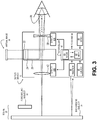
- FIG. 3 shows aspects of an example see-through display device 12 in one embodiment.
- the display device includes illuminator 22 and image former 24.
- the illuminator may comprise a white-light source, such as a white light-emitting diode (LED).
- the illuminator may further comprise suitable optics for collimating the emission of the white-light source and directing the emission to the image former.
- the image former may comprise a rectangular array of light valves, such as a liquid-crystal display (LCD) array.
- the light valves of the array may be arranged to spatially vary and temporally modulate the amount of collimated light transmitted there through, such as to form pixels of the display image.
- the image former may comprise suitable light-filtering elements in registry with the light valves, so that a color display image may be formed.
- the illuminator may comprise one or more modulated lasers, and the image former may be configured to raster the emission of the lasers in synchronicity with the modulation to form the display image.
- image former 24 may comprise a rectangular array of modulated color LED's arranged to form the display image. As the color LED array emits its own light, illuminator 16 may be omitted from the display device.
- image former 24 (and illuminator 22 when present) is operatively coupled to controller 16.
- the controller provides suitable control signals that, when received by the image former, cause the desired display image to be formed.
- the controller may be further configured to execute any control or processing action described herein, and other actions as well.
- image former 24 is arranged to project the display image into see-through multipath optic 26.
- the multipath optic is configured to reflect the display image to pupil 28 of a viewer- viz ., the wearer of the head-mounted display system in which the display device is installed.
- the multipath optic is also configured to transmit to the viewer's pupil an external image of scene 30, arranged external to the display device and opposite the viewer. In this manner, the multipath optic may be configured to guide both the display image and the external image along the same axis A to the pupil.
- Scene 30, as shown in FIG. 3 may include one or more stationary or moving foreground subjects 32.
- the foreground subjects are arranged in front of a background subject 34 -i.e., between the background subject and the display device.
- multipath optic 26 may comprise a partly reflective, partly transmissive structure, as found in an optical beam splitter.
- the multipath optic may comprise a partially silvered mirror.
- the multipath optic may comprise a refractive structure that supports a thin turning film.
- a refractive structure within multipath optic 26 may be configured with optical power. It could be used to guide the display image to pupil 28 at a controlled vergence, such that the display image is provided as a virtual image in a focal plane different from the plane of image former 24.
- the multipath optic may contribute no optical power, and a virtual display image may be formed via the diverging and/or converging power of other optical elements, as described below.
- FIG. 3 an apparent position of a virtual display image is shown, by example, at 36.
- the combined optical power of illuminator 22, image former 24, and multipath optic 26 may be such as to project a virtual display image focused 'at infinity'.
- This configuration absent further converging or diverging optics, may provide a positive see-through display experience when the scene viewed through the display device has a relatively large depth of field. It may provide a less positive experience, however, when the depth of field is shallow.
- the human brain controls the focus of the eye. In sum, the brain is antagonistic to plural background subjects in a scene. Instead of establishing a different focus for background subjects arranged at different depths, the brain will try to use a common focus for all background imagery.
- the display image would appear to float in front of the wall; the wall and the display image would both be resolved without a change in focus of the wearer's eye. If the wearer then places a hand in front of his or her face, resolving the hand would induce a change in focus, and when the hand is in focus, the wall and the virtual display image would appear blurred.
- the brain's attempt to align background imagery is limited by the eye's finite depth of field. If the viewer in the present example moves closer to the wall-e.g., to thirty centimeters-it will be impossible for the same corneal focus to sharply image both the wall and a virtual display image projected at infinity. Continued attempts to do so may cause the viewer to experience eyestrain and headache.
- display device 12 of FIG. 3 is configured to project a virtual display image at an adjustable (i.e., movable) focal plane.
- the focal plane is adjusted dynamically in response to the distance to background subject 34, and to other factors.
- display device 12 includes adaptive diverging lens 38 and diverging lens driver 40A.
- the adaptive diverging lens is one example of an adaptive diverging optic having adjustable optical power. It is arranged between the multipath optic and the viewer's pupil, and is configured to adjustably diverge the display image and the external image such that the display image is brought into focus at a target focal plane.
- the diverging lens driver is operatively coupled to the adaptive diverging lens and configured to adjust the optical power of the lens.
- the focal plane of the virtual display image can be moved back and forth-e.g., from infinity to a finite depth.
- the controller receives one or more forms of input that enable it to determine the desired target position of the focal plane, as discussed further below.
- the focal length of adaptive diverging lens 38 may be varied so as to move the focal plane of the virtual display image between infinity and thirty centimeters at suitably fine intervals- e.g ., continuously or at fixed increments.
- the increments may be arranged linearly in reciprocal space. There may be four, five, ten, or one-hundred increments, for example. In one embodiment, the increments may be arranged in one-half diopter steps.
- the adaptive diverging lens may have a maximum optical power of -4 diopters, for a focal length of 25 centimeters (cm).
- the adaptive diverging lens may comprise a compound stack of diverging lenses, wherein at least one lens has changeable optical power.
- display device 12 also includes adaptive converging lens 42 and converging lens driver 40B.
- the adaptive converging lens is one example of an adaptive converging optic having adjustable optical power. It is arranged at an opposite side of multipath optic 26, relative to the adaptive diverging lens, and is configured to adjustably converge the external image to bring the external image into focus at the target focal plane.
- the converging lens driver is operatively coupled to the adaptive converging lens and is configured to adjust the optical power of the lens.
- the focal length of the adaptive converging lens may be adjusted so that the vergence brought about by the adaptive diverging lens is exactly reversed by the adaptive converging lens, resulting in no optical power being applied to the external image of scene 30.
- the focal lengths of the diverging and converging lenses may be adjusted in sympathy: when one increases ( i.e., becomes more positive), the other decreases ( i.e., becomes more negative).
- the increase and the decrease may be of the same amount. In another embodiment, they may differ to compensate for possible non-idealities.
- such adjustment may also be done in concert-that is to say, with little or no lag between adjustment of the adaptive diverging lens and adjustment of the adaptive converging lens.
- the adjustment may be enacted in a push-pull manner.
- the focal length of adaptive converging lens 42 may be adjusted in concert with that of adaptive diverging lens 38 so that a constant optical power is applied to the external image of the scene. This approach may be used to provide a see-through display experience while also correcting for the viewer's myopia, hyperopia and/or presbyopia, as discussed below.
- adaptive diverging lens 38 and adaptive converging lens 42 may each comprise one or more electro-optically tunable elements.
- Such elements may comprise a material phase having a refractive index that changes in response to an applied electric field.
- the optical power (i.e., the focal length) of the lenses may be varied, controllably, by varying the applied electric field.
- the adaptive lenses may be configured to respond rapidly on the timescale of focal-point accommodation of the human eye-in 75 to 100 milliseconds, for example. This is an advantage over mechanically actuated adaptive lens systems, where the response times may be much greater.
- the rapid response times of the adaptive lenses enable prompt movement of the common focal plane of the display and external images. Furthermore, they enable the adaptive converging lens to accurately 'track' the changing optical power of the adaptive diverging lens, such that the external image is in focus whenever the display image is in focus.
- Adaptive diverging and converging lenses based on electro-optically tunable elements provide other advantages besides rapid response.
- such lenses may be configured to operate on two- to five-volt control signals from drivers 40A and 40B, for compatibility with common logic-device families.
- each electro-optically tunable element may be a thin, light-weight layer having a transparency of about 97 percent in the visible. Accordingly, a stack comprising three such elements could maintain a transparency of 91 percent, and a thickness no greater than 1.5 millimeters.
- multipath optic 26 may be optically coupled (e.g., index matched) to adaptive diverging lens 38 and/or adaptive converging lens 42, for reducing attenuation of the display and/or images.
- one or more of the multipath optic, the adaptive diverging lens, and the adaptive converging lens may support an anti-reflective coating to reduce optical losses.
- an adaptive reflective element such as a mirror, or a combination of refractive and reflective elements may suitably embody the adaptive diverging and converging optics disclosed herein.
- FIG. 3 shows rangefinder 44.
- the rangefinder may be any device responsive to the distance between itself and background subject 34 of the scene.
- the rangefinder may be configured to measure the time period between emitting a pulse and detecting an 'echo'- i.e ., reflected or return pulse.
- the pulse may be sonic or ultrasonic pulse, or a light pulse.
- the rangefinder may acquire an image of the scene illuminated by patterned light. Based on the metrics of the patterned light reflected back to the rangefinder, the distance to the background may be triangulated.
- rangefinder 44 coupled to the front face of display device 12
- the rangefinder may use a technology in which distance to the background is correlated to the angle of intersection between the optical axes of the viewers eyes-e.g., as defined by the orientation of the pupils.
- a rangefinder operating on this principle may be arranged the other side of the display device, opposite the viewer's eyes, so that the orientation of each pupil can be sighted.
- controller 16 may set the target focal plane of the virtual display image to the distance reported by the rangefinder. Accordingly, the depth of the common focal plane of the virtual display image and the external image may be determined based on an output of the rangefinder. It will be understood, however, that other embodiments equally embraced by this disclosure may not include a rangefinder. Rather, controller 16 may be configured to set the focal plane of the display image based on some other criterion, such as an external input from a computer system or application. In other embodiments, even when a rangefinder is included, the external input may be used to set the focal plane of the display image in a manner that supersedes the rangefinder output.
- the rangefinder output may be modified, such that the display image is moved backward or forward based on the external input.
- further processing may be applied in cases where the external input dictates one focal plane, and the rangefinder output dictates another. Such processing may determine a 'compromise' focal plane or establish a priority for resolving the conflicting inputs.
- display device 12 includes linear accelerometer 46 and gyroscopic sensor 48. Coupled anywhere within the head-mounted display system in which the display device is installed, these sensors furnish signals responsive to the viewer's head motion to controller 16. In one embodiment, the controller may determine the appropriate focal plane of the virtual display image based partly on the viewer's head motion, as reported by the sensors. For example, the linear accelerometer may detect when the viewer's head has tilted away from the optical axis of display device 12, indicating that a focal correction of the display image and/or the external image may be desired. Likewise, the gyroscopic sensor may be used to detect a rotation of the viewer's head, suggestive of a change in focus.
- FIG. 4 illustrates an example method 50 for overlaying first and second images in a common focal plane of a viewer.
- the viewer is a wearer of a head-mounted display system.
- the first image is a display image formed in the head-mounted display system
- the second image is an external image of a scene arranged opposite the viewer.
- the external image may include one or more foreground subjects arranged in front of a background subject.
- the display image is formed in the head-mounted display system.
- the display image may be formed in any suitable image former coupled in the display system.
- the image former may project the display image into an infinitely distant focal plane arranged normal to the natural optical axis of the viewer, as defined by the viewer's pupil and retina.
- estimating the distance to the background subject comprises detecting a sonic, ultrasonic, or optical reflection from the background subject, as described above. In another embodiment, estimating the distance to the background subject comprises detecting an orientation of the viewer's pupil or pupils- e.g. , measuring the angle of convergence of the viewer's eyes.
- the estimated distance to the background subject is data that may be received by a controller and used in various ways. For example, it may control or inform the selection of the common focal plane for the display image and the external image, as discussed below. In some embodiments, this data may also be used to control the manner in which the display image is formed- e.g ., at 52 above. It is known, for example, that the left and right eyes align along parallel optical axes only when viewing a subject 'at infinity'. However, as the subject and the viewer approach each other, the optical axes of the left and right eyes converge to intersect at the subject.
- the display image for the left eye may be shifted to the right, and the display image for the right eye may be shifted to the left, as the subject and the viewer approach each other.
- such shifting may be enacted by controller 16, according to the controlling geometric and ocular principles.
- the detected motion may include linear acceleration, as detected via a linear accelerometer.
- the detected motion may include rotation, as detected by a gyroscopic sensor. Accordingly, any rotation or inclination of the viewer's head may be detected.
- the display image is reflected and guided through a multipath optic to the viewer's pupil.
- the display image may be guided from an image former to the viewer's pupil through a ninety-degree reflection at the multipath optic.
- the external image is transmitted and guided through the multipath optic to viewer's pupil.
- the external image may be guided directly through the multipath optic to the viewer's pupil. Accordingly, both the display image and the external are guided from the multipath optic to the viewer's pupil along the same optical axis, as defined by the viewer's pupil and retina.
- the display image is adjustably diverged at an adaptive diverging optic of the display system.
- the level of divergence applied to these images may be such as to move the display image from the infinitely distant focal plane in which it was projected to a target focal depth.
- the target focal depth to which the display image is moved may correspond to a distance between the viewer and a background subject of the external scene. In this manner, the display image may be brought into focus at the common focal plane referred to above.
- the external image is adjustably converged at an adaptive converging optic to bring the second image into focus at the common focal plane.
- the adaptive diverging and converging optics may be actuated in concert, such that the display image and the external image are brought into focus concurrently. Further, the adaptive diverging and converging optics may be actuated in sympathy, such that a vergence of the external image caused by adjustably diverging the display image and the external image is reversed by adjustably converging the external image.
- the divergence imparted to the external image at 62 may be fully reversed at 64, so that no net vergence is applied to the external image.
- the vergence may be reversed incompletely to correct a ocular defect of the viewer-myopia, hyperopia, presbyopia, etc .-which may affect the viewer's resolution of the external image. Accordingly, the actions of 62 and 64 may result in a net vergence being applied to the external image, of an amount suitable to enable the viewer to resolve the external image despite his or her ocular defect.
- various actions may be taken to determine the appropriate level of correction.
- an interface of the head-mounted display system may query the viewer to specify the level of the correction.
- the system may enact a more automatic procedure, wherein the controller progressively varies the level of correction from a myopic limit to a hyperopic limit. The viewer may signal the point at which the level of correction is adequate by tapping the lenses, or in any other suitable manner. From 64 the method returns.
- controller 16 shown schematically in FIG. 3 .
- the controller includes logic subsystem 66 and memory subsystem 68. Through operative coupling of the logic subsystem and the memory subsystem, the controller may be configured to enact any method- i.e ., computation, processing, or control function-described herein.
- memory subsystem 68 may hold instructions that cause logic subsystem 66 to enact the various methods.
- the logic subsystem may include one or more physical devices configured to execute instructions.
- the logic subsystem may be configured to execute instructions that are part of one or more programs, routines, subjects, components, data structures, or other logical constructs. Such instructions may be implemented to perform a task, implement a data type, transform the state of one or more devices, or otherwise arrive at a desired result.
- the logic subsystem may include one or more processors configured to execute software instructions. Additionally or alternatively, the logic subsystem may include one or more hardware or firmware logic machines configured to execute hardware or firmware instructions.
- the logic subsystem may optionally include components distributed among two or more devices, which may be remotely located in some embodiments.
- Memory subsystem 68 may include one or more physical, non-transitory, devices configured to hold data and/or instructions executable by logic subsystem 66 to implement the methods and functions described herein. When such methods and functions are implemented, the state of the memory subsystem may be transformed ( e.g., to hold different data).
- the memory subsystem may include removable media and/or built-in devices.
- the memory subsystem may include optical memory devices, semiconductor memory devices, and/or magnetic memory devices, among others.
- the memory subsystem may include devices with one or more of the following characteristics: volatile, nonvolatile, dynamic, static, read/write, read-only, random access, sequential access, location addressable, file addressable, and content addressable.
- the logic subsystem and the memory subsystem may be integrated into one or more common devices, such as an application-specific integrated circuit (ASIC) or so-called system-on-a-chip.
- the memory subsystem may include computer-system readable removable media, which may be used to store and/or transfer data and/or instructions executable to implement the herein-described methods and processes. Examples of such removable media include CD's, DVD's, HD-DVD's, Blu-Ray Discs, EEPROMs, and/or floppy disks, among others.
- aspects of the instructions described herein may be propagated in a transitory fashion by a pure signal- e.g ., an electromagnetic signal, an optical signal, etc .-that is not held by a physical device for at least a finite duration.
- a pure signal e.g ., an electromagnetic signal, an optical signal, etc .-that is not held by a physical device for at least a finite duration.
- data and/or other forms of information pertaining to the present disclosure may be propagated by a pure signal.
- module and/or 'engine' are used to describe an aspect of controller 16 that is implemented to perform one or more particular functions.
- a module or engine may be instantiated via logic subsystem 66 executing instructions held by memory subsystem 68. It will be understood that different modules and/or engines may be instantiated from the same application, code block, subject, routine, and/or function. Likewise, the same module and/or engine may be instantiated by different applications, code blocks, subjects, routines, and/or functions in some cases.
- controller 16 may include various input devices and various output devices, such as display 12.
- Display 12 may provide a visual representation of data held by memory subsystem 68. As the herein-described methods and processes change the data held by the memory subsystem, and thus transform the state of the memory subsystem, the state of the display may likewise be transformed to visually represent changes in the underlying data.
- the display may include one or more display devices utilizing virtually any type of technology. Such display devices may be combined with logic subsystem 66 and/or memory subsystem 68 in a shared enclosure, or such display devices may be peripheral display devices.
Landscapes
- Physics & Mathematics (AREA)
- General Physics & Mathematics (AREA)
- Optics & Photonics (AREA)
- Optical Modulation, Optical Deflection, Nonlinear Optics, Optical Demodulation, Optical Logic Elements (AREA)
- Display Devices Of Pinball Game Machines (AREA)
- Lenses (AREA)
- Control Of Indicators Other Than Cathode Ray Tubes (AREA)
Applications Claiming Priority (2)
| Application Number | Priority Date | Filing Date | Title |
|---|---|---|---|
| US12/963,547 US8988463B2 (en) | 2010-12-08 | 2010-12-08 | Sympathetic optic adaptation for see-through display |
| PCT/US2011/062433 WO2012078410A1 (en) | 2010-12-08 | 2011-11-29 | Sympathetic optic adaptation for see-through display |
Publications (3)
| Publication Number | Publication Date |
|---|---|
| EP2649485A1 EP2649485A1 (en) | 2013-10-16 |
| EP2649485A4 EP2649485A4 (en) | 2018-01-17 |
| EP2649485B1 true EP2649485B1 (en) | 2020-07-29 |
Family
ID=46198921
Family Applications (1)
| Application Number | Title | Priority Date | Filing Date |
|---|---|---|---|
| EP11846750.5A Active EP2649485B1 (en) | 2010-12-08 | 2011-11-29 | Sympathetic optic adaptation for see-through display |
Country Status (9)
Cited By (1)
| Publication number | Priority date | Publication date | Assignee | Title |
|---|---|---|---|---|
| US11852829B2 (en) | 2020-08-07 | 2023-12-26 | Magic Leap, Inc. | Tunable cylindrical lenses and head-mounted display including the same |
Families Citing this family (66)
| Publication number | Priority date | Publication date | Assignee | Title |
|---|---|---|---|---|
| US9172913B1 (en) * | 2010-09-24 | 2015-10-27 | Jetprotect Corporation | Automatic counter-surveillance detection camera and software |
| ES2387782B1 (es) * | 2011-03-04 | 2013-05-24 | Davalor Consultoria Estrategica Y Tecnologica S.L. | Equipo y procedimiento para exploracion, diagnostico o ayuda al diagnostico y terapia de problemas funcionales de la vision |
| US20130300634A1 (en) * | 2012-05-09 | 2013-11-14 | Nokia Corporation | Method and apparatus for determining representations of displayed information based on focus distance |
| US20130300635A1 (en) * | 2012-05-09 | 2013-11-14 | Nokia Corporation | Method and apparatus for providing focus correction of displayed information |
| JP6007712B2 (ja) * | 2012-09-28 | 2016-10-12 | ブラザー工業株式会社 | ヘッドマウントディスプレイ、それを作動させる方法およびプログラム |
| CN104685409B (zh) | 2012-09-30 | 2017-08-29 | 奥普蒂卡阿姆卡(艾阿)有限公司 | 具有电可调谐功率和对准的透镜 |
| US11126040B2 (en) | 2012-09-30 | 2021-09-21 | Optica Amuka (A.A.) Ltd. | Electrically-tunable lenses and lens systems |
| TWI481901B (zh) * | 2012-12-03 | 2015-04-21 | Wistron Corp | 頭戴式顯示裝置 |
| JP5967597B2 (ja) * | 2013-06-19 | 2016-08-10 | パナソニックIpマネジメント株式会社 | 画像表示装置および画像表示方法 |
| KR102378457B1 (ko) | 2013-11-27 | 2022-03-23 | 매직 립, 인코포레이티드 | 가상 및 증강 현실 시스템들 및 방법들 |
| JP2015115848A (ja) * | 2013-12-13 | 2015-06-22 | セイコーエプソン株式会社 | 頭部装着型表示装置および頭部装着型表示装置の制御方法 |
| EP2887124A1 (en) * | 2013-12-20 | 2015-06-24 | Thomson Licensing | Optical see-through glass type display device and corresponding optical unit |
| US10216271B2 (en) | 2014-05-15 | 2019-02-26 | Atheer, Inc. | Method and apparatus for independent control of focal vergence and emphasis of displayed and transmitted optical content |
| US9500868B2 (en) * | 2014-07-10 | 2016-11-22 | Honeywell International Inc. | Space suit helmet display system |
| JP6294780B2 (ja) * | 2014-07-17 | 2018-03-14 | 株式会社ソニー・インタラクティブエンタテインメント | 立体画像提示装置、立体画像提示方法、およびヘッドマウントディスプレイ |
| CN105589197A (zh) * | 2014-10-20 | 2016-05-18 | 深圳市亿思达科技集团有限公司 | 可以调节显示图像的间距的智能眼镜 |
| FR3028326B1 (fr) * | 2014-11-07 | 2018-08-17 | Thales | Systeme de visualisation de tete comportant un systeme oculometrique et des moyens d'adaptation des images emises |
| NZ773834A (en) | 2015-03-16 | 2022-07-01 | Magic Leap Inc | Methods and systems for diagnosing and treating health ailments |
| JP2018523147A (ja) * | 2015-05-08 | 2018-08-16 | ビ−エイイ− システムズ パブリック リミテッド カンパニ−BAE SYSTEMS plc | ディスプレイにおける、および、ディスプレイに関連する改良 |
| EP3091740A1 (en) * | 2015-05-08 | 2016-11-09 | BAE Systems PLC | Improvements in and relating to displays |
| US9848127B2 (en) | 2015-07-14 | 2017-12-19 | Honeywell International Inc. | System and method for a compact display |
| US10007115B2 (en) | 2015-08-12 | 2018-06-26 | Daqri, Llc | Placement of a computer generated display with focal plane at finite distance using optical devices and a see-through head-mounted display incorporating the same |
| US9298283B1 (en) | 2015-09-10 | 2016-03-29 | Connectivity Labs Inc. | Sedentary virtual reality method and systems |
| CN105435379B (zh) * | 2015-12-29 | 2018-11-02 | 深圳先进技术研究院 | 基于二维面阵探头的视网膜刺激设备 |
| CN105662704B (zh) * | 2015-12-29 | 2017-10-20 | 深圳先进技术研究院 | 超声视网膜刺激设备 |
| KR102530558B1 (ko) | 2016-03-16 | 2023-05-09 | 삼성전자주식회사 | 투시형 디스플레이 장치 |
| IL299497B2 (en) | 2016-04-08 | 2024-02-01 | Magic Leap Inc | Augmented reality systems and methods with variable focus lens elements |
| ES2904889T3 (es) | 2016-04-17 | 2022-04-06 | Optica Amuka A A Ltd | Lente para gafas que comprende una lente de cristal líquido con accionamiento eléctrico mejorado |
| US11360330B2 (en) | 2016-06-16 | 2022-06-14 | Optica Amuka (A.A.) Ltd. | Tunable lenses for spectacles |
| US20180003991A1 (en) * | 2016-07-01 | 2018-01-04 | Intel Corporation | Image alignment in head worn display |
| US10649209B2 (en) | 2016-07-08 | 2020-05-12 | Daqri Llc | Optical combiner apparatus |
| KR102715030B1 (ko) * | 2016-07-26 | 2024-10-10 | 삼성전자주식회사 | 투시형 디스플레이 장치 |
| KR102800326B1 (ko) | 2016-10-19 | 2025-04-28 | 삼성전자주식회사 | 렌즈 유닛 및 이를 포함하는 투시형 디스플레이 장치 |
| US10481678B2 (en) | 2017-01-11 | 2019-11-19 | Daqri Llc | Interface-based modeling and design of three dimensional spaces using two dimensional representations |
| KR101958366B1 (ko) * | 2017-02-21 | 2019-03-18 | 주식회사 첸트랄 | 영상 표시 장치용 원방시 구현 안경 |
| KR102483970B1 (ko) | 2017-02-23 | 2022-12-30 | 매직 립, 인코포레이티드 | 편광 변환에 기초한 가변-포커스 가상 이미지 디바이스들 |
| IL310618A (en) | 2017-03-22 | 2024-04-01 | Magic Leap Inc | A variable focus display system with a dynamic field of view |
| KR102708488B1 (ko) | 2017-06-12 | 2024-09-20 | 매직 립, 인코포레이티드 | 깊이 평면들을 변경하기 위한 다중-엘리먼트 적응형 렌즈를 갖는 증강 현실 디스플레이 |
| US11747619B2 (en) | 2017-07-10 | 2023-09-05 | Optica Amuka (A.A.) Ltd. | Virtual reality and augmented reality systems with dynamic vision correction |
| US11953764B2 (en) | 2017-07-10 | 2024-04-09 | Optica Amuka (A.A.) Ltd. | Tunable lenses with enhanced performance features |
| KR102481884B1 (ko) | 2017-09-22 | 2022-12-28 | 삼성전자주식회사 | 가상 영상을 표시하는 방법 및 장치 |
| CN207181829U (zh) * | 2017-09-25 | 2018-04-03 | 京东方科技集团股份有限公司 | 虚拟现实头盔 |
| KR102845933B1 (ko) | 2017-10-11 | 2025-08-12 | 매직 립, 인코포레이티드 | 투명 발광 디스플레이를 갖는 접안렌즈를 포함하는 증강 현실 디스플레이 |
| EP3698212A4 (en) | 2017-10-16 | 2021-07-14 | Optica Amuka (A.A.) Ltd. | ELECTRICALLY TUNING GLASSES THAT CAN BE CONTROLLED BY AN EXTERNAL SYSTEM |
| KR102845935B1 (ko) | 2017-10-26 | 2025-08-13 | 매직 립, 인코포레이티드 | 증강 현실 디스플레이를 위한 광대역 적응형 렌즈 어셈블리 |
| GB201800933D0 (en) * | 2018-01-19 | 2018-03-07 | Adlens Ipr Ltd | Improvements in or relating to variable focal power optical elements,a variable focal power optical device, a display module for augmented reality headset |
| WO2019173390A1 (en) * | 2018-03-07 | 2019-09-12 | Magic Leap, Inc. | Adaptive lens assemblies including polarization-selective lens stacks for augmented reality display |
| EP4276520B1 (en) | 2018-08-31 | 2025-04-23 | Magic Leap, Inc. | Spatially-resolved dynamic dimming for augmented reality device |
| US11221494B2 (en) | 2018-12-10 | 2022-01-11 | Facebook Technologies, Llc | Adaptive viewport optical display systems and methods |
| US11125993B2 (en) | 2018-12-10 | 2021-09-21 | Facebook Technologies, Llc | Optical hyperfocal reflective systems and methods, and augmented reality and/or virtual reality displays incorporating same |
| JP2020095215A (ja) * | 2018-12-14 | 2020-06-18 | 株式会社ジャパンディスプレイ | 表示装置及びヘルメット |
| EP3908878A4 (en) | 2019-01-09 | 2022-04-06 | Facebook Technologies, LLC | NON-UNIFORM SUB-PUPIL REFLECTORS AND METHODS IN OPTICAL WAVEGUIDES FOR AR, HMD, AND HUD APPLICATIONS |
| CN119902373A (zh) | 2019-01-11 | 2025-04-29 | 奇跃公司 | 各种深度处的虚拟内容的时间复用显示 |
| CN116249918A (zh) | 2019-05-24 | 2023-06-09 | 奇跃公司 | 可变焦组件 |
| CN113906333A (zh) | 2019-06-02 | 2022-01-07 | 奥普蒂卡阿姆卡(艾阿)有限公司 | 用于近视治疗的电可调谐助视器 |
| JP2021056369A (ja) * | 2019-09-30 | 2021-04-08 | セイコーエプソン株式会社 | ヘッドマウントディスプレイ |
| KR102476727B1 (ko) * | 2019-12-27 | 2022-12-12 | 한국광기술원 | 착용자의 시력을 보정할 수 있는 증강현실 광학시스템 |
| JP2021184050A (ja) * | 2020-05-22 | 2021-12-02 | 株式会社日立エルジーデータストレージ | 映像表示装置、ヘッドマウントディスプレイ |
| CN111629198B (zh) * | 2020-06-08 | 2022-08-09 | 京东方科技集团股份有限公司 | 成像系统及其控制方法、控制装置和存储介质 |
| EP4308996A4 (en) | 2021-03-15 | 2024-10-09 | Magic Leap, Inc. | HEAD-MOUNTED OPTICAL DEVICES AND DISPLAY DEVICES USING TUNABLE CYLINDRICAL LENSES |
| CN113671812B (zh) * | 2021-09-14 | 2022-10-28 | 中国联合网络通信集团有限公司 | 全息影像成像方法、全息投影设备、观测设备及系统 |
| WO2023055861A1 (en) * | 2021-09-28 | 2023-04-06 | Light Field Lab, Inc. | Relay systems |
| US11863730B2 (en) | 2021-12-07 | 2024-01-02 | Snap Inc. | Optical waveguide combiner systems and methods |
| US11614619B1 (en) | 2022-04-11 | 2023-03-28 | Voyetra Turtle Beach, Inc. | Headset dynamic windowing |
| CN114815217B (zh) * | 2022-05-06 | 2024-06-11 | 山东北方光学电子有限公司 | 多功能头盔眼镜微光和显示器件同步成像控制电路和使用方法 |
| EP4280179A1 (en) * | 2022-05-20 | 2023-11-22 | Tata Consultancy Services Limited | Method and system for detecting and extracting price region from digital flyers and promotions |
Family Cites Families (26)
| Publication number | Priority date | Publication date | Assignee | Title |
|---|---|---|---|---|
| FR2704951B1 (fr) * | 1993-05-05 | 1995-07-21 | Particulier Editions | Dispositif de formation d'image autostereoscopique. |
| US6177952B1 (en) * | 1993-09-17 | 2001-01-23 | Olympic Optical Co., Ltd. | Imaging apparatus, image display apparatus and image recording and/or reproducing apparatus |
| JPH08160344A (ja) | 1994-12-05 | 1996-06-21 | Olympus Optical Co Ltd | 頭部装着式映像表示装置 |
| JPH09211374A (ja) | 1996-01-31 | 1997-08-15 | Nikon Corp | ヘッドマウントディスプレイ装置 |
| US6204974B1 (en) * | 1996-10-08 | 2001-03-20 | The Microoptical Corporation | Compact image display system for eyeglasses or other head-borne frames |
| JP2001056446A (ja) * | 1999-08-18 | 2001-02-27 | Sharp Corp | ヘッドマウントディスプレイ装置 |
| ES2348532T3 (es) * | 2000-06-05 | 2010-12-09 | Lumus Ltd | Dilatador de haces opticos guiado por un sustrato. |
| US6747611B1 (en) | 2000-07-27 | 2004-06-08 | International Business Machines Corporation | Compact optical system and packaging for head mounted display |
| KR20020022519A (ko) * | 2000-09-20 | 2002-03-27 | 송혁규 | 헤드 마운티드 디스플레이 장치의 헤드셋 |
| AU2002361572A1 (en) | 2001-10-19 | 2003-04-28 | University Of North Carolina At Chape Hill | Methods and systems for dynamic virtual convergence and head mountable display |
| DE10306578A1 (de) * | 2003-02-17 | 2004-08-26 | Carl Zeiss | Anzeigevorrichtung mit elektrooptischer Fokussierung |
| JP2005223752A (ja) * | 2004-02-06 | 2005-08-18 | Olympus Corp | 視度調整用レンズ付頭部装着型カメラ |
| JP4605152B2 (ja) | 2004-03-12 | 2011-01-05 | 株式会社ニコン | 画像表示光学系及び画像表示装置 |
| US7403337B2 (en) | 2004-05-11 | 2008-07-22 | Universal Vision Biotechnology Co., Ltd. | Focus adjustable head mounted display system and method and device for realizing the system |
| WO2005121707A2 (en) * | 2004-06-03 | 2005-12-22 | Making Virtual Solid, L.L.C. | En-route navigation display method and apparatus using head-up display |
| US8248458B2 (en) * | 2004-08-06 | 2012-08-21 | University Of Washington Through Its Center For Commercialization | Variable fixation viewing distance scanned light displays |
| US7656775B2 (en) * | 2004-11-15 | 2010-02-02 | Panasonic Corporation | Optical head, and information recording-and-regeneration apparatus |
| CN100538437C (zh) | 2005-02-23 | 2009-09-09 | 北京理工大学 | 一种头盔显示器的光学系统 |
| US20060250322A1 (en) | 2005-05-09 | 2006-11-09 | Optics 1, Inc. | Dynamic vergence and focus control for head-mounted displays |
| JP2008256946A (ja) | 2007-04-05 | 2008-10-23 | Tokyo Institute Of Technology | 画像表示装置のための酔い防止装置 |
| CN101029968A (zh) | 2007-04-06 | 2007-09-05 | 北京理工大学 | 可寻址光线屏蔽机制光学透视式头盔显示器 |
| KR20090052169A (ko) | 2007-11-20 | 2009-05-25 | 삼성전자주식회사 | 두부(頭部) 장착 디스플레이 |
| JP4858512B2 (ja) | 2008-08-21 | 2012-01-18 | ソニー株式会社 | 頭部装着型ディスプレイ |
| US8957835B2 (en) | 2008-09-30 | 2015-02-17 | Apple Inc. | Head-mounted display apparatus for retaining a portable electronic device with display |
| JP4636164B2 (ja) | 2008-10-23 | 2011-02-23 | ソニー株式会社 | 頭部装着型ディスプレイ |
| US8749884B2 (en) * | 2010-05-04 | 2014-06-10 | Omid Jahromi | Telescopic gun sight free of parallax error |
-
2010
- 2010-12-08 US US12/963,547 patent/US8988463B2/en active Active
-
2011
- 2011-11-03 TW TW100140153A patent/TWI526715B/zh not_active IP Right Cessation
- 2011-11-29 WO PCT/US2011/062433 patent/WO2012078410A1/en unknown
- 2011-11-29 EP EP11846750.5A patent/EP2649485B1/en active Active
- 2011-11-29 CA CA2817226A patent/CA2817226C/en active Active
- 2011-11-29 JP JP2013543208A patent/JP6018579B2/ja not_active Expired - Fee Related
- 2011-11-29 KR KR1020137014585A patent/KR101878520B1/ko active Active
- 2011-12-06 AR ARP110104577A patent/AR084189A1/es active IP Right Grant
- 2011-12-08 CN CN201110430502.4A patent/CN102540466B/zh active Active
Non-Patent Citations (1)
| Title |
|---|
| None * |
Cited By (1)
| Publication number | Priority date | Publication date | Assignee | Title |
|---|---|---|---|---|
| US11852829B2 (en) | 2020-08-07 | 2023-12-26 | Magic Leap, Inc. | Tunable cylindrical lenses and head-mounted display including the same |
Also Published As
| Publication number | Publication date |
|---|---|
| US8988463B2 (en) | 2015-03-24 |
| AR084189A1 (es) | 2013-04-24 |
| TW201232034A (en) | 2012-08-01 |
| CN102540466A (zh) | 2012-07-04 |
| CA2817226C (en) | 2018-10-16 |
| JP6018579B2 (ja) | 2016-11-02 |
| WO2012078410A1 (en) | 2012-06-14 |
| KR20130130735A (ko) | 2013-12-02 |
| CN102540466B (zh) | 2014-07-09 |
| JP2014505899A (ja) | 2014-03-06 |
| US20120147038A1 (en) | 2012-06-14 |
| KR101878520B1 (ko) | 2018-07-13 |
| EP2649485A1 (en) | 2013-10-16 |
| CA2817226A1 (en) | 2012-06-14 |
| TWI526715B (zh) | 2016-03-21 |
| EP2649485A4 (en) | 2018-01-17 |
Similar Documents
| Publication | Publication Date | Title |
|---|---|---|
| EP2649485B1 (en) | Sympathetic optic adaptation for see-through display | |
| US9298012B2 (en) | Eyebox adjustment for interpupillary distance | |
| JP6502586B2 (ja) | 焦点調整するバーチャルリアリティヘッドセット | |
| US11106276B2 (en) | Focus adjusting headset | |
| CN109073897B (zh) | 用于为电子信息装置提供显示装置的方法 | |
| JP4155343B2 (ja) | 二つの光景からの光を観察者の眼へ代替的に、あるいは同時に導くための光学系 | |
| HK1245897A1 (en) | Display apparatus and method of displaying using the display apparatus | |
| HK1245897B (zh) | 显示装置及使用该显示装置进行显示的方法 | |
| CN113196141B (zh) | 使用分段相位剖面液晶透镜的光学系统 | |
| CN111077670B (zh) | 光传递模块以及头戴式显示装置 | |
| EP4342177B1 (en) | Autocalibrated near-eye display | |
| EP3497508A1 (en) | A near-eye display system including a modulation stack | |
| US10412378B2 (en) | Resonating optical waveguide using multiple diffractive optical elements | |
| EP3179289B1 (en) | Focus adjusting virtual reality headset | |
| CN110618529A (zh) | 用于增强现实的光场显示系统和增强现实装置 | |
| US10620432B1 (en) | Devices and methods for lens position adjustment based on diffraction in a fresnel lens | |
| HK1188299B (en) | Sympathetic optic adaptation for see-through display | |
| HK1188299A (en) | Sympathetic optic adaptation for see-through display | |
| US10948631B1 (en) | Optical systems and methods for increasing interpupillary distance of a display device | |
| US10520729B1 (en) | Light scattering element for providing optical cues for lens position adjustment |
Legal Events
| Date | Code | Title | Description |
|---|---|---|---|
| PUAI | Public reference made under article 153(3) epc to a published international application that has entered the european phase |
Free format text: ORIGINAL CODE: 0009012 |
|
| 17P | Request for examination filed |
Effective date: 20130523 |
|
| AK | Designated contracting states |
Kind code of ref document: A1 Designated state(s): AL AT BE BG CH CY CZ DE DK EE ES FI FR GB GR HR HU IE IS IT LI LT LU LV MC MK MT NL NO PL PT RO RS SE SI SK SM TR |
|
| DAX | Request for extension of the european patent (deleted) | ||
| REG | Reference to a national code |
Ref country code: HK Ref legal event code: DE Ref document number: 1188299 Country of ref document: HK |
|
| RAP1 | Party data changed (applicant data changed or rights of an application transferred) |
Owner name: MICROSOFT TECHNOLOGY LICENSING, LLC |
|
| RA4 | Supplementary search report drawn up and despatched (corrected) |
Effective date: 20171218 |
|
| RIC1 | Information provided on ipc code assigned before grant |
Ipc: G02B 27/01 20060101AFI20171212BHEP |
|
| STAA | Information on the status of an ep patent application or granted ep patent |
Free format text: STATUS: EXAMINATION IS IN PROGRESS |
|
| 17Q | First examination report despatched |
Effective date: 20180223 |
|
| R17C | First examination report despatched (corrected) |
Effective date: 20180223 |
|
| GRAP | Despatch of communication of intention to grant a patent |
Free format text: ORIGINAL CODE: EPIDOSNIGR1 |
|
| STAA | Information on the status of an ep patent application or granted ep patent |
Free format text: STATUS: GRANT OF PATENT IS INTENDED |
|
| INTG | Intention to grant announced |
Effective date: 20200302 |
|
| GRAS | Grant fee paid |
Free format text: ORIGINAL CODE: EPIDOSNIGR3 |
|
| GRAA | (expected) grant |
Free format text: ORIGINAL CODE: 0009210 |
|
| STAA | Information on the status of an ep patent application or granted ep patent |
Free format text: STATUS: THE PATENT HAS BEEN GRANTED |
|
| AK | Designated contracting states |
Kind code of ref document: B1 Designated state(s): AL AT BE BG CH CY CZ DE DK EE ES FI FR GB GR HR HU IE IS IT LI LT LU LV MC MK MT NL NO PL PT RO RS SE SI SK SM TR |
|
| REG | Reference to a national code |
Ref country code: GB Ref legal event code: FG4D |
|
| REG | Reference to a national code |
Ref country code: CH Ref legal event code: EP |
|
| REG | Reference to a national code |
Ref country code: AT Ref legal event code: REF Ref document number: 1296471 Country of ref document: AT Kind code of ref document: T Effective date: 20200815 |
|
| REG | Reference to a national code |
Ref country code: IE Ref legal event code: FG4D |
|
| REG | Reference to a national code |
Ref country code: DE Ref legal event code: R096 Ref document number: 602011068015 Country of ref document: DE |
|
| REG | Reference to a national code |
Ref country code: LT Ref legal event code: MG4D |
|
| REG | Reference to a national code |
Ref country code: NL Ref legal event code: MP Effective date: 20200729 |
|
| REG | Reference to a national code |
Ref country code: AT Ref legal event code: MK05 Ref document number: 1296471 Country of ref document: AT Kind code of ref document: T Effective date: 20200729 |
|
| PG25 | Lapsed in a contracting state [announced via postgrant information from national office to epo] |
Ref country code: AT Free format text: LAPSE BECAUSE OF FAILURE TO SUBMIT A TRANSLATION OF THE DESCRIPTION OR TO PAY THE FEE WITHIN THE PRESCRIBED TIME-LIMIT Effective date: 20200729 Ref country code: HR Free format text: LAPSE BECAUSE OF FAILURE TO SUBMIT A TRANSLATION OF THE DESCRIPTION OR TO PAY THE FEE WITHIN THE PRESCRIBED TIME-LIMIT Effective date: 20200729 Ref country code: SE Free format text: LAPSE BECAUSE OF FAILURE TO SUBMIT A TRANSLATION OF THE DESCRIPTION OR TO PAY THE FEE WITHIN THE PRESCRIBED TIME-LIMIT Effective date: 20200729 Ref country code: BG Free format text: LAPSE BECAUSE OF FAILURE TO SUBMIT A TRANSLATION OF THE DESCRIPTION OR TO PAY THE FEE WITHIN THE PRESCRIBED TIME-LIMIT Effective date: 20201029 Ref country code: LT Free format text: LAPSE BECAUSE OF FAILURE TO SUBMIT A TRANSLATION OF THE DESCRIPTION OR TO PAY THE FEE WITHIN THE PRESCRIBED TIME-LIMIT Effective date: 20200729 Ref country code: ES Free format text: LAPSE BECAUSE OF FAILURE TO SUBMIT A TRANSLATION OF THE DESCRIPTION OR TO PAY THE FEE WITHIN THE PRESCRIBED TIME-LIMIT Effective date: 20200729 Ref country code: PT Free format text: LAPSE BECAUSE OF FAILURE TO SUBMIT A TRANSLATION OF THE DESCRIPTION OR TO PAY THE FEE WITHIN THE PRESCRIBED TIME-LIMIT Effective date: 20201130 Ref country code: FI Free format text: LAPSE BECAUSE OF FAILURE TO SUBMIT A TRANSLATION OF THE DESCRIPTION OR TO PAY THE FEE WITHIN THE PRESCRIBED TIME-LIMIT Effective date: 20200729 Ref country code: GR Free format text: LAPSE BECAUSE OF FAILURE TO SUBMIT A TRANSLATION OF THE DESCRIPTION OR TO PAY THE FEE WITHIN THE PRESCRIBED TIME-LIMIT Effective date: 20201030 Ref country code: NO Free format text: LAPSE BECAUSE OF FAILURE TO SUBMIT A TRANSLATION OF THE DESCRIPTION OR TO PAY THE FEE WITHIN THE PRESCRIBED TIME-LIMIT Effective date: 20201029 |
|
| PG25 | Lapsed in a contracting state [announced via postgrant information from national office to epo] |
Ref country code: LV Free format text: LAPSE BECAUSE OF FAILURE TO SUBMIT A TRANSLATION OF THE DESCRIPTION OR TO PAY THE FEE WITHIN THE PRESCRIBED TIME-LIMIT Effective date: 20200729 Ref country code: RS Free format text: LAPSE BECAUSE OF FAILURE TO SUBMIT A TRANSLATION OF THE DESCRIPTION OR TO PAY THE FEE WITHIN THE PRESCRIBED TIME-LIMIT Effective date: 20200729 Ref country code: PL Free format text: LAPSE BECAUSE OF FAILURE TO SUBMIT A TRANSLATION OF THE DESCRIPTION OR TO PAY THE FEE WITHIN THE PRESCRIBED TIME-LIMIT Effective date: 20200729 Ref country code: IS Free format text: LAPSE BECAUSE OF FAILURE TO SUBMIT A TRANSLATION OF THE DESCRIPTION OR TO PAY THE FEE WITHIN THE PRESCRIBED TIME-LIMIT Effective date: 20201129 |
|
| PG25 | Lapsed in a contracting state [announced via postgrant information from national office to epo] |
Ref country code: NL Free format text: LAPSE BECAUSE OF FAILURE TO SUBMIT A TRANSLATION OF THE DESCRIPTION OR TO PAY THE FEE WITHIN THE PRESCRIBED TIME-LIMIT Effective date: 20200729 |
|
| PG25 | Lapsed in a contracting state [announced via postgrant information from national office to epo] |
Ref country code: IT Free format text: LAPSE BECAUSE OF FAILURE TO SUBMIT A TRANSLATION OF THE DESCRIPTION OR TO PAY THE FEE WITHIN THE PRESCRIBED TIME-LIMIT Effective date: 20200729 Ref country code: CZ Free format text: LAPSE BECAUSE OF FAILURE TO SUBMIT A TRANSLATION OF THE DESCRIPTION OR TO PAY THE FEE WITHIN THE PRESCRIBED TIME-LIMIT Effective date: 20200729 Ref country code: DK Free format text: LAPSE BECAUSE OF FAILURE TO SUBMIT A TRANSLATION OF THE DESCRIPTION OR TO PAY THE FEE WITHIN THE PRESCRIBED TIME-LIMIT Effective date: 20200729 Ref country code: EE Free format text: LAPSE BECAUSE OF FAILURE TO SUBMIT A TRANSLATION OF THE DESCRIPTION OR TO PAY THE FEE WITHIN THE PRESCRIBED TIME-LIMIT Effective date: 20200729 Ref country code: RO Free format text: LAPSE BECAUSE OF FAILURE TO SUBMIT A TRANSLATION OF THE DESCRIPTION OR TO PAY THE FEE WITHIN THE PRESCRIBED TIME-LIMIT Effective date: 20200729 Ref country code: SM Free format text: LAPSE BECAUSE OF FAILURE TO SUBMIT A TRANSLATION OF THE DESCRIPTION OR TO PAY THE FEE WITHIN THE PRESCRIBED TIME-LIMIT Effective date: 20200729 |
|
| REG | Reference to a national code |
Ref country code: DE Ref legal event code: R097 Ref document number: 602011068015 Country of ref document: DE |
|
| PG25 | Lapsed in a contracting state [announced via postgrant information from national office to epo] |
Ref country code: AL Free format text: LAPSE BECAUSE OF FAILURE TO SUBMIT A TRANSLATION OF THE DESCRIPTION OR TO PAY THE FEE WITHIN THE PRESCRIBED TIME-LIMIT Effective date: 20200729 |
|
| PLBE | No opposition filed within time limit |
Free format text: ORIGINAL CODE: 0009261 |
|
| STAA | Information on the status of an ep patent application or granted ep patent |
Free format text: STATUS: NO OPPOSITION FILED WITHIN TIME LIMIT |
|
| PG25 | Lapsed in a contracting state [announced via postgrant information from national office to epo] |
Ref country code: MC Free format text: LAPSE BECAUSE OF FAILURE TO SUBMIT A TRANSLATION OF THE DESCRIPTION OR TO PAY THE FEE WITHIN THE PRESCRIBED TIME-LIMIT Effective date: 20200729 Ref country code: SK Free format text: LAPSE BECAUSE OF FAILURE TO SUBMIT A TRANSLATION OF THE DESCRIPTION OR TO PAY THE FEE WITHIN THE PRESCRIBED TIME-LIMIT Effective date: 20200729 |
|
| REG | Reference to a national code |
Ref country code: CH Ref legal event code: PL |
|
| 26N | No opposition filed |
Effective date: 20210430 |
|
| PG25 | Lapsed in a contracting state [announced via postgrant information from national office to epo] |
Ref country code: LU Free format text: LAPSE BECAUSE OF NON-PAYMENT OF DUE FEES Effective date: 20201129 |
|
| REG | Reference to a national code |
Ref country code: BE Ref legal event code: MM Effective date: 20201130 |
|
| PG25 | Lapsed in a contracting state [announced via postgrant information from national office to epo] |
Ref country code: LI Free format text: LAPSE BECAUSE OF NON-PAYMENT OF DUE FEES Effective date: 20201130 Ref country code: SI Free format text: LAPSE BECAUSE OF FAILURE TO SUBMIT A TRANSLATION OF THE DESCRIPTION OR TO PAY THE FEE WITHIN THE PRESCRIBED TIME-LIMIT Effective date: 20200729 Ref country code: CH Free format text: LAPSE BECAUSE OF NON-PAYMENT OF DUE FEES Effective date: 20201130 |
|
| REG | Reference to a national code |
Ref country code: IE Ref legal event code: MM4A |
|
| PG25 | Lapsed in a contracting state [announced via postgrant information from national office to epo] |
Ref country code: IE Free format text: LAPSE BECAUSE OF NON-PAYMENT OF DUE FEES Effective date: 20201129 |
|
| PG25 | Lapsed in a contracting state [announced via postgrant information from national office to epo] |
Ref country code: TR Free format text: LAPSE BECAUSE OF FAILURE TO SUBMIT A TRANSLATION OF THE DESCRIPTION OR TO PAY THE FEE WITHIN THE PRESCRIBED TIME-LIMIT Effective date: 20200729 Ref country code: MT Free format text: LAPSE BECAUSE OF FAILURE TO SUBMIT A TRANSLATION OF THE DESCRIPTION OR TO PAY THE FEE WITHIN THE PRESCRIBED TIME-LIMIT Effective date: 20200729 Ref country code: CY Free format text: LAPSE BECAUSE OF FAILURE TO SUBMIT A TRANSLATION OF THE DESCRIPTION OR TO PAY THE FEE WITHIN THE PRESCRIBED TIME-LIMIT Effective date: 20200729 |
|
| PG25 | Lapsed in a contracting state [announced via postgrant information from national office to epo] |
Ref country code: MK Free format text: LAPSE BECAUSE OF FAILURE TO SUBMIT A TRANSLATION OF THE DESCRIPTION OR TO PAY THE FEE WITHIN THE PRESCRIBED TIME-LIMIT Effective date: 20200729 |
|
| PG25 | Lapsed in a contracting state [announced via postgrant information from national office to epo] |
Ref country code: BE Free format text: LAPSE BECAUSE OF NON-PAYMENT OF DUE FEES Effective date: 20201130 |
|
| P01 | Opt-out of the competence of the unified patent court (upc) registered |
Effective date: 20230501 |
|
| PGFP | Annual fee paid to national office [announced via postgrant information from national office to epo] |
Ref country code: GB Payment date: 20231019 Year of fee payment: 13 |
|
| PGFP | Annual fee paid to national office [announced via postgrant information from national office to epo] |
Ref country code: FR Payment date: 20231019 Year of fee payment: 13 Ref country code: DE Payment date: 20231019 Year of fee payment: 13 |
|
| REG | Reference to a national code |
Ref country code: DE Ref legal event code: R119 Ref document number: 602011068015 Country of ref document: DE |
|
| GBPC | Gb: european patent ceased through non-payment of renewal fee |
Effective date: 20241129 |