EP2648899B1 - Presse zum pressen eines materials - Google Patents
Presse zum pressen eines materials Download PDFInfo
- Publication number
- EP2648899B1 EP2648899B1 EP11791515.7A EP11791515A EP2648899B1 EP 2648899 B1 EP2648899 B1 EP 2648899B1 EP 11791515 A EP11791515 A EP 11791515A EP 2648899 B1 EP2648899 B1 EP 2648899B1
- Authority
- EP
- European Patent Office
- Prior art keywords
- bearing unit
- press
- bearing
- roller
- lubricant
- Prior art date
- Legal status (The legal status is an assumption and is not a legal conclusion. Google has not performed a legal analysis and makes no representation as to the accuracy of the status listed.)
- Active
Links
Images


Classifications
-
- B—PERFORMING OPERATIONS; TRANSPORTING
- B30—PRESSES
- B30B—PRESSES IN GENERAL
- B30B11/00—Presses specially adapted for forming shaped articles from material in particulate or plastic state, e.g. briquetting presses, tabletting presses
- B30B11/20—Roller-and-ring machines, i.e. with roller disposed within a ring and co-operating with the inner surface of the ring
- B30B11/201—Roller-and-ring machines, i.e. with roller disposed within a ring and co-operating with the inner surface of the ring for extruding material
- B30B11/208—Roller constructions; Mounting of the rollers
-
- F—MECHANICAL ENGINEERING; LIGHTING; HEATING; WEAPONS; BLASTING
- F16—ENGINEERING ELEMENTS AND UNITS; GENERAL MEASURES FOR PRODUCING AND MAINTAINING EFFECTIVE FUNCTIONING OF MACHINES OR INSTALLATIONS; THERMAL INSULATION IN GENERAL
- F16C—SHAFTS; FLEXIBLE SHAFTS; ELEMENTS OR CRANKSHAFT MECHANISMS; ROTARY BODIES OTHER THAN GEARING ELEMENTS; BEARINGS
- F16C13/00—Rolls, drums, discs, or the like; Bearings or mountings therefor
- F16C13/02—Bearings
-
- F—MECHANICAL ENGINEERING; LIGHTING; HEATING; WEAPONS; BLASTING
- F16—ENGINEERING ELEMENTS AND UNITS; GENERAL MEASURES FOR PRODUCING AND MAINTAINING EFFECTIVE FUNCTIONING OF MACHINES OR INSTALLATIONS; THERMAL INSULATION IN GENERAL
- F16C—SHAFTS; FLEXIBLE SHAFTS; ELEMENTS OR CRANKSHAFT MECHANISMS; ROTARY BODIES OTHER THAN GEARING ELEMENTS; BEARINGS
- F16C19/00—Bearings with rolling contact, for exclusively rotary movement
- F16C19/22—Bearings with rolling contact, for exclusively rotary movement with bearing rollers essentially of the same size in one or more circular rows, e.g. needle bearings
- F16C19/34—Bearings with rolling contact, for exclusively rotary movement with bearing rollers essentially of the same size in one or more circular rows, e.g. needle bearings for both radial and axial load
- F16C19/38—Bearings with rolling contact, for exclusively rotary movement with bearing rollers essentially of the same size in one or more circular rows, e.g. needle bearings for both radial and axial load with two or more rows of rollers
- F16C19/383—Bearings with rolling contact, for exclusively rotary movement with bearing rollers essentially of the same size in one or more circular rows, e.g. needle bearings for both radial and axial load with two or more rows of rollers with tapered rollers, i.e. rollers having essentially the shape of a truncated cone
- F16C19/385—Bearings with rolling contact, for exclusively rotary movement with bearing rollers essentially of the same size in one or more circular rows, e.g. needle bearings for both radial and axial load with two or more rows of rollers with tapered rollers, i.e. rollers having essentially the shape of a truncated cone with two rows, i.e. double-row tapered roller bearings
- F16C19/386—Bearings with rolling contact, for exclusively rotary movement with bearing rollers essentially of the same size in one or more circular rows, e.g. needle bearings for both radial and axial load with two or more rows of rollers with tapered rollers, i.e. rollers having essentially the shape of a truncated cone with two rows, i.e. double-row tapered roller bearings in O-arrangement
-
- F—MECHANICAL ENGINEERING; LIGHTING; HEATING; WEAPONS; BLASTING
- F16—ENGINEERING ELEMENTS AND UNITS; GENERAL MEASURES FOR PRODUCING AND MAINTAINING EFFECTIVE FUNCTIONING OF MACHINES OR INSTALLATIONS; THERMAL INSULATION IN GENERAL
- F16C—SHAFTS; FLEXIBLE SHAFTS; ELEMENTS OR CRANKSHAFT MECHANISMS; ROTARY BODIES OTHER THAN GEARING ELEMENTS; BEARINGS
- F16C19/00—Bearings with rolling contact, for exclusively rotary movement
- F16C19/54—Systems consisting of a plurality of bearings with rolling friction
- F16C19/541—Systems consisting of juxtaposed rolling bearings including at least one angular contact bearing
- F16C19/542—Systems consisting of juxtaposed rolling bearings including at least one angular contact bearing with two rolling bearings with angular contact
- F16C19/543—Systems consisting of juxtaposed rolling bearings including at least one angular contact bearing with two rolling bearings with angular contact in O-arrangement
-
- F—MECHANICAL ENGINEERING; LIGHTING; HEATING; WEAPONS; BLASTING
- F16—ENGINEERING ELEMENTS AND UNITS; GENERAL MEASURES FOR PRODUCING AND MAINTAINING EFFECTIVE FUNCTIONING OF MACHINES OR INSTALLATIONS; THERMAL INSULATION IN GENERAL
- F16C—SHAFTS; FLEXIBLE SHAFTS; ELEMENTS OR CRANKSHAFT MECHANISMS; ROTARY BODIES OTHER THAN GEARING ELEMENTS; BEARINGS
- F16C19/00—Bearings with rolling contact, for exclusively rotary movement
- F16C19/22—Bearings with rolling contact, for exclusively rotary movement with bearing rollers essentially of the same size in one or more circular rows, e.g. needle bearings
- F16C19/34—Bearings with rolling contact, for exclusively rotary movement with bearing rollers essentially of the same size in one or more circular rows, e.g. needle bearings for both radial and axial load
- F16C19/38—Bearings with rolling contact, for exclusively rotary movement with bearing rollers essentially of the same size in one or more circular rows, e.g. needle bearings for both radial and axial load with two or more rows of rollers
-
- F—MECHANICAL ENGINEERING; LIGHTING; HEATING; WEAPONS; BLASTING
- F16—ENGINEERING ELEMENTS AND UNITS; GENERAL MEASURES FOR PRODUCING AND MAINTAINING EFFECTIVE FUNCTIONING OF MACHINES OR INSTALLATIONS; THERMAL INSULATION IN GENERAL
- F16C—SHAFTS; FLEXIBLE SHAFTS; ELEMENTS OR CRANKSHAFT MECHANISMS; ROTARY BODIES OTHER THAN GEARING ELEMENTS; BEARINGS
- F16C19/00—Bearings with rolling contact, for exclusively rotary movement
- F16C19/54—Systems consisting of a plurality of bearings with rolling friction
- F16C19/541—Systems consisting of juxtaposed rolling bearings including at least one angular contact bearing
- F16C19/542—Systems consisting of juxtaposed rolling bearings including at least one angular contact bearing with two rolling bearings with angular contact
-
- F—MECHANICAL ENGINEERING; LIGHTING; HEATING; WEAPONS; BLASTING
- F16—ENGINEERING ELEMENTS AND UNITS; GENERAL MEASURES FOR PRODUCING AND MAINTAINING EFFECTIVE FUNCTIONING OF MACHINES OR INSTALLATIONS; THERMAL INSULATION IN GENERAL
- F16C—SHAFTS; FLEXIBLE SHAFTS; ELEMENTS OR CRANKSHAFT MECHANISMS; ROTARY BODIES OTHER THAN GEARING ELEMENTS; BEARINGS
- F16C19/00—Bearings with rolling contact, for exclusively rotary movement
- F16C19/54—Systems consisting of a plurality of bearings with rolling friction
- F16C19/546—Systems with spaced apart rolling bearings including at least one angular contact bearing
- F16C19/547—Systems with spaced apart rolling bearings including at least one angular contact bearing with two angular contact rolling bearings
-
- F—MECHANICAL ENGINEERING; LIGHTING; HEATING; WEAPONS; BLASTING
- F16—ENGINEERING ELEMENTS AND UNITS; GENERAL MEASURES FOR PRODUCING AND MAINTAINING EFFECTIVE FUNCTIONING OF MACHINES OR INSTALLATIONS; THERMAL INSULATION IN GENERAL
- F16C—SHAFTS; FLEXIBLE SHAFTS; ELEMENTS OR CRANKSHAFT MECHANISMS; ROTARY BODIES OTHER THAN GEARING ELEMENTS; BEARINGS
- F16C23/00—Bearings for exclusively rotary movement adjustable for aligning or positioning
- F16C23/06—Ball or roller bearings
- F16C23/08—Ball or roller bearings self-adjusting
- F16C23/082—Ball or roller bearings self-adjusting by means of at least one substantially spherical surface
- F16C23/086—Ball or roller bearings self-adjusting by means of at least one substantially spherical surface forming a track for rolling elements
Definitions
- Embodiments of the present invention relate to presses for pressing a material, for example pelletizing plants or pellet presses, as can be used in the woodworking industry or in the food, food supplement or concentrated feed industry.
- pellets Many materials are sold for further processing or consumption in the form of small pressed bodies, so-called pellets.
- the starting material is often produced in a spherical or cylindrical, compressed form by pressing in so-called pelletizing plants or presses.
- pelletizing plants or presses For example, wood or concentrated feed for fattening and / or feeding farm animals is sold in pellet form.
- Pelletizing plants generally comprise one or more mills that press the material to be processed into pellets on a ring or flat die.
- the koller includes the actual koller rim (roller), but also the bearing cap, the bearings and the axle.
- the rollers are supported with two individual bearings, which are tapered roller bearings or spherical roller bearings. Employment is indispensable for storage with conventional tapered roller bearings, which requires a great deal of effort and experience during assembly. A collective, and thus accidental employment of all tapered roller bearings can only take place if the operating conditions allow it d. H. no high demands are placed on the storage.
- pelleting systems Due to the high loads and shocks to which the rollers are exposed during operation, pelleting systems place high demands on storage. For this reason, the assembly should be carried out as accurately as possible. In reality it will however - not least for cost reasons - the job was made inaccurately in order to make the assembly easier and therefore more cost-effective. Pelleting systems are therefore often not operated in the area of their maximum performance or in the area of increased wear.
- the materials used often pose a high risk of contamination for the bearings.
- the ambient conditions accordingly have a very high degree of contamination, so that relubrication must be carried out regularly, for example every hour, in order to push the penetrated contamination particles out of the bearings again.
- the maintenance effort and costs for the operator are enormous.
- the US 2010/0183759 A1 describes, for example, a roller for a pelletizing system, which has two spherical roller bearings for storing the roller and a seal.
- the DE 10 2008 O38 543 A1 describes a device for preventing the ingress of dirt and dust particles in bearing housings, particularly in the case of press rolls, in which an axis is carried out and whose bearings are sealed with a protective ring.
- GB 526,890 teaches a machine for shaping pellets, tubers etc., which comprises a rotatable cylindrical shape with openings and rollers which successively press the material supplied to the cylinder against the inner surface and push it through the openings, so that the shaped bodies can be removed by a scraper.
- FR 2 747 747 teaches a roller to press a material through a granulating press that has a plastic shell.
- the shell is supported by bearings that allow it to rotate freely.
- the outer surface of the shell is coated with tungsten carbide.
- the object of the present invention is to enable improved operation of a press for pressing material.
- An embodiment of a press for pressing a material comprises a roller, a die, which is designed such that the material can be pressed between the roller and the die, and a bearing unit, which receives the roller and is designed to store the roller, wherein the storage unit is designed as a self-holding two-row or multi-row storage unit.
- a self-supporting bearing unit from the motor vehicle area with a bearing air lying in a predetermined bearing air area is used to support a roller of such a press, the bearing unit being designed in two or more rows and having an amount of lubricant and a sealing element, the sealing element being formed is to prevent the ingress of contaminants into the bearing unit and the escape of lubricant, and the amount of lubricant is dimensioned in such a way as to enable safe operation of the bearing unit over a predetermined operating period.
- Embodiments of the present invention are based on the knowledge that an improved operation of a press for pressing a material can be achieved by using a self-retaining bearing unit, which is used as a two or more rows, instead of the arrangement of multiple single-row tapered roller bearings or multiple spherical roller bearings used previously Storage unit is executed. Because this double-row or multi-row bearing unit is designed to be self-retaining, it is possible to set it specifically with regard to bearing clearance and possibly other operational parameters before the press is installed.
- a self-supporting bearing unit is one that can be preassembled, that is, in particular, it can absorb not only radial forces, but also axial forces in both axial directions.
- a bearing unit as is used in the context of exemplary embodiments of the present invention, is designed to withstand radial and axial forces along its bearing axis, which, for. B. can coincide with an axis of rotation of the shaft of a press, in both directions.
- the bearing unit with a lubricant supply which is dimensioned such that safe operation of the bearing unit is ensured over a predetermined operating time.
- the bearing unit can also be designed such that leakage of the lubricant and entry of contaminants into the bearing unit are substantially completely prevented. This makes it possible to significantly reduce the maintenance intervals and maintenance effort, and still operate the press in the area of its optimal working point or area.
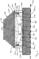
- Fig. 1 shows a simplified cross-sectional view through a press 100 for pressing material 110 according to an embodiment of the present invention.
- the press 100 has at least one roller 120, which is supported on a bearing unit 130 Bracket component 140 is mounted.
- the support member 140 is a fixed axis.
- the roller 120 is part of an assembly referred to as a roller, which also includes the mounting component 140 and the bearing unit 130, among other things.
- the bearing unit 130 which is more closely related to Fig. 2 is arranged and aligned in such a way that the roller 120 is rotatably supported about a rotation line or axis of rotation 150 of the roller 120.
- the rotation line 150 of the roller 120 coincides with an axis of symmetry of the fixed axis (mounting component) 140.
- these can, for example, also have a parallel offset perpendicular to their directions of extension.
- the press 100 also has a die 160, which in the present case is designed as a ring die.
- the ring die 160 is rotatable by one in Fig. 1 Not shown rotation line arranged, which runs parallel to the rotation line 150 of the roller 120. It is driven by a motor that is in Fig. 1 is not shown. In contrast to this, the roller 120 is freely rotatable, that is to say in particular not driven.
- the ring die 160 also has a plurality of openings 170 through which the material 110 is pressed by the roller 120.
- the openings here have a cross section that defines a cross-sectional shape of the pellets 180 produced by the press.
- the press also has one or more optional cutting tools 190 attached to an outside of die 160.
- the die 160 and the roller 120 are in this case designed and spaced such that the material 110 is pressed by the roller 120 through the die 160 when the die is rotated. For this purpose, there is often a preset distance between the die 160 and the roller 120. In other words, the die 160 and the roller 120 are not positively coupled in this arrangement. A rotation of the roller 120 is only brought about by the material 110 filled into the press.
- the distance may also not be present, so that a forced coupling by rolling the roller 120 on the die 160 is effected.
- a forced coupling with an existing or non-existing distance between die 160 and roller 120 can also be realized by a mechanical coupling, for example a gear meshing or a gear. In this way, fixed speed ratios and directions of rotation of the roller 120 and the die 160 relative to one another can also be realized.
- the pellets 180 are cut from the die 160 by one or more optional cutting tools 190. This produces pellets of approximately the same length, while in the absence of the cutting tool (s) 190, the length of the pellets is determined not least by the material properties of the material 110 and the operating parameters of the press (e.g. its rotation speed).
- rollers 120 can also be used in presses according to further exemplary embodiments of the present invention. For example, presses with two, three or more rollers are often used.
- further optional components can be arranged inside the die, such as further support struts or baffles for the material 110.
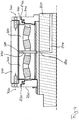
- Fig. 2 shows an enlarged detail of the press 100 Fig.1
- Fig. 2 shows, more specifically, a cross-section through the roller 120, the bearing unit 130 and the fixed axis (holding part) 140 along its rotation or symmetry line 150.
- the bearing unit is - typically by means of a transition fit - applied to the fixed axis (holding component) 140 and secured against axial movement along the axis 140 in a first direction by means of a securing ring 200, for example a snap ring, via a first bearing cover 210.
- a securing ring 200 for example a snap ring
- the bearing unit is secured via a second bearing cover 220 by means of a shaft nut 230 against displacement along the axis 140 in a direction opposite to the first direction.
- the bearing unit can be secured against slipping in the axial direction by other fits and other securing measures, for example by gluing or a tight fit or press fit.
- the bearing unit 130 is also non-positively connected to the roller 120 by means of a tight fit.
- this has a toothing which is designed to interact intensively with the material 110 (not shown in FIG Fig. 2 ) so as to achieve the pressing process between die 160 (not shown in FIG Fig. 2 ) and roller 120 to enable.
- the toothing can, for example, be in the form of a herringbone, semicircular or oblique.
- the roller in a region 250 of the roller 120 lying further inwards, the roller has no special tooth structure or profiling.
- the bearing unit 130 has a double-row tapered roller bearing in an O arrangement, wherein Fig. 2 shows a first rolling element 250 of a first row 260 and a second rolling element 270 of a second row 280.
- the rolling elements 250, 270 are shaped like a truncated cone, as is typical for a tapered roller bearing, and are guided through a first 290 and a second rolling bearing cage 300.
- the pointed sides of the rolling elements 250, 270 face one another (O arrangement).
- the rolling elements of the two rows 260, 280 run in a one-piece outer ring 310 and in a two-piece inner ring 320, which has a first partial inner ring 320-1 and a second partial inner ring 320-2.
- the two partial inner rings 320-1, 320-2 of the inner ring are held together by a fastening device 330 in the form of a perforated metal ring, the holes of which engage in corresponding projections of the two inner rings 320-1, 320-2.
- the fastening device 330 can also be formed by one or more clips or clips.
- the two parts of the inner ring 320 can be connected to one another by another non-positive, positive or material method.
- the exemplary embodiment shown has only the two-part inner ring 320-1, 320-2 ribs for guiding the rolling elements 250, 270, while the common outer ring 310 has no ribs on its running surfaces.
- the storage unit is a self-supporting storage unit that is supplied pre-assembled by the manufacturer before the press 100 is installed and can then be installed as a unit in the press 100 or the wheel rim.
- This makes it possible to set the parameters (for example the internal clearance) of the storage unit 130 separately and in a significantly more controlled and simple manner than if a corresponding setting was only made when the press 100 was assembled.
- it is possible to better adjust the bearing unit 130 to its optimal operating parameters, so that when the press 100 is later operated, it can operate closer to its optimal working point.
- the bearing unit In the area of the perforated metal ring (fastening device 330), the bearing unit has a cavity 340 which can be used, for example, to hold the lubricant reservoir. Before the final assembly of the bearing unit 210, this can be filled with a sufficient amount of a lubricant suitable for the corresponding application, so that safe operation of the bearing unit 210 can be ensured under normal operating conditions for a predetermined operating time (for-life lubrication / lifetime lubrication).
- first 350 and a second sealing element 360 on its sides facing the two bearing caps 220, 230, each in a recess between the inner ring 320 and the outer ring 310 are arranged.
- the exemplary embodiment shown is a cassette seal for grease, each with one, two, three or more radial and axial sealing lips, which seal the bearing unit 130. It can also be optional include other components such as fenders or other elements. Of course, other sealing elements, such as other labyrinth seals or oil seals, can also be used.
- the storage unit 130 as shown in FIG Fig. 2 is shown, two integrated grease seals.
- These sealing units (cassette seals) have an outer jacket made of sheet steel and elastomer. Furthermore, they can have a combination of radial and axial sealing lips as well as integrated mating surfaces and axial sealing lips and axial contact surfaces in various configurations.
- the sealing lips - if they are provided at all - can be implemented with or without tension spring loading.
- One or more protective lips can also be used.
- an integrated bushing for the sealing lip can be used.
- An elastomer seat can optionally also be implemented in the bore and / or on the outer jacket, wherein different elastomer materials can be used for the various elastomer components that may be present.
- a sealing lip loaded with tension spring and three protective lips are used in the frame of the sealing elements.
- the inner construction of the cassette seals can offer the best possible protection against water, dust, mud or other contaminants. It also ensures that the lubricant is safely retained in the bearing.
- the cassette seals can also make the finishing of shafts superfluous.
- the bearing is sealed externally in the form of metallic labyrinth seals or elastomer seals on the roller (also known as a wheel rim or housing).
- the presses are supplied with grease regularly, typically every hour, via automatic central lubrication systems. Due to the high maintenance costs caused by frequent relubrication, it is often not the recommended grease that is used, but a cheaper grease for lubricating the bearing. For economic reasons, the operators of the systems in the food and animal feed sector are tempted not to use food-compatible grease due to the poorer lubricating properties and / or high costs, and thus to run the risk of contamination of the press material, which would contradict legal provisions.
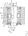
- Fig. 3 shows one Fig. 2 corresponding cross-sectional representation of a conventional bearing arrangement 400.
- the bearing arrangement has a first 410 and a second tapered roller bearing 420, both of which are designed as single-row bearings. In accordance with their single-row design, both have neither a common inner ring nor a common outer ring. Likewise, both are neither self-holding together nor separately.
- an inner ring 430 of the first tapered roller bearing is in contact with a first bearing cover 440, which is mechanically connected to a rigid shaft 470 via a locking ring 450 and a shaft nut 460.
- the screw connection of the shaft nut exerts a force on an outer ring 490 of this tapered roller bearing 410, which is transmitted to a shoulder rim 500 of a roller rim 510.
- the force is transmitted to an outer ring of the second tapered roller bearing 420 via a further shoulder 520 of the wheel rim 510.
- this force is correspondingly transmitted to its inner ring 550 via an outer ring 530 of the second tapered roller bearing 420.
- the force is finally introduced into the rigid axis 470 again via a shoulder 570.
- this flow of force clearly shows that, on the one hand, this conventional bearing arrangement 410 is not self-retaining, so that the bearing arrangement 400 can only be assembled in connection with the final assembly of the press.
- this flow of force also shows that the internal clearance of this bearing arrangement 400 is largely determined by the force exerted via the shaft nut 460. Adjustment can therefore only be carried out as part of the final assembly of the pellet press, since a separate setting to a certain value is impossible due to the lack of self-retaining properties.
- this bearing arrangement 400 will have a less precise adjustment of the bearing clearance, so that the operating point of the pellet press will be less optimal than when using an embodiment of the present invention.
- Fig. 3 a system that requires permanent lubrication or regular relubrication.
- the rigid axle 470 has an opening 580 of a lubricant supply 590, which opens into a cavity 600 between the two tapered roller bearings 410, 420. From there - due to the lack of a seal - the lubricant will pass through the bearings 410, 420 and the two bearing caps 440, 560 into the press chamber.
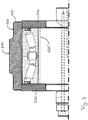
- Fig. 4 shows another of the Fig. 2 Similar representation of a conventional bearing arrangement 700 with a first 710 and a second spherical roller bearing 720.
- the two spherical roller bearings 710, 720 are arranged between a first 730 and a second bearing cover 740, which are screwed to a roller rim 770 of the pellet press via first 750 and second screws 760 ,
- Both spherical roller bearings 710, 720 are in contact with one another in the area of their respective outer rings via a fitting or spacer ring 780, the two bearing caps 730, 740 also being in contact with the outer ring in the assembled state.
- This conventional bearing arrangement 700 is also not self-retaining.
- It also has a cavity 790 in the area of the spacer ring 780 between the two self-aligning bearings 710, 720, into which an opening 800 of a lubricant supply 810 opens in the interior of a standing axis 820.
- Lubricant is supplied to the cavity 790 and thus to the two bearings 710, 720, which can escape into the press chamber via openings 830, 840 in the two bearing caps, so that this bearing arrangement 700 will also contribute to contamination of the material to be pressed by lubricants.
- Fig. 5 shows another of the Fig. 2 Similar cross-sectional view of a conventional bearing assembly 700 ', which differs from the in Fig. 4 differs only slightly, which is why the description of the arrangement Fig. 4 is largely referenced.
- bearing arrangement 700 Fig. 4 stand at the in Fig. 5
- the bearing caps 730, 740 are made in two parts, a part of each cap being in contact with the outer and a part with the respective inner ring of the two adjacent bearings 710, 720.
- both parts are each connected to the wheel rim 770 or the standing axle 820 by means of retaining rings 850, 860.
- a part of the first bearing cover 730 is also connected to the wheel rim 770 via a locking ring 870, while the other part of the first bearing cover 730 is connected to the standing axle 820 via a locking ring 880 and a shaft nut 890.
- This bearing arrangement 700 ' is therefore also not self-retaining
- Fig. 6 shows a cross-sectional view of a bearing unit 130 'according to a further exemplary embodiment of the present invention, which differs from that in FIG Fig. 2 illustrated storage unit 130 in one aspect, so that in addition to the description of that in Fig.2 bearing unit 130 shown.
- the bearing unit 130 In contrast to the one-piece outer ring 310 of the bearing unit 130 Fig. 2 indicates the in Fig. 6 Bearing unit 130 shown on a two-part outer ring 310 with the two parts 310-1 and 310-2, which are assigned to the first tapered roller bearing 260 and the second tapered roller bearing 280 and arranged accordingly.
- the bearing unit 130 ' also has a ring 900 in the region of the end faces of the two parts of the outer ring 130-1, 130-2. This can, for example, with the two parts of the outer ring in sections enter into a positive connection, thus further supporting the self-holding properties.
- the ring 900 can be made from different materials, such as plastic or metal, provided that the material is compatible with the lubricant introduced into the cavity 340.
- FIG. 7 shows a further cross-sectional view through a press 100 according to an exemplary embodiment of the present invention, which differs in terms of storage from that shown in FIG Fig. 6 Storage hardly differs, which is why at this point again on the descriptions of the Figures 6 and 2 is referred.
- the storage unit 130 from Fig. 7 differs from that in Fig. 6 not shown.
- the differences relate to the shape and design of the roller 120 and the two bearing caps 210, 220, apart from structurally determined structures of the holding component 140. While the outer region 240 of the roller hardly differs from the previously described outer regions 240, the inner area 250 at the in Fig. 7 Embodiment shown a significantly lower slope. Rather, this runs essentially parallel to the outer area.
- the exemplary embodiments shown can enable the effects described above.
- a bearing with a precisely defined and reproducible, producible bearing clearance can be created.
- the bearing units 130, 130 'thus have a defined internal clearance and can be sealed and provided with a grease suitable for the application as part of a lifetime lubrication.
- a self-retaining bearing unit 130 generally eliminates the need for maintenance - except in the event of exceptional events and possibly as part of preventive inspections - since these are lubricated for life.
- a central lubrication unit is also no longer required, since the amount of grease and the selection of grease depend on the Application and the service life can be optimized. This means that the operator no longer needs any maintenance and saves time and money.
- the external seal carrier can optionally be omitted, since the seal is integrated in the bearing.
- the sliding seal (sealing elements 350, 360, cassette seals) of the bearing unit 130 in contrast to the previous gap seal, on the one hand enables impurities to not get into the bearing, so that premature bearing failures can be reduced.
- the seal also ensures that the grease essentially does not come out of the storage and the material to be pressed is contaminated.
- a coating of the bearing rings 310, 320 is also provided, or one or more thin intermediate rings are introduced between the bearing rings 310, 320 and the mounting component 140 (fixed axis), which act against "wandering" of the bearing rings 310, 320 in the installed state can fill in the corresponding components with the coating or intermediate ring material by creating the grooves that occur during operation of the press.
- bronze or elastomers can be used as the material for the coating or the intermediate rings.
- the assembly of the bearing units 130 is thus simplified, on the one hand, because of the possibility of fitting intermediate rings, since this replaces a precise adjustment of the individual bearings during the final assembly of the press. In addition, installation errors are largely avoided.
- an exact adjustment of the tapered roller bearings is made possible by the defined, preset axial clearance with little assembly effort. This achieves a more favorable load distribution (distribution of the load over many rolling elements) and extends the service life of the bearings.
- the assembly of the individual components is also dispensed with, since now only a self-supporting bearing unit 130, into which all components can already be integrated, has to be installed.
- the bearing units 130 can also have optional quick assembly devices, for example. These can be a simple one Contact area as well as a more complex structure, such as a coupling or a press fit.
- Bearing units 130 are used in the motor vehicle field, and here in particular in the heavy load force region. These are also referred to as so-called “Truck Hub Units” (THU), but have basic load ratings that cannot actually be used for pellet presses.
- TNU Trust Hub Units
- the present invention is also based on the finding that, due to the much better adaptation of the internal clearance, the loads in the area of roller bearings in presses are lower, as test series and calculations have shown. Although bearing units from the motor vehicle sector cannot actually be used in the press sector due to the low load capacities according to the conventional approach, they can very well be used due to the better adapted internal clearance and the associated reduced fatigue.
- double-row or multi-row, self-holding bearing units are therefore used, in which optionally a defined axial and / or radial bearing clearance is set.
- these can optionally have a common outer and / or inner ring. They can also be optionally equipped with an integrated seal.
- they can also be filled with lubricant.
- a coating of the rolling element raceways and / or bearing ring surfaces is also possible.
- the storage units can also optionally have a quick assembly device, for. B. a hydraulically or electrically generated press fit or a correspondingly generated coupling.
Landscapes
- Engineering & Computer Science (AREA)
- General Engineering & Computer Science (AREA)
- Mechanical Engineering (AREA)
- Rolling Contact Bearings (AREA)
Priority Applications (1)
| Application Number | Priority Date | Filing Date | Title |
|---|---|---|---|
| PL11791515T PL2648899T3 (pl) | 2010-12-06 | 2011-11-29 | Prasa do prasowania materiału |
Applications Claiming Priority (2)
| Application Number | Priority Date | Filing Date | Title |
|---|---|---|---|
| DE102010062477A DE102010062477B4 (de) | 2010-12-06 | 2010-12-06 | Presse zum Pressen eines Materials |
| PCT/EP2011/071256 WO2012076361A1 (de) | 2010-12-06 | 2011-11-29 | Presse zum pressen eines materials |
Publications (2)
| Publication Number | Publication Date |
|---|---|
| EP2648899A1 EP2648899A1 (de) | 2013-10-16 |
| EP2648899B1 true EP2648899B1 (de) | 2020-01-08 |
Family
ID=45099073
Family Applications (1)
| Application Number | Title | Priority Date | Filing Date |
|---|---|---|---|
| EP11791515.7A Active EP2648899B1 (de) | 2010-12-06 | 2011-11-29 | Presse zum pressen eines materials |
Country Status (5)
| Country | Link |
|---|---|
| EP (1) | EP2648899B1 (pl) |
| DE (1) | DE102010062477B4 (pl) |
| ES (1) | ES2774255T3 (pl) |
| PL (1) | PL2648899T3 (pl) |
| WO (1) | WO2012076361A1 (pl) |
Cited By (1)
| Publication number | Priority date | Publication date | Assignee | Title |
|---|---|---|---|---|
| EP4186684A1 (de) * | 2021-11-29 | 2023-05-31 | Salzhausener Maschinenbautechnik SALMATEC GmbH | Automatische einstellvorrichtung für koller einer pelletierpresse |
Families Citing this family (1)
| Publication number | Priority date | Publication date | Assignee | Title |
|---|---|---|---|---|
| DE102021102833A1 (de) * | 2021-02-08 | 2022-08-11 | Aktiebolaget Skf | Schneidringanordnung |
Citations (1)
| Publication number | Priority date | Publication date | Assignee | Title |
|---|---|---|---|---|
| FR2747747A1 (fr) * | 1996-04-18 | 1997-10-24 | Luxor Sarl | Galet de pressage pour presse a granuler et presse a granuler equipee de tels galets |
Family Cites Families (10)
| Publication number | Priority date | Publication date | Assignee | Title |
|---|---|---|---|---|
| GB526890A (en) * | 1939-03-21 | 1940-09-27 | John Hansford Thompson | Apparatus for forming nodules and the like |
| US2700940A (en) * | 1948-04-02 | 1955-02-01 | Clyde V Johnson | Apparatus for preparing moldable materials and producing pellets |
| US4235485A (en) * | 1978-12-21 | 1980-11-25 | The Timken Company | Unitized multirow tapered roller bearing |
| US4770424A (en) * | 1985-12-19 | 1988-09-13 | The Timken Company | Compact labyrinth-type seal |
| AU5348298A (en) * | 1997-12-17 | 1999-07-05 | Skf Engineering & Research Centre B.V. | Angular contact bearing unit with one piece inner bearing element |
| DE112007001017B4 (de) * | 2006-04-25 | 2016-10-27 | Ntn Corporation | Radlagervorrichtung |
| CN201189726Y (zh) * | 2008-04-14 | 2009-02-04 | 江苏牧羊集团有限公司 | 一种环模制粒机的润滑系统 |
| DE102008038543A1 (de) * | 2008-08-20 | 2010-02-25 | Eduard Schwarz | Verhinderung des Eindringens von Schmutzpartikeln in Lagergehäuse |
| US20100183759A1 (en) | 2009-01-21 | 2010-07-22 | Allis Carl R | Roller for Pelleting Mill |
| CN201552771U (zh) * | 2009-12-11 | 2010-08-18 | 中国科学院广州能源研究所 | 一种生物质成型燃料设备的压辊结构 |
-
2010
- 2010-12-06 DE DE102010062477A patent/DE102010062477B4/de active Active
-
2011
- 2011-11-29 EP EP11791515.7A patent/EP2648899B1/de active Active
- 2011-11-29 WO PCT/EP2011/071256 patent/WO2012076361A1/de not_active Ceased
- 2011-11-29 PL PL11791515T patent/PL2648899T3/pl unknown
- 2011-11-29 ES ES11791515T patent/ES2774255T3/es active Active
Patent Citations (1)
| Publication number | Priority date | Publication date | Assignee | Title |
|---|---|---|---|---|
| FR2747747A1 (fr) * | 1996-04-18 | 1997-10-24 | Luxor Sarl | Galet de pressage pour presse a granuler et presse a granuler equipee de tels galets |
Cited By (1)
| Publication number | Priority date | Publication date | Assignee | Title |
|---|---|---|---|---|
| EP4186684A1 (de) * | 2021-11-29 | 2023-05-31 | Salzhausener Maschinenbautechnik SALMATEC GmbH | Automatische einstellvorrichtung für koller einer pelletierpresse |
Also Published As
| Publication number | Publication date |
|---|---|
| DE102010062477B4 (de) | 2013-04-11 |
| WO2012076361A1 (de) | 2012-06-14 |
| EP2648899A1 (de) | 2013-10-16 |
| ES2774255T3 (es) | 2020-07-20 |
| DE102010062477A1 (de) | 2012-06-06 |
| PL2648899T3 (pl) | 2020-06-29 |
Similar Documents
| Publication | Publication Date | Title |
|---|---|---|
| DE10235239B4 (de) | Schmierfett-geschmiertes Schrägkugellager und Spindelvorrichtung für Werkzeugmaschinen | |
| DE60316139T2 (de) | Ritzelwelle mit entsprechend abstützender Lagervorrichtung | |
| EP2233760B1 (de) | Fettgeschmiertes zweireihiges Wälzlager und Lagersystem mit einem derartigen Wälzlager und einer Schmiereinrichtung | |
| DE3886850T2 (de) | Dichtung. | |
| EP2561241B1 (de) | Dichtungsanordnung für wälzlager | |
| DE69527230T2 (de) | Lager | |
| EP2126386A1 (de) | Lageranordnung | |
| DE10045163B4 (de) | Wellenlagerungsanordung | |
| DE102020001269A1 (de) | Getriebe und Verfahren zum Herstellen unterschiedlicher Getriebe, insbesondere einer Getriebebaureihe | |
| DE102016214350A1 (de) | Verfahren und Vorrichtung zur Herstellung eines Schrägrollenlagers | |
| DE102010000809B4 (de) | Kompakte Axial-Radial-Lagerung | |
| DE102019201552A1 (de) | Lagerung eines Planetenrades auf einem mit einem Planetenträger verbundenen Planetenbolzen und Verfahren zur Montage eines Planetenrades auf einem Planetenbolzen | |
| EP2648899B1 (de) | Presse zum pressen eines materials | |
| DE102004019974B4 (de) | Achslager des Schienenfahrzeuges | |
| DE102019200398A1 (de) | Selbst-ausrichtendes Rollenlager | |
| EP2358931B1 (de) | Oberwalze für ein streckwerk | |
| EP3472482B1 (de) | Gelenkanordnung für eine gelenkwelle | |
| DE102022113004B4 (de) | Wälzlagervorrichtung | |
| DE102021104853B3 (de) | Radsatzlager für ein Schienenfahrzeug | |
| DE102023000505A1 (de) | Getriebe mit Gehäuseteil und Lager zur drehbaren Lagerung einer Welle | |
| DE102016211194A1 (de) | Werkzeug zum Einpressen eines Lagers | |
| DE102006004749B4 (de) | Axial-Schrägnadellager | |
| DE102005011963B4 (de) | Lageranordnung | |
| DE202015009197U1 (de) | Lageranordnung zwischen einer Achsbrücke und einem Antriebskasten | |
| DE102020121938B4 (de) | Lageranordnung mit einem Axiallager mit einer Axiallagerscheibe |
Legal Events
| Date | Code | Title | Description |
|---|---|---|---|
| PUAI | Public reference made under article 153(3) epc to a published international application that has entered the european phase |
Free format text: ORIGINAL CODE: 0009012 |
|
| 17P | Request for examination filed |
Effective date: 20130607 |
|
| AK | Designated contracting states |
Kind code of ref document: A1 Designated state(s): AL AT BE BG CH CY CZ DE DK EE ES FI FR GB GR HR HU IE IS IT LI LT LU LV MC MK MT NL NO PL PT RO RS SE SI SK SM TR |
|
| DAX | Request for extension of the european patent (deleted) | ||
| STAA | Information on the status of an ep patent application or granted ep patent |
Free format text: STATUS: EXAMINATION IS IN PROGRESS |
|
| 17Q | First examination report despatched |
Effective date: 20171220 |
|
| GRAP | Despatch of communication of intention to grant a patent |
Free format text: ORIGINAL CODE: EPIDOSNIGR1 |
|
| STAA | Information on the status of an ep patent application or granted ep patent |
Free format text: STATUS: GRANT OF PATENT IS INTENDED |
|
| INTG | Intention to grant announced |
Effective date: 20190628 |
|
| GRAS | Grant fee paid |
Free format text: ORIGINAL CODE: EPIDOSNIGR3 |
|
| GRAA | (expected) grant |
Free format text: ORIGINAL CODE: 0009210 |
|
| STAA | Information on the status of an ep patent application or granted ep patent |
Free format text: STATUS: THE PATENT HAS BEEN GRANTED |
|
| AK | Designated contracting states |
Kind code of ref document: B1 Designated state(s): AL AT BE BG CH CY CZ DE DK EE ES FI FR GB GR HR HU IE IS IT LI LT LU LV MC MK MT NL NO PL PT RO RS SE SI SK SM TR |
|
| REG | Reference to a national code |
Ref country code: GB Ref legal event code: FG4D Free format text: NOT ENGLISH |
|
| REG | Reference to a national code |
Ref country code: CH Ref legal event code: EP |
|
| REG | Reference to a national code |
Ref country code: DE Ref legal event code: R096 Ref document number: 502011016389 Country of ref document: DE |
|
| REG | Reference to a national code |
Ref country code: IE Ref legal event code: FG4D Free format text: LANGUAGE OF EP DOCUMENT: GERMAN |
|
| REG | Reference to a national code |
Ref country code: AT Ref legal event code: REF Ref document number: 1222171 Country of ref document: AT Kind code of ref document: T Effective date: 20200215 |
|
| REG | Reference to a national code |
Ref country code: NL Ref legal event code: FP |
|
| REG | Reference to a national code |
Ref country code: SE Ref legal event code: TRGR |
|
| REG | Reference to a national code |
Ref country code: LT Ref legal event code: MG4D |
|
| REG | Reference to a national code |
Ref country code: ES Ref legal event code: FG2A Ref document number: 2774255 Country of ref document: ES Kind code of ref document: T3 Effective date: 20200720 |
|
| PG25 | Lapsed in a contracting state [announced via postgrant information from national office to epo] |
Ref country code: RS Free format text: LAPSE BECAUSE OF FAILURE TO SUBMIT A TRANSLATION OF THE DESCRIPTION OR TO PAY THE FEE WITHIN THE PRESCRIBED TIME-LIMIT Effective date: 20200108 Ref country code: LT Free format text: LAPSE BECAUSE OF FAILURE TO SUBMIT A TRANSLATION OF THE DESCRIPTION OR TO PAY THE FEE WITHIN THE PRESCRIBED TIME-LIMIT Effective date: 20200108 Ref country code: NO Free format text: LAPSE BECAUSE OF FAILURE TO SUBMIT A TRANSLATION OF THE DESCRIPTION OR TO PAY THE FEE WITHIN THE PRESCRIBED TIME-LIMIT Effective date: 20200408 Ref country code: FI Free format text: LAPSE BECAUSE OF FAILURE TO SUBMIT A TRANSLATION OF THE DESCRIPTION OR TO PAY THE FEE WITHIN THE PRESCRIBED TIME-LIMIT Effective date: 20200108 Ref country code: PT Free format text: LAPSE BECAUSE OF FAILURE TO SUBMIT A TRANSLATION OF THE DESCRIPTION OR TO PAY THE FEE WITHIN THE PRESCRIBED TIME-LIMIT Effective date: 20200531 |
|
| PG25 | Lapsed in a contracting state [announced via postgrant information from national office to epo] |
Ref country code: LV Free format text: LAPSE BECAUSE OF FAILURE TO SUBMIT A TRANSLATION OF THE DESCRIPTION OR TO PAY THE FEE WITHIN THE PRESCRIBED TIME-LIMIT Effective date: 20200108 Ref country code: HR Free format text: LAPSE BECAUSE OF FAILURE TO SUBMIT A TRANSLATION OF THE DESCRIPTION OR TO PAY THE FEE WITHIN THE PRESCRIBED TIME-LIMIT Effective date: 20200108 Ref country code: GR Free format text: LAPSE BECAUSE OF FAILURE TO SUBMIT A TRANSLATION OF THE DESCRIPTION OR TO PAY THE FEE WITHIN THE PRESCRIBED TIME-LIMIT Effective date: 20200409 Ref country code: IS Free format text: LAPSE BECAUSE OF FAILURE TO SUBMIT A TRANSLATION OF THE DESCRIPTION OR TO PAY THE FEE WITHIN THE PRESCRIBED TIME-LIMIT Effective date: 20200508 Ref country code: BG Free format text: LAPSE BECAUSE OF FAILURE TO SUBMIT A TRANSLATION OF THE DESCRIPTION OR TO PAY THE FEE WITHIN THE PRESCRIBED TIME-LIMIT Effective date: 20200408 |
|
| REG | Reference to a national code |
Ref country code: DE Ref legal event code: R097 Ref document number: 502011016389 Country of ref document: DE |
|
| PG25 | Lapsed in a contracting state [announced via postgrant information from national office to epo] |
Ref country code: SK Free format text: LAPSE BECAUSE OF FAILURE TO SUBMIT A TRANSLATION OF THE DESCRIPTION OR TO PAY THE FEE WITHIN THE PRESCRIBED TIME-LIMIT Effective date: 20200108 Ref country code: RO Free format text: LAPSE BECAUSE OF FAILURE TO SUBMIT A TRANSLATION OF THE DESCRIPTION OR TO PAY THE FEE WITHIN THE PRESCRIBED TIME-LIMIT Effective date: 20200108 Ref country code: CZ Free format text: LAPSE BECAUSE OF FAILURE TO SUBMIT A TRANSLATION OF THE DESCRIPTION OR TO PAY THE FEE WITHIN THE PRESCRIBED TIME-LIMIT Effective date: 20200108 Ref country code: EE Free format text: LAPSE BECAUSE OF FAILURE TO SUBMIT A TRANSLATION OF THE DESCRIPTION OR TO PAY THE FEE WITHIN THE PRESCRIBED TIME-LIMIT Effective date: 20200108 Ref country code: SM Free format text: LAPSE BECAUSE OF FAILURE TO SUBMIT A TRANSLATION OF THE DESCRIPTION OR TO PAY THE FEE WITHIN THE PRESCRIBED TIME-LIMIT Effective date: 20200108 Ref country code: DK Free format text: LAPSE BECAUSE OF FAILURE TO SUBMIT A TRANSLATION OF THE DESCRIPTION OR TO PAY THE FEE WITHIN THE PRESCRIBED TIME-LIMIT Effective date: 20200108 |
|
| PLBE | No opposition filed within time limit |
Free format text: ORIGINAL CODE: 0009261 |
|
| STAA | Information on the status of an ep patent application or granted ep patent |
Free format text: STATUS: NO OPPOSITION FILED WITHIN TIME LIMIT |
|
| 26N | No opposition filed |
Effective date: 20201009 |
|
| PG25 | Lapsed in a contracting state [announced via postgrant information from national office to epo] |
Ref country code: SI Free format text: LAPSE BECAUSE OF FAILURE TO SUBMIT A TRANSLATION OF THE DESCRIPTION OR TO PAY THE FEE WITHIN THE PRESCRIBED TIME-LIMIT Effective date: 20200108 |
|
| PG25 | Lapsed in a contracting state [announced via postgrant information from national office to epo] |
Ref country code: MC Free format text: LAPSE BECAUSE OF FAILURE TO SUBMIT A TRANSLATION OF THE DESCRIPTION OR TO PAY THE FEE WITHIN THE PRESCRIBED TIME-LIMIT Effective date: 20200108 |
|
| GBPC | Gb: european patent ceased through non-payment of renewal fee |
Effective date: 20201129 |
|
| PG25 | Lapsed in a contracting state [announced via postgrant information from national office to epo] |
Ref country code: LU Free format text: LAPSE BECAUSE OF NON-PAYMENT OF DUE FEES Effective date: 20201129 |
|
| REG | Reference to a national code |
Ref country code: BE Ref legal event code: MM Effective date: 20201130 |
|
| REG | Reference to a national code |
Ref country code: IE Ref legal event code: MM4A |
|
| PG25 | Lapsed in a contracting state [announced via postgrant information from national office to epo] |
Ref country code: IE Free format text: LAPSE BECAUSE OF NON-PAYMENT OF DUE FEES Effective date: 20201129 |
|
| PG25 | Lapsed in a contracting state [announced via postgrant information from national office to epo] |
Ref country code: GB Free format text: LAPSE BECAUSE OF NON-PAYMENT OF DUE FEES Effective date: 20201129 |
|
| PG25 | Lapsed in a contracting state [announced via postgrant information from national office to epo] |
Ref country code: TR Free format text: LAPSE BECAUSE OF FAILURE TO SUBMIT A TRANSLATION OF THE DESCRIPTION OR TO PAY THE FEE WITHIN THE PRESCRIBED TIME-LIMIT Effective date: 20200108 Ref country code: MT Free format text: LAPSE BECAUSE OF FAILURE TO SUBMIT A TRANSLATION OF THE DESCRIPTION OR TO PAY THE FEE WITHIN THE PRESCRIBED TIME-LIMIT Effective date: 20200108 Ref country code: CY Free format text: LAPSE BECAUSE OF FAILURE TO SUBMIT A TRANSLATION OF THE DESCRIPTION OR TO PAY THE FEE WITHIN THE PRESCRIBED TIME-LIMIT Effective date: 20200108 |
|
| PG25 | Lapsed in a contracting state [announced via postgrant information from national office to epo] |
Ref country code: MK Free format text: LAPSE BECAUSE OF FAILURE TO SUBMIT A TRANSLATION OF THE DESCRIPTION OR TO PAY THE FEE WITHIN THE PRESCRIBED TIME-LIMIT Effective date: 20200108 Ref country code: AL Free format text: LAPSE BECAUSE OF FAILURE TO SUBMIT A TRANSLATION OF THE DESCRIPTION OR TO PAY THE FEE WITHIN THE PRESCRIBED TIME-LIMIT Effective date: 20200108 |
|
| PG25 | Lapsed in a contracting state [announced via postgrant information from national office to epo] |
Ref country code: BE Free format text: LAPSE BECAUSE OF NON-PAYMENT OF DUE FEES Effective date: 20201130 |
|
| P01 | Opt-out of the competence of the unified patent court (upc) registered |
Effective date: 20230513 |
|
| REG | Reference to a national code |
Ref country code: CH Ref legal event code: U11 Free format text: ST27 STATUS EVENT CODE: U-0-0-U10-U11 (AS PROVIDED BY THE NATIONAL OFFICE) Effective date: 20251201 |
|
| PGFP | Annual fee paid to national office [announced via postgrant information from national office to epo] |
Ref country code: NL Payment date: 20251124 Year of fee payment: 15 |
|
| PGFP | Annual fee paid to national office [announced via postgrant information from national office to epo] |
Ref country code: DE Payment date: 20251126 Year of fee payment: 15 |
|
| PGFP | Annual fee paid to national office [announced via postgrant information from national office to epo] |
Ref country code: AT Payment date: 20251118 Year of fee payment: 15 |
|
| PGFP | Annual fee paid to national office [announced via postgrant information from national office to epo] |
Ref country code: IT Payment date: 20251121 Year of fee payment: 15 |
|
| PGFP | Annual fee paid to national office [announced via postgrant information from national office to epo] |
Ref country code: FR Payment date: 20251124 Year of fee payment: 15 |
|
| PGFP | Annual fee paid to national office [announced via postgrant information from national office to epo] |
Ref country code: SE Payment date: 20251124 Year of fee payment: 15 Ref country code: CH Payment date: 20251201 Year of fee payment: 15 |
|
| PGFP | Annual fee paid to national office [announced via postgrant information from national office to epo] |
Ref country code: PL Payment date: 20251126 Year of fee payment: 15 |
|
| PGFP | Annual fee paid to national office [announced via postgrant information from national office to epo] |
Ref country code: ES Payment date: 20251209 Year of fee payment: 15 |