EP2648899B1 - Press for pressing a material - Google Patents
Press for pressing a material Download PDFInfo
- Publication number
- EP2648899B1 EP2648899B1 EP11791515.7A EP11791515A EP2648899B1 EP 2648899 B1 EP2648899 B1 EP 2648899B1 EP 11791515 A EP11791515 A EP 11791515A EP 2648899 B1 EP2648899 B1 EP 2648899B1
- Authority
- EP
- European Patent Office
- Prior art keywords
- bearing unit
- press
- bearing
- roller
- lubricant
- Prior art date
- Legal status (The legal status is an assumption and is not a legal conclusion. Google has not performed a legal analysis and makes no representation as to the accuracy of the status listed.)
- Active
Links
- 239000000463 material Substances 0.000 title claims description 36
- 238000003825 pressing Methods 0.000 title claims description 10
- 239000000314 lubricant Substances 0.000 claims description 32
- 238000007789 sealing Methods 0.000 claims description 22
- 239000008188 pellet Substances 0.000 claims description 18
- 239000011248 coating agent Substances 0.000 claims description 10
- 238000000576 coating method Methods 0.000 claims description 10
- 229920001971 elastomer Polymers 0.000 claims description 8
- 239000000806 elastomer Substances 0.000 claims description 8
- 238000005461 lubrication Methods 0.000 claims description 7
- 239000000356 contaminant Substances 0.000 claims description 6
- 229910000906 Bronze Inorganic materials 0.000 claims description 3
- 239000010974 bronze Substances 0.000 claims description 3
- KUNSUQLRTQLHQQ-UHFFFAOYSA-N copper tin Chemical compound [Cu].[Sn] KUNSUQLRTQLHQQ-UHFFFAOYSA-N 0.000 claims description 3
- 239000002023 wood Substances 0.000 claims description 2
- 230000035515 penetration Effects 0.000 claims 2
- 238000003860 storage Methods 0.000 description 19
- 238000005096 rolling process Methods 0.000 description 16
- 239000004519 grease Substances 0.000 description 13
- 238000011109 contamination Methods 0.000 description 6
- 238000012423 maintenance Methods 0.000 description 6
- 230000008878 coupling Effects 0.000 description 5
- 238000010168 coupling process Methods 0.000 description 5
- 238000005859 coupling reaction Methods 0.000 description 5
- 230000000052 comparative effect Effects 0.000 description 4
- 238000005520 cutting process Methods 0.000 description 4
- 238000013461 design Methods 0.000 description 4
- 239000002184 metal Substances 0.000 description 4
- 229910052751 metal Inorganic materials 0.000 description 4
- 238000005453 pelletization Methods 0.000 description 4
- 125000006850 spacer group Chemical group 0.000 description 4
- 230000001050 lubricating effect Effects 0.000 description 3
- 230000036961 partial effect Effects 0.000 description 3
- 239000004033 plastic Substances 0.000 description 3
- 230000001681 protective effect Effects 0.000 description 3
- 241001465754 Metazoa Species 0.000 description 2
- 238000009826 distribution Methods 0.000 description 2
- 239000000428 dust Substances 0.000 description 2
- 238000000034 method Methods 0.000 description 2
- 239000003921 oil Substances 0.000 description 2
- 239000002245 particle Substances 0.000 description 2
- 230000002829 reductive effect Effects 0.000 description 2
- 229910000831 Steel Inorganic materials 0.000 description 1
- 230000006978 adaptation Effects 0.000 description 1
- 238000004026 adhesive bonding Methods 0.000 description 1
- 238000013459 approach Methods 0.000 description 1
- 239000000969 carrier Substances 0.000 description 1
- 238000010276 construction Methods 0.000 description 1
- 235000015872 dietary supplement Nutrition 0.000 description 1
- 238000006073 displacement reaction Methods 0.000 description 1
- 230000000694 effects Effects 0.000 description 1
- 230000002349 favourable effect Effects 0.000 description 1
- 239000012535 impurity Substances 0.000 description 1
- 238000007689 inspection Methods 0.000 description 1
- 238000009434 installation Methods 0.000 description 1
- 239000011499 joint compound Substances 0.000 description 1
- 238000004519 manufacturing process Methods 0.000 description 1
- 230000013011 mating Effects 0.000 description 1
- 230000036316 preload Effects 0.000 description 1
- 230000002028 premature Effects 0.000 description 1
- 230000003449 preventive effect Effects 0.000 description 1
- 238000012545 processing Methods 0.000 description 1
- 230000000717 retained effect Effects 0.000 description 1
- 238000007493 shaping process Methods 0.000 description 1
- 230000035939 shock Effects 0.000 description 1
- 239000007787 solid Substances 0.000 description 1
- 239000007858 starting material Substances 0.000 description 1
- 239000010959 steel Substances 0.000 description 1
- 238000012360 testing method Methods 0.000 description 1
- 230000007704 transition Effects 0.000 description 1
- UONOETXJSWQNOL-UHFFFAOYSA-N tungsten carbide Chemical compound [W+]#[C-] UONOETXJSWQNOL-UHFFFAOYSA-N 0.000 description 1
- XLYOFNOQVPJJNP-UHFFFAOYSA-N water Substances O XLYOFNOQVPJJNP-UHFFFAOYSA-N 0.000 description 1
Images


Classifications
-
- B—PERFORMING OPERATIONS; TRANSPORTING
- B30—PRESSES
- B30B—PRESSES IN GENERAL
- B30B11/00—Presses specially adapted for forming shaped articles from material in particulate or plastic state, e.g. briquetting presses, tabletting presses
- B30B11/20—Roller-and-ring machines, i.e. with roller disposed within a ring and co-operating with the inner surface of the ring
- B30B11/201—Roller-and-ring machines, i.e. with roller disposed within a ring and co-operating with the inner surface of the ring for extruding material
- B30B11/208—Roller constructions; Mounting of the rollers
-
- F—MECHANICAL ENGINEERING; LIGHTING; HEATING; WEAPONS; BLASTING
- F16—ENGINEERING ELEMENTS AND UNITS; GENERAL MEASURES FOR PRODUCING AND MAINTAINING EFFECTIVE FUNCTIONING OF MACHINES OR INSTALLATIONS; THERMAL INSULATION IN GENERAL
- F16C—SHAFTS; FLEXIBLE SHAFTS; ELEMENTS OR CRANKSHAFT MECHANISMS; ROTARY BODIES OTHER THAN GEARING ELEMENTS; BEARINGS
- F16C13/00—Rolls, drums, discs, or the like; Bearings or mountings therefor
- F16C13/02—Bearings
-
- F—MECHANICAL ENGINEERING; LIGHTING; HEATING; WEAPONS; BLASTING
- F16—ENGINEERING ELEMENTS AND UNITS; GENERAL MEASURES FOR PRODUCING AND MAINTAINING EFFECTIVE FUNCTIONING OF MACHINES OR INSTALLATIONS; THERMAL INSULATION IN GENERAL
- F16C—SHAFTS; FLEXIBLE SHAFTS; ELEMENTS OR CRANKSHAFT MECHANISMS; ROTARY BODIES OTHER THAN GEARING ELEMENTS; BEARINGS
- F16C19/00—Bearings with rolling contact, for exclusively rotary movement
- F16C19/22—Bearings with rolling contact, for exclusively rotary movement with bearing rollers essentially of the same size in one or more circular rows, e.g. needle bearings
- F16C19/34—Bearings with rolling contact, for exclusively rotary movement with bearing rollers essentially of the same size in one or more circular rows, e.g. needle bearings for both radial and axial load
- F16C19/38—Bearings with rolling contact, for exclusively rotary movement with bearing rollers essentially of the same size in one or more circular rows, e.g. needle bearings for both radial and axial load with two or more rows of rollers
- F16C19/383—Bearings with rolling contact, for exclusively rotary movement with bearing rollers essentially of the same size in one or more circular rows, e.g. needle bearings for both radial and axial load with two or more rows of rollers with tapered rollers, i.e. rollers having essentially the shape of a truncated cone
- F16C19/385—Bearings with rolling contact, for exclusively rotary movement with bearing rollers essentially of the same size in one or more circular rows, e.g. needle bearings for both radial and axial load with two or more rows of rollers with tapered rollers, i.e. rollers having essentially the shape of a truncated cone with two rows, i.e. double-row tapered roller bearings
- F16C19/386—Bearings with rolling contact, for exclusively rotary movement with bearing rollers essentially of the same size in one or more circular rows, e.g. needle bearings for both radial and axial load with two or more rows of rollers with tapered rollers, i.e. rollers having essentially the shape of a truncated cone with two rows, i.e. double-row tapered roller bearings in O-arrangement
-
- F—MECHANICAL ENGINEERING; LIGHTING; HEATING; WEAPONS; BLASTING
- F16—ENGINEERING ELEMENTS AND UNITS; GENERAL MEASURES FOR PRODUCING AND MAINTAINING EFFECTIVE FUNCTIONING OF MACHINES OR INSTALLATIONS; THERMAL INSULATION IN GENERAL
- F16C—SHAFTS; FLEXIBLE SHAFTS; ELEMENTS OR CRANKSHAFT MECHANISMS; ROTARY BODIES OTHER THAN GEARING ELEMENTS; BEARINGS
- F16C19/00—Bearings with rolling contact, for exclusively rotary movement
- F16C19/54—Systems consisting of a plurality of bearings with rolling friction
- F16C19/541—Systems consisting of juxtaposed rolling bearings including at least one angular contact bearing
- F16C19/542—Systems consisting of juxtaposed rolling bearings including at least one angular contact bearing with two rolling bearings with angular contact
- F16C19/543—Systems consisting of juxtaposed rolling bearings including at least one angular contact bearing with two rolling bearings with angular contact in O-arrangement
-
- F—MECHANICAL ENGINEERING; LIGHTING; HEATING; WEAPONS; BLASTING
- F16—ENGINEERING ELEMENTS AND UNITS; GENERAL MEASURES FOR PRODUCING AND MAINTAINING EFFECTIVE FUNCTIONING OF MACHINES OR INSTALLATIONS; THERMAL INSULATION IN GENERAL
- F16C—SHAFTS; FLEXIBLE SHAFTS; ELEMENTS OR CRANKSHAFT MECHANISMS; ROTARY BODIES OTHER THAN GEARING ELEMENTS; BEARINGS
- F16C19/00—Bearings with rolling contact, for exclusively rotary movement
- F16C19/22—Bearings with rolling contact, for exclusively rotary movement with bearing rollers essentially of the same size in one or more circular rows, e.g. needle bearings
- F16C19/34—Bearings with rolling contact, for exclusively rotary movement with bearing rollers essentially of the same size in one or more circular rows, e.g. needle bearings for both radial and axial load
- F16C19/38—Bearings with rolling contact, for exclusively rotary movement with bearing rollers essentially of the same size in one or more circular rows, e.g. needle bearings for both radial and axial load with two or more rows of rollers
-
- F—MECHANICAL ENGINEERING; LIGHTING; HEATING; WEAPONS; BLASTING
- F16—ENGINEERING ELEMENTS AND UNITS; GENERAL MEASURES FOR PRODUCING AND MAINTAINING EFFECTIVE FUNCTIONING OF MACHINES OR INSTALLATIONS; THERMAL INSULATION IN GENERAL
- F16C—SHAFTS; FLEXIBLE SHAFTS; ELEMENTS OR CRANKSHAFT MECHANISMS; ROTARY BODIES OTHER THAN GEARING ELEMENTS; BEARINGS
- F16C19/00—Bearings with rolling contact, for exclusively rotary movement
- F16C19/54—Systems consisting of a plurality of bearings with rolling friction
- F16C19/541—Systems consisting of juxtaposed rolling bearings including at least one angular contact bearing
- F16C19/542—Systems consisting of juxtaposed rolling bearings including at least one angular contact bearing with two rolling bearings with angular contact
-
- F—MECHANICAL ENGINEERING; LIGHTING; HEATING; WEAPONS; BLASTING
- F16—ENGINEERING ELEMENTS AND UNITS; GENERAL MEASURES FOR PRODUCING AND MAINTAINING EFFECTIVE FUNCTIONING OF MACHINES OR INSTALLATIONS; THERMAL INSULATION IN GENERAL
- F16C—SHAFTS; FLEXIBLE SHAFTS; ELEMENTS OR CRANKSHAFT MECHANISMS; ROTARY BODIES OTHER THAN GEARING ELEMENTS; BEARINGS
- F16C19/00—Bearings with rolling contact, for exclusively rotary movement
- F16C19/54—Systems consisting of a plurality of bearings with rolling friction
- F16C19/546—Systems with spaced apart rolling bearings including at least one angular contact bearing
- F16C19/547—Systems with spaced apart rolling bearings including at least one angular contact bearing with two angular contact rolling bearings
-
- F—MECHANICAL ENGINEERING; LIGHTING; HEATING; WEAPONS; BLASTING
- F16—ENGINEERING ELEMENTS AND UNITS; GENERAL MEASURES FOR PRODUCING AND MAINTAINING EFFECTIVE FUNCTIONING OF MACHINES OR INSTALLATIONS; THERMAL INSULATION IN GENERAL
- F16C—SHAFTS; FLEXIBLE SHAFTS; ELEMENTS OR CRANKSHAFT MECHANISMS; ROTARY BODIES OTHER THAN GEARING ELEMENTS; BEARINGS
- F16C23/00—Bearings for exclusively rotary movement adjustable for aligning or positioning
- F16C23/06—Ball or roller bearings
- F16C23/08—Ball or roller bearings self-adjusting
- F16C23/082—Ball or roller bearings self-adjusting by means of at least one substantially spherical surface
- F16C23/086—Ball or roller bearings self-adjusting by means of at least one substantially spherical surface forming a track for rolling elements
Definitions
- Embodiments of the present invention relate to presses for pressing a material, for example pelletizing plants or pellet presses, as can be used in the woodworking industry or in the food, food supplement or concentrated feed industry.
- pellets Many materials are sold for further processing or consumption in the form of small pressed bodies, so-called pellets.
- the starting material is often produced in a spherical or cylindrical, compressed form by pressing in so-called pelletizing plants or presses.
- pelletizing plants or presses For example, wood or concentrated feed for fattening and / or feeding farm animals is sold in pellet form.
- Pelletizing plants generally comprise one or more mills that press the material to be processed into pellets on a ring or flat die.
- the koller includes the actual koller rim (roller), but also the bearing cap, the bearings and the axle.
- the rollers are supported with two individual bearings, which are tapered roller bearings or spherical roller bearings. Employment is indispensable for storage with conventional tapered roller bearings, which requires a great deal of effort and experience during assembly. A collective, and thus accidental employment of all tapered roller bearings can only take place if the operating conditions allow it d. H. no high demands are placed on the storage.
- pelleting systems Due to the high loads and shocks to which the rollers are exposed during operation, pelleting systems place high demands on storage. For this reason, the assembly should be carried out as accurately as possible. In reality it will however - not least for cost reasons - the job was made inaccurately in order to make the assembly easier and therefore more cost-effective. Pelleting systems are therefore often not operated in the area of their maximum performance or in the area of increased wear.
- the materials used often pose a high risk of contamination for the bearings.
- the ambient conditions accordingly have a very high degree of contamination, so that relubrication must be carried out regularly, for example every hour, in order to push the penetrated contamination particles out of the bearings again.
- the maintenance effort and costs for the operator are enormous.
- the US 2010/0183759 A1 describes, for example, a roller for a pelletizing system, which has two spherical roller bearings for storing the roller and a seal.
- the DE 10 2008 O38 543 A1 describes a device for preventing the ingress of dirt and dust particles in bearing housings, particularly in the case of press rolls, in which an axis is carried out and whose bearings are sealed with a protective ring.
- GB 526,890 teaches a machine for shaping pellets, tubers etc., which comprises a rotatable cylindrical shape with openings and rollers which successively press the material supplied to the cylinder against the inner surface and push it through the openings, so that the shaped bodies can be removed by a scraper.
- FR 2 747 747 teaches a roller to press a material through a granulating press that has a plastic shell.
- the shell is supported by bearings that allow it to rotate freely.
- the outer surface of the shell is coated with tungsten carbide.
- the object of the present invention is to enable improved operation of a press for pressing material.
- An embodiment of a press for pressing a material comprises a roller, a die, which is designed such that the material can be pressed between the roller and the die, and a bearing unit, which receives the roller and is designed to store the roller, wherein the storage unit is designed as a self-holding two-row or multi-row storage unit.
- a self-supporting bearing unit from the motor vehicle area with a bearing air lying in a predetermined bearing air area is used to support a roller of such a press, the bearing unit being designed in two or more rows and having an amount of lubricant and a sealing element, the sealing element being formed is to prevent the ingress of contaminants into the bearing unit and the escape of lubricant, and the amount of lubricant is dimensioned in such a way as to enable safe operation of the bearing unit over a predetermined operating period.
- Embodiments of the present invention are based on the knowledge that an improved operation of a press for pressing a material can be achieved by using a self-retaining bearing unit, which is used as a two or more rows, instead of the arrangement of multiple single-row tapered roller bearings or multiple spherical roller bearings used previously Storage unit is executed. Because this double-row or multi-row bearing unit is designed to be self-retaining, it is possible to set it specifically with regard to bearing clearance and possibly other operational parameters before the press is installed.
- a self-supporting bearing unit is one that can be preassembled, that is, in particular, it can absorb not only radial forces, but also axial forces in both axial directions.
- a bearing unit as is used in the context of exemplary embodiments of the present invention, is designed to withstand radial and axial forces along its bearing axis, which, for. B. can coincide with an axis of rotation of the shaft of a press, in both directions.
- the bearing unit with a lubricant supply which is dimensioned such that safe operation of the bearing unit is ensured over a predetermined operating time.
- the bearing unit can also be designed such that leakage of the lubricant and entry of contaminants into the bearing unit are substantially completely prevented. This makes it possible to significantly reduce the maintenance intervals and maintenance effort, and still operate the press in the area of its optimal working point or area.
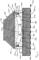
- Fig. 1 shows a simplified cross-sectional view through a press 100 for pressing material 110 according to an embodiment of the present invention.
- the press 100 has at least one roller 120, which is supported on a bearing unit 130 Bracket component 140 is mounted.
- the support member 140 is a fixed axis.
- the roller 120 is part of an assembly referred to as a roller, which also includes the mounting component 140 and the bearing unit 130, among other things.
- the bearing unit 130 which is more closely related to Fig. 2 is arranged and aligned in such a way that the roller 120 is rotatably supported about a rotation line or axis of rotation 150 of the roller 120.
- the rotation line 150 of the roller 120 coincides with an axis of symmetry of the fixed axis (mounting component) 140.
- these can, for example, also have a parallel offset perpendicular to their directions of extension.
- the press 100 also has a die 160, which in the present case is designed as a ring die.
- the ring die 160 is rotatable by one in Fig. 1 Not shown rotation line arranged, which runs parallel to the rotation line 150 of the roller 120. It is driven by a motor that is in Fig. 1 is not shown. In contrast to this, the roller 120 is freely rotatable, that is to say in particular not driven.
- the ring die 160 also has a plurality of openings 170 through which the material 110 is pressed by the roller 120.
- the openings here have a cross section that defines a cross-sectional shape of the pellets 180 produced by the press.
- the press also has one or more optional cutting tools 190 attached to an outside of die 160.
- the die 160 and the roller 120 are in this case designed and spaced such that the material 110 is pressed by the roller 120 through the die 160 when the die is rotated. For this purpose, there is often a preset distance between the die 160 and the roller 120. In other words, the die 160 and the roller 120 are not positively coupled in this arrangement. A rotation of the roller 120 is only brought about by the material 110 filled into the press.
- the distance may also not be present, so that a forced coupling by rolling the roller 120 on the die 160 is effected.
- a forced coupling with an existing or non-existing distance between die 160 and roller 120 can also be realized by a mechanical coupling, for example a gear meshing or a gear. In this way, fixed speed ratios and directions of rotation of the roller 120 and the die 160 relative to one another can also be realized.
- the pellets 180 are cut from the die 160 by one or more optional cutting tools 190. This produces pellets of approximately the same length, while in the absence of the cutting tool (s) 190, the length of the pellets is determined not least by the material properties of the material 110 and the operating parameters of the press (e.g. its rotation speed).
- rollers 120 can also be used in presses according to further exemplary embodiments of the present invention. For example, presses with two, three or more rollers are often used.
- further optional components can be arranged inside the die, such as further support struts or baffles for the material 110.
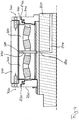
- Fig. 2 shows an enlarged detail of the press 100 Fig.1
- Fig. 2 shows, more specifically, a cross-section through the roller 120, the bearing unit 130 and the fixed axis (holding part) 140 along its rotation or symmetry line 150.
- the bearing unit is - typically by means of a transition fit - applied to the fixed axis (holding component) 140 and secured against axial movement along the axis 140 in a first direction by means of a securing ring 200, for example a snap ring, via a first bearing cover 210.
- a securing ring 200 for example a snap ring
- the bearing unit is secured via a second bearing cover 220 by means of a shaft nut 230 against displacement along the axis 140 in a direction opposite to the first direction.
- the bearing unit can be secured against slipping in the axial direction by other fits and other securing measures, for example by gluing or a tight fit or press fit.
- the bearing unit 130 is also non-positively connected to the roller 120 by means of a tight fit.
- this has a toothing which is designed to interact intensively with the material 110 (not shown in FIG Fig. 2 ) so as to achieve the pressing process between die 160 (not shown in FIG Fig. 2 ) and roller 120 to enable.
- the toothing can, for example, be in the form of a herringbone, semicircular or oblique.
- the roller in a region 250 of the roller 120 lying further inwards, the roller has no special tooth structure or profiling.
- the bearing unit 130 has a double-row tapered roller bearing in an O arrangement, wherein Fig. 2 shows a first rolling element 250 of a first row 260 and a second rolling element 270 of a second row 280.
- the rolling elements 250, 270 are shaped like a truncated cone, as is typical for a tapered roller bearing, and are guided through a first 290 and a second rolling bearing cage 300.
- the pointed sides of the rolling elements 250, 270 face one another (O arrangement).
- the rolling elements of the two rows 260, 280 run in a one-piece outer ring 310 and in a two-piece inner ring 320, which has a first partial inner ring 320-1 and a second partial inner ring 320-2.
- the two partial inner rings 320-1, 320-2 of the inner ring are held together by a fastening device 330 in the form of a perforated metal ring, the holes of which engage in corresponding projections of the two inner rings 320-1, 320-2.
- the fastening device 330 can also be formed by one or more clips or clips.
- the two parts of the inner ring 320 can be connected to one another by another non-positive, positive or material method.
- the exemplary embodiment shown has only the two-part inner ring 320-1, 320-2 ribs for guiding the rolling elements 250, 270, while the common outer ring 310 has no ribs on its running surfaces.
- the storage unit is a self-supporting storage unit that is supplied pre-assembled by the manufacturer before the press 100 is installed and can then be installed as a unit in the press 100 or the wheel rim.
- This makes it possible to set the parameters (for example the internal clearance) of the storage unit 130 separately and in a significantly more controlled and simple manner than if a corresponding setting was only made when the press 100 was assembled.
- it is possible to better adjust the bearing unit 130 to its optimal operating parameters, so that when the press 100 is later operated, it can operate closer to its optimal working point.
- the bearing unit In the area of the perforated metal ring (fastening device 330), the bearing unit has a cavity 340 which can be used, for example, to hold the lubricant reservoir. Before the final assembly of the bearing unit 210, this can be filled with a sufficient amount of a lubricant suitable for the corresponding application, so that safe operation of the bearing unit 210 can be ensured under normal operating conditions for a predetermined operating time (for-life lubrication / lifetime lubrication).
- first 350 and a second sealing element 360 on its sides facing the two bearing caps 220, 230, each in a recess between the inner ring 320 and the outer ring 310 are arranged.
- the exemplary embodiment shown is a cassette seal for grease, each with one, two, three or more radial and axial sealing lips, which seal the bearing unit 130. It can also be optional include other components such as fenders or other elements. Of course, other sealing elements, such as other labyrinth seals or oil seals, can also be used.
- the storage unit 130 as shown in FIG Fig. 2 is shown, two integrated grease seals.
- These sealing units (cassette seals) have an outer jacket made of sheet steel and elastomer. Furthermore, they can have a combination of radial and axial sealing lips as well as integrated mating surfaces and axial sealing lips and axial contact surfaces in various configurations.
- the sealing lips - if they are provided at all - can be implemented with or without tension spring loading.
- One or more protective lips can also be used.
- an integrated bushing for the sealing lip can be used.
- An elastomer seat can optionally also be implemented in the bore and / or on the outer jacket, wherein different elastomer materials can be used for the various elastomer components that may be present.
- a sealing lip loaded with tension spring and three protective lips are used in the frame of the sealing elements.
- the inner construction of the cassette seals can offer the best possible protection against water, dust, mud or other contaminants. It also ensures that the lubricant is safely retained in the bearing.
- the cassette seals can also make the finishing of shafts superfluous.
- the bearing is sealed externally in the form of metallic labyrinth seals or elastomer seals on the roller (also known as a wheel rim or housing).
- the presses are supplied with grease regularly, typically every hour, via automatic central lubrication systems. Due to the high maintenance costs caused by frequent relubrication, it is often not the recommended grease that is used, but a cheaper grease for lubricating the bearing. For economic reasons, the operators of the systems in the food and animal feed sector are tempted not to use food-compatible grease due to the poorer lubricating properties and / or high costs, and thus to run the risk of contamination of the press material, which would contradict legal provisions.
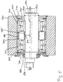
- Fig. 3 shows one Fig. 2 corresponding cross-sectional representation of a conventional bearing arrangement 400.
- the bearing arrangement has a first 410 and a second tapered roller bearing 420, both of which are designed as single-row bearings. In accordance with their single-row design, both have neither a common inner ring nor a common outer ring. Likewise, both are neither self-holding together nor separately.
- an inner ring 430 of the first tapered roller bearing is in contact with a first bearing cover 440, which is mechanically connected to a rigid shaft 470 via a locking ring 450 and a shaft nut 460.
- the screw connection of the shaft nut exerts a force on an outer ring 490 of this tapered roller bearing 410, which is transmitted to a shoulder rim 500 of a roller rim 510.
- the force is transmitted to an outer ring of the second tapered roller bearing 420 via a further shoulder 520 of the wheel rim 510.
- this force is correspondingly transmitted to its inner ring 550 via an outer ring 530 of the second tapered roller bearing 420.
- the force is finally introduced into the rigid axis 470 again via a shoulder 570.
- this flow of force clearly shows that, on the one hand, this conventional bearing arrangement 410 is not self-retaining, so that the bearing arrangement 400 can only be assembled in connection with the final assembly of the press.
- this flow of force also shows that the internal clearance of this bearing arrangement 400 is largely determined by the force exerted via the shaft nut 460. Adjustment can therefore only be carried out as part of the final assembly of the pellet press, since a separate setting to a certain value is impossible due to the lack of self-retaining properties.
- this bearing arrangement 400 will have a less precise adjustment of the bearing clearance, so that the operating point of the pellet press will be less optimal than when using an embodiment of the present invention.
- Fig. 3 a system that requires permanent lubrication or regular relubrication.
- the rigid axle 470 has an opening 580 of a lubricant supply 590, which opens into a cavity 600 between the two tapered roller bearings 410, 420. From there - due to the lack of a seal - the lubricant will pass through the bearings 410, 420 and the two bearing caps 440, 560 into the press chamber.
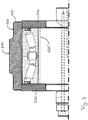
- Fig. 4 shows another of the Fig. 2 Similar representation of a conventional bearing arrangement 700 with a first 710 and a second spherical roller bearing 720.
- the two spherical roller bearings 710, 720 are arranged between a first 730 and a second bearing cover 740, which are screwed to a roller rim 770 of the pellet press via first 750 and second screws 760 ,
- Both spherical roller bearings 710, 720 are in contact with one another in the area of their respective outer rings via a fitting or spacer ring 780, the two bearing caps 730, 740 also being in contact with the outer ring in the assembled state.
- This conventional bearing arrangement 700 is also not self-retaining.
- It also has a cavity 790 in the area of the spacer ring 780 between the two self-aligning bearings 710, 720, into which an opening 800 of a lubricant supply 810 opens in the interior of a standing axis 820.
- Lubricant is supplied to the cavity 790 and thus to the two bearings 710, 720, which can escape into the press chamber via openings 830, 840 in the two bearing caps, so that this bearing arrangement 700 will also contribute to contamination of the material to be pressed by lubricants.
- Fig. 5 shows another of the Fig. 2 Similar cross-sectional view of a conventional bearing assembly 700 ', which differs from the in Fig. 4 differs only slightly, which is why the description of the arrangement Fig. 4 is largely referenced.
- bearing arrangement 700 Fig. 4 stand at the in Fig. 5
- the bearing caps 730, 740 are made in two parts, a part of each cap being in contact with the outer and a part with the respective inner ring of the two adjacent bearings 710, 720.
- both parts are each connected to the wheel rim 770 or the standing axle 820 by means of retaining rings 850, 860.
- a part of the first bearing cover 730 is also connected to the wheel rim 770 via a locking ring 870, while the other part of the first bearing cover 730 is connected to the standing axle 820 via a locking ring 880 and a shaft nut 890.
- This bearing arrangement 700 ' is therefore also not self-retaining
- Fig. 6 shows a cross-sectional view of a bearing unit 130 'according to a further exemplary embodiment of the present invention, which differs from that in FIG Fig. 2 illustrated storage unit 130 in one aspect, so that in addition to the description of that in Fig.2 bearing unit 130 shown.
- the bearing unit 130 In contrast to the one-piece outer ring 310 of the bearing unit 130 Fig. 2 indicates the in Fig. 6 Bearing unit 130 shown on a two-part outer ring 310 with the two parts 310-1 and 310-2, which are assigned to the first tapered roller bearing 260 and the second tapered roller bearing 280 and arranged accordingly.
- the bearing unit 130 ' also has a ring 900 in the region of the end faces of the two parts of the outer ring 130-1, 130-2. This can, for example, with the two parts of the outer ring in sections enter into a positive connection, thus further supporting the self-holding properties.
- the ring 900 can be made from different materials, such as plastic or metal, provided that the material is compatible with the lubricant introduced into the cavity 340.
- FIG. 7 shows a further cross-sectional view through a press 100 according to an exemplary embodiment of the present invention, which differs in terms of storage from that shown in FIG Fig. 6 Storage hardly differs, which is why at this point again on the descriptions of the Figures 6 and 2 is referred.
- the storage unit 130 from Fig. 7 differs from that in Fig. 6 not shown.
- the differences relate to the shape and design of the roller 120 and the two bearing caps 210, 220, apart from structurally determined structures of the holding component 140. While the outer region 240 of the roller hardly differs from the previously described outer regions 240, the inner area 250 at the in Fig. 7 Embodiment shown a significantly lower slope. Rather, this runs essentially parallel to the outer area.
- the exemplary embodiments shown can enable the effects described above.
- a bearing with a precisely defined and reproducible, producible bearing clearance can be created.
- the bearing units 130, 130 'thus have a defined internal clearance and can be sealed and provided with a grease suitable for the application as part of a lifetime lubrication.
- a self-retaining bearing unit 130 generally eliminates the need for maintenance - except in the event of exceptional events and possibly as part of preventive inspections - since these are lubricated for life.
- a central lubrication unit is also no longer required, since the amount of grease and the selection of grease depend on the Application and the service life can be optimized. This means that the operator no longer needs any maintenance and saves time and money.
- the external seal carrier can optionally be omitted, since the seal is integrated in the bearing.
- the sliding seal (sealing elements 350, 360, cassette seals) of the bearing unit 130 in contrast to the previous gap seal, on the one hand enables impurities to not get into the bearing, so that premature bearing failures can be reduced.
- the seal also ensures that the grease essentially does not come out of the storage and the material to be pressed is contaminated.
- a coating of the bearing rings 310, 320 is also provided, or one or more thin intermediate rings are introduced between the bearing rings 310, 320 and the mounting component 140 (fixed axis), which act against "wandering" of the bearing rings 310, 320 in the installed state can fill in the corresponding components with the coating or intermediate ring material by creating the grooves that occur during operation of the press.
- bronze or elastomers can be used as the material for the coating or the intermediate rings.
- the assembly of the bearing units 130 is thus simplified, on the one hand, because of the possibility of fitting intermediate rings, since this replaces a precise adjustment of the individual bearings during the final assembly of the press. In addition, installation errors are largely avoided.
- an exact adjustment of the tapered roller bearings is made possible by the defined, preset axial clearance with little assembly effort. This achieves a more favorable load distribution (distribution of the load over many rolling elements) and extends the service life of the bearings.
- the assembly of the individual components is also dispensed with, since now only a self-supporting bearing unit 130, into which all components can already be integrated, has to be installed.
- the bearing units 130 can also have optional quick assembly devices, for example. These can be a simple one Contact area as well as a more complex structure, such as a coupling or a press fit.
- Bearing units 130 are used in the motor vehicle field, and here in particular in the heavy load force region. These are also referred to as so-called “Truck Hub Units” (THU), but have basic load ratings that cannot actually be used for pellet presses.
- TNU Trust Hub Units
- the present invention is also based on the finding that, due to the much better adaptation of the internal clearance, the loads in the area of roller bearings in presses are lower, as test series and calculations have shown. Although bearing units from the motor vehicle sector cannot actually be used in the press sector due to the low load capacities according to the conventional approach, they can very well be used due to the better adapted internal clearance and the associated reduced fatigue.
- double-row or multi-row, self-holding bearing units are therefore used, in which optionally a defined axial and / or radial bearing clearance is set.
- these can optionally have a common outer and / or inner ring. They can also be optionally equipped with an integrated seal.
- they can also be filled with lubricant.
- a coating of the rolling element raceways and / or bearing ring surfaces is also possible.
- the storage units can also optionally have a quick assembly device, for. B. a hydraulically or electrically generated press fit or a correspondingly generated coupling.
Landscapes
- Engineering & Computer Science (AREA)
- General Engineering & Computer Science (AREA)
- Mechanical Engineering (AREA)
- Rolling Contact Bearings (AREA)
Description
Ausführungsbeispiele der vorliegenden Erfindung beziehen sich auf Pressen zum Pressen eines Materials, beispielsweise Pelletieranlagen oder Pelletpressen, wie sie in der holzverarbeitenden Industrie oder der Nahrungsmittel-, der Nahrungsmittelergänzungs- oder Kraftfuttermittelindustrie verwendet werden können.Embodiments of the present invention relate to presses for pressing a material, for example pelletizing plants or pellet presses, as can be used in the woodworking industry or in the food, food supplement or concentrated feed industry.
Viele Materialien werden zur Weiterverarbeitung oder zum Verbrauch in Form kleiner gepresster Körper, sogenannter Pellets, vertrieben. Hierbei wird das Ausgangsmaterial häufig in kugel- oder zylinderförmiger, verdichteter Form durch Pressen in sogenannten Pelletieranlagen oder -pressen hergestellt. So wird beispielsweise Holz oder Kraftfuttermittel für die Mast und/oder die Ernährung von Nutztieren in Pelletform vertrieben.Many materials are sold for further processing or consumption in the form of small pressed bodies, so-called pellets. Here, the starting material is often produced in a spherical or cylindrical, compressed form by pressing in so-called pelletizing plants or presses. For example, wood or concentrated feed for fattening and / or feeding farm animals is sold in pellet form.
Pelletieranlagen umfassen im Allgemeinen einen oder mehrere Koller, die auf einer Ring- oder Flachmatrize das zu verarbeitende Material in Pellets pressen. Der Koller umfasst hierbei die eigentliche Kollerfelge (Walze), aber ebenso Lagerdeckel, die Lager und auch die Achse. Die Walzen werden dabei mit zwei Einzellagern gelagert, bei denen es sich um angestellte Kegelrollenlager oder Pendelrollenlager handelt. Bei der Lagerung mit konventionellen Kegelrollenlagern ist eine Anstellung unverzichtbar, wobei sie bei der Montage einen hohen Aufwand und Erfahrung erfordert. Eine kollektive, und damit zufällige Anstellung aller Kegelrollenlager gemeinsam kann nur dann erfolgen, wenn es die Betriebsbedingungen zulassen d. h. keine hohen Anforderungen an die Lagerung gestellt werden.Pelletizing plants generally comprise one or more mills that press the material to be processed into pellets on a ring or flat die. The koller includes the actual koller rim (roller), but also the bearing cap, the bearings and the axle. The rollers are supported with two individual bearings, which are tapered roller bearings or spherical roller bearings. Employment is indispensable for storage with conventional tapered roller bearings, which requires a great deal of effort and experience during assembly. A collective, and thus accidental employment of all tapered roller bearings can only take place if the operating conditions allow it d. H. no high demands are placed on the storage.
Aufgrund von hohen Lasten und Stößen, denen die Walzen während des Betriebs ausgesetzt sind, stellen Pelletieranlagen hohe Anforderungen an die Lagerung. Aus diesem Grund sollte die Montage so genau wie möglich durchgeführt werden. In der Realität wird jedoch - nicht zuletzt aus Kostengründen - die Anstellung ungenau vorgenommen, um die Montage einfacher und damit kosteneffizienter durchzuführen. Somit werden Pelletieranlagen häufig nicht im Bereich ihrer maximalen Leistungsfähigkeit oder im Bereich eines erhöhten Verschleißes betrieben.Due to the high loads and shocks to which the rollers are exposed during operation, pelleting systems place high demands on storage. For this reason, the assembly should be carried out as accurately as possible. In reality it will however - not least for cost reasons - the job was made inaccurately in order to make the assembly easier and therefore more cost-effective. Pelleting systems are therefore often not operated in the area of their maximum performance or in the area of increased wear.
Hinzu tritt, dass durch die verarbeiteten Materialien häufig eine hohe Kontaminationsgefahr für die Lager besteht. Die Umgebungsbedingungen weisen entsprechend einen sehr hohen Verschmutzungsgrad auf, sodass regelmäßig, beispielsweise stündlich, nachgeschmiert werden muss, um die eingedrungenen Verschmutzungspartikel aus den Lagern wieder herauszudrücken. Hierdurch sind Wartungsaufwand und -kosten für den Betreiber enorm.In addition, the materials used often pose a high risk of contamination for the bearings. The ambient conditions accordingly have a very high degree of contamination, so that relubrication must be carried out regularly, for example every hour, in order to push the penetrated contamination particles out of the bearings again. As a result, the maintenance effort and costs for the operator are enormous.
Im Falle von Pelletiermaschinen im Bereich der Kraftfutterherstellung müssen diese Anlagen ferner schon aufgrund gesetzlicher Bestimmungen mit lebensmittelverträglichem Fett geschmiert werden, da das Fett in das Pressgut gelangen kann. Aufgrund der hohen Anforderung an die Schmiereigenschaften, also beispielsweise einem guten Verschleißschutz und einer entsprechenden Temperaturbeständigkeit, sind herkömmliche lebensmittelverträgliche Fette kaum geeignet, hochwertige und geeignete jedoch sehr teuer.In the case of pelleting machines in the field of concentrated feed production, these systems must also be lubricated with food-compatible grease due to legal regulations, since the grease can get into the pressed material. Due to the high demands on the lubricating properties, for example good wear protection and appropriate temperature resistance, conventional food-compatible greases are hardly suitable, but high-quality and suitable ones are very expensive.
Die
Die
Ausgehend hiervon besteht die Aufgabe der vorliegenden Erfindung darin, einen verbesserten Betrieb einer Presse zum Pressen von Material zu ermöglichen.Based on this, the object of the present invention is to enable improved operation of a press for pressing material.
Diese Aufgabe wird durch eine Presse gemäß Anspruch 1 oder die Verwendung einer selbsthaltenden Lagereinheit aus dem Kraftfahrzeugbereich gemäß Anspruch 10 gelöst.This object is achieved by a press according to claim 1 or the use of a self-supporting bearing unit from the motor vehicle sector according to claim 10.
Ein Ausführungsbeispiel einer Presse zum Pressen eines Materials umfasst eine Walze, eine Matrize, die derart ausgebildet ist, dass das Material zwischen der Walze und der Matrize pressbar ist, und eine Lagereinheit, die die Walze aufnimmt und ausgebildet ist, um die Walze zu lagern, wobei die Lagereinheit als selbsthaltende zwei- oder mehrreihige Lagereinheit ausgeführt ist.An embodiment of a press for pressing a material comprises a roller, a die, which is designed such that the material can be pressed between the roller and the die, and a bearing unit, which receives the roller and is designed to store the roller, wherein the storage unit is designed as a self-holding two-row or multi-row storage unit.
In Ausführungsbeispielen der vorliegenden Erfindung wird eine selbsthaltende Lagereinheit aus dem Kraftfahrzeugbereich mit einer in einem vorbestimmten Lagerluftbereich liegenden Lagerluft zur Lagerung einer Walze einer solchen Presse verwendet, wobei die Lagereinheit zwei- oder mehrreihig ausgeführt ist und eine Schmiermittelmenge und ein Dichtelement aufweist, wobei das Dichtelement ausgebildet ist, um ein Eindringen von Verunreinigungen in die Lagereinheit und ein Austreten von Schmiermittel zu unterbinden, und wobei die Schmiermittelmenge derart bemessen ist, um einen sicheren Betrieb der Lagereinheit über eine vorbestimmte Betriebsdauer zu ermöglichen.In exemplary embodiments of the present invention, a self-supporting bearing unit from the motor vehicle area with a bearing air lying in a predetermined bearing air area is used to support a roller of such a press, the bearing unit being designed in two or more rows and having an amount of lubricant and a sealing element, the sealing element being formed is to prevent the ingress of contaminants into the bearing unit and the escape of lubricant, and the amount of lubricant is dimensioned in such a way as to enable safe operation of the bearing unit over a predetermined operating period.
Ausführungsbeispielen der vorliegenden Erfindung liegt die Erkenntnis zugrunde, dass ein verbesserter Betrieb einer Presse zum Pressen eines Materials dadurch erzielt werden kann, indem anstelle der bisher verwendeten Anordnung mehrerer einreihiger Kegelrollenlager oder mehrerer Pendelrollenlager eine selbsthaltende Lagereinheit zum Einsatz gebracht wird, die als zwei- oder mehrreihige Lagereinheit ausgeführt ist. Dadurch, dass diese zwei- oder mehrreihige Lagereinheit selbsthaltend ausgeführt ist, ist es möglich, diese vor Montage der Presse gezielt hinsichtlich Lagerluft und gegebenenfalls anderer betriebswesentlicher Parameter einzustellen. Eine selbsthaltende Lagereinheit ist eine solche, die vormontierbar ist, also insbesondere nicht nur radiale Kräfte, sondern auch axiale Kräfte in beide axialen Richtungen aufnehmen kann. Anders ausgedrückt ist eine Lagereinheit, wie sie im Rahmen von Ausführungsbeispielen der vorliegenden Erfindung verwendet wird, ausgebildet, um radiale und axiale Kräfte entlang ihrer Lagerachse, die z. B. mit einer Rotationsachse der Welle einer Presse zusammenfallen kann, in beide Richtungen aufzunehmen.Embodiments of the present invention are based on the knowledge that an improved operation of a press for pressing a material can be achieved by using a self-retaining bearing unit, which is used as a two or more rows, instead of the arrangement of multiple single-row tapered roller bearings or multiple spherical roller bearings used previously Storage unit is executed. Because this double-row or multi-row bearing unit is designed to be self-retaining, it is possible to set it specifically with regard to bearing clearance and possibly other operational parameters before the press is installed. A self-supporting bearing unit is one that can be preassembled, that is, in particular, it can absorb not only radial forces, but also axial forces in both axial directions. In other words, a bearing unit, as is used in the context of exemplary embodiments of the present invention, is designed to withstand radial and axial forces along its bearing axis, which, for. B. can coincide with an axis of rotation of the shaft of a press, in both directions.
Darüber hinaus ist es möglich, bei Ausführungsbeispielen der vorliegenden Erfindung die Lagereinheit mit einem Schmiermittelvorrat auszustatten, der gerade so bemessen ist, dass ein sicherer Betrieb der Lagereinheit über eine vorbestimmte Betriebsdauer sichergestellt ist. Durch das Einbringen eines Dichtelements bzw. zwei oder mehrerer entsprechender Dichtelemente kann die Lagereinheit darüber hinaus so ausgeführt werden, dass ein Austreten des Schmiermittels und ein Eintreten von Verunreinigungen in die Lagereinheit im Wesentlichen vollständig unterbunden werden. Hierdurch ist es möglich, die Wartungsintervalle und den Wartungsaufwand deutlich zu reduzieren, und die Presse trotzdem im Bereich ihres optimalen Arbeitspunktes oder -bereichs zu betreiben.In addition, it is possible in the case of exemplary embodiments of the present invention to provide the bearing unit with a lubricant supply which is dimensioned such that safe operation of the bearing unit is ensured over a predetermined operating time. By inserting a sealing element or two or more corresponding sealing elements, the bearing unit can also be designed such that leakage of the lubricant and entry of contaminants into the bearing unit are substantially completely prevented. This makes it possible to significantly reduce the maintenance intervals and maintenance effort, and still operate the press in the area of its optimal working point or area.
Dies kann beispielsweise durch die Verwendung einer entsprechenden Lagereinheit aus dem Kraftfahrzeugbereich, beispielsweise aus dem Nutzkraftfahrzeugbereich bzw. aus dem Lastkraftfahrzeugbereich, geschehen.This can be done, for example, by using a corresponding storage unit from the motor vehicle area, for example from the commercial vehicle area or from the truck area.
Ausführungsbeispiele der vorliegenden Erfindung werden unter Bezugnahme auf die beiliegenden Figuren näher erläutert.
-
Fig. 1 zeigt eine schematische Darstellung einer Presse zum Pressen eines Materials gemäß einem Ausführungsbeispiel der vorliegenden Erfindung; -
Fig. 2 zeigt eine Querschnittsdarstellung durch eine Lagereinheit einer Presse gemäß einem Ausführungsbeispiel der vorliegenden Erfindung; -
Fig. 3 zeigt eine Querschnittsdarstellung durch eine Pelletiermaschine gemäß einem ersten Vergleichsbeispiel; -
Fig. 4 zeigt eine Querschnittsdarstellung durch eine Pelletiermaschine gemäß einem zweiten Vergleichsbeispiel; -
Fig. 5 zeigt eine Querschnittsdarstellung durch eine Pelletiermaschine gemäß einem dritten Vergleichsbeispiel; -
Fig. 6 zeigt eine Querschnittsdarstellung durch eine Lagereinheit einer Presse gemäß einem Ausführungsbeispiel der vorliegenden Erfindung; und -
Fig. 7 zeigt eine Querschnittsdarstellung durch eine Lagereinheit einer Presse gemäß einem weiteren Ausführungsbeispiel der vorliegenden Erfindung;
-
Fig. 1 shows a schematic representation of a press for pressing a material according to an embodiment of the present invention; -
Fig. 2 shows a cross-sectional view through a bearing unit of a press according to an embodiment of the present invention; -
Fig. 3 shows a cross-sectional view through a pelleting machine according to a first comparative example; -
Fig. 4 shows a cross-sectional view through a pelleting machine according to a second comparative example; -
Fig. 5 shows a cross-sectional view through a pelleting machine according to a third comparative example; -
Fig. 6 shows a cross-sectional view through a bearing unit of a press according to an embodiment of the present invention; and -
Fig. 7 shows a cross-sectional view through a bearing unit of a press according to a further embodiment of the present invention;
Im Folgenden werden unter Bezugnahme auf die
Die Lagereinheit 130, die näher im Zusammenhang mit
Die Presse 100 weist ferner eine Matrize 160 auf, die im vorliegenden Fall als Ringmatrize ausgeführt ist. Die Ringmatrize 160 ist drehbar um eine in
Die Ringmatrize 160 weist ferner eine Mehrzahl von Öffnungen 170 auf, durch die das Material 110 durch die Walze 120 gepresst wird. Die Öffnungen weisen hierbei einen Querschnitt auf, der eine Querschnittsform der von der Presse erzeugten Pellets 180 definiert. Die Presse weist ferner ein oder mehrere optionale Schneidwerkzeuge 190 auf, die an einer Außenseite der Matrize 160 angebracht sind.The ring die 160 also has a plurality of
Die Matrize 160 und die Walze 120 sind hierbei derart ausgebildet und beabstandet, dass das Material 110 bei Drehung der Matrize von der Walze 120 durch die Matrize 160 hindurch gepresst wird. Zu diesem Zweck besteht zwischen der Matrize 160 und der Walze 120 häufig ein voreingestellter Abstand. Anders ausgedrückt sind bei dieser Anordnung die Matrize 160 und die Walze 120 nicht zwangsgekoppelt. Eine Rotation der Walze 120 wird erst durch das in die Presse eingefüllte Material 110 bewirkt.The
Bei anderen Ausführungsbeispielen kann hingegen der Abstand ebenso nicht vorhanden sein, sodass eine Zwangskopplung durch ein Abrollen der Walze 120 an der Matrize 160 bewirkt wird. Ebenso kann auch eine Zwangskopplung bei einem bestehenden oder nicht bestehenden Abstand zwischen Matrize 160 und Walze 120 durch eine mechanische Kopplung, etwa ein Zahnradeingriff oder ein Getriebe realisiert sein. Hierdurch können auch feste Drehzahlverhältnisse und Rotationsrichtungen der Walze 120 und der Matrize 160 zueinander realisiert werden.In other exemplary embodiments, on the other hand, the distance may also not be present, so that a forced coupling by rolling the
Durch eines oder mehrere optionale Schneidwerkzeuge 190 werden die Pellets 180 von der Matrize 160 abgeschnitten. Hierdurch werden Pellets mit etwa gleichbleibender Länge erzeugt, während im Falle des Fehlens des oder der Schneidwerkzeuge 190 die Länge der Pellets nicht zuletzt durch die Materialeigenschaften des Materials 110 und die Betriebsparameter der Presse (z. B. ihre Rotationsgeschwindigkeit) bestimmt wird.The
Selbstverständlich können bei Pressen gemäß weiteren Ausführungsbeispielen der vorliegenden Erfindung auch abweichende Anzahlen von Walzen 120 zum Einsatz kommen. So werden beispielsweise häufig Pressen mit zwei, drei oder mehreren Walzen verwendet. Ebenso können weitere optionale Komponenten im Inneren der Matrize angeordnet sein, etwa weitere Stützstreben oder Leitbleche für das Material 110.Of course, different numbers of
Selbstverständlich kann die Lagereinheit bei anderen Ausführungsbeispielen der vorliegenden Erfindung durch andere Passungen und andere Sicherungsmaßnahmen gegen ein Verrutschen in axialer Richtung gesichert werden, etwa durch ein Verkleben oder eine Stramm- oder Presspassung.Of course, in other exemplary embodiments of the present invention, the bearing unit can be secured against slipping in the axial direction by other fits and other securing measures, for example by gluing or a tight fit or press fit.
Mittels einer Strammpassung ist die Lagereinheit 130 ferner mit der Walze 120 kraftschlüssig verbunden. In einem äußeren Bereich 240 der Walze 120 weist diese eine Verzahnung auf, die ausgebildet ist, um eine intensive Wechselwirkung mit dem Material 110 (nicht gezeigt in
Die Lagereinheit 130 weist ein zweireihiges Kegelrollenlager in O-Anordnung auf, wobei
Bei dem in
In weiteren Ausführungsbeispielen der vorliegenden Erfindung kann die Befestigungseinrichtung 330 ebenfalls durch einen oder mehrere Klammern oder Clipps gebildet sein. Ebenso können die beiden Teile des Innenrings 320 durch ein anderes kraft-, form- oder stoffschlüssiges Verfahren miteinander verbunden werden.In further exemplary embodiments of the present invention, the
Bei dem in
Aufgrund der Ausgestaltung des gemeinsamen, einteiligen Außenrings 310, der O-Anordnung der beiden Reihen 260, 280 der Wälzkörper 250, 270, des zweigeteilten Innenrings 320 mit den beiden Teilen 320-1 und 320-2 sowie dem gelochten Metallring (Befestigungseinrichtung) 330, handelt es sich bei der Lagereinheit um eine selbsthaltende Lagereinheit, die vor der Montage der Presse 100 vom Hersteller vormontiert geliefert und als Einheit dann in die Presse 100 oder die Kollerfelge montiert werden kann. Hierdurch ist es möglich, die Parameter (z. B. die Lagerluft) der Lagereinheit 130 separat und deutlich kontrollierter und einfacher einzustellen, als wenn eine entsprechende Einstellung erst im Rahmen des Zusammenbaus der Presse 100 erfolgen würde. Als Folge ist es möglich, die Lagereinheit 130 besser auf ihre optimalen Betriebsparameter einzustellen, sodass beim späteren Betrieb der Presse 100 diese näher an ihrem optimalen Arbeitspunkt operieren kann.Due to the design of the common, one-piece
Im Bereich des gelochten Metallrings (Befestigungseinrichtung 330) weist die Lagereinheit einen Hohlraum 340 auf, der beispielsweise zur Aufnahme des Schmiermittelreservoirs dienen kann. Dieses kann vor der Endmontage der Lagereinheit 210 mit einer ausreichenden Menge eines für die entsprechende Anwendung geeigneten Schmiermittels befüllt werden, sodass ein sicherer Betrieb der Lagereinheit 210 unter normalen Betriebsbedingungen für eine vorbestimmte Betriebsdauer sichergestellt werden kann (For-Life-Schmierung / Lebensdauerschmierung).In the area of the perforated metal ring (fastening device 330), the bearing unit has a
Bei der Auswahl eines entsprechenden Schmiermittels sind sowohl die mechanischen und damit die thermischen Belastungen, als auch andere Betriebsparameter zu beachten. So kann es gegebenenfalls sinnvoll sein, als Schmiermittel ein lebensmittelverträgliches Fett zu verwenden. Als Schmiermittel können jedoch ebenso Öle und andere Fette, sowie Feststoffschmiermittel verwendet werden.When choosing a suitable lubricant, the mechanical and thus the thermal loads as well as other operating parameters must be taken into account. It may make sense to use a food-compatible grease as a lubricant. However, oils and other greases as well as solid lubricants can also be used as lubricants.
Um einerseits ein Austreten des Schmiermittels und andererseits ein Eintreten von Verunreinigungen in die Lagereinheit 130 zu unterbinden, weist diese an ihren den beiden Lagerdeckeln 220, 230 zugewandten Seiten ferner ein erstes 350 und ein zweites Dichtelement 360 auf, die jeweils in einer Aussparung zwischen dem Innenring 320 und dem Außenring 310 angeordnet sind. Bei dem in
Genauer gesagt weist die Lagereinheit 130, wie sie in
Als weitere Option kann eine integrierte Laufbuchse für die Dichtlippe verwendet werden. Auch kann optional ein Elastomersitz in der Bohrung und/oder am Außenmantel implementiert werden, wobei für die verschiedenen gegebenenfalls vorhandenen Elastomerbauteile verschiedene Elastomer-Werkstoffe herangezogen werden können. In dem gezeigten Ausführungsbeispiel werden beispielsweise eine zugfederbelastete Dichtlippe und drei Schutzlippen im Rahmen der Dichtelemente verwendet.As an additional option, an integrated bushing for the sealing lip can be used. An elastomer seat can optionally also be implemented in the bore and / or on the outer jacket, wherein different elastomer materials can be used for the various elastomer components that may be present. In the exemplary embodiment shown, for example a sealing lip loaded with tension spring and three protective lips are used in the frame of the sealing elements.
Die innere Konstruktion der Kassettendichtungen kann so einen bestmöglichen Schutz gegen Wasser, Staub, Schlamm oder andere Verunreinigungen bieten. Zudem sorgt sie für den sicheren Rückhalt des Schmierstoffs in der Lagerstelle. Die Kassettendichtungen können gegebenenfalls zudem die Feinbearbeitung von Wellen überflüssig machen.The inner construction of the cassette seals can offer the best possible protection against water, dust, mud or other contaminants. It also ensures that the lubricant is safely retained in the bearing. The cassette seals can also make the finishing of shafts superfluous.
Um den Unterschied zwischen Ausführungsbeispielen der vorliegenden Erfindung und konventionellen Pressen mit entsprechenden Lageranordnungen zu illustrieren, werden nunmehr kurz im Zusammenhang mit den
Bisher werden zwei einreihige Kegelrollen- oder zwei Pendelrollenlager bei entsprechenden Pelletpressen eingesetzt. Bei der Ausführung mit Kegelrollenlagern erfolgt das Anstellen meist während des Zusammenbaus der Presse manuell und daher häufig zufällig. Die tatsächlich eingestellte Lagerluft bzw. Vorspannung wird nach der Montage nicht kontrolliert, sodass dieser Wert unbekannt bleibt. Damit ist mit einer großen Streuung und schlimmstenfalls mit einer Reduzierung der Lagerlebensdauer der Presse zu rechnen.So far, two single-row tapered roller bearings or two spherical roller bearings have been used with corresponding pellet presses. In the version with tapered roller bearings, starting is usually done manually during the assembly of the press and is therefore often random. The actual set internal clearance or preload is not checked after assembly, so this value remains unknown. This means that there is a large spread and, in the worst case, a reduction in the bearing life of the press.
Die Lagerung wird extern abgedichtet in Form von metallischen Labyrinthdichtungen oder Elastomerdichtungen an der Walze (auch als Kollerfelge oder Gehäuse bezeichnet). Die Pressen werden über automatische Zentralschmiersysteme regelmäßig, typischerweise stündlich, mit Fett versorgt. Aufgrund von hohen Wartungskosten bedingt durch die häufige Nachschmierung wird oft auch nicht das empfohlene Fett, sondern ein preiswerteres Fett zur Schmierung der Lagerung benutzt. Die Betreiber der Anlagen im Lebens- bzw. Futtermittelbereich werden daher schon aus ökonomischen Gründen in Versuchung geführt, aufgrund der schlechteren Schmiereigenschaften und/oder hohe Kosten kein lebensmittelverträgliches Fett einzusetzen und dadurch das Risiko einer Verunreinigung des Pressmaterials einzugehen, was rechtlichen Bestimmungen widersprechen würde.The bearing is sealed externally in the form of metallic labyrinth seals or elastomer seals on the roller (also known as a wheel rim or housing). The presses are supplied with grease regularly, typically every hour, via automatic central lubrication systems. Due to the high maintenance costs caused by frequent relubrication, it is often not the recommended grease that is used, but a cheaper grease for lubricating the bearing. For economic reasons, the operators of the systems in the food and animal feed sector are tempted not to use food-compatible grease due to the poorer lubricating properties and / or high costs, and thus to run the risk of contamination of the press material, which would contradict legal provisions.
Ein Innenring 430 des ersten Kegelrollenlagers steht - im montierten Zustand der Pelletpresse - mit einem ersten Lagerdeckel 440 in Kontakt, der über einen Sicherungsring 450 und eine Wellenmutter 460 mit einer starren Achse 470 mechanisch verbunden ist. Über die kegelförmigen Wälzkörper 480 des ersten Kegelrollenlagers 410 übt die Verschraubung der Wellenmutter eine Kraft auf einen Außenring 490 dieses Kegelrollenlagers 410 aus, die über eine Schulter 500 einer Kollerfelge 510 auf diese übertragen wird. Über eine weitere Schulter 520 der Kollerfelge 510 wird die Kraft auf einen Außenring des zweiten Kegelrollenlagers 420 übertragen. Aufgrund einer O-Anordnung der Kegelrollenlager 410, 420 wird diese Kraft entsprechend über einen Außenring 530 des zweiten Kegelrollenlagers 420, seine Wälzkörper 540 auf seinen Innenring 550 übertragen. Über einen mit dem Innenring 550 in Kontakt stehenden zweiten Lagerdeckel 560 wird die Kraft schließlich wieder über eine Schulter 570 der starren Achse 470 in diese eingeleitet.In the assembled state of the pellet press, an
Dieser Kraftfluss zeigt deutlich, dass einerseits diese konventionelle Lageranordnung 410 nicht selbsthaltend ist, sodass eine Montage der Lageranordnung 400 erst im Zusammenhang mit der Endmontage der Presse erfolgen kann. Andererseits zeigt dieser Kraftfluss aber ebenso, dass die Lagerluft dieser Lageranordnung 400 stark von der über die Wellenmutter 460 ausgeübten Kraft bestimmt wird. Eine Justage kann folglich nur im Rahmen der Endmontage der Pelletpresse erfolgen, da aufgrund der fehlenden selbsthaltenden Eigenschaft eine separate Einstellung auf einen bestimmten Wert unmöglich ist. Da jedoch eine entsprechende Einstellung - wie zuvor dargestellt - bei der Endmontage kaum möglich ist, wird diese Lageranordnung 400 eine weniger präzise Einstellung der Lagerluft aufweisen, sodass der Arbeitspunkt der Pelletpresse weniger optimal sein wird, als unter Verwendung eines Ausführungsbeispiels der vorliegenden Erfindung.This flow of force clearly shows that, on the one hand, this
Darüber hinaus zeigt
Auch weist sie darüber hinaus einen Hohlraum 790 im Bereich des Abstandsrings 780 zwischen den beiden Pendellagern 710, 720 auf, in den eine Öffnung 800 einer Schmiermittelversorgung 810 im Inneren einer stehenden Achse 820 mündet. Über diese werden dem Hohlraum 790 und damit den beiden Lagern 710, 720 Schmiermittel zugeführt, das über Öffnungen 830, 840 in den beiden Lagerdeckeln in den Pressraum austreten kann, sodass auch diese Lageranordnung 700 zu einer Verunreinigung des zu pressenden Materials durch Schmiermittel beitragen wird.It also has a
Auch weist sie wiederum ein entsprechendes Schmiermittelsystem 810 mit der Öffnung 800 zu dem Hohlraum 790 auf, was zu einer Kontamination des zu pressenden Materials mit Schmiermittel führen kann.It also has a
Im Unterschied zu dem einteilig ausgeführten Außenring 310 der Lagereinheit 130 aus
Die Lagereinheit 130 aus
Ein weiterer Unterschied besteht in der konkreten Ausgestaltung der Lagerdeckel 210, 220, die bei dem in
Auch die in den
Durch den Einsatz einer selbsthaltenden Lagereinheit 130 entfällt die Wartung - außer bei außergewöhnlichen Ereignissen und gegebenenfalls im Rahmen von Vorsorgeinspektionen - im Allgemeinen komplett, da diese auf Lebenszeit geschmiert werden. Es wird ebenfalls keine Zentralschmiereinheit mehr benötigt, da die Fettmenge und die Fettauswahl auf die Anwendung und die Standzeit optimiert werden kann. Der Betreiber hat dadurch keinen Wartungsaufwand mehr und spart Zeit und Geld.The use of a self-retaining
Außerdem kann auch der externe Dichtungsträger optional entfallen, da die Dichtung in die Lagerung integriert wird. Die schleifende Abdichtung (Dichtelemente 350, 360, Kassettendichtungen) der Lagereinheit 130 ermöglicht im Gegensatz zu der bisherigen Spaltdichtung einerseits, dass Verunreinigungen nicht in die Lagerung gelangen können, sodass somit vorzeitige Lagerausfälle reduziert werden können. Andererseits gewährleistet die Abdichtung auch, dass das Fett im Wesentlichen nicht aus der Lagerung tritt und das Pressgut verunreinigt wird.In addition, the external seal carrier can optionally be omitted, since the seal is integrated in the bearing. The sliding seal (sealing
Erfindungsgemäß ist ferner eine Beschichtung der Lagerringe 310, 320 vorgesehen, oder sind ein oder mehrere dünne Zwischenringe zwischen die Lagerringe 310, 320 und das Halterungsbauteil 140 (feststehende Achse) eingebracht, die gegen ein "Wandern" der Lagerringe 310, 320 im eingebauten Zustand wirken können, indem diese beim Betrieb der Presse entstehende Riefen in den entsprechenden Bauteilen mit dem Beschichtungs- oder Zwischenringmaterial auffüllen. Als Material für die Beschichtung oder die Zwischenringe kommen grundsätzlich erfindungsgemäß Bronze, oder auch Elastomere infrage.According to the invention, a coating of the bearing rings 310, 320 is also provided, or one or more thin intermediate rings are introduced between the bearing rings 310, 320 and the mounting component 140 (fixed axis), which act against "wandering" of the bearing rings 310, 320 in the installed state can fill in the corresponding components with the coating or intermediate ring material by creating the grooves that occur during operation of the press. In principle, according to the invention, bronze or elastomers can be used as the material for the coating or the intermediate rings.
Die Montage der Lagereinheiten 130 wird somit einerseits wegen der Möglichkeit des Einpassens von Zwischenringen vereinfacht, da dies eine genaue Anstellung der einzelnen Lager während der Endmontage der Presse ersetzt. Außerdem werden Einbaufehler weitgehend vermieden. Bei der neuen Lösung mit der Lagereinheit 130 wird eine genaue Anstellung der Kegelrollenlager durch die definierte voreingestellte Axialluft bei geringem Montageaufwand ermöglicht. Dadurch wird eine günstigere Lastverteilung (Verteilung der Last auf viele Wälzkörper) erreicht und die Standzeit der Lager verlängert.The assembly of the bearing
Darüber hinaus entfällt auch die Montage der einzelnen Komponenten (d. h. zwei einreihige Kegelrollenlager, externe Dichtungsträger etc.), da nun nur eine selbsthaltende Lagereinheit 130, in die bereits alle Komponenten integriert sein können, einzubauen ist. Um die Montage zu erleichtern, können die Lagereinheiten 130 beispielsweise ebenfalls optionale Schnellmontagevorrichtungen aufweisen. Bei diesen kann es sich um eine einfache Anlagefläche ebenso wie um eine komplexere Struktur handeln, etwa eine Kupplung oder einen Pressverband.In addition, the assembly of the individual components (ie two single-row tapered roller bearings, external seal carriers, etc.) is also dispensed with, since now only a self-supporting
Lagereinheiten 130 gemäß Ausführungsbeispielen der vorliegenden Erfindung werden im Kraftfahrzeugbereich, und hier insbesondere im Schwerlastkraftbereich verwendet. Diese werden auch als sogenannte "Truck Hub Units" (THU) bezeichnet, weisen jedoch Tragzahlen auf, die für Pelletpressen eigentlich nicht verwendbar sind.
Der vorliegenden Erfindung liegt jedoch ferner die Erkenntnis zugrunde, dass aufgrund der wesentlich besseren Anpassung der Lagerluft die Belastungen im Bereich der Lagerung von Walzen bei Pressen geringer ausfallen, wie Versuchsreihen und Berechnungen gezeigt haben. Obwohl also eigentlich Lagereinheiten aus dem Kraftfahrzeugbereich aufgrund zu geringer Tragzahlen eigentlich nach konventioneller Herangehensweise nicht im Pressenbereich einsetzbar sind, können diese sehr wohl aufgrund der besser angepassten Lagerluft und dem damit einhergehenden geringeren Ermüdung verwendet werden.However, the present invention is also based on the finding that, due to the much better adaptation of the internal clearance, the loads in the area of roller bearings in presses are lower, as test series and calculations have shown. Although bearing units from the motor vehicle sector cannot actually be used in the press sector due to the low load capacities according to the conventional approach, they can very well be used due to the better adapted internal clearance and the associated reduced fatigue.
Aus dem gleichen Grund ist beobachtet worden, dass auch die Lagertemperaturen im Betrieb geringer als bei konventionellen Pelletpressen ausfallen. Dies ermöglicht eine breitere Auswahl an zur Verfügung stehenden Schmiermitteln für die einzelnen Anwendungsgebiete.For the same reason, it has been observed that the storage temperatures during operation are also lower than with conventional pellet presses. This enables a wider selection of available lubricants for the individual areas of application.
Bei Ausführungsbeispielen der vorliegenden Erfindung werden daher zwei- oder mehrreihige, selbsthaltende Lagereinheiten verwendet, bei denen optional eine definierte axiale und/oder radiale Lagerluft eingestellt ist. Ferner können diese optional einen gemeinsamen Außen- und/oder Innenring aufweisen. Ebenso optional können diese mit einer integrierten Abdichtung versehen werden. Optional können sie auch mit Schmiermittel befüllt werden. Optional ist darüber hinaus auch eine Beschichtung der Wälzkörperlaufbahnen und/oder Lagerringflächen möglich. Ebenso optional können die Lagereinheiten eine Schnellmontagevorrichtung aufweisen, z. B. einen hydraulisch oder elektrisch generierter Pressverband oder eine entsprechend generierte Kupplung.In exemplary embodiments of the present invention, double-row or multi-row, self-holding bearing units are therefore used, in which optionally a defined axial and / or radial bearing clearance is set. Furthermore, these can optionally have a common outer and / or inner ring. They can also be optionally equipped with an integrated seal. Optionally, they can also be filled with lubricant. Optionally, a coating of the rolling element raceways and / or bearing ring surfaces is also possible. The storage units can also optionally have a quick assembly device, for. B. a hydraulically or electrically generated press fit or a correspondingly generated coupling.
- 100100
- PressePress
- 110110
- Materialmaterial
- 120120
- Walzeroller
- 130130
- Lagereinheitstorage unit
- 140140
- Halterungsbauteilsupport member
- 150150
- Rotationsliniepress line
- 160160
- Matrizedie
- 170170
- Öffnungenopenings
- 180180
- Pelletspellets
- 190190
- Schneidwerkzeugcutting tool
- 200200
- Sicherungsringcirclip
- 210210
- erster Lagerdeckelfirst bearing cover
- 220220
- zweiter Lagerdeckelsecond bearing cap
- 230230
- Wellenmuttershaft nut
- 240240
- äußerer Bereichouter area
- 250250
- erster Wälzkörperfirst rolling element
- 260260
- erste Reihefirst row
- 270270
- zweiter Wälzkörpersecond rolling element
- 280280
- zweite Reihesecond row
- 290290
- erster Wälzlagerkäfigfirst roller bearing cage
- 300300
- zweiter Wälzlagerkäfigsecond roller bearing cage
- 310310
- Außenringouter ring
- 320320
- Innenringinner ring
- 330330
- Befestigungseinrichtungfastening device
- 340340
- Hohlraumcavity
- 350350
- erstes Dichtelementfirst sealing element
- 360360
- zweites Dichtelementsecond sealing element
- 400400
- Lageranordnungbearing arrangement
- 410410
- erstes Kegelradlagerfirst bevel gear bearing
- 420420
- zweites Kegelradlagersecond bevel gear bearing
- 430430
- Innenringinner ring
- 440440
- erster Lagerdeckelfirst bearing cover
- 450450
- Sicherungsringcirclip
- 460460
- Wellenmuttershaft nut
- 470470
- starre Achserigid axis
- 480480
- Wälzkörperrolling elements
- 490490
- Außenringouter ring
- 500500
- Schultershoulder
- 510510
- KollerfelgeKoller rim
- 520520
- weitere Schulteranother shoulder
- 530530
- Außenringouter ring
- 540540
- Wälzkörperrolling elements
- 550550
- Innenringinner ring
- 560560
- zweiter Lagerdeckelsecond bearing cap
- 570570
- Schultershoulder
- 580580
- Öffnungopening
- 590590
- Schmiermittelzuführunglubricant feed
- 600600
- Hohlraumcavity
- 700700
- Lageranordnungbearing arrangement
- 710710
- erstes Pendelrollenlagerfirst spherical roller bearing
- 720720
- zweiten Pendelrollenlagersecond spherical roller bearing
- 730730
- erster Lagerdeckelfirst bearing cover
- 740740
- zweiter Lagerdeckelsecond bearing cap
- 750750
- erste Schraubenfirst screws
- 760760
- zweite Schraubensecond screws
- 770770
- KollerfelgeKoller rim
- 780780
- Abstandsringspacer ring
- 790790
- Hohlraumcavity
- 800800
- Öffnungopening
- 810810
- Schmiermittelversorgunglubricant supply
- 820820
- stehenden Achsestanding axis
- 830830
- Öffnungopening
- 840840
- Öffnungopening
- 850850
- Sicherungsringcirclip
- 860860
- Sicherungsringcirclip
- 870870
- Sicherungsringcirclip
- 880880
- Sicherungsringcirclip
- 890890
- Wellenmuttershaft nut
- 900900
- Ringring
Claims (10)
- Press (100) for pressing a material (110), having the following features:a roller (120);a die (160), which is formed in such a way that the material (110) can be pressed between the roller (120) and the die (160);a bearing unit (130), which receives the roller (120) and is adapted to support the roller (120), the bearing unit (130) being designed as a self-retaining two-row or multi-row bearing unit (130) that can be pre-assembled;characterizedin that the bearing unit (130) is adapted to work at an operating temperature between 110°C and 140°C,in that the bearing unit (130) additionally has an intermediate ring or a coating between an outer ring (310) of the bearing unit (130) and the roller (120), or an intermediate ring or coating between an inner ring (320) of the bearing unit (130) and a component (140) of the press (100), with respect to which the roller (120) is supported, andin that the intermediate ring or the coating has an elastomer or bronze.
- Press (100) according to Claim 1, in which the bearing unit (130) has a quantity of lubricant and a sealing element (350, 360), wherein the sealing element (350, 360) is designed to prevent penetration of contaminants into the bearing unit (130) and leakage of lubricant, and wherein the quantity of lubricant is dimensioned in such a way as to permit safe operation of the bearing unit (130) over a predetermined operating period.
- Press (100) according to Claim 2, in which the quantity of lubricant is dimensioned in such a way as to permit lifetime lubrication.
- Press (100) according to either of Claims 2 and 3, in which the sealing element (350, 360) has a labyrinth seal element, a cartridge seal element or a contacting seal.
- Press (100) according to one of the preceding claims, in which the bearing unit (130) is a two-row or multi-row tapered roller bearing in X or 0 configuration, and
wherein the bearing unit (130) has a common inner ring (320) or an inner ring (320-1, 320-2) constructed in many parts and held together by at least one fixing device (330),
or
wherein the bearing unit (130) has a common outer ring (310) or an outer ring (310-1, 310-2) constructed in many parts and held together by at least one fixing device (900). - Press (100) according to one of the preceding claims, in which the bearing unit is designed as a two-row bearing unit.
- Press (100) according to Claim 6, in which the bearing unit has a two-roll tapered roller bearing in an 0 arrangement.
- Press (100) according to one of the preceding claims, in which the bearing unit (130) has a quick-assembly device.
- Press (100) according to one of the preceding claims, in which the press (100) is a pellet press for wood or concentrated feed.
- Use of a self-retaining bearing unit (130) that can be pre-assembled from the motor vehicle sector with a bearing clearance lying in a predetermined bearing clearance range for supporting a roller (120) of a press (100) having a die (160), which is formed in such a way that a material (100) can be pressed between the roller (120) and the die (160), the bearing unit (130) being designed with two rows or multiple rows and having a quantity of lubricant and a sealing element (350, 360), the sealing element (350, 360) being designed to prevent penetration of contaminants into the bearing unit (130) and leakage of lubricant, and the quantity of lubricant being dimensioned in such a way as to permit safe operation of the bearing unit (130) over a predetermined operating period,
characterized
in that the bearing unit (130) is designed to work at an operating temperature between 110°C and 140°C,
in that the bearing unit (130) additionally has an intermediate ring or a coating between an outer ring (310) of the bearing unit (130) and the roller (120), or an intermediate ring or coating between an inner ring (320) of the bearing unit (130) and a component (140) of the press (100), with respect to which the roller (120) is supported, and
in that the intermediate ring or the coating has an elastomer or bronze.
Priority Applications (1)
| Application Number | Priority Date | Filing Date | Title |
|---|---|---|---|
| PL11791515T PL2648899T3 (en) | 2010-12-06 | 2011-11-29 | Press for pressing a material |
Applications Claiming Priority (2)
| Application Number | Priority Date | Filing Date | Title |
|---|---|---|---|
| DE102010062477A DE102010062477B4 (en) | 2010-12-06 | 2010-12-06 | Press for pressing a material |
| PCT/EP2011/071256 WO2012076361A1 (en) | 2010-12-06 | 2011-11-29 | Press for pressing a material |
Publications (2)
| Publication Number | Publication Date |
|---|---|
| EP2648899A1 EP2648899A1 (en) | 2013-10-16 |
| EP2648899B1 true EP2648899B1 (en) | 2020-01-08 |
Family
ID=45099073
Family Applications (1)
| Application Number | Title | Priority Date | Filing Date |
|---|---|---|---|
| EP11791515.7A Active EP2648899B1 (en) | 2010-12-06 | 2011-11-29 | Press for pressing a material |
Country Status (5)
| Country | Link |
|---|---|
| EP (1) | EP2648899B1 (en) |
| DE (1) | DE102010062477B4 (en) |
| ES (1) | ES2774255T3 (en) |
| PL (1) | PL2648899T3 (en) |
| WO (1) | WO2012076361A1 (en) |
Cited By (1)
| Publication number | Priority date | Publication date | Assignee | Title |
|---|---|---|---|---|
| EP4186684A1 (en) * | 2021-11-29 | 2023-05-31 | Salzhausener Maschinenbautechnik SALMATEC GmbH | Automatic adjustment device for a pelleter of a pelleting press |
Families Citing this family (1)
| Publication number | Priority date | Publication date | Assignee | Title |
|---|---|---|---|---|
| DE102021102833A1 (en) * | 2021-02-08 | 2022-08-11 | Aktiebolaget Skf | cutting ring assembly |
Citations (1)
| Publication number | Priority date | Publication date | Assignee | Title |
|---|---|---|---|---|
| FR2747747A1 (en) * | 1996-04-18 | 1997-10-24 | Luxor Sarl | Granulating press roller |
Family Cites Families (10)
| Publication number | Priority date | Publication date | Assignee | Title |
|---|---|---|---|---|
| GB526890A (en) * | 1939-03-21 | 1940-09-27 | John Hansford Thompson | Apparatus for forming nodules and the like |
| US2700940A (en) * | 1948-04-02 | 1955-02-01 | Clyde V Johnson | Apparatus for preparing moldable materials and producing pellets |
| US4235485A (en) * | 1978-12-21 | 1980-11-25 | The Timken Company | Unitized multirow tapered roller bearing |
| US4770424A (en) * | 1985-12-19 | 1988-09-13 | The Timken Company | Compact labyrinth-type seal |
| WO1999031397A1 (en) * | 1997-12-17 | 1999-06-24 | Skf Engineering & Research Centre B.V. | Angular contact bearing unit with one piece inner bearing element |
| DE112007001017B4 (en) * | 2006-04-25 | 2016-10-27 | Ntn Corporation | wheel bearing device |
| CN201189726Y (en) * | 2008-04-14 | 2009-02-04 | 江苏牧羊集团有限公司 | Lubricating system of hoop standard granulator |
| DE102008038543A1 (en) * | 2008-08-20 | 2010-02-25 | Eduard Schwarz | Preventing the ingress of dirt particles into bearing housings |
| US20100183759A1 (en) | 2009-01-21 | 2010-07-22 | Allis Carl R | Roller for Pelleting Mill |
| CN201552771U (en) * | 2009-12-11 | 2010-08-18 | 中国科学院广州能源研究所 | Compression roller structure of biomass briquette equipment |
-
2010
- 2010-12-06 DE DE102010062477A patent/DE102010062477B4/en active Active
-
2011
- 2011-11-29 EP EP11791515.7A patent/EP2648899B1/en active Active
- 2011-11-29 PL PL11791515T patent/PL2648899T3/en unknown
- 2011-11-29 ES ES11791515T patent/ES2774255T3/en active Active
- 2011-11-29 WO PCT/EP2011/071256 patent/WO2012076361A1/en unknown
Patent Citations (1)
| Publication number | Priority date | Publication date | Assignee | Title |
|---|---|---|---|---|
| FR2747747A1 (en) * | 1996-04-18 | 1997-10-24 | Luxor Sarl | Granulating press roller |
Cited By (1)
| Publication number | Priority date | Publication date | Assignee | Title |
|---|---|---|---|---|
| EP4186684A1 (en) * | 2021-11-29 | 2023-05-31 | Salzhausener Maschinenbautechnik SALMATEC GmbH | Automatic adjustment device for a pelleter of a pelleting press |
Also Published As
| Publication number | Publication date |
|---|---|
| WO2012076361A1 (en) | 2012-06-14 |
| DE102010062477B4 (en) | 2013-04-11 |
| EP2648899A1 (en) | 2013-10-16 |
| ES2774255T3 (en) | 2020-07-20 |
| DE102010062477A1 (en) | 2012-06-06 |
| PL2648899T3 (en) | 2020-06-29 |
Similar Documents
| Publication | Publication Date | Title |
|---|---|---|
| DE10235239B4 (en) | Grease-lubricated angular contact ball bearing and spindle device for machine tools | |
| DE60316139T2 (en) | Pinion shaft with corresponding supporting bearing device | |
| EP2233760B1 (en) | Grease lubricated two-row roller bearing and storage system with such a roller bearing and a lubricating device | |
| DE3886850T2 (en) | Poetry. | |
| EP2561241B1 (en) | Sealing assembly for a rolling bearing | |
| WO2008092416A1 (en) | Bearing assembly | |
| DE10045163B4 (en) | Wellenlagerungsanordung | |
| DE69527230T2 (en) | camp | |
| DE212014000153U1 (en) | Wheel mounting unit with rolling bearing with a sealing ring | |
| DE102016214350A1 (en) | Method and device for producing a tapered roller bearing | |
| DE102010000809B4 (en) | Compact axial-radial bearing | |
| DE102019200398A1 (en) | Self-aligning roller bearing | |
| EP2648899B1 (en) | Press for pressing a material | |
| DE102019201552A1 (en) | Mounting of a planetary gear on a planetary pin connected to a planet carrier and method for mounting a planetary gear on a planetary pin | |
| EP2358931B1 (en) | Upper roller for a drafting unit | |
| DE102004019974B4 (en) | Axle bearing of the rail vehicle | |
| DE102015218865B4 (en) | Storage arrangement | |
| DE102020001269A1 (en) | Gearbox and method for producing different gearboxes, in particular a gearbox series | |
| EP3472482B1 (en) | Joint arrangement for an articulated shaft | |
| DE102005011963B4 (en) | bearing arrangement | |
| DE102006004749B4 (en) | Axial angular contact needle roller bearings | |
| DE202015009197U1 (en) | Bearing arrangement between a axle bridge and a drive box | |
| DE102016211194B4 (en) | Tool for pressing in a bearing | |
| EP1990554A1 (en) | Greasable multiple bearing | |
| DE102021104853B3 (en) | Wheelset bearing for a rail vehicle |
Legal Events
| Date | Code | Title | Description |
|---|---|---|---|
| PUAI | Public reference made under article 153(3) epc to a published international application that has entered the european phase |
Free format text: ORIGINAL CODE: 0009012 |
|
| 17P | Request for examination filed |
Effective date: 20130607 |
|
| AK | Designated contracting states |
Kind code of ref document: A1 Designated state(s): AL AT BE BG CH CY CZ DE DK EE ES FI FR GB GR HR HU IE IS IT LI LT LU LV MC MK MT NL NO PL PT RO RS SE SI SK SM TR |
|
| DAX | Request for extension of the european patent (deleted) | ||
| STAA | Information on the status of an ep patent application or granted ep patent |
Free format text: STATUS: EXAMINATION IS IN PROGRESS |
|
| 17Q | First examination report despatched |
Effective date: 20171220 |
|
| GRAP | Despatch of communication of intention to grant a patent |
Free format text: ORIGINAL CODE: EPIDOSNIGR1 |
|
| STAA | Information on the status of an ep patent application or granted ep patent |
Free format text: STATUS: GRANT OF PATENT IS INTENDED |
|
| INTG | Intention to grant announced |
Effective date: 20190628 |
|
| GRAS | Grant fee paid |
Free format text: ORIGINAL CODE: EPIDOSNIGR3 |
|
| GRAA | (expected) grant |
Free format text: ORIGINAL CODE: 0009210 |
|
| STAA | Information on the status of an ep patent application or granted ep patent |
Free format text: STATUS: THE PATENT HAS BEEN GRANTED |
|
| AK | Designated contracting states |
Kind code of ref document: B1 Designated state(s): AL AT BE BG CH CY CZ DE DK EE ES FI FR GB GR HR HU IE IS IT LI LT LU LV MC MK MT NL NO PL PT RO RS SE SI SK SM TR |
|
| REG | Reference to a national code |
Ref country code: GB Ref legal event code: FG4D Free format text: NOT ENGLISH |
|
| REG | Reference to a national code |
Ref country code: CH Ref legal event code: EP |
|
| REG | Reference to a national code |
Ref country code: DE Ref legal event code: R096 Ref document number: 502011016389 Country of ref document: DE |
|
| REG | Reference to a national code |
Ref country code: IE Ref legal event code: FG4D Free format text: LANGUAGE OF EP DOCUMENT: GERMAN |
|
| REG | Reference to a national code |
Ref country code: AT Ref legal event code: REF Ref document number: 1222171 Country of ref document: AT Kind code of ref document: T Effective date: 20200215 |
|
| REG | Reference to a national code |
Ref country code: NL Ref legal event code: FP |
|
| REG | Reference to a national code |
Ref country code: SE Ref legal event code: TRGR |
|
| REG | Reference to a national code |
Ref country code: LT Ref legal event code: MG4D |
|
| REG | Reference to a national code |
Ref country code: ES Ref legal event code: FG2A Ref document number: 2774255 Country of ref document: ES Kind code of ref document: T3 Effective date: 20200720 |
|
| PG25 | Lapsed in a contracting state [announced via postgrant information from national office to epo] |
Ref country code: RS Free format text: LAPSE BECAUSE OF FAILURE TO SUBMIT A TRANSLATION OF THE DESCRIPTION OR TO PAY THE FEE WITHIN THE PRESCRIBED TIME-LIMIT Effective date: 20200108 Ref country code: LT Free format text: LAPSE BECAUSE OF FAILURE TO SUBMIT A TRANSLATION OF THE DESCRIPTION OR TO PAY THE FEE WITHIN THE PRESCRIBED TIME-LIMIT Effective date: 20200108 Ref country code: NO Free format text: LAPSE BECAUSE OF FAILURE TO SUBMIT A TRANSLATION OF THE DESCRIPTION OR TO PAY THE FEE WITHIN THE PRESCRIBED TIME-LIMIT Effective date: 20200408 Ref country code: FI Free format text: LAPSE BECAUSE OF FAILURE TO SUBMIT A TRANSLATION OF THE DESCRIPTION OR TO PAY THE FEE WITHIN THE PRESCRIBED TIME-LIMIT Effective date: 20200108 Ref country code: PT Free format text: LAPSE BECAUSE OF FAILURE TO SUBMIT A TRANSLATION OF THE DESCRIPTION OR TO PAY THE FEE WITHIN THE PRESCRIBED TIME-LIMIT Effective date: 20200531 |
|
| PG25 | Lapsed in a contracting state [announced via postgrant information from national office to epo] |
Ref country code: LV Free format text: LAPSE BECAUSE OF FAILURE TO SUBMIT A TRANSLATION OF THE DESCRIPTION OR TO PAY THE FEE WITHIN THE PRESCRIBED TIME-LIMIT Effective date: 20200108 Ref country code: HR Free format text: LAPSE BECAUSE OF FAILURE TO SUBMIT A TRANSLATION OF THE DESCRIPTION OR TO PAY THE FEE WITHIN THE PRESCRIBED TIME-LIMIT Effective date: 20200108 Ref country code: GR Free format text: LAPSE BECAUSE OF FAILURE TO SUBMIT A TRANSLATION OF THE DESCRIPTION OR TO PAY THE FEE WITHIN THE PRESCRIBED TIME-LIMIT Effective date: 20200409 Ref country code: IS Free format text: LAPSE BECAUSE OF FAILURE TO SUBMIT A TRANSLATION OF THE DESCRIPTION OR TO PAY THE FEE WITHIN THE PRESCRIBED TIME-LIMIT Effective date: 20200508 Ref country code: BG Free format text: LAPSE BECAUSE OF FAILURE TO SUBMIT A TRANSLATION OF THE DESCRIPTION OR TO PAY THE FEE WITHIN THE PRESCRIBED TIME-LIMIT Effective date: 20200408 |
|
| REG | Reference to a national code |
Ref country code: DE Ref legal event code: R097 Ref document number: 502011016389 Country of ref document: DE |
|
| PG25 | Lapsed in a contracting state [announced via postgrant information from national office to epo] |
Ref country code: SK Free format text: LAPSE BECAUSE OF FAILURE TO SUBMIT A TRANSLATION OF THE DESCRIPTION OR TO PAY THE FEE WITHIN THE PRESCRIBED TIME-LIMIT Effective date: 20200108 Ref country code: RO Free format text: LAPSE BECAUSE OF FAILURE TO SUBMIT A TRANSLATION OF THE DESCRIPTION OR TO PAY THE FEE WITHIN THE PRESCRIBED TIME-LIMIT Effective date: 20200108 Ref country code: CZ Free format text: LAPSE BECAUSE OF FAILURE TO SUBMIT A TRANSLATION OF THE DESCRIPTION OR TO PAY THE FEE WITHIN THE PRESCRIBED TIME-LIMIT Effective date: 20200108 Ref country code: EE Free format text: LAPSE BECAUSE OF FAILURE TO SUBMIT A TRANSLATION OF THE DESCRIPTION OR TO PAY THE FEE WITHIN THE PRESCRIBED TIME-LIMIT Effective date: 20200108 Ref country code: SM Free format text: LAPSE BECAUSE OF FAILURE TO SUBMIT A TRANSLATION OF THE DESCRIPTION OR TO PAY THE FEE WITHIN THE PRESCRIBED TIME-LIMIT Effective date: 20200108 Ref country code: DK Free format text: LAPSE BECAUSE OF FAILURE TO SUBMIT A TRANSLATION OF THE DESCRIPTION OR TO PAY THE FEE WITHIN THE PRESCRIBED TIME-LIMIT Effective date: 20200108 |
|
| PLBE | No opposition filed within time limit |
Free format text: ORIGINAL CODE: 0009261 |
|
| STAA | Information on the status of an ep patent application or granted ep patent |
Free format text: STATUS: NO OPPOSITION FILED WITHIN TIME LIMIT |
|
| 26N | No opposition filed |
Effective date: 20201009 |
|
| PG25 | Lapsed in a contracting state [announced via postgrant information from national office to epo] |
Ref country code: SI Free format text: LAPSE BECAUSE OF FAILURE TO SUBMIT A TRANSLATION OF THE DESCRIPTION OR TO PAY THE FEE WITHIN THE PRESCRIBED TIME-LIMIT Effective date: 20200108 |
|
| PG25 | Lapsed in a contracting state [announced via postgrant information from national office to epo] |
Ref country code: MC Free format text: LAPSE BECAUSE OF FAILURE TO SUBMIT A TRANSLATION OF THE DESCRIPTION OR TO PAY THE FEE WITHIN THE PRESCRIBED TIME-LIMIT Effective date: 20200108 |
|
| GBPC | Gb: european patent ceased through non-payment of renewal fee |
Effective date: 20201129 |
|
| PG25 | Lapsed in a contracting state [announced via postgrant information from national office to epo] |
Ref country code: LU Free format text: LAPSE BECAUSE OF NON-PAYMENT OF DUE FEES Effective date: 20201129 |
|
| REG | Reference to a national code |
Ref country code: BE Ref legal event code: MM Effective date: 20201130 |
|
| REG | Reference to a national code |
Ref country code: IE Ref legal event code: MM4A |
|
| PG25 | Lapsed in a contracting state [announced via postgrant information from national office to epo] |
Ref country code: IE Free format text: LAPSE BECAUSE OF NON-PAYMENT OF DUE FEES Effective date: 20201129 |
|
| PG25 | Lapsed in a contracting state [announced via postgrant information from national office to epo] |
Ref country code: GB Free format text: LAPSE BECAUSE OF NON-PAYMENT OF DUE FEES Effective date: 20201129 |
|
| PG25 | Lapsed in a contracting state [announced via postgrant information from national office to epo] |
Ref country code: TR Free format text: LAPSE BECAUSE OF FAILURE TO SUBMIT A TRANSLATION OF THE DESCRIPTION OR TO PAY THE FEE WITHIN THE PRESCRIBED TIME-LIMIT Effective date: 20200108 Ref country code: MT Free format text: LAPSE BECAUSE OF FAILURE TO SUBMIT A TRANSLATION OF THE DESCRIPTION OR TO PAY THE FEE WITHIN THE PRESCRIBED TIME-LIMIT Effective date: 20200108 Ref country code: CY Free format text: LAPSE BECAUSE OF FAILURE TO SUBMIT A TRANSLATION OF THE DESCRIPTION OR TO PAY THE FEE WITHIN THE PRESCRIBED TIME-LIMIT Effective date: 20200108 |
|
| PG25 | Lapsed in a contracting state [announced via postgrant information from national office to epo] |
Ref country code: MK Free format text: LAPSE BECAUSE OF FAILURE TO SUBMIT A TRANSLATION OF THE DESCRIPTION OR TO PAY THE FEE WITHIN THE PRESCRIBED TIME-LIMIT Effective date: 20200108 Ref country code: AL Free format text: LAPSE BECAUSE OF FAILURE TO SUBMIT A TRANSLATION OF THE DESCRIPTION OR TO PAY THE FEE WITHIN THE PRESCRIBED TIME-LIMIT Effective date: 20200108 |
|
| PG25 | Lapsed in a contracting state [announced via postgrant information from national office to epo] |
Ref country code: BE Free format text: LAPSE BECAUSE OF NON-PAYMENT OF DUE FEES Effective date: 20201130 |
|
| P01 | Opt-out of the competence of the unified patent court (upc) registered |
Effective date: 20230513 |
|
| PGFP | Annual fee paid to national office [announced via postgrant information from national office to epo] |
Ref country code: NL Payment date: 20231124 Year of fee payment: 13 |
|
| PGFP | Annual fee paid to national office [announced via postgrant information from national office to epo] |
Ref country code: ES Payment date: 20231219 Year of fee payment: 13 |
|
| PGFP | Annual fee paid to national office [announced via postgrant information from national office to epo] |
Ref country code: SE Payment date: 20231123 Year of fee payment: 13 Ref country code: IT Payment date: 20231124 Year of fee payment: 13 Ref country code: FR Payment date: 20231123 Year of fee payment: 13 Ref country code: DE Payment date: 20231127 Year of fee payment: 13 Ref country code: CH Payment date: 20231202 Year of fee payment: 13 Ref country code: AT Payment date: 20231117 Year of fee payment: 13 |
|
| PGFP | Annual fee paid to national office [announced via postgrant information from national office to epo] |
Ref country code: PL Payment date: 20231120 Year of fee payment: 13 |