EP2647883A2 - Hydraulische Steuerungsvorrichtung - Google Patents
Hydraulische Steuerungsvorrichtung Download PDFInfo
- Publication number
- EP2647883A2 EP2647883A2 EP13160813.5A EP13160813A EP2647883A2 EP 2647883 A2 EP2647883 A2 EP 2647883A2 EP 13160813 A EP13160813 A EP 13160813A EP 2647883 A2 EP2647883 A2 EP 2647883A2
- Authority
- EP
- European Patent Office
- Prior art keywords
- pressure
- valve
- control device
- hydraulic control
- reduction valve
- Prior art date
- Legal status (The legal status is an assumption and is not a legal conclusion. Google has not performed a legal analysis and makes no representation as to the accuracy of the status listed.)
- Granted
Links
- 230000005540 biological transmission Effects 0.000 claims description 26
- 238000006073 displacement reaction Methods 0.000 description 3
- 239000012530 fluid Substances 0.000 description 3
- 239000003921 oil Substances 0.000 description 3
- 210000003746 feather Anatomy 0.000 description 2
- 238000006243 chemical reaction Methods 0.000 description 1
- 230000005611 electricity Effects 0.000 description 1
- 239000010720 hydraulic oil Substances 0.000 description 1
- 238000003754 machining Methods 0.000 description 1
- 238000004519 manufacturing process Methods 0.000 description 1
Images


Classifications
-
- F—MECHANICAL ENGINEERING; LIGHTING; HEATING; WEAPONS; BLASTING
- F15—FLUID-PRESSURE ACTUATORS; HYDRAULICS OR PNEUMATICS IN GENERAL
- F15B—SYSTEMS ACTING BY MEANS OF FLUIDS IN GENERAL; FLUID-PRESSURE ACTUATORS, e.g. SERVOMOTORS; DETAILS OF FLUID-PRESSURE SYSTEMS, NOT OTHERWISE PROVIDED FOR
- F15B1/00—Installations or systems with accumulators; Supply reservoir or sump assemblies
- F15B1/02—Installations or systems with accumulators
- F15B1/027—Installations or systems with accumulators having accumulator charging devices
-
- F—MECHANICAL ENGINEERING; LIGHTING; HEATING; WEAPONS; BLASTING
- F16—ENGINEERING ELEMENTS AND UNITS; GENERAL MEASURES FOR PRODUCING AND MAINTAINING EFFECTIVE FUNCTIONING OF MACHINES OR INSTALLATIONS; THERMAL INSULATION IN GENERAL
- F16D—COUPLINGS FOR TRANSMITTING ROTATION; CLUTCHES; BRAKES
- F16D48/00—External control of clutches
- F16D48/02—Control by fluid pressure
- F16D48/0206—Control by fluid pressure in a system with a plurality of fluid-actuated clutches
-
- F—MECHANICAL ENGINEERING; LIGHTING; HEATING; WEAPONS; BLASTING
- F16—ENGINEERING ELEMENTS AND UNITS; GENERAL MEASURES FOR PRODUCING AND MAINTAINING EFFECTIVE FUNCTIONING OF MACHINES OR INSTALLATIONS; THERMAL INSULATION IN GENERAL
- F16H—GEARING
- F16H61/00—Control functions within control units of change-speed- or reversing-gearings for conveying rotary motion ; Control of exclusively fluid gearing, friction gearing, gearings with endless flexible members or other particular types of gearing
- F16H61/26—Generation or transmission of movements for final actuating mechanisms
- F16H61/28—Generation or transmission of movements for final actuating mechanisms with at least one movement of the final actuating mechanism being caused by a non-mechanical force, e.g. power-assisted
- F16H61/30—Hydraulic or pneumatic motors or related fluid control means therefor
-
- F—MECHANICAL ENGINEERING; LIGHTING; HEATING; WEAPONS; BLASTING
- F16—ENGINEERING ELEMENTS AND UNITS; GENERAL MEASURES FOR PRODUCING AND MAINTAINING EFFECTIVE FUNCTIONING OF MACHINES OR INSTALLATIONS; THERMAL INSULATION IN GENERAL
- F16H—GEARING
- F16H61/00—Control functions within control units of change-speed- or reversing-gearings for conveying rotary motion ; Control of exclusively fluid gearing, friction gearing, gearings with endless flexible members or other particular types of gearing
- F16H61/68—Control functions within control units of change-speed- or reversing-gearings for conveying rotary motion ; Control of exclusively fluid gearing, friction gearing, gearings with endless flexible members or other particular types of gearing specially adapted for stepped gearings
- F16H61/684—Control functions within control units of change-speed- or reversing-gearings for conveying rotary motion ; Control of exclusively fluid gearing, friction gearing, gearings with endless flexible members or other particular types of gearing specially adapted for stepped gearings without interruption of drive
- F16H61/688—Control functions within control units of change-speed- or reversing-gearings for conveying rotary motion ; Control of exclusively fluid gearing, friction gearing, gearings with endless flexible members or other particular types of gearing specially adapted for stepped gearings without interruption of drive with two inputs, e.g. selection of one of two torque-flow paths by clutches
-
- F—MECHANICAL ENGINEERING; LIGHTING; HEATING; WEAPONS; BLASTING
- F15—FLUID-PRESSURE ACTUATORS; HYDRAULICS OR PNEUMATICS IN GENERAL
- F15B—SYSTEMS ACTING BY MEANS OF FLUIDS IN GENERAL; FLUID-PRESSURE ACTUATORS, e.g. SERVOMOTORS; DETAILS OF FLUID-PRESSURE SYSTEMS, NOT OTHERWISE PROVIDED FOR
- F15B21/00—Common features of fluid actuator systems; Fluid-pressure actuator systems or details thereof, not covered by any other group of this subclass
- F15B21/005—Filling or draining of fluid systems
-
- F—MECHANICAL ENGINEERING; LIGHTING; HEATING; WEAPONS; BLASTING
- F15—FLUID-PRESSURE ACTUATORS; HYDRAULICS OR PNEUMATICS IN GENERAL
- F15B—SYSTEMS ACTING BY MEANS OF FLUIDS IN GENERAL; FLUID-PRESSURE ACTUATORS, e.g. SERVOMOTORS; DETAILS OF FLUID-PRESSURE SYSTEMS, NOT OTHERWISE PROVIDED FOR
- F15B2211/00—Circuits for servomotor systems
- F15B2211/20—Fluid pressure source, e.g. accumulator or variable axial piston pump
- F15B2211/205—Systems with pumps
- F15B2211/20507—Type of prime mover
- F15B2211/20515—Electric motor
-
- F—MECHANICAL ENGINEERING; LIGHTING; HEATING; WEAPONS; BLASTING
- F15—FLUID-PRESSURE ACTUATORS; HYDRAULICS OR PNEUMATICS IN GENERAL
- F15B—SYSTEMS ACTING BY MEANS OF FLUIDS IN GENERAL; FLUID-PRESSURE ACTUATORS, e.g. SERVOMOTORS; DETAILS OF FLUID-PRESSURE SYSTEMS, NOT OTHERWISE PROVIDED FOR
- F15B2211/00—Circuits for servomotor systems
- F15B2211/20—Fluid pressure source, e.g. accumulator or variable axial piston pump
- F15B2211/205—Systems with pumps
- F15B2211/2053—Type of pump
- F15B2211/20538—Type of pump constant capacity
-
- F—MECHANICAL ENGINEERING; LIGHTING; HEATING; WEAPONS; BLASTING
- F15—FLUID-PRESSURE ACTUATORS; HYDRAULICS OR PNEUMATICS IN GENERAL
- F15B—SYSTEMS ACTING BY MEANS OF FLUIDS IN GENERAL; FLUID-PRESSURE ACTUATORS, e.g. SERVOMOTORS; DETAILS OF FLUID-PRESSURE SYSTEMS, NOT OTHERWISE PROVIDED FOR
- F15B2211/00—Circuits for servomotor systems
- F15B2211/20—Fluid pressure source, e.g. accumulator or variable axial piston pump
- F15B2211/21—Systems with pressure sources other than pumps, e.g. with a pyrotechnical charge
- F15B2211/212—Systems with pressure sources other than pumps, e.g. with a pyrotechnical charge the pressure sources being accumulators
-
- F—MECHANICAL ENGINEERING; LIGHTING; HEATING; WEAPONS; BLASTING
- F15—FLUID-PRESSURE ACTUATORS; HYDRAULICS OR PNEUMATICS IN GENERAL
- F15B—SYSTEMS ACTING BY MEANS OF FLUIDS IN GENERAL; FLUID-PRESSURE ACTUATORS, e.g. SERVOMOTORS; DETAILS OF FLUID-PRESSURE SYSTEMS, NOT OTHERWISE PROVIDED FOR
- F15B2211/00—Circuits for servomotor systems
- F15B2211/50—Pressure control
- F15B2211/505—Pressure control characterised by the type of pressure control means
- F15B2211/50509—Pressure control characterised by the type of pressure control means the pressure control means controlling a pressure upstream of the pressure control means
- F15B2211/50536—Pressure control characterised by the type of pressure control means the pressure control means controlling a pressure upstream of the pressure control means using unloading valves controlling the supply pressure by diverting fluid to the return line
-
- F—MECHANICAL ENGINEERING; LIGHTING; HEATING; WEAPONS; BLASTING
- F15—FLUID-PRESSURE ACTUATORS; HYDRAULICS OR PNEUMATICS IN GENERAL
- F15B—SYSTEMS ACTING BY MEANS OF FLUIDS IN GENERAL; FLUID-PRESSURE ACTUATORS, e.g. SERVOMOTORS; DETAILS OF FLUID-PRESSURE SYSTEMS, NOT OTHERWISE PROVIDED FOR
- F15B2211/00—Circuits for servomotor systems
- F15B2211/60—Circuit components or control therefor
- F15B2211/63—Electronic controllers
- F15B2211/6303—Electronic controllers using input signals
- F15B2211/6306—Electronic controllers using input signals representing a pressure
- F15B2211/6309—Electronic controllers using input signals representing a pressure the pressure being a pressure source supply pressure
-
- F—MECHANICAL ENGINEERING; LIGHTING; HEATING; WEAPONS; BLASTING
- F15—FLUID-PRESSURE ACTUATORS; HYDRAULICS OR PNEUMATICS IN GENERAL
- F15B—SYSTEMS ACTING BY MEANS OF FLUIDS IN GENERAL; FLUID-PRESSURE ACTUATORS, e.g. SERVOMOTORS; DETAILS OF FLUID-PRESSURE SYSTEMS, NOT OTHERWISE PROVIDED FOR
- F15B2211/00—Circuits for servomotor systems
- F15B2211/60—Circuit components or control therefor
- F15B2211/63—Electronic controllers
- F15B2211/6303—Electronic controllers using input signals
- F15B2211/6306—Electronic controllers using input signals representing a pressure
- F15B2211/6313—Electronic controllers using input signals representing a pressure the pressure being a load pressure
-
- F—MECHANICAL ENGINEERING; LIGHTING; HEATING; WEAPONS; BLASTING
- F15—FLUID-PRESSURE ACTUATORS; HYDRAULICS OR PNEUMATICS IN GENERAL
- F15B—SYSTEMS ACTING BY MEANS OF FLUIDS IN GENERAL; FLUID-PRESSURE ACTUATORS, e.g. SERVOMOTORS; DETAILS OF FLUID-PRESSURE SYSTEMS, NOT OTHERWISE PROVIDED FOR
- F15B2211/00—Circuits for servomotor systems
- F15B2211/70—Output members, e.g. hydraulic motors or cylinders or control therefor
- F15B2211/71—Multiple output members, e.g. multiple hydraulic motors or cylinders
- F15B2211/7142—Multiple output members, e.g. multiple hydraulic motors or cylinders the output members being arranged in multiple groups
-
- F—MECHANICAL ENGINEERING; LIGHTING; HEATING; WEAPONS; BLASTING
- F16—ENGINEERING ELEMENTS AND UNITS; GENERAL MEASURES FOR PRODUCING AND MAINTAINING EFFECTIVE FUNCTIONING OF MACHINES OR INSTALLATIONS; THERMAL INSULATION IN GENERAL
- F16D—COUPLINGS FOR TRANSMITTING ROTATION; CLUTCHES; BRAKES
- F16D48/00—External control of clutches
- F16D48/02—Control by fluid pressure
- F16D2048/0203—Control by fluid pressure with an accumulator; Details thereof
-
- F—MECHANICAL ENGINEERING; LIGHTING; HEATING; WEAPONS; BLASTING
- F16—ENGINEERING ELEMENTS AND UNITS; GENERAL MEASURES FOR PRODUCING AND MAINTAINING EFFECTIVE FUNCTIONING OF MACHINES OR INSTALLATIONS; THERMAL INSULATION IN GENERAL
- F16D—COUPLINGS FOR TRANSMITTING ROTATION; CLUTCHES; BRAKES
- F16D48/00—External control of clutches
- F16D48/02—Control by fluid pressure
- F16D2048/0209—Control by fluid pressure characterised by fluid valves having control pistons, e.g. spools
-
- F—MECHANICAL ENGINEERING; LIGHTING; HEATING; WEAPONS; BLASTING
- F16—ENGINEERING ELEMENTS AND UNITS; GENERAL MEASURES FOR PRODUCING AND MAINTAINING EFFECTIVE FUNCTIONING OF MACHINES OR INSTALLATIONS; THERMAL INSULATION IN GENERAL
- F16D—COUPLINGS FOR TRANSMITTING ROTATION; CLUTCHES; BRAKES
- F16D48/00—External control of clutches
- F16D48/02—Control by fluid pressure
- F16D2048/0227—Source of pressure producing the clutch engagement or disengagement action within a circuit; Means for initiating command action in power assisted devices
- F16D2048/0233—Source of pressure producing the clutch engagement or disengagement action within a circuit; Means for initiating command action in power assisted devices by rotary pump actuation
-
- F—MECHANICAL ENGINEERING; LIGHTING; HEATING; WEAPONS; BLASTING
- F16—ENGINEERING ELEMENTS AND UNITS; GENERAL MEASURES FOR PRODUCING AND MAINTAINING EFFECTIVE FUNCTIONING OF MACHINES OR INSTALLATIONS; THERMAL INSULATION IN GENERAL
- F16D—COUPLINGS FOR TRANSMITTING ROTATION; CLUTCHES; BRAKES
- F16D48/00—External control of clutches
- F16D48/02—Control by fluid pressure
- F16D2048/0257—Hydraulic circuit layouts, i.e. details of hydraulic circuit elements or the arrangement thereof
- F16D2048/0278—Two valves in series arrangement for controlling supply to actuation cylinder
-
- F—MECHANICAL ENGINEERING; LIGHTING; HEATING; WEAPONS; BLASTING
- F16—ENGINEERING ELEMENTS AND UNITS; GENERAL MEASURES FOR PRODUCING AND MAINTAINING EFFECTIVE FUNCTIONING OF MACHINES OR INSTALLATIONS; THERMAL INSULATION IN GENERAL
- F16D—COUPLINGS FOR TRANSMITTING ROTATION; CLUTCHES; BRAKES
- F16D48/00—External control of clutches
- F16D48/02—Control by fluid pressure
- F16D2048/0257—Hydraulic circuit layouts, i.e. details of hydraulic circuit elements or the arrangement thereof
- F16D2048/0287—Hydraulic circuits combining clutch actuation and other hydraulic systems
- F16D2048/0293—Hydraulic circuits combining clutch and transmission actuation
-
- F—MECHANICAL ENGINEERING; LIGHTING; HEATING; WEAPONS; BLASTING
- F16—ENGINEERING ELEMENTS AND UNITS; GENERAL MEASURES FOR PRODUCING AND MAINTAINING EFFECTIVE FUNCTIONING OF MACHINES OR INSTALLATIONS; THERMAL INSULATION IN GENERAL
- F16H—GEARING
- F16H61/00—Control functions within control units of change-speed- or reversing-gearings for conveying rotary motion ; Control of exclusively fluid gearing, friction gearing, gearings with endless flexible members or other particular types of gearing
- F16H61/0021—Generation or control of line pressure
- F16H2061/0034—Accumulators for fluid pressure supply; Control thereof
-
- F—MECHANICAL ENGINEERING; LIGHTING; HEATING; WEAPONS; BLASTING
- F16—ENGINEERING ELEMENTS AND UNITS; GENERAL MEASURES FOR PRODUCING AND MAINTAINING EFFECTIVE FUNCTIONING OF MACHINES OR INSTALLATIONS; THERMAL INSULATION IN GENERAL
- F16H—GEARING
- F16H61/00—Control functions within control units of change-speed- or reversing-gearings for conveying rotary motion ; Control of exclusively fluid gearing, friction gearing, gearings with endless flexible members or other particular types of gearing
- F16H61/26—Generation or transmission of movements for final actuating mechanisms
- F16H61/28—Generation or transmission of movements for final actuating mechanisms with at least one movement of the final actuating mechanism being caused by a non-mechanical force, e.g. power-assisted
- F16H61/30—Hydraulic or pneumatic motors or related fluid control means therefor
- F16H2061/305—Accumulators for fluid supply to the servo motors, or control thereof
Definitions
- the invention relates to a hydraulic control device for a clutch and / or for a transmission of a motor vehicle, preferably for a dual-clutch transmission, with at least one actuator, with a pressure accumulator and with a pressure reduction valve, wherein the pressure stored in the pressure accumulator is degradable via the pressure reduction valve.
- a hydraulic control device with a pressure accumulator is known.
- the hydraulic control device is used for the hydraulic control of a brake of a motor vehicle.
- a two-valve pressure relief system is provided to relieve the pressure provided by the accumulator.
- Two valves are housed in a single unit.
- the accumulator is connected via a first port to the first valve.
- the first valve is biased by a spring so that in a home position, the first valve opens access to a communication channel within the assembly.
- This connecting channel can be closed by the second valve.
- the connecting channel In a basic position of the second valve, the connecting channel is connected to an outlet, so that the pressure medium from the outlet via a tank line can flow back into a tank.
- the first valve When the motor vehicle is in operation and a pump supplies the pressure accumulator with pressure, the first valve is closed via a branch arranged behind the pump, so that a pressure can be built up in the accumulator.
- the second valve can be closed by means of a coil can be acted upon with electricity.
- a switch for actuating the coil and thus the second valve is provided.
- the hydraulic control device includes a motor-driven pump, wherein the pump pumps the hydraulic fluid from a tank through a check valve. Behind the check valve, a pressure accumulator is arranged. Furthermore, behind the check valve arranged a pressure reduction valve. The pressure relief valve drains the accumulator and associated systems when the pump is inactive.
- the pressure reduction valve has three connections. A first port is connected to the accumulator. A second port is connected to the tank via a tank line. A third port is connected to a fluid branch between the check valve and the pump. If now the pump transmits a pressure to the third port, a valve element is displaced within the pressure reduction valve such that a connection channel between the first port and the second port is closed.
- connection channel between the first port and the second port is opened.
- the hydraulic fluid flows back through the first port and the associated connection channel and from the second port into the tank as soon as the pump is not working and thus the branch and thus the third port is depressurized.
- the aforementioned hydraulic control device is not yet optimally formed. A reduction of the pressure in the accumulator takes place only in dependence on the operating state of the pump. Therefore, the control device is not yet optimally designed to control a transmission and / or a clutch with actuators.
- the invention is therefore based on the object, the aforementioned hydraulic control device in such a way and to design, so that a simple and cost-effective way is created to perform a pressure reduction with a hydraulic control device, in particular for a dual-clutch transmission, in particular the constructive and / or circuit complexity or the associated costs are avoided or reduced.
- This object of the invention is based is achieved in that at least two hydraulic subsystems are provided, each subsystem having at least one actuator, wherein the pressure reduction valve is fluidically connected to each of the subsystems and wherein, if the subsystems fall below a minimum pressure in the pressure accumulator stored pressure on the pressure reduction valve is degradable.
- the pressure reduction valve forms a mechanical or hydraulic "switch", which opens an opening or aperture in a main pressure channel with the accumulator as soon as all consumers in the subsystems fall below a minimum pressure, that is no function is required.
- the hydraulic control device has the advantage that the control device is well adapted to a dual-clutch transmission. Each of the Subsystems can be assigned to a partial transmission of the dual-clutch transmission.
- the pressure reduction valve preferably has a stepped piston or is designed as a stepped piston valve.
- the pressure reduction valve has a stepped cylinder, wherein the stepped piston is guided in the cylinder.
- the stepped piston is preloaded with a spring.
- the stepped piston is pressed at one of its end faces by a spring into a position in which a connection or aperture is opened from the main pressure channel in the direction of the tank.
- the subsystems can be pressurized via subsystem valves.
- each subsystem is connected to an effective space of the stepped piston.
- the pressure from the subsystem acts via the subsystem pressure channel on different sized annular surfaces of the stepped piston. The difference of the annular surfaces causes when pressurized from these subsystems a force on the stepped piston and thus a displacement of the stepped piston, whereby the connection or the aperture between the main pressure channel and the tank line is closed.
- the stepped piston is displaced and the diaphragm is closed to the main pressure channel in an oil-tight manner, since the resultant force from one of the two subsystem pressures is greater than the spring force.
- the Wirkffy are connected in particular via an annular gap with each other, whereby a low oil exchange at different pressure levels in the partial transmissions arises. The aforementioned disadvantages are therefore avoided and corresponding advantages are achieved.
- a hydraulic control device 1 for a clutch, not shown, and / or shown for a not-shown gear of a motor vehicle is designed and suitable in particular for a dual-clutch transmission.
- the hydraulic control device 1 has at least one actuator (also referred to as "actuator").
- a total of six actuators 2 to 7 are shown schematically.
- the actuator 2 is used to move a switching device for engaging the gears one and three.
- the actuator 3 serves to actuate a further switching device for engaging the gears seven and five.
- the actuator 4 is used to actuate a first clutch K1 of the dual-clutch transmission.
- the actuator 5 is used to actuate a further switching device for engaging the gears two and four.
- the actuator 6 serves to actuate a further switching device for engaging the sixth gear and a reverse gear.
- the actuator 7 is used to actuate a second clutch K2 of the dual-clutch transmission.
- the actuators 2 to 7 are hydraulically actuated.
- the actuators 2, 3 and the actuators 5, 6 are designed as double-acting cylinder.
- a pump 8 is provided to supply the actuators 2 to 7 with a pressure medium, in particular a hydraulic oil.
- the pump 8 is driven by a motor 9 and pumps the pressure medium from a tank 10.
- the tank 10 may also be referred to as a sump.
- the motor 9 is designed in particular as an electric motor.
- the pump 8 may have a maximum specific delivery rate.
- the pump 8 may be formed as an external gear pump.
- the pump 8 conveys the pressure medium to a filter 11. Parallel to the filter 11, a spring-loaded check valve 12 is arranged.
- a branch 13 is arranged with a pressure relief valve 14.
- the pressure relief valve 14 opens when a maximum pressure is reached or exceeded.
- the pressure limiting valve 14 is designed as a spring-loaded check valve.
- the branch 13 opens again into the tank 10.
- another branch 15th arranged, wherein the branch 15 opens via a further check valve 16 in the main pressure channel 17.
- the hydraulic control device 1 further comprises a pressure accumulator 18.
- the accumulator 18 is associated with the main pressure channel 17.
- the hydraulic control device 1 further comprises a pressure gauge 19.
- the pressure gauge 19 measures the pressure in the main pressure channel 17.
- the hydraulic control device 1 further comprises a pressure relief valve 20 (see. Fig. 1 . 2 ) or a pressure reduction valve 21 (see. Fig. 3 and 4 ) on.
- the pressure reduction valve 20 or 21 serves to reduce the accumulator pressure of the pressure accumulator 18 or the pressure in the main pressure channel 17.
- each subsystem 22, 23 at least one actuator 2, 3, 4; 5, 6 and 7, wherein the pressure reduction valve 20 and 21 is fluidically connected to each of the subsystems 22, 23 and wherein, if the subsystems 22, 23 fall below a minimum pressure, the pressure stored in the pressure accumulator 18 via the pressure reduction valve 20 and 21 is degradable.
- the subsystem 22, the actuators 2, 3, 4 of a sub-transmission and the other subsystem 23 are the actuators 5, 6, 7 of the other sub-transmission assigned.
- the actuators 2, 3 are each assigned a gear control valve GSV1 or GSV2.
- the gear adjusting valves GSV1, GSV2 are assigned to the first subsystem 22.
- the actuator 4 is associated with a clutch valve KV1.
- the clutch valve KV1 is assigned to the first subsystem 22.
- the gear control valves GSV1, GSV2 and the clutch valve KV1 are designed as 3/3-way valves.
- the actuators 5, 6 are each assigned a gear adjusting valve GSV3 or GSV4, and the actuator 7 is assigned a clutch valve KV2.
- the actuators 4, 7 for actuating the clutch are single-acting with return spring.
- the main channel 17 branches via two partial transmission valves VP1, VP2 in the respective subsystems 22 and 23.
- the sub-transmission valves VP1, VP2 are also formed as 3/3-way valves. By means of the partial transmission valves VP1, VP2, the subsystem 22 and the subsystem 23 are depressurized switchable.
- Both the sub-transmission valves VP1 and VP2 and the gear control valves GSV1, GSV2, GSV3, GSV4 and the clutch valves KV1, KV2 are connected via a tank line 24 to the tank 10.
- the gear actuator valves GSV1, GSV2 and the clutch valve KV1 can be connected via a subsystem pressure channel 25 to the main pressure channel 17 (via the partial transmission valve VP1) or to the pressure reduction valve 20.
- Via a corresponding subsystem pressure channel 26 the gear actuator valves GSV3, GSV4 and the clutch valve KV2 can be connected to the main pressure channel 17 (via the partial transmission valve VP2) or to the pressure reduction valve 21.
- the pressure reduction valve 20, 21 is now operatively connected to the one hand with the main pressure channel 17 and the other with the tank line 24. Furthermore, the pressure reduction valve 20, 21 is connected to the subsystem pressure channel 25 on the one hand and to the subsystem pressure channel 26 on the other hand. If now the system pressure in both subsystem pressure channels 25, 26 falls below the minimum pressure, then the pressure reduction valve 20, 21 assumes a state in which there is a flow connection between the main pressure channel 17 and the tank line 24. As a result, the pressure of the pressure accumulator 18 via the pressure reduction valve 20, 21 are reduced. When the system pressure in at least one of the two subsystems 22, 23 exceeds the minimum pressure, the respective pressure reduction valve 20, 21 moves into a position, so that there is no flow connection between the main pressure channel 17 and the tank line 24.
- the pressure reduction valves 20, 21 are each connected via a throttle valve 27 to the main pressure channel 17.
- a sudden pressure reduction is prevented, on the other hand after the pressure reduction carried out a pressure build-up in the pressure accumulator 18 allows.
- the stepped piston 28 is guided in a correspondingly stepped cylinder 29.
- the cylinder 29 has two sections 30, 31 with different diameters.
- the section 30 has a smaller diameter than the section 31.
- the cylinder 29 and the stepped piston 28 has a separate active space 32, 33 for each subsystem 22, 23.
- the subsystem pressure channel 25 of the first subsystem 22 or of the first subtransmission opens into the first active space 32 and the second subsystem pressure channel 26 of the second subtransmission or of the second subsystem 23 opens into the second effective space 33.
- the Wirksammlung 32, 33 are annular or designed as annular spaces.
- the stepped piston 28 is biased by a spring 34. In the basic position, not shown, the stepped piston 28 closes the corresponding connections (unspecified) of the main pressure channel 17 and the tank line 24, so that the pressure medium can not escape into the tank line 24 from the main pressure channel 17 out.
- the main pressure channel 17 and the tank line 24 are connected to each other via a limited by the stepped piston 28 aperture space 35.
- the diaphragm space 35 is annular.
- the diaphragm space 35 is spaced from the Wirk matter 32, 33 is formed.
- the active space 32 and the active space 33 are separated from each other by a first piston area 36.
- the first piston portion 36 is guided on the first portion 30.
- the piston portion 36 is sealingly guided on the portion 30.
- the diaphragm chamber 35 and the effective space 33 are spaced apart from one another by a second piston region 37.
- a further piston portion 38 is arranged between the diaphragm chamber 35 and the spring 34.
- the two piston areas 37, 38 are sealingly guided on the section 31. In the here in Fig. 2 shown position, the connection between the main pressure channel 17 and the tank line 24 is opened.
- the pressure reduction valve 21 has a stepped piston 39 and a likewise stepped cylinder 40.
- the stepped piston 39 has three sections 41, 42, 43, each with a different diameter.
- the stepped piston 39 has two piston regions 44, 45, which are adapted to the inner diameter of the portion 41. Between the two piston regions 44, 45, a diaphragm space 46 is formed.
- the diaphragm chamber 46 or the piston regions 44, 45 connects or blocks the connection between the main pressure channel 17 and the tank line 24.
- the diaphragm chamber 46 is formed by an annular space between the two piston regions 44, 45.
- the stepped piston 39 further has a piston region 47, wherein the piston region 47 is adapted to the inner diameter of the portion 42.
- a reaction space 49 is limited, wherein the effective space 49 is functionally effectively connected to the first subsystem pressure channel 25.
- a piston portion 50 is associated with the portion 43 of correspondingly adapted diameter.
- the piston area 50 and the section 43 and the end face of a step 51 define a second active space 52, wherein the active space 52 is functionally effectively connected to the subsystem pressure channel 26.
- the annular surfaces on the steps 48, 51 are of different sizes. The difference of the annular surfaces causes when pressurized from the subsystems 22, 23 also a force on the stepped piston 39. As far as the pressure in one of the two subsystem pressure channels 25, 26 exceeds a minimum pressure, the resulting force from one of the Wirksammlung 49, 52 or from both Wirkopathic 49, 52 greater than the spring force and this leads to the displacement of the stepped piston 39 against a spring 53. As a result, the aperture space 46 is displaced so that the piston portion 44 closes the connection between the tank line 24 and the main pressure channel 17.
- the Wirksammlung 49, 52 may be connected to each other via a narrow annular gap, whereby a low oil exchange at different pressure levels in the partial transmissions is. This also does not result in an increase in the system leakage, since the system leakage is compensated by the sub-transmission valves VP1 and VP2.
- both partial transmission valves VP1 and VP2 are constantly open.
- the partial transmission valves VP1, VP2 close either when the "ignition is off", or in case of an error in one of the subsystems 22, 23, in which case only the respective associated partial transmission valve VP1 or VP2 closes.
- the pressure in the subsystems 22, 23 or in the subsystem pressure channels 25, 26 may vary.
- the subsystem pressure in the subsystem pressure channels 25, 26 each has a certain pressure.
- the respective pressure reduction valve 20 or 21 is set so that the tank line 24, even if, for example, the first partial transmission is switched off and the pressure in the second partial transmission is at least the minimum pressure (or greater) remains closed.
- the pressure reduction valve 20 or 21 may be formed either two-stage or three-stage.
- the adjacent to the aperture space 35 and 46 surfaces are particularly finely processed.
- the diaphragm, ie this region of the pressure reduction valve 20 or 21 can be designed as a conical or ball valve or the differential piston can be connected to such a valve or actuate such a valve.
- the other sections 30 and 42, 43 can be inexpensively sealed by O-rings.
- the finely worked Surfaces are smaller in the three-stage pressure reduction valve 21 than in the two-stage pressure reduction valve 20th
- the presented here mechanical solution of the pressure reduction valves 20, 21 is inexpensive and easy to manufacture.
- the pressure reduction valve 20, 21 is additionally electrically operated to z. B. to prevent the pressure drop as needed in certain situations.
- an electrical supply line or a corresponding control instruction of a control unit is necessary.
Abstract
Description
- Die Erfindung betrifft eine hydraulische Steuerungsvorrichtung für eine Kupplung und/oder für ein Getriebe eines Kraftfahrzeuges, vorzugsweise für ein Doppelkupplungsgetriebe, mit mindestens einem Aktor, mit einem Druckspeicher und mit einem Druckabbauventil, wobei der im Druckspeicher gespeicherte Druck über das Druckabbauventil abbaubar ist.
- Aus der
US 3,353,495 ist eine hydraulische Steuervorrichtung mit einem Druckspeicher bekannt. Die hydraulische Steuervorrichtung dient zur hydraulischen Steuerung einer Bremse eines Kraftfahrzeuges. Es ist ein Zwei-Ventil-Druckablasssystem vorgesehen, um den durch den Druckspeicher bereitgestellten Druck abzubauen. Zwei Ventile sind dabei in einer Baueinheit untergebracht. Der Druckspeicher ist über einen ersten Anschluss mit dem ersten Ventil verbunden. Das erste Ventil ist mit einer Feder vorgespannt, so dass in einer Grundstellung das erste Ventil einen Zugang zu einem Verbindungskanal innerhalb der Baueinheit öffnet. Dieser Verbindungskanal ist durch das zweite Ventil verschließbar. In einer Grundstellung des zweiten Ventils ist der Verbindungskanal mit einem Auslass verbunden, so dass das Druckmittel aus dem Auslass über eine Tankleitung in einen Tank zurückfließen kann. Wenn das Kraftfahrzeug in Betrieb ist und eine Pumpe den Druckspeicher mit Druck versorgt, so wird über einen hinter der Pumpe angeordneten Abzweig das erste Ventil geschlossen, so dass ein Druck in dem Speicher aufgebaut werden kann. Das zweite Ventil kann mittels einer mit Strom beaufschlagbaren Spule geschlossen werden. Dazu ist ein Schalter zur Betätigung der Spule und damit des zweiten Ventils vorgesehen. Wenn der Motor stoppt und die Pumpe den Betrieb einstellt, so muss erst der Schalter betätigt werden, bevor der Druck des Druckspeichers über das zweite Ventil abbaubar ist. Hierdurch erfolgt der Druckabbau nicht umgehend beispielsweise nach einem Pumpenstopp. - Aus der gattungsbildenden
US 3,991,570 A ist eine hydraulische Steuerungsvorrichtung bekannt. Die hydraulische Steuerungsvorrichtung weist eine motorbetriebene Pumpe auf, wobei die Pumpe das Hydraulikmittel aus einem Tank durch ein Rückschlagventil pumpt. Hinter dem Rückschlagventil ist ein Druckspeicher angeordnet. Ferner ist hinter dem Rückschlagventil ein Druckabbauventil angeordnet. Das Druckabbauventil entleert den Druckspeicher und die damit verbundenen Systeme, wenn die Pumpe inaktiv ist. Das Druckabbauventil weist drei Anschlüsse auf. Ein erster Anschluss ist mit dem Druckspeicher verbunden. Ein zweiter Anschluss ist mit dem Tank über eine Tankleitung verbunden. Ein dritter Anschluss ist mit einem Druckmittelabzweig zwischen dem Rückschlagventil und der Pumpe verbunden. Wenn nun die Pumpe einen Druck an den dritten Anschluss überträgt, so wird innerhalb des Druckabbauventils ein Ventilelement derart verschoben, so dass ein Verbindungskanal zwischen dem ersten Anschluss und dem zweiten Anschluss geschlossen wird. Wird der dritte Anschluss drucklos geschaltet, so wird der Verbindungskanal zwischen dem ersten Anschluss und dem zweiten Anschluss geöffnet. Hierdurch fließt das Hydraulikmittel durch den ersten Anschluss und den zugehörigen Verbindungskanal sowie aus dem zweiten Anschluss heraus in den Tank zurück, sobald die Pumpe nicht arbeitet und somit der Abzweig und damit der dritte Anschluss drucklos geschaltet ist. - Die eingangs genannte hydraulische Steuervorrichtung ist noch nicht optimal ausgebildet. Ein Abbau des Drucks im Druckspeicher erfolgt nur in Abhängigkeit von dem Betriebszustand der Pumpe. Daher ist die Steuervorrichtung noch nicht optimal zur Steuerung eines Getriebes und/oder einer Kupplung mit Aktoren ausgebildet.
- Der Erfindung liegt daher die Aufgabe zugrunde, die eingangs genannte hydraulische Steuervorrichtung derart weiterzubilden und auszugestalten, so dass eine einfache und kostengünstige Möglichkeit geschaffen wird, einen Druckabbau mit einer hydraulischen Steuervorrichtung, insbesondere für ein Doppelkupplungsgetriebe vorzunehmen, wobei insbesondere der konstruktive und/oder schaltungstechnische Aufwand bzw. die damit verbundenen Kosten vermieden bzw. verringert sind.
- Diese der Erfindung zugrunde liegende Aufgabe wird nun dadurch gelöst, dass mindestens zwei hydraulische Teilsysteme vorgesehen sind, wobei jedes Teilsystem mindestens einen Aktor aufweist, wobei das Druckabbauventil mit jedem der Teilsysteme strömungstechnisch verbunden ist und wobei, wenn die Teilsysteme einen Mindestdruck unterschreiten, der im Druckspeicher gespeicherte Druck über das Druckabbauventil abbaubar ist. Das Druckabbauventil bildet einen mechanischen beziehungsweise hydraulischen "Schalter", welcher eine Öffnung oder Blende in einem Hauptdruckkanal mit dem Druckspeicher öffnet, sobald sämtliche Verbraucher in den Teilsystemen einen Mindestdruck unterschreiten, das heißt keine Funktion gefordert wird. Die hydraulische Steuervorrichtung hat den Vorteil, dass die Steuervorrichtung gut an ein Doppelkupplungsgetriebe angepasst ist. Jedes der Teilsysteme kann einem Teilgetriebe des Doppelkupplungsgetriebes zugeordnet sein. Das Druckabbauventil weist vorzugsweise einen Stufenkolben auf bzw. ist als Stufenkolben-Ventil ausgeführt. Das Druckabbauventil weist einen gestuften Zylinder auf, wobei der Stufenkolben in dem Zylinder geführt ist. Der Stufenkolben ist mit einer Feder vorgespannt. Der Stufenkolben wird an einer seiner Stirnseiten durch eine Feder in eine Position gedrückt, in der eine Verbindung bzw. Blende vom Hauptdruckkanal in Richtung Tank geöffnet wird. Durch die Blende wird Druckmittel, beispielsweise ein Drucköl, aus dem Hauptdruckkanal in den Tank über eine Tankleitung abgeleitet. Die Teilsysteme sind über Teilsystemventile mit Druck beaufschlagbar. Sobald dieser Druck, insbesondere in nur einem der jeweiligen Teilsysteme einen Mindestwert überschritten hat, führt der Druck zum Verschieben des Stufenkolbens und damit zum Verschließen der Blende aus dem Hauptdruckkanal. Über einen entsprechenden Teilsystemdruckkanal ist jedes Teilsystem mit einem Wirkraum des Stufenkolbens verbunden. Der Druck aus dem Teilsystem wirkt über den Teilsystemdruckkanal auf unterschiedlich große Ringflächen des Stufenkolbens. Die Differenz der Ringflächen bewirkt bei Druckbeaufschlagung aus diesen Teilsystemen eine Kraft auf den Stufenkolben und damit eine Verschiebung des Stufenkolbens, wodurch die Verbindung beziehungsweise die Blende zwischen dem Hauptdruckkanal und der Tankleitung geschlossen wird. Sobald in einem der beiden Teilsysteme daher ein Mindestdruck anliegt, wird der Stufenkolben verschoben und die Blende zum Hauptdruckkanal öldicht verschlossen, da die resultierende Kraft aus einem der beiden Teilsystemdrücken größer als die Federkraft ist. Die Wirkräume sind insbesondere über einen Ringspalt miteinander verbunden, wodurch ein geringer Ölaustausch bei verschiedenen Druckniveaus in den Teilgetrieben entsteht. Die eingangs genannten Nachteile sind daher vermieden und entsprechende Vorteile sind erzielt.
- Es gibt nun eine Vielzahl von Möglichkeiten, die eingangs genannte hydraulische Steuervorrichtung auszugestalten und weiterzubilden. Hierfür darf zunächst auf die dem Patentanspruch 1 nachgeordneten Patentansprüche verwiesen werden. Im Folgenden werden zwei bevorzugte Ausgestaltungen der Erfindung anhand der nachfolgenden Beschreibung und der Zeichnung näher erläutert. In der Zeichnung zeigt:
- Fig. 1
- in einem schematischen Hydraulikplan eine hydraulische Steuervorrichtung mit einem ersten Druckabbauventil,
- Fig. 2
- in einer schematischen Detaildarstellung das Druckabbauventil aus
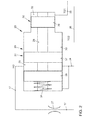
Fig. 1 , - Fig. 3
- in einem schematischen Hydraulikplan die hydraulische Steuervorrichtung mit einem zweiten Druckabbauventil, und
- Fig. 4
- in einer schematischen Detaildarstellung das zweite Druckabbauventil.
- In den
Fig. 1 und3 ist eine hydraulische Steuerungsvorrichtung 1 für eine nicht näher dargestellte Kupplung und/oder für ein nicht näher dargestelltes Getriebe eines Kraftfahrzeuges dargestellt. Die hydraulische Steuerungsvorrichtung 1 ist insbesondere für ein Doppelkupplungsgetriebe ausgebildet und geeignet. - Die hydraulische Steuerungsvorrichtung 1 weist mindestens einen Aktor (auch als "Aktuator" bezeichnenbar) auf. In der Darstellung sind insgesamt sechs Aktoren 2 bis 7 schematisch dargestellt. Der Aktor 2 dient zur Bewegung einer Schalteinrichtung zum Einlegen der Gänge eins und drei. Der Aktor 3 dient zur Betätigung einer weiteren Schalteinrichtung zum Einlegen der Gänge sieben und fünf. Der Aktor 4 dient zur Betätigung einer ersten Kupplung K1 des Doppelkupplungsgetriebes. Der Aktor 5 dient zur Betätigung einer weiteren Schalteinrichtung zum Einlegen der Gänge zwei und vier. Der Aktor 6 dient zur Betätigung einer weiteren Schalteinrichtung zum Einlegen des sechsten Ganges und eines Rückwärtsgangs. Der Aktor 7 dient zur Betätigung einer zweiten Kupplung K2 des Doppelkupplungsgetriebes. Die Aktoren 2 bis 7 sind hydraulisch betätigbar. Die Aktoren 2, 3 beziehungsweise die Aktoren 5, 6 sind als doppelt wirkende Zylinder ausgebildet.
- Zur Versorgung der Aktoren 2 bis 7 mit einem Druckmittel, insbesondere einem Hydrauliköl ist eine Pumpe 8 vorgesehen. Die Pumpe 8 wird von einem Motor 9 angetrieben und pumpt das Druckmittel aus einem Tank 10. Der Tank 10 kann auch als Sumpf bezeichnet werden. Der Motor 9 ist insbesondere als Elektromotor ausgebildet. Die Pumpe 8 kann eine maximale spezifische Förderleistung aufweisen. Die Pumpe 8 kann als Außenzahnradpumpe ausgebildet sein. Die Pumpe 8 fördert das Druckmittel zu einem Filter 11. Parallel zu dem Filter 11 ist ein federbelastetes Rückschlagventil 12 angeordnet.
- Hinter dem Filter 11 und dem Rückschlagventil 12 ist ein Abzweig 13 mit einem Druckbegrenzungsventil 14 angeordnet. Das Druckbegrenzungsventil 14 öffnet, wenn ein Maximaldruck erreicht bzw. überschritten wird. Das Druckbegrenzungsventil 14 ist als federbelastetes Rückschlagventil ausgebildet. Der Abzweig 13 mündet wieder in den Tank 10. Ferner ist hinter dem Filter 11 und dem Rückschlagventil 12 ein weiterer Abzweig 15 angeordnet, wobei der Abzweig 15 über ein weiteres Rückschlagventil 16 in den Hauptdruckkanal 17 mündet.
- Die hydraulische Steuerungsvorrichtung 1 weist ferner einen Druckspeicher 18 auf. Der Druckspeicher 18 ist dem Hauptdruckkanal 17 zugeordnet. Die hydraulische Steuerungsvorrichtung 1 weist ferner einen Druckmesser 19 auf. Der Druckmesser 19 misst den Druck im Hauptdruckkanal 17.
- Die hydraulische Steuerungsvorrichtung 1 weist ferner ein Druckabbauventil 20 (vgl.
Fig. 1 ,2 ) beziehungsweise ein Druckabbauventil 21 (vgl.Fig. 3 und4 ) auf. Das Druckabbauventil 20 beziehungsweise 21 dient dazu, den Speicherdruck des Druckspeichers 18 beziehungsweise den Druck im Hauptdruckkanal 17 abzubauen. - Die eingangs genannten Nachteile sind nun dadurch vermieden, dass mindestens zwei hydraulische Teilsysteme 22, 23 vorgesehen sind, wobei jedes Teilsystem 22, 23 mindestens einen Aktor 2, 3, 4; 5, 6 bzw. 7 aufweist, wobei das Druckabbauventil 20 bzw. 21 mit jedem der Teilsysteme 22, 23 strömungstechnisch verbunden ist und wobei, wenn die Teilsysteme 22, 23 einen Mindestdruck unterschreiten, der im Druckspeicher 18 gespeicherte Druck über das Druckabbauventil 20 bzw. 21 abbaubar ist.
- Dem Teilsystem 22 sind die Aktoren 2, 3, 4 des einen Teilgetriebes und dem anderen Teilsystem 23 sind die Aktoren 5, 6, 7 des anderen Teilgetriebes zugeordnet.
- Den Aktoren 2, 3 ist jeweils ein Gangstellventil GSV1 bzw. GSV2 zugeordnet. Die Gangstellventile GSV1, GSV2 sind dem ersten Teilsystem 22 zugeordnet. Dem Aktor 4 ist ein Kupplungsventil KV1 zugeordnet. Das Kupplungsventil KV1 ist dem ersten Teilsystem 22 zugeordnet. Die Gangstellventile GSV1, GSV2 und das Kupplungsventil KV1 sind als 3/3-Wegeventile ausgebildet.
- In entsprechender Weise ist den Aktoren 5, 6 je ein Gangstellventil GSV3 bzw. GSV4 zugeordnet und dem Aktor 7 ist ein Kupplungsventil KV2 zugeordnet. Die Aktoren 4, 7 zur Betätigung der Kupplung sind einfach wirkend mit Rückhubfeder ausgebildet. Der Hauptkanal 17 verzweigt über zwei Teilgetriebeventile VP1, VP2 in die jeweiligen Teilsysteme 22 bzw. 23. Die Teilgetriebeventile VP1, VP2 sind ebenfalls als 3/3-Wegeventile ausgebildet. Mittels der Teilgetriebeventile VP1, VP2 sind das Teilsystem 22 beziehungsweise das Teilsystem 23 drucklos schaltbar. Sowohl die Teilgetriebeventile VP1 bzw. VP2 als auch die Gangstellventile GSV1, GSV2, GSV3, GSV4 und die Kupplungsventile KV1, KV2 sind über eine Tankleitung 24 mit dem Tank 10 verbunden. Die Gangstellerventile GSV1, GSV2 sowie das Kupplungsventil KV1 sind über einen Teilsystemdruckkanal 25 mit dem Hauptdruckkanal 17 (über das Teilgetriebeventil VP1) bzw. mit dem Druckabbauventil 20 verbindbar. Über einen entsprechenden Teilsystemdruckkanal 26 sind die Gangstellerventile GSV3, GSV4 und das Kupplungsventil KV2 mit dem Hauptdruckkanal 17 (über das Teilgetriebeventil VP2) bzw. mit dem Druckabbauventil 21 verbindbar.
- Das Druckabbauventil 20, 21 ist nun zum einen mit dem Hauptdruckkanal 17 und zum anderen mit der Tankleitung 24 funktional wirksam verbunden. Ferner ist das Druckabbauventil 20, 21 zum einen mit dem Teilsystemdruckkanal 25 und zum anderen mit dem Teilsystemdruckkanal 26 verbunden. Wenn nun der Systemdruck in beiden Teilsystemdruckkanälen 25, 26 unter den Mindestdruck fällt, so nimmt das Druckabbauventil 20, 21 einen Zustand ein, in dem eine Strömungsverbindung zwischen dem Hauptdruckkanal 17 und der Tankleitung 24 besteht. Hierdurch kann der Druck des Druckspeichers 18 über das Druckabbauventil 20, 21 abgebaut werden. Wenn der Systemdruck in zumindest einem der beiden Teilsysteme 22, 23 den Mindestdruck überschreitet, verlagert sich das jeweilige Druckabbauventil 20, 21 in eine Stellung, so dass hier keine Strömungsverbindung zwischen dem Hauptdruckkanal 17 und der Tankleitung 24 besteht.
- Im Folgenden darf auf den Aufbau der Druckabbauventile 20 und 21 anhand der
Fig. 2 und4 näher eingegangen werden. - Die Druckabbauventile 20, 21 sind jeweils über ein Drosselventil 27 mit dem Hauptdruckkanal 17 verbunden. Somit wird einerseits ein schlagartiger Druckabbau verhindert, anderseits nach dem durchgeführten Druckabbau ein Druckaufbau in dem Druckspeicher 18 ermöglicht.
- Das in der
Fig. 2 dargestellte Druckabbauventil 20 weist einen Stufenkolben 28 auf. Der Stufenkolben 28 ist in einem entsprechend gestuften Zylinder 29 geführt. Der Zylinder 29 weist zwei Abschnitte 30, 31 mit unterschiedlichem Durchmesser auf. Der Abschnitt 30 weist einen kleineren Durchmesser als der Abschnitt 31 auf. Der Zylinder 29 und der Stufenkolben 28 weist für jedes Teilsystem 22, 23 einen eigenen Wirkraum 32, 33 auf. Der Teilsystemdruckkanal 25 des ersten Teilsystems 22 beziehungsweise des ersten Teilgetriebes mündet in den ersten Wirkraum 32 und der zweite Teilsystemdruckkanal 26 des zweiten Teilgetriebes beziehungsweise des zweiten Teilsystems 23 mündet in den zweiten Wirkraum 33. - Die Wirkräume 32, 33 sind ringförmig beziehungsweise als Ringräume ausgebildet. Der Stufenkolben 28 ist durch eine Feder 34 vorgespannt. In der nicht dargestellten Grundstellung verschließt der Stufenkolben 28 die entsprechenden Anschlüsse (nicht näher bezeichnet) des Hauptdruckkanals 17 beziehungsweise der Tankleitung 24, so dass das Druckmittel nicht in die Tankleitung 24 aus dem Hauptdruckkanal 17 heraus entweichen kann. In der dargestellten Stellung des Stufenkolbens 28 sind der Hauptdruckkanal 17 und die Tankleitung 24 über einen von dem Stufenkolben 28 begrenzten Blendenraum 35 miteinander verbunden. Der Blendenraum 35 ist ringförmig ausgebildet. Der Blendenraum 35 ist beabstandet zu den Wirkräumen 32, 33 ausgebildet. Der Wirkraum 32 und der Wirkraum 33 sind durch einen ersten Kolbenbereich 36 voneinander getrennt. Der erste Kolbenbereich 36 ist an dem ersten Abschnitt 30 geführt. Der Kolbenbereich 36 ist abdichtend an dem Abschnitt 30 geführt. Der Blendenraum 35 und der Wirkraum 33 sind durch einen zweiten Kolbenbereich 37 voneinander beabstandet. Zwischen dem Blendenraum 35 und der Feder 34 ist ein weiterer Kolbenbereich 38 angeordnet. Die beiden Kolbenbereiche 37, 38 sind abdichtend an dem Abschnitt 31 geführt. In der hier in
Fig. 2 dargestellten Position ist die Verbindung zwischen dem Hauptdruckkanal 17 und der Tankleitung 24 geöffnet. - Im Folgenden darf auf die in
Fig. 4 dargestellte Ausgestaltung des Druckabbauventils 21 näher eingegangen werden: - Das Druckabbauventil 21 weist einen Stufenkolben 39 und einen ebenfalls gestuften Zylinder 40 auf. Der Stufenkolben 39 weist drei Abschnitte 41, 42, 43 jeweils mit unterschiedlichem Durchmesser auf. Der Stufenkolben 39 weist zwei Kolbenbereiche 44, 45 auf, die an den Innendurchmesser des Abschnitts 41 angepasst sind. Zwischen den beiden Kolbenbereichen 44, 45 ist ein Blendenraum 46 ausgebildet. Je nach Stellung des Stufenkolbens 39 verbindet oder sperrt der Blendenraum 46 beziehungsweise die Kolbenbereiche 44, 45 die Verbindung zwischen dem Hauptdruckkanal 17 und der Tankleitung 24. Der Blendenraum 46 ist durch einen Ringraum zwischen den beiden Kolbenbereichen 44, 45 gebildet.
- Der Stufenkolben 39 weist ferner einen Kolbenbereich 47 auf, wobei der Kolbenbereich 47 an den Innendurchmesser des Abschnitts 42 angepasst ist. Durch den Abschnitt 42, den Kolbenbereich 47 und die Stirnseite der Stufe 48 ist ein Wirkraum 49 begrenzt, wobei der Wirkraum 49 funktional wirksam mit dem ersten Teilsystemdruckkanal 25 verbunden ist. Ein Kolbenbereich 50 ist dem Abschnitt 43 mit entsprechend angepasstem Durchmesser zugeordnet. Der Kolbenbereich 50 sowie der Abschnitt 43 und die Stirnseite einer Stufe 51 begrenzen einen zweiten Wirkraum 52, wobei der Wirkraum 52 funktional wirksam mit dem Teilsystemdruckkanal 26 verbunden ist.
- Die Ringflächen an den Stufen 48, 51 sind unterschiedlich groß. Die Differenz der Ringflächen bewirkt bei Druckbeaufschlagung aus den Teilsystemen 22, 23 ebenfalls eine Kraft auf den Stufenkolben 39. Soweit der Druck in einem der beiden Teilsystemdruckkanäle 25, 26 einen Mindestdruck überschreitet, wird die resultierende Kraft aus einem der Wirkräume 49, 52 oder aus beiden Wirkräumen 49, 52 größer als die Federkraft und dies führt zum Verschieben des Stufenkolbens 39 gegen eine Feder 53. Hierdurch wird der Blendenraum 46 derart verschoben, so dass der Kolbenbereich 44 die Verbindung zwischen der Tankleitung 24 und dem Hauptdruckkanal 17 schließt.
- Die Wirkräume 49, 52 können über einen engen Ringspalt miteinander verbunden sein, wodurch ein geringer Ölaustausch bei verschiedenen Druckniveaus in den Teilgetrieben besteht. Dies resultiert hier auch nicht in einer Zunahme der Systemleckage, da die Systemleckage durch die Teilgetriebeventile VP1 und VP2 ausgeglichen wird.
- Im Folgenden darf nochmals Bezug genommen werden auf die
Fig. 1 und3 : - Im Betrieb sind beide Teilgetriebeventile VP1 und VP2 ständig geöffnet. Die Teilgetriebeventile VP1, VP2 schließen entweder, wenn die "Zündung ausgeschaltet ist", oder bei einem Fehler in einem der Teilsysteme 22, 23, wobei hierbei nur das jeweils zugeordnete Teilgetriebeventil VP1 beziehungsweise VP2 schließt. Im Betrieb kann der Druck in den Teilsystemen 22, 23 beziehungsweise in den Teilsystemdruckkanälen 25, 26 varüeren. Der Teilsystemdruck in den Teilsystemdruckkanälen 25, 26 weist jeweils einen bestimmten Druck auf. Das jeweilige Druckabbauventil 20 bzw. 21 ist so eingestellt, dass die Tankleitung 24, auch wenn beispielsweise das erste Teilgetriebe abgeschaltet ist und der Druck im zweiten Teilgetriebe zumindest den Mindestdruck beträgt (oder größer ist), geschlossen bleibt.
- Das Druckabbauventil 20 beziehungsweise 21 kann entweder zweistufig oder dreistufig ausgebildet sein. Die an den Blendenraum 35 beziehungsweise 46 angrenzenden Flächen sind insbesondere fein bearbeitet. In einer sehr kostengünstigen Variante kann die Blende, d. h. dieser Bereich des Druckabbauventils 20 bzw. 21, als ein Kegel- oder Kugelventil ausgeführt werden oder kann der Stufenkolben mit einem solchem Ventil verbunden werden bzw. ein solches Ventil betätigen. Somit ist keine feine Bearbeitung notwendig. Die anderen Abschnitte 30 bzw. 42, 43 können kostengünstig durch O-Ringe abgedichtet werden. Die fein bearbeiteten Flächen sind beim dreistufigen Druckabbauventil 21 kleiner als beim zweistufigen Druckabbauventil 20.
- Die hier vorgestellte mechanische Lösung der Druckabbauventile 20, 21 ist kostengünstig und einfach herzustellen. In alternativer Ausgestaltung ist es denkbar, dass das Druckabbauventil 20, 21 noch zusätzlich elektrisch betätigt wird, um z. B. den Druckabbau bei Bedarf in bestimmten Situationen zu verhindern. Hierbei ist eine elektrische Zuleitung bzw. eine in entsprechende Steueranweisung eines Steuergerätes notwendig.
-
1 hydraulische Steuerungsvorrichtung 2 Aktor 3 Aktor 4 Aktor 5 Aktor 6 Aktor 7 Aktor 8 Pumpe 9 Motor 10 Tank 11 Filter 12 Rückschlagventil 13 Abzweig 14 Druckbegrenzungsventil 15 Abzweig 16 Rückschlagventil 17 Hauptdruckkanal 18 Druckspeicher 19 Druckmesser 20 Druckabbauventil 21 Druckabbauventil 22 Teilsystem 23 Teilsystem 24 Tankleitung 25 Teilsystemdruckkanal 26 Teilsystemdruckkanal 27 Drosselventil 28 Stufenkolben 29 Zylinder 30 Abschnitt 31 Abschnitt 32 Wirkraum 33 Wirkraum 34 Feder 35 Blendenraum 36 Kolbenbereich 37 Kolbenbereich 38 Kolbenbereich 39 Stufenkolben 40 Zylinder 41 Abschnitt 42 Abschnitt 43 Abschnitt 44 Kolbenbereich 45 Kolbenbereich 46 Blendenraum 47 Kolbenbereich 48 Stufe 49 Wirkraum 50 Kolbenbereich 51 Stufe 52 Wirkraum 53 Feder GSV1 Gangstellventil GSV2 Gangstellventil KV1 Kupplungsventil KV2 Kupplungsventil VP1 Teilgetriebeventil VP2 Teilgetriebeventil
Claims (10)
- Hydraulische Steuerungsvorrichtung (1) für eine Kupplung und/oder für ein Getriebe eines Kraftfahrzeuges, vorzugsweise für ein Doppelkupplungsgetriebe, mit mindestens einem Aktor (2, 3, 4, 5, 6, 7), mit einem Druckspeicher (18) und mit einem Druckabbauventil (20, 21), wobei der im Druckspeicher (18) gespeicherte Druck über das Druckabbauventil (20, 21) abbaubar ist, dadurch gekennzeichnet, dass mindestens zwei hydraulische Teilsysteme (22, 23) vorgesehen sind, wobei jedes Teilsystem (22, 23) mindestens einen Aktor (2, 3, 4; 5, 6, 7) aufweist, wobei das Druckabbauventil (20, 21) mit jedem der Teilsysteme (22, 23) strömungstechnisch verbunden ist und wobei, wenn die Teilsysteme (22, 23) einen Mindestdruck unterschreiten, der im Druckspeicher (18) gespeicherte Druck über das Druckabbauventil (20, 21) abbaubar ist.
- Hydraulische Steuerungsvorrichtung nach Anspruch 1, dadurch gekennzeichnet, dass mit dem Druckabbauventil (20, 21) eine Strömungsverbindung zwischen einem Hauptdruckkanal (17) mit dem Druckspeicher (18) zu einer Tankleitung (24) verschließbar und öffenbar ist.
- Hydraulische Steuerungsvorrichtung nach Anspruch 1 oder 2, dadurch gekennzeichnet, dass das Druckabbauventil (20, 21) einen Stufenkolben (28, 39) aufweist bzw. als Stufenkolben-Ventil ausgeführt ist, wobei der Stufenkolben in einem entsprechenden Zylinder (29, 40) geführt ist, wobei der Stufenkolben mehrere, den Teilsystemen (22, 23) zugeordnete Wirkräume (32, 33; 49, 52) aufweist und wobei die Wirkräume (32, 33; 49, 52) über den Teilsystemen (22, 23) zugeordnete Teilsystemdruckkanäle (25, 26) druckbeaufschlagbar sind.
- Hydraulische Steuervorrichtung nach Anspruch 3, dadurch gekennzeichnet, dass der Stufenkolben (28, 39) federbeaufschlagt ist, wobei der Stufenkolben (28, 39) durch die Federkraft in eine Position verstellt wird, in der die Verbindung zwischen dem Hauptdruckkanal (17) und der Tankleitung (24) geöffnet ist.
- Hydraulische Steuervorrichtung nach Anspruch 4, dadurch gekennzeichnet, dass die durch den Mindestdruck in mindestens einem der Teilsysteme (22, 23) im Druckabbauventil (20, 21) wirksame bzw. resultierende Kraft größer als die Federkraft ist.
- Hydraulische Steuerungsvorrichtung nach einem der vorstehenden Ansprüche, dadurch gekennzeichnet, dass jedes der Teilsysteme (22, 23) über ein Teilgetriebeventil (VP1, VP2) von einem Hauptdruckkanal (17) trennbar und/oder mit dem Hauptdruckkanal (17) strömungstechnisch verbindbar ist.
- Hydraulische Steuerungsvorrichtung nach einem der vorstehenden Ansprüche, dadurch gekennzeichnet, dass der Stufenkolben (28) und der entsprechende Zylinder (40) zweistufig ausgebildet ist.
- Hydraulische Steuerungsvorrichtung nach einem der vorstehenden Ansprüche, dadurch gekennzeichnet, dass der Stufenkolben (39) und der entsprechende Zylinder (40) dreistufig ausgebildet ist.
- Hydraulische Steuerungsvorrichtung nach einem der vorstehenden Ansprüche, dadurch gekennzeichnet, dass die strömungstechnische Verbindung zwischen dem Druckabbauventil (20, 21) und dem Druckspeicher (18) oder die strömungstechnische Verbindung zwischen dem Druckabbauventil (20, 21) und der Tankleitung (24) gedrosselt ist.
- Hydraulische Steuerungsvorrichtung nach dem Anspruch 9, dadurch gekennzeichnet, dass ein Drosselventil (27) in dem Hauptdruckkanal (17) oder in dem Druckabbauventil (20, 21) angeordnet ist.
Applications Claiming Priority (1)
| Application Number | Priority Date | Filing Date | Title |
|---|---|---|---|
| DE102012007124A DE102012007124A1 (de) | 2012-04-07 | 2012-04-07 | Hydraulische Steuerungsvorrichtung |
Publications (3)
| Publication Number | Publication Date |
|---|---|
| EP2647883A2 true EP2647883A2 (de) | 2013-10-09 |
| EP2647883A3 EP2647883A3 (de) | 2017-09-13 |
| EP2647883B1 EP2647883B1 (de) | 2019-08-21 |
Family
ID=48044591
Family Applications (1)
| Application Number | Title | Priority Date | Filing Date |
|---|---|---|---|
| EP13160813.5A Active EP2647883B1 (de) | 2012-04-07 | 2013-03-25 | Hydraulische Steuerungsvorrichtung |
Country Status (2)
| Country | Link |
|---|---|
| EP (1) | EP2647883B1 (de) |
| DE (1) | DE102012007124A1 (de) |
Cited By (3)
| Publication number | Priority date | Publication date | Assignee | Title |
|---|---|---|---|---|
| CN104595255A (zh) * | 2014-12-30 | 2015-05-06 | 吉林大学 | 游梁式抽油机液压辅助动力节能系统 |
| WO2016066515A1 (de) * | 2014-10-27 | 2016-05-06 | Avl Commercial Driveline & Tractor Engineering Gmbh | Hydraulikkreislauf und verfahren zum steuern eines hydraulikkreislaufes |
| WO2017186710A1 (de) * | 2016-04-26 | 2017-11-02 | Avl Commercial Driveline & Tractor Engineering Gmbh | Hydraulikkreislauf, drehmomentübertragungsvorrichtung mit einem hydraulikkreislauf, verfahren zum betrieb eines hydraulikkreislaufs |
Families Citing this family (1)
| Publication number | Priority date | Publication date | Assignee | Title |
|---|---|---|---|---|
| DE102019211854A1 (de) * | 2019-08-07 | 2021-02-11 | Zf Friedrichshafen Ag | Ölversorgungssystem für ein Automatikgetriebe |
Family Cites Families (7)
| Publication number | Priority date | Publication date | Assignee | Title |
|---|---|---|---|---|
| US3353495A (en) | 1966-03-02 | 1967-11-21 | Caterpillar Tractor Co | Automatic accumulator bleed means |
| US3991570A (en) | 1975-09-29 | 1976-11-16 | Western Fluid Power Corporation | Hydraulic accumulator pressure release valve and system |
| DD126317A1 (de) * | 1976-06-28 | 1977-07-06 | ||
| AU2002218265A1 (en) * | 2000-11-17 | 2002-05-27 | Mannesmann Sachs Ag | Clutch system |
| WO2007124790A1 (de) * | 2006-04-26 | 2007-11-08 | Borgwarner.Inc | Hydraulische anordnung für eine kupplung eines kraftfahrzeuges und verfahren zum betrieb |
| JP4420112B2 (ja) * | 2008-01-15 | 2010-02-24 | トヨタ自動車株式会社 | 車両用同期噛合式変速機の油圧制御回路 |
| DE102008049739B4 (de) * | 2008-09-30 | 2020-07-23 | Ipgate Ag | Zentrale Druckversorgung für Nebenantriebe |
-
2012
- 2012-04-07 DE DE102012007124A patent/DE102012007124A1/de not_active Withdrawn
-
2013
- 2013-03-25 EP EP13160813.5A patent/EP2647883B1/de active Active
Cited By (4)
| Publication number | Priority date | Publication date | Assignee | Title |
|---|---|---|---|---|
| WO2016066515A1 (de) * | 2014-10-27 | 2016-05-06 | Avl Commercial Driveline & Tractor Engineering Gmbh | Hydraulikkreislauf und verfahren zum steuern eines hydraulikkreislaufes |
| CN104595255A (zh) * | 2014-12-30 | 2015-05-06 | 吉林大学 | 游梁式抽油机液压辅助动力节能系统 |
| WO2017186710A1 (de) * | 2016-04-26 | 2017-11-02 | Avl Commercial Driveline & Tractor Engineering Gmbh | Hydraulikkreislauf, drehmomentübertragungsvorrichtung mit einem hydraulikkreislauf, verfahren zum betrieb eines hydraulikkreislaufs |
| US11015707B2 (en) | 2016-04-26 | 2021-05-25 | Avl Commercial Driveline & Tractor Engineering Gmbh | Hydraulic circuit, torque transmission device having a hydraulic circuit, and method for operating a hydraulic circuit |
Also Published As
| Publication number | Publication date |
|---|---|
| DE102012007124A1 (de) | 2013-10-10 |
| EP2647883B1 (de) | 2019-08-21 |
| EP2647883A3 (de) | 2017-09-13 |
Similar Documents
| Publication | Publication Date | Title |
|---|---|---|
| DE102012200202B4 (de) | Hydraulische Schaltvorrichtung für ein Automatikgetriebe | |
| EP1596104B1 (de) | Vorrichtung zum Ansteuern einer Mehrzahl von hydraulischen Schaltzylindern sowie Hydraulikversorgungssystem für ein Doppelkupplungsgetriebe | |
| EP1994310A1 (de) | Hydraulische steuerung für ein doppelkupplungsgetriebe | |
| DE102011104530A1 (de) | Hydraulische Stellanordnung | |
| DE102013212947A1 (de) | Hydraulische Steuerungseinrichtung für ein Automatikgetriebe | |
| EP1469235A1 (de) | Hydraulisches Steuer- und Regelsystem sowie Verfahren zum Einstellen von hydraulischen Druckniveaus | |
| DE102005019516A1 (de) | Vorrichtung zum Ansteuern einer Mehrzahl von hydraulischen Schaltzylindern sowie Hydraulikversorgungssystem für ein Doppelkupplungsgetriebe | |
| DE10338355A1 (de) | Doppelkupplungsgetriebe mit Zustandshaltefunktion | |
| DE102013221035A1 (de) | Hydraulische Steuerungsvorrichtung für ein Automatikgetriebe | |
| DE102011085255A1 (de) | Zapfwellengetriebe | |
| EP3093532B1 (de) | Hydrauliksystem eines kraftfahrzeugs | |
| WO2015036076A1 (de) | Steuervorrichtung zum wahlweisen fluidischen verbinden und trennen von fluid-anschlussstellen | |
| EP2647883B1 (de) | Hydraulische Steuerungsvorrichtung | |
| DE102013001928A1 (de) | Kraftfahrzeuggetriebevorrichtung mit einem Hydrauliksystem | |
| EP1903238B1 (de) | Hydraulisches System | |
| DE102012022086B4 (de) | Hydraulische Steuerungsvorrichtung | |
| EP1635092B1 (de) | Hydraulische Steuerungsvorrichtung für eine Schaltgabel in einem Schaltgetriebe | |
| EP2929217B1 (de) | Vorrichtung zur steuerung des betriebs eines mittels eines hydromotors antreibbaren lüfters einer kühleinrichtung | |
| DE102009038377A1 (de) | Hydraulikanordnung | |
| DE2212679B2 (de) | Hydraulische Schaltvorrichtung für Lastschaltgetriebe mit Sicherung gegen Fehlschaltungen | |
| DE102020004389A1 (de) | Hydrauliksystem für ein Doppelkupplungsgetriebe | |
| DE102005008661A1 (de) | Notöffnung eines hydraulischen Systems für eine Doppelkupplung | |
| DE102018108712A1 (de) | Fluidanordnung | |
| DE102010038078B4 (de) | Hydraulische Parksperre und Verfahren zum Schalten einer solchen | |
| DE102017219645A1 (de) | Ventil, Hydrauliksystem und Kraftfahrzeuggetriebe |
Legal Events
| Date | Code | Title | Description |
|---|---|---|---|
| PUAI | Public reference made under article 153(3) epc to a published international application that has entered the european phase |
Free format text: ORIGINAL CODE: 0009012 |
|
| AK | Designated contracting states |
Kind code of ref document: A2 Designated state(s): AL AT BE BG CH CY CZ DE DK EE ES FI FR GB GR HR HU IE IS IT LI LT LU LV MC MK MT NL NO PL PT RO RS SE SI SK SM TR |
|
| AX | Request for extension of the european patent |
Extension state: BA ME |
|
| PUAL | Search report despatched |
Free format text: ORIGINAL CODE: 0009013 |
|
| AK | Designated contracting states |
Kind code of ref document: A3 Designated state(s): AL AT BE BG CH CY CZ DE DK EE ES FI FR GB GR HR HU IE IS IT LI LT LU LV MC MK MT NL NO PL PT RO RS SE SI SK SM TR |
|
| AX | Request for extension of the european patent |
Extension state: BA ME |
|
| RIC1 | Information provided on ipc code assigned before grant |
Ipc: F15B 1/027 20060101ALI20170809BHEP Ipc: F16H 61/00 20060101AFI20170809BHEP |
|
| STAA | Information on the status of an ep patent application or granted ep patent |
Free format text: STATUS: REQUEST FOR EXAMINATION WAS MADE |
|
| 17P | Request for examination filed |
Effective date: 20180313 |
|
| RBV | Designated contracting states (corrected) |
Designated state(s): AL AT BE BG CH CY CZ DE DK EE ES FI FR GB GR HR HU IE IS IT LI LT LU LV MC MK MT NL NO PL PT RO RS SE SI SK SM TR |
|
| GRAP | Despatch of communication of intention to grant a patent |
Free format text: ORIGINAL CODE: EPIDOSNIGR1 |
|
| STAA | Information on the status of an ep patent application or granted ep patent |
Free format text: STATUS: GRANT OF PATENT IS INTENDED |
|
| INTG | Intention to grant announced |
Effective date: 20190403 |
|
| GRAS | Grant fee paid |
Free format text: ORIGINAL CODE: EPIDOSNIGR3 |
|
| GRAA | (expected) grant |
Free format text: ORIGINAL CODE: 0009210 |
|
| STAA | Information on the status of an ep patent application or granted ep patent |
Free format text: STATUS: THE PATENT HAS BEEN GRANTED |
|
| AK | Designated contracting states |
Kind code of ref document: B1 Designated state(s): AL AT BE BG CH CY CZ DE DK EE ES FI FR GB GR HR HU IE IS IT LI LT LU LV MC MK MT NL NO PL PT RO RS SE SI SK SM TR |
|
| REG | Reference to a national code |
Ref country code: GB Ref legal event code: FG4D Free format text: NOT ENGLISH |
|
| REG | Reference to a national code |
Ref country code: CH Ref legal event code: EP |
|
| REG | Reference to a national code |
Ref country code: DE Ref legal event code: R096 Ref document number: 502013013393 Country of ref document: DE |
|
| REG | Reference to a national code |
Ref country code: AT Ref legal event code: REF Ref document number: 1170136 Country of ref document: AT Kind code of ref document: T Effective date: 20190915 |
|
| REG | Reference to a national code |
Ref country code: IE Ref legal event code: FG4D Free format text: LANGUAGE OF EP DOCUMENT: GERMAN |
|
| REG | Reference to a national code |
Ref country code: LT Ref legal event code: MG4D |
|
| REG | Reference to a national code |
Ref country code: NL Ref legal event code: MP Effective date: 20190821 |
|
| PG25 | Lapsed in a contracting state [announced via postgrant information from national office to epo] |
Ref country code: SE Free format text: LAPSE BECAUSE OF FAILURE TO SUBMIT A TRANSLATION OF THE DESCRIPTION OR TO PAY THE FEE WITHIN THE PRESCRIBED TIME-LIMIT Effective date: 20190821 Ref country code: BG Free format text: LAPSE BECAUSE OF FAILURE TO SUBMIT A TRANSLATION OF THE DESCRIPTION OR TO PAY THE FEE WITHIN THE PRESCRIBED TIME-LIMIT Effective date: 20191121 Ref country code: NO Free format text: LAPSE BECAUSE OF FAILURE TO SUBMIT A TRANSLATION OF THE DESCRIPTION OR TO PAY THE FEE WITHIN THE PRESCRIBED TIME-LIMIT Effective date: 20191121 Ref country code: PT Free format text: LAPSE BECAUSE OF FAILURE TO SUBMIT A TRANSLATION OF THE DESCRIPTION OR TO PAY THE FEE WITHIN THE PRESCRIBED TIME-LIMIT Effective date: 20191223 Ref country code: HR Free format text: LAPSE BECAUSE OF FAILURE TO SUBMIT A TRANSLATION OF THE DESCRIPTION OR TO PAY THE FEE WITHIN THE PRESCRIBED TIME-LIMIT Effective date: 20190821 Ref country code: LT Free format text: LAPSE BECAUSE OF FAILURE TO SUBMIT A TRANSLATION OF THE DESCRIPTION OR TO PAY THE FEE WITHIN THE PRESCRIBED TIME-LIMIT Effective date: 20190821 Ref country code: NL Free format text: LAPSE BECAUSE OF FAILURE TO SUBMIT A TRANSLATION OF THE DESCRIPTION OR TO PAY THE FEE WITHIN THE PRESCRIBED TIME-LIMIT Effective date: 20190821 Ref country code: FI Free format text: LAPSE BECAUSE OF FAILURE TO SUBMIT A TRANSLATION OF THE DESCRIPTION OR TO PAY THE FEE WITHIN THE PRESCRIBED TIME-LIMIT Effective date: 20190821 |
|
| PG25 | Lapsed in a contracting state [announced via postgrant information from national office to epo] |
Ref country code: LV Free format text: LAPSE BECAUSE OF FAILURE TO SUBMIT A TRANSLATION OF THE DESCRIPTION OR TO PAY THE FEE WITHIN THE PRESCRIBED TIME-LIMIT Effective date: 20190821 Ref country code: RS Free format text: LAPSE BECAUSE OF FAILURE TO SUBMIT A TRANSLATION OF THE DESCRIPTION OR TO PAY THE FEE WITHIN THE PRESCRIBED TIME-LIMIT Effective date: 20190821 Ref country code: GR Free format text: LAPSE BECAUSE OF FAILURE TO SUBMIT A TRANSLATION OF THE DESCRIPTION OR TO PAY THE FEE WITHIN THE PRESCRIBED TIME-LIMIT Effective date: 20191122 Ref country code: ES Free format text: LAPSE BECAUSE OF FAILURE TO SUBMIT A TRANSLATION OF THE DESCRIPTION OR TO PAY THE FEE WITHIN THE PRESCRIBED TIME-LIMIT Effective date: 20190821 Ref country code: IS Free format text: LAPSE BECAUSE OF FAILURE TO SUBMIT A TRANSLATION OF THE DESCRIPTION OR TO PAY THE FEE WITHIN THE PRESCRIBED TIME-LIMIT Effective date: 20191221 Ref country code: AL Free format text: LAPSE BECAUSE OF FAILURE TO SUBMIT A TRANSLATION OF THE DESCRIPTION OR TO PAY THE FEE WITHIN THE PRESCRIBED TIME-LIMIT Effective date: 20190821 |
|
| PG25 | Lapsed in a contracting state [announced via postgrant information from national office to epo] |
Ref country code: TR Free format text: LAPSE BECAUSE OF FAILURE TO SUBMIT A TRANSLATION OF THE DESCRIPTION OR TO PAY THE FEE WITHIN THE PRESCRIBED TIME-LIMIT Effective date: 20190821 |
|
| PG25 | Lapsed in a contracting state [announced via postgrant information from national office to epo] |
Ref country code: DK Free format text: LAPSE BECAUSE OF FAILURE TO SUBMIT A TRANSLATION OF THE DESCRIPTION OR TO PAY THE FEE WITHIN THE PRESCRIBED TIME-LIMIT Effective date: 20190821 Ref country code: EE Free format text: LAPSE BECAUSE OF FAILURE TO SUBMIT A TRANSLATION OF THE DESCRIPTION OR TO PAY THE FEE WITHIN THE PRESCRIBED TIME-LIMIT Effective date: 20190821 Ref country code: IT Free format text: LAPSE BECAUSE OF FAILURE TO SUBMIT A TRANSLATION OF THE DESCRIPTION OR TO PAY THE FEE WITHIN THE PRESCRIBED TIME-LIMIT Effective date: 20190821 Ref country code: RO Free format text: LAPSE BECAUSE OF FAILURE TO SUBMIT A TRANSLATION OF THE DESCRIPTION OR TO PAY THE FEE WITHIN THE PRESCRIBED TIME-LIMIT Effective date: 20190821 Ref country code: PL Free format text: LAPSE BECAUSE OF FAILURE TO SUBMIT A TRANSLATION OF THE DESCRIPTION OR TO PAY THE FEE WITHIN THE PRESCRIBED TIME-LIMIT Effective date: 20190821 |
|
| PG25 | Lapsed in a contracting state [announced via postgrant information from national office to epo] |
Ref country code: SK Free format text: LAPSE BECAUSE OF FAILURE TO SUBMIT A TRANSLATION OF THE DESCRIPTION OR TO PAY THE FEE WITHIN THE PRESCRIBED TIME-LIMIT Effective date: 20190821 Ref country code: IS Free format text: LAPSE BECAUSE OF FAILURE TO SUBMIT A TRANSLATION OF THE DESCRIPTION OR TO PAY THE FEE WITHIN THE PRESCRIBED TIME-LIMIT Effective date: 20200224 Ref country code: CZ Free format text: LAPSE BECAUSE OF FAILURE TO SUBMIT A TRANSLATION OF THE DESCRIPTION OR TO PAY THE FEE WITHIN THE PRESCRIBED TIME-LIMIT Effective date: 20190821 Ref country code: SM Free format text: LAPSE BECAUSE OF FAILURE TO SUBMIT A TRANSLATION OF THE DESCRIPTION OR TO PAY THE FEE WITHIN THE PRESCRIBED TIME-LIMIT Effective date: 20190821 |
|
| REG | Reference to a national code |
Ref country code: DE Ref legal event code: R097 Ref document number: 502013013393 Country of ref document: DE |
|
| PLBE | No opposition filed within time limit |
Free format text: ORIGINAL CODE: 0009261 |
|
| STAA | Information on the status of an ep patent application or granted ep patent |
Free format text: STATUS: NO OPPOSITION FILED WITHIN TIME LIMIT |
|
| PG2D | Information on lapse in contracting state deleted |
Ref country code: IS |
|
| 26N | No opposition filed |
Effective date: 20200603 |
|
| PG25 | Lapsed in a contracting state [announced via postgrant information from national office to epo] |
Ref country code: SI Free format text: LAPSE BECAUSE OF FAILURE TO SUBMIT A TRANSLATION OF THE DESCRIPTION OR TO PAY THE FEE WITHIN THE PRESCRIBED TIME-LIMIT Effective date: 20190821 |
|
| PG25 | Lapsed in a contracting state [announced via postgrant information from national office to epo] |
Ref country code: MC Free format text: LAPSE BECAUSE OF FAILURE TO SUBMIT A TRANSLATION OF THE DESCRIPTION OR TO PAY THE FEE WITHIN THE PRESCRIBED TIME-LIMIT Effective date: 20190821 |
|
| REG | Reference to a national code |
Ref country code: CH Ref legal event code: PL |
|
| REG | Reference to a national code |
Ref country code: BE Ref legal event code: MM Effective date: 20200331 |
|
| PG25 | Lapsed in a contracting state [announced via postgrant information from national office to epo] |
Ref country code: LU Free format text: LAPSE BECAUSE OF NON-PAYMENT OF DUE FEES Effective date: 20200325 |
|
| PG25 | Lapsed in a contracting state [announced via postgrant information from national office to epo] |
Ref country code: FR Free format text: LAPSE BECAUSE OF NON-PAYMENT OF DUE FEES Effective date: 20200331 Ref country code: IE Free format text: LAPSE BECAUSE OF NON-PAYMENT OF DUE FEES Effective date: 20200325 Ref country code: CH Free format text: LAPSE BECAUSE OF NON-PAYMENT OF DUE FEES Effective date: 20200331 Ref country code: LI Free format text: LAPSE BECAUSE OF NON-PAYMENT OF DUE FEES Effective date: 20200331 |
|
| PG25 | Lapsed in a contracting state [announced via postgrant information from national office to epo] |
Ref country code: BE Free format text: LAPSE BECAUSE OF NON-PAYMENT OF DUE FEES Effective date: 20200331 |
|
| GBPC | Gb: european patent ceased through non-payment of renewal fee |
Effective date: 20200325 |
|
| PG25 | Lapsed in a contracting state [announced via postgrant information from national office to epo] |
Ref country code: GB Free format text: LAPSE BECAUSE OF NON-PAYMENT OF DUE FEES Effective date: 20200325 |
|
| REG | Reference to a national code |
Ref country code: AT Ref legal event code: MM01 Ref document number: 1170136 Country of ref document: AT Kind code of ref document: T Effective date: 20200325 |
|
| PG25 | Lapsed in a contracting state [announced via postgrant information from national office to epo] |
Ref country code: AT Free format text: LAPSE BECAUSE OF NON-PAYMENT OF DUE FEES Effective date: 20200325 |
|
| PG25 | Lapsed in a contracting state [announced via postgrant information from national office to epo] |
Ref country code: MT Free format text: LAPSE BECAUSE OF FAILURE TO SUBMIT A TRANSLATION OF THE DESCRIPTION OR TO PAY THE FEE WITHIN THE PRESCRIBED TIME-LIMIT Effective date: 20190821 Ref country code: CY Free format text: LAPSE BECAUSE OF FAILURE TO SUBMIT A TRANSLATION OF THE DESCRIPTION OR TO PAY THE FEE WITHIN THE PRESCRIBED TIME-LIMIT Effective date: 20190821 |
|
| PG25 | Lapsed in a contracting state [announced via postgrant information from national office to epo] |
Ref country code: MK Free format text: LAPSE BECAUSE OF FAILURE TO SUBMIT A TRANSLATION OF THE DESCRIPTION OR TO PAY THE FEE WITHIN THE PRESCRIBED TIME-LIMIT Effective date: 20190821 |
|
| P01 | Opt-out of the competence of the unified patent court (upc) registered |
Effective date: 20230523 |
|
| PGFP | Annual fee paid to national office [announced via postgrant information from national office to epo] |
Ref country code: DE Payment date: 20240331 Year of fee payment: 12 |