EP2647533A2 - Automatische Kabelverspannungsvorrichtung für Feststellbremsen sowie Feststellbremse mit der automatischen Verspannungsvorrichtung - Google Patents
Automatische Kabelverspannungsvorrichtung für Feststellbremsen sowie Feststellbremse mit der automatischen Verspannungsvorrichtung Download PDFInfo
- Publication number
- EP2647533A2 EP2647533A2 EP13382076.1A EP13382076A EP2647533A2 EP 2647533 A2 EP2647533 A2 EP 2647533A2 EP 13382076 A EP13382076 A EP 13382076A EP 2647533 A2 EP2647533 A2 EP 2647533A2
- Authority
- EP
- European Patent Office
- Prior art keywords
- regulating element
- support
- tensioning device
- stop
- regulating
- Prior art date
- Legal status (The legal status is an assumption and is not a legal conclusion. Google has not performed a legal analysis and makes no representation as to the accuracy of the status listed.)
- Withdrawn
Links
- 230000001105 regulatory effect Effects 0.000 claims abstract description 152
- 230000000903 blocking effect Effects 0.000 claims description 19
- 238000006243 chemical reaction Methods 0.000 description 5
- 230000009471 action Effects 0.000 description 2
- 230000002860 competitive effect Effects 0.000 description 1
- 230000008878 coupling Effects 0.000 description 1
- 238000010168 coupling process Methods 0.000 description 1
- 238000005859 coupling reaction Methods 0.000 description 1
- 230000002427 irreversible effect Effects 0.000 description 1
- 238000004519 manufacturing process Methods 0.000 description 1
- 230000007246 mechanism Effects 0.000 description 1
- 238000000034 method Methods 0.000 description 1
- 230000008569 process Effects 0.000 description 1
- 230000009467 reduction Effects 0.000 description 1
- 230000007704 transition Effects 0.000 description 1
Images


Classifications
-
- F—MECHANICAL ENGINEERING; LIGHTING; HEATING; WEAPONS; BLASTING
- F16—ENGINEERING ELEMENTS AND UNITS; GENERAL MEASURES FOR PRODUCING AND MAINTAINING EFFECTIVE FUNCTIONING OF MACHINES OR INSTALLATIONS; THERMAL INSULATION IN GENERAL
- F16C—SHAFTS; FLEXIBLE SHAFTS; ELEMENTS OR CRANKSHAFT MECHANISMS; ROTARY BODIES OTHER THAN GEARING ELEMENTS; BEARINGS
- F16C1/00—Flexible shafts; Mechanical means for transmitting movement in a flexible sheathing
- F16C1/10—Means for transmitting linear movement in a flexible sheathing, e.g. "Bowden-mechanisms"
- F16C1/22—Adjusting; Compensating length
-
- B—PERFORMING OPERATIONS; TRANSPORTING
- B60—VEHICLES IN GENERAL
- B60T—VEHICLE BRAKE CONTROL SYSTEMS OR PARTS THEREOF; BRAKE CONTROL SYSTEMS OR PARTS THEREOF, IN GENERAL; ARRANGEMENT OF BRAKING ELEMENTS ON VEHICLES IN GENERAL; PORTABLE DEVICES FOR PREVENTING UNWANTED MOVEMENT OF VEHICLES; VEHICLE MODIFICATIONS TO FACILITATE COOLING OF BRAKES
- B60T7/00—Brake-action initiating means
- B60T7/02—Brake-action initiating means for personal initiation
- B60T7/08—Brake-action initiating means for personal initiation hand actuated
- B60T7/10—Disposition of hand control
- B60T7/108—Disposition of hand control with mechanisms to take up slack in the linkage to the brakes
-
- B—PERFORMING OPERATIONS; TRANSPORTING
- B60—VEHICLES IN GENERAL
- B60T—VEHICLE BRAKE CONTROL SYSTEMS OR PARTS THEREOF; BRAKE CONTROL SYSTEMS OR PARTS THEREOF, IN GENERAL; ARRANGEMENT OF BRAKING ELEMENTS ON VEHICLES IN GENERAL; PORTABLE DEVICES FOR PREVENTING UNWANTED MOVEMENT OF VEHICLES; VEHICLE MODIFICATIONS TO FACILITATE COOLING OF BRAKES
- B60T11/00—Transmitting braking action from initiating means to ultimate brake actuator without power assistance or drive or where such assistance or drive is irrelevant
- B60T11/04—Transmitting braking action from initiating means to ultimate brake actuator without power assistance or drive or where such assistance or drive is irrelevant transmitting mechanically
- B60T11/046—Using cables
-
- Y—GENERAL TAGGING OF NEW TECHNOLOGICAL DEVELOPMENTS; GENERAL TAGGING OF CROSS-SECTIONAL TECHNOLOGIES SPANNING OVER SEVERAL SECTIONS OF THE IPC; TECHNICAL SUBJECTS COVERED BY FORMER USPC CROSS-REFERENCE ART COLLECTIONS [XRACs] AND DIGESTS
- Y10—TECHNICAL SUBJECTS COVERED BY FORMER USPC
- Y10T—TECHNICAL SUBJECTS COVERED BY FORMER US CLASSIFICATION
- Y10T74/00—Machine element or mechanism
- Y10T74/20—Control lever and linkage systems
- Y10T74/20396—Hand operated
- Y10T74/20402—Flexible transmitter [e.g., Bowden cable]
- Y10T74/20408—Constant tension sustaining
Definitions
- the present invention is related to an automatic cable tensioning device particularly suitable for parking brakes. On the other hand, it is also related to a parking brake comprising the automatic tensioning device.
- Cable tensioning devices suitable for parking brakes intended for maintaining the tension of the brake cables that will be connected to the brakes of the corresponding motor vehicle are known.
- the devices comprise automatically adjustable regulating means for adjusting the tension such that if the brake cable loses tension in a rest position of the parking brake, the automatic tensioning device acts on the cable tensioning it, if necessary.
- US2009/0314122 describes a parking brake comprising a tensioning device.
- the tensioning device comprises a toothed bar which is fixed at one end to a brake cable of the motor vehicle, elastic means acting on the toothed bar moving it when the cable loses tension, and a pawl which engages the toothed bar preventing the toothed bar from moving in a direction that reduces tension in the brake cable.
- ES2160537B1 describes a tensioning device comprising a toothed bar having a circular section which is fixed at one end to a brake cable of the motor vehicle, elastic means acting on the toothed bar moving it when the cable loses tension, two wedged side parts and a support housing the two wedged side parts therein.
- the wedged parts comprise teeth, being arranged surrounding the toothed bar.
- the elastic means act on the wedged side parts blocking the movement of the bar towards the direction opposite the elastic means.
- WO2009/127047A1 describes a self-adjusting device including a toothed bar which is fixed at one end to a brake cable of the motor vehicle, elastic means acting on the toothed bar moving it when the cable loses tension, an engagement element engaging the bar blocking the movement of the bar in a block position and releasing the bar in an unblock position, allowing cable tension adjustment.
- the elastic means act on the engagement element so that it engages the bar and blocks the axial movement of said bar.
- the object of the invention is to provide an automatic cable tensioning device suitable for parking brakes and a parking brake with the automatic tensioning device according to the claims.
- the automatic cable tensioning device comprises a support suitable for being coupled to a parking brake lever, a first regulating element suitable for being coupled to the cable, elastic means suitable for regulating the tension of the cable which act on the first regulating element, a second regulating element which is housed in the support being moved with respect to the support between a rest position where a relative movement between both regulating elements occurs for tensioning the cable and a block position where the second regulating element blocks the relative movement between both regulating elements.
- the first regulating element comprises an outer thread traversing the second regulating element
- the second regulating element comprises an inner thread and a first contact surface.
- the inner thread cooperates with the outer thread of the first regulating element to move, from the rest position, the first regulating element with respect to the second regulating element towards the elastic means by means of rotation of the second regulating element when the first contact surface of the second regulating element is in contact with a first contact surface of the support.
- the stop of the second regulating element blocks the rotation of the second regulating element with respect to the first regulating element in the block position of the automatic tensioning device. The first regulating element is thus prevented from moving with respect to the second regulating element, the tension of the corresponding brake cable being reduced.
- the self-tensioning device obtained is a compact device that is easy to maintain and assemble, and optimized in terms of the number of necessary elements. Additionally, the elements integrated in the device are less complex and easy to produce, so the cost of the assembly is also lower and more competitive compared with other known systems.
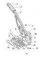
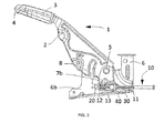
- FIG. 1 to 3 shows a parking brake 1 suitable for motor vehicles comprising an automatic cable tensioning device 10 according to the invention.
- the parking brake 1 comprises a support 6 suitable for being fixed to the motor vehicle, a lever 2 rotatably coupled to the support 6, and the automatic cable tensioning device 10 suitable for automatically tensioning a cable, not depicted, that can be connected to the brakes of the motor vehicle.
- the support 6 comprises side walls 6a,6b arranged substantially parallel to one another and as continuations of a base 6c, the lever 2 being coupled to the side walls 6a,6b of the support 6 through a shaft 5.
- the parking brake 1 comprises an auxiliary support 7 comprising walls 7a,7b arranged substantially parallel to one another, which are integrally attached to one another and to the lever 2 through the shaft 5.
- the automatic cable tensioning device 10 is arranged between the two walls 7a,7b of the auxiliary support 7, coupled to said walls 7a,7b.
- each wall 7a,7b of the auxiliary support 7 comprises a closed groove 8 necessary for assembling and positioning said automatic tensioning device 10 on the auxiliary support 7.
- the lever 2 is coupled to the shaft 5 at one end and comprises at the other end a grip 3 through which the driver grasps the parking brake 1 and an unblocking button 4 which the driver must press to go from a block position, also referred to as an activated parking brake position, shown in Figures 1 to 3 , to a rest position in which the parking brake 1 is not activated.
- a block position also referred to as an activated parking brake position, shown in Figures 1 to 3
- the mechanisms which allow maintaining the lever 2 in the block position are known in the state of the art so they will not be described in this description.
- the automatic tensioning device 10 comprises a support 20,40 suitable for being coupled to the auxiliary support 6, a first regulating element 11 suitable for being coupled to the brake cable, elastic means 13 suitable for adjusting the tension of the cable in the rest position, and a second regulating element 30 which is housed in the support 20,40 and moved with respect to said support 20,40 between the rest position and the block position. Therefore, in the rest position, a relative movement between both regulating elements 11,30 occurs for tensioning the cable, whereas in the block position, the second regulating element 30 in collaboration with the support 20,40 blocks the relative movement between both regulating elements 11,30.
- the first regulating element 11 traverses the support 20,40, the second regulating element 30 as well as the elastic means 13 being coupled to said elastic means 13 through a support element 12.
- the first regulating element 11 comprises an outer thread 11c traversing at least the second regulating element 30.
- the outer thread 11c is a trapezoidal thread.
- the trapezoidal thread must have a wide enough thread pitch so as to assure that the thread is not irreversible in any case, therefore assuring that said first regulating element 11 can move freely, rotating the second regulating element 30 in the housing thereof without impediments, when the elastic means 13 pull the first regulating element 11.
- the thread pitch is approximately equal to the diameter of the regulating element 11, with a thread angle of approximately 45°.
- the first regulating element 11 has a substantially cylindrical geometry and comprises, in addition to the outer thread 11c, a first end 11a which is inserted into a substantially cylindrical projection 12b of the support element 12, and a second end 11 b suitable for being fixed to the brake cable, not depicted, and transmitting the tension to the corresponding brakes of the motor vehicle.
- the elastic means 13 comprise a tension spring, although any other type of elastic means may be used in other embodiments.
- the elastic means 13 are supported in the support 40 and in a seat 12a of the support element 12, shown in Figures 4 and 5 , tensioned against the support 40 due to the action of the first regulating element 11.
- the elastic means 13 are also supported in the seat, not shown, tensioned against the support 40 due to the action of the first regulating element 11.
- the support 20,40 comprises a first component 20 which is coupled to the lever 2 and a second support 40 fixed to the first component 20.
- the first component 20 comprises two arms 22 substantially parallel to one another attached through a base 25, configuring a substantially U-shaped part.
- the first component 20 comprises projections 23, each of which projects from one of the arms 22 being coupled in the corresponding groove 8 of the auxiliary support 7 of the parking brake 1.
- the first component 20 comprises a hole 24 in the base 25 through which the first regulating element 11 traverse the first component 20.
- the second component 40 has a substantially prismatic geometry and is housed inside the first component 20, being fixed to the first support 20 by means of clamping through flanges 29 projecting from each side surface 22 of the first component 20.
- the flanges 29 are inserted into notches 43 comprised in the second component 40, as is shown in Figure 11 .
- the second component 40 comprises a cavity 41 partially housing the second regulating element 30 therein, said element being moved in a guided manner in said cavity 41.
- the cavity 41 has a substantially cylindrical geometry.
- the second component 40 comprises a support surface 44, shown in Figures 4 to 10 , arranged substantially orthogonal to the cavity 41 on which there sit the elastic means 13 and a first stop surface 42, shown in Figures 6 to 10 , with which the second regulating element 30 contacts in the rest position, the first stop surface 42 being arranged substantially parallel to the support surface 44.
- the first stop surface 42 and the support surface 44 delimitate the cavity 41.
- a substantially cylindrical projection 45 shown in Figures 4 and 13 , on which the spring 13 is inserted extends in a substantially orthogonal manner from the support surface 44.
- the projection 45 comprises a hole 46 through which the first regulating element 11 passes through the second component 40.
- the second regulating element 30 comprises an inner thread 34;34', a first stop surface 37 for contacting the support 20,40 in the rest position, and at least one stop 38;36';36",34' for blocking the movement of the first regulating element 11 with respect to the second regulating element 30 in the block position.
- the inner thread 34;34' of the second regulating element 30 cooperates with the outer thread 11c of the first regulating element 11 to move, in the rest position, the first regulating element 11 with respect to the second regulating element 30 towards the elastic means 13 by means of rotation of the second regulating element 30 when the first stop surface 37 of the second regulating element 30 is arranged in contact with the first stop surface 42 of the second component 40 of the support 20,40.
- the second regulating element 30 has a substantially cylindrical geometry, one of the ends 31 of which is housed inside the cavity 41 of the second component 40 of the support 20,40 whereas the other end 33 at least partially passes through the base 25 of the first component 20 of the support 20,40 through the hole 24.
- the first stop surface 37 is substantially orthogonal to said second regulating element 30.
- the first stop surfaces 37,42 are substantially planar surfaces.
- the first stop surfaces 37,40 have a minimum relative coefficient of friction of approximately 0.20 which allows the second regulating element 30 to rotate with respect to the support 20,40 with minimal resistance due to friction.
- the required coefficient of friction depends on the thread pitch and angle of the respective thread elements 11c; 34; 11c; 34' of the regulating elements 11,30 used in each embodiment. If said thread pitch and angle are large, for example, a thread angle greater than approximately 45°, the axial tension generated by the elastic means 13 in the first regulating element 11 in turn causes an elevated rotating reaction in the thread 34; 34' of the second regulating element 30. Said elevated rotating reaction can rotate the second regulating element 30 when it overcomes the frictional forces which normally prevent said rotation, even though said frictional forces are relatively elevated.
- the elastic means 13 pull the first regulating element 11 towards said elastic means 13, the second regulating element 30 being initially moved axially together with the first regulating element 11 until the first contact surface 37 of the second regulating element 30 contacts the first contact surface 42 of the support 20,40. After said moment, the second regulating element 30 rotates freely in one direction with respect to the first regulating element 11, moving said first regulating element 11 towards the elastic means 13 until the forces of the elastic means 13 are balanced with the reaction forces in the brake cable.
- the first regulating element 11 does not rotate with respect to the second regulating element 30, nor with respect to the support 20,40, however, it can move with respect to the support 20,40.
- the automatic tensioning device 10 comprises blocking means 15.
- the blocking means 15, shown in Figures 4 to 7 and 13 comprise in the first regulating element 11, a first substantially planar face 16 extending longitudinally from at least the first end 11a of the first regulating element 11,11' and a second substantially planar face 17 in the second component 40 delimiting the hole 46 of the projection 45 of the second component 40, the faces 16,17 being arranged facing one another, blocking any attempt of rotation of the first regulating element 11 with respect to the second component 40 and therefore with respect to the first component 20 of the support 20,40.
- the force exerted by the cable is greater than the reaction force of the elastic means 13 so the first regulating element 11 is moved axially, driving the second regulating element 30 until it contacts the stop 38;36';36",34" which blocks the movement of the second regulating element 30, the second regulating element 30 thus being prevented from rotating in an opposite direction, reducing the tension of the brake cable.
- the second regulating element 30 is moved axially a distance A, shown in Figures 7 to 10 , with respect to the support 20,40 until the stop 38;36';36",34" blocks the movement thereof, said movement being perceived by the driver as a force-free or tension-free movement in the lever 2.
- This movement is at most approximately 1.0 mm. In a preferred embodiment, said movement is at most approximately 0.5 mm.
- the second regulating element 30 comprises a plurality of stops 38 projecting axially from a surface 36, arranged facing the base 25 of the first component 20 of the support 20,40.
- the stops 38 are radially distributed.
- the first component 20 of the support 20,40 in turn comprises axially extending notches 27 in an inner surface 26 of the base 25.
- the notches 27 are radially distributed and cooperate with the respective stops 38, each of which is housed in the respective notch 27 blocking the rotation of the second regulating element 30 with respect to the support 20,40.
- the second regulating element 30 thus collaborates with the support 20,40 to block the movement of the first regulating element 11 with respect to said support 20,40, preventing the reduction of tension of the brake cable.
- the second regulating element 30 comprises a stop 36' which is arranged facing the base 25 of the first component 20.
- the stop 36' is substantially planar. In the block position, the stop 36' abuts against an inner surface 26' of the base 25 of the first component 20 of the support 20,40, blocking the axial movement of the second regulating element 30 with respect to the support 20,40.
- Both the stop 36' and the inner surface 26' of the base 25 are arranged substantially parallel to one another, and substantially parallel to the first stop surfaces 37,42.
- the stop 36' and the inner surface 26' have a high relative coefficient of friction between both surfaces of at least approximately 1.0, such that it blocks the rotation of the second regulating element 30 with respect to the support 20,40, as well as the relative movement between both elements, preventing the first regulating element 11 from moving with respect to the second regulating element 30, the tension of the brake cable being reduced.
- the required coefficient of friction depends on the thread angle and on the thread pitch of the outer thread 11c of the first regulating element 11 and of the inner thread 34 of the second regulating element 30 used in each embodiment.
- the inner thread 34 of the respective second regulating element 30 and the outer thread 11c of the first regulating element 11 are symmetrical threads, respectively, with respect to a respective transverse plane.
- the second regulating element 30 comprises a first stop 34" in the inner thread 34'.
- the outer thread 11c of the first regulating element 11 and the inner thread 34' of the second regulating element 30 are asymmetrical threads.
- the angle D of a first flank of the thread must be wide, of at least approximately 45°, the stop 34" being a delimiting surface of the first flank.
- the angle E of a second flank must be as close to 0° as possible. In the block position, the outer thread 11c thus contacts the stop 34", generating a large friction on the contacting surface and thereby blocking the rotation of the second regulating element 30.
- the second regulating element 30 comprises a second stop 36" suitable for abutting against the inner surface 26" of the base 25 of the first component 20 of the support 20,40, blocking the axial movement of the second regulating element 30 with respect to the support 20,40.
- the friction between the inner surface 26" and the second stop 36" contributes to preventing the movement of the first regulating element 11 with respect to the second regulating element 30 as it prevents said second regulating element 30 from rotating freely.
- the second stop 36" and the inner surface 26" of the base 25 are arranged substantially parallel to one another and substantially parallel to the first stop surfaces 37,42.
- the parking brake 1 comprises unblocking means 50, shown in Figures 10 to 13 , assuring that the automatic tensioning device 10 is released every time it returns to the rest position.
- the unblocking means 10 are common in the embodiments shown.
- the unblocking means 50 prevent the brake cable from automatically tensioning erroneously under extreme circumstances of cold, dirtiness, etc., forcing the second regulating element 30 to unblock when the lever 2 goes back to the rest position.
- the unblocking means 50 are suitable for being fixed to the support 6 of the parking brake 1 and for acting on the second regulating element 30 in the rest position, longitudinally moving it with respect to the first regulating element 11.
- the unblocking means 50 shown in detail in Figure 11 , comprise a fixed base 53 suitable for being fixed to the support 6 of the parking brake 1, particularly to the base 6c of said support 6, a moving base 58 which is moved in a guided manner with respect to the fixed base 53, and an adjustment screw 57 suitable for positioning the moving base 58 such that when the automatic tensioning device 10 is in the rest position, the moving base 58 acts on the second regulating element 30 forcing the movement of the second regulating element 30 with respect to the support 20,40 to a safety position shown in Figure 13 .
- the fixed base 53 shown in detail in Figure 12 , comprises a substantially planar surface 54 on which the moving base 58 is supported and moves, and inner guides 55 collaborating with outer guides 59 of the moving base 58 for the guided movement of the moving base 58 with respect to the fixed base 53.
- the fixed base 53 further comprises a coupling 56 for the adjustment screw 57 and flanges 52 which retain the fixed base 53 against the support 6 of the parking brake 1.
- the moving base 58 comprises a housing 60 extending in the direction of movement of the moving base 58 with respect to the fixed base 53, the first regulating element 11 being housed in said housing 60. Furthermore, the moving base 58 comprises a substantially planar thrust surface 62 suitable for thrusting the unblocking surface 35 of the second regulating element 30, moving said second regulating element 30 towards the elastic means 13. The moving base 58 hits against the substantially orthogonal unblocking surface 35.
- the thrust surface 62 is arranged substantially orthogonal to the first regulating element 11 and substantially parallel to the unblocking surface 35.
- the thrust surface 62 has a substantially U-shaped cross-section.
- the moving base 58 comprises a threaded housing 61 for the adjustment screw 57, such that when the operator rotates the adjustment screw 57, the moving base 58 is moved with respect to the fixed base 53.
- the distance between the unblocking surface 35 and the thrust surface 62 in the rest position can vary significantly due to manufacturing and assembly tolerances.
- the adjustment screw 57 minimizes said distance by absorbing the tolerances, given that it allows adjusting the position of the moving base 58 with respect to the second regulating element 30 at the end of the assembly process.
- the described blocking means 50 act on any of the embodiments of the automatic tensioning device 10 described above.
- a force-free or tension-free movement perceived by the driver when going from the rest position to the block position is thus further minimized.
- the driver will perceive the movement between the safety position and the block position, which is less than the movement between the rest position and the block position, as a tension-free movement.
- the distance X travelled by the second regulating element 30 between the rest position and the safety position is approximately 0.5 mm.
- the parking brake comprising the first embodiment of the automatic tensioning device is only depicted in Figures 1 to 3 , said parking brake would be similar in the case of the second and third embodiments of the automatic tensioning device, the description of the elements forming the parking brake provided at the beginning of the disclosure can therefore be extended to the brake comprising the second and third embodiments of the automatic tensioning device.
Landscapes
- Engineering & Computer Science (AREA)
- Mechanical Engineering (AREA)
- Transportation (AREA)
- General Engineering & Computer Science (AREA)
- Health & Medical Sciences (AREA)
- Oral & Maxillofacial Surgery (AREA)
- Braking Arrangements (AREA)
- Braking Elements And Transmission Devices (AREA)
- Braking Systems And Boosters (AREA)
Applications Claiming Priority (1)
| Application Number | Priority Date | Filing Date | Title |
|---|---|---|---|
| ES201230523A ES2425005B1 (es) | 2012-04-04 | 2012-04-04 | Dispositivo de autotensado de un cable adaptado a frenos de estacionamiento y freno de estacionamiento con el dispositivo de autotensado |
Publications (1)
| Publication Number | Publication Date |
|---|---|
| EP2647533A2 true EP2647533A2 (de) | 2013-10-09 |
Family
ID=47913352
Family Applications (1)
| Application Number | Title | Priority Date | Filing Date |
|---|---|---|---|
| EP13382076.1A Withdrawn EP2647533A2 (de) | 2012-04-04 | 2013-03-07 | Automatische Kabelverspannungsvorrichtung für Feststellbremsen sowie Feststellbremse mit der automatischen Verspannungsvorrichtung |
Country Status (5)
| Country | Link |
|---|---|
| US (1) | US20130263687A1 (de) |
| EP (1) | EP2647533A2 (de) |
| CN (1) | CN103359086A (de) |
| BR (1) | BR102013007802A2 (de) |
| ES (1) | ES2425005B1 (de) |
Cited By (2)
| Publication number | Priority date | Publication date | Assignee | Title |
|---|---|---|---|---|
| USD813630S1 (en) | 2016-12-29 | 2018-03-27 | Competitor Swim Products, Inc. | Lane line tensioning apparatus |
| US10077570B2 (en) | 2016-12-29 | 2018-09-18 | Competitor Swim Products, Inc. | Lane line tensioning apparatus |
Citations (3)
| Publication number | Priority date | Publication date | Assignee | Title |
|---|---|---|---|---|
| ES2160537B1 (es) | 2000-01-20 | 2002-06-01 | Batz S Coop | Tensor para cables de freno de mano. |
| WO2009127047A1 (en) | 2008-04-17 | 2009-10-22 | Magna Closures Inc. | Self-adjust mechanism for parking brake assembly |
| US20090314122A1 (en) | 2008-06-18 | 2009-12-24 | Sl Corporation | Apparatus for automatically adjusting tension of cable in parking brake and parking brake apparatus using the apparatus |
Family Cites Families (10)
| Publication number | Priority date | Publication date | Assignee | Title |
|---|---|---|---|---|
| DE3808125A1 (de) * | 1988-03-11 | 1989-11-23 | Man Nutzfahrzeuge Ag | Gewindeeinsatz mit kleinem aussendurchmesser fuer schrauben mit trapezgewinde |
| ES2024192A6 (es) * | 1990-04-23 | 1992-02-16 | Pujol & Tarago | Dispositivo autorregulador de la longitud del cable de freno de seguridad de vehiculos automoviles. |
| ES2174116T3 (es) * | 1995-11-20 | 2002-11-01 | Kuester & Co Gmbh | Dispositivo para la correccion automatica de la longitud de un cable de traccion. |
| ES2141659B1 (es) * | 1997-06-19 | 2000-11-16 | Batz S Coop Ltda | Dispositivo de autotensado para palancas de freno de mano. |
| KR100288339B1 (ko) * | 1999-01-15 | 2001-04-16 | 이계안 | 자동차의 주차 브레이크 케이블의 장력조절장치 |
| ES2264606B1 (es) * | 2004-07-05 | 2007-11-01 | Melchor Daumal Castellon | Dispositivo para la regulacion de la longitud de una funda y/o un cable de mando. |
| FR2885107B1 (fr) * | 2005-04-27 | 2007-08-03 | Peugeot Citroen Automobiles Sa | Dispositif de frein a main de stationnement de vehicule automobile, equipe de moyens de rattrapage de jeu |
| DE102006007072B3 (de) * | 2006-02-15 | 2007-08-02 | Siemens Ag | Vorrichtung zum mechanischen Lösen einer motorisch betätigten Feststellbremse für ein Kraftfahrzeug |
| KR100776752B1 (ko) * | 2006-12-06 | 2007-11-20 | 에스엘 주식회사 | 주차 브레이크의 케이블 장력을 자동 제어하는 장치 |
| US8381613B2 (en) * | 2010-07-08 | 2013-02-26 | Ventra Group, Inc. | Parking brake cable and adjust system having no lost cable travel |
-
2012
- 2012-04-04 ES ES201230523A patent/ES2425005B1/es not_active Expired - Fee Related
-
2013
- 2013-03-07 EP EP13382076.1A patent/EP2647533A2/de not_active Withdrawn
- 2013-03-21 CN CN201310130161.8A patent/CN103359086A/zh active Pending
- 2013-04-01 BR BRBR102013007802-6A patent/BR102013007802A2/pt not_active Application Discontinuation
- 2013-04-02 US US13/855,613 patent/US20130263687A1/en not_active Abandoned
Patent Citations (3)
| Publication number | Priority date | Publication date | Assignee | Title |
|---|---|---|---|---|
| ES2160537B1 (es) | 2000-01-20 | 2002-06-01 | Batz S Coop | Tensor para cables de freno de mano. |
| WO2009127047A1 (en) | 2008-04-17 | 2009-10-22 | Magna Closures Inc. | Self-adjust mechanism for parking brake assembly |
| US20090314122A1 (en) | 2008-06-18 | 2009-12-24 | Sl Corporation | Apparatus for automatically adjusting tension of cable in parking brake and parking brake apparatus using the apparatus |
Cited By (2)
| Publication number | Priority date | Publication date | Assignee | Title |
|---|---|---|---|---|
| USD813630S1 (en) | 2016-12-29 | 2018-03-27 | Competitor Swim Products, Inc. | Lane line tensioning apparatus |
| US10077570B2 (en) | 2016-12-29 | 2018-09-18 | Competitor Swim Products, Inc. | Lane line tensioning apparatus |
Also Published As
| Publication number | Publication date |
|---|---|
| ES2425005B1 (es) | 2015-02-17 |
| BR102013007802A2 (pt) | 2015-08-04 |
| US20130263687A1 (en) | 2013-10-10 |
| ES2425005A2 (es) | 2013-10-10 |
| ES2425005R1 (es) | 2014-05-13 |
| CN103359086A (zh) | 2013-10-23 |
Similar Documents
| Publication | Publication Date | Title |
|---|---|---|
| ES2706885T3 (es) | Dispositivo de freno de estacionamiento para un vehículo de motor | |
| JP2011246115A (ja) | 非常用ロック解除機構を備えたパーキングブレーキ装置 | |
| US10507789B2 (en) | Webbing take-up device | |
| US20180265116A1 (en) | Energy-absorbing steering column | |
| CN109253250B (zh) | 用于车辆变速器的驻车锁定装置 | |
| US20100313733A1 (en) | Snare tension device | |
| CA2860821C (en) | Locking mechanism for a control cable adjuster | |
| US20110031340A1 (en) | Webbing take-up device | |
| EP3187392A1 (de) | Lenksäulenvorrichtung | |
| DE19528115A1 (de) | Gurtaufroller mit in einem Drehweg begrenzten Kraftbegrenzer | |
| US10526819B2 (en) | Motor vehicle lock with a position securing system | |
| US9970536B2 (en) | Shift device | |
| KR20160050315A (ko) | 차량용 스티어링 컬럼 | |
| US8967018B2 (en) | Device for adjusting the tension of a pulling element | |
| EP2647533A2 (de) | Automatische Kabelverspannungsvorrichtung für Feststellbremsen sowie Feststellbremse mit der automatischen Verspannungsvorrichtung | |
| JP6578384B2 (ja) | シートアジャスタ | |
| JP6937654B2 (ja) | ステアリングロック装置 | |
| CN105121236A (zh) | 带卷收器 | |
| EP3472001A1 (de) | Gurtaufroller | |
| KR101304502B1 (ko) | 스티어링 컬럼 레버 구조체 | |
| JP2018099991A (ja) | ウェビング巻取装置 | |
| KR20230065169A (ko) | 차단 메커니즘 | |
| KR101415434B1 (ko) | 자동차 조향장치의 랙바 지지장치 및 이를 구비한 자동차 조향장치 | |
| JP2007505779A (ja) | ステアリングコラム装置 | |
| CN104775676B (zh) | 空转内校离合式锁芯 |
Legal Events
| Date | Code | Title | Description |
|---|---|---|---|
| PUAI | Public reference made under article 153(3) epc to a published international application that has entered the european phase |
Free format text: ORIGINAL CODE: 0009012 |
|
| AK | Designated contracting states |
Kind code of ref document: A2 Designated state(s): AL AT BE BG CH CY CZ DE DK EE ES FI FR GB GR HR HU IE IS IT LI LT LU LV MC MK MT NL NO PL PT RO RS SE SI SK SM TR |
|
| AX | Request for extension of the european patent |
Extension state: BA ME |
|
| STAA | Information on the status of an ep patent application or granted ep patent |
Free format text: STATUS: THE APPLICATION IS DEEMED TO BE WITHDRAWN |
|
| 18D | Application deemed to be withdrawn |
Effective date: 20151001 |