EP2647472A1 - Power tool - Google Patents
Power tool Download PDFInfo
- Publication number
- EP2647472A1 EP2647472A1 EP11844621.0A EP11844621A EP2647472A1 EP 2647472 A1 EP2647472 A1 EP 2647472A1 EP 11844621 A EP11844621 A EP 11844621A EP 2647472 A1 EP2647472 A1 EP 2647472A1
- Authority
- EP
- European Patent Office
- Prior art keywords
- rotor
- motor
- power tool
- stator
- outer rotor
- Prior art date
- Legal status (The legal status is an assumption and is not a legal conclusion. Google has not performed a legal analysis and makes no representation as to the accuracy of the status listed.)
- Granted
Links
Images


Classifications
-
- B—PERFORMING OPERATIONS; TRANSPORTING
- B25—HAND TOOLS; PORTABLE POWER-DRIVEN TOOLS; MANIPULATORS
- B25F—COMBINATION OR MULTI-PURPOSE TOOLS NOT OTHERWISE PROVIDED FOR; DETAILS OR COMPONENTS OF PORTABLE POWER-DRIVEN TOOLS NOT PARTICULARLY RELATED TO THE OPERATIONS PERFORMED AND NOT OTHERWISE PROVIDED FOR
- B25F5/00—Details or components of portable power-driven tools not particularly related to the operations performed and not otherwise provided for
- B25F5/001—Gearings, speed selectors, clutches or the like specially adapted for rotary tools
-
- B—PERFORMING OPERATIONS; TRANSPORTING
- B25—HAND TOOLS; PORTABLE POWER-DRIVEN TOOLS; MANIPULATORS
- B25B—TOOLS OR BENCH DEVICES NOT OTHERWISE PROVIDED FOR, FOR FASTENING, CONNECTING, DISENGAGING OR HOLDING
- B25B23/00—Details of, or accessories for, spanners, wrenches, screwdrivers
-
- B—PERFORMING OPERATIONS; TRANSPORTING
- B25—HAND TOOLS; PORTABLE POWER-DRIVEN TOOLS; MANIPULATORS
- B25F—COMBINATION OR MULTI-PURPOSE TOOLS NOT OTHERWISE PROVIDED FOR; DETAILS OR COMPONENTS OF PORTABLE POWER-DRIVEN TOOLS NOT PARTICULARLY RELATED TO THE OPERATIONS PERFORMED AND NOT OTHERWISE PROVIDED FOR
- B25F5/00—Details or components of portable power-driven tools not particularly related to the operations performed and not otherwise provided for
- B25F5/008—Cooling means
-
- H—ELECTRICITY
- H02—GENERATION; CONVERSION OR DISTRIBUTION OF ELECTRIC POWER
- H02K—DYNAMO-ELECTRIC MACHINES
- H02K16/00—Machines with more than one rotor or stator
-
- H—ELECTRICITY
- H02—GENERATION; CONVERSION OR DISTRIBUTION OF ELECTRIC POWER
- H02K—DYNAMO-ELECTRIC MACHINES
- H02K7/00—Arrangements for handling mechanical energy structurally associated with dynamo-electric machines, e.g. structural association with mechanical driving motors or auxiliary dynamo-electric machines
- H02K7/14—Structural association with mechanical loads, e.g. with hand-held machine tools or fans
- H02K7/145—Hand-held machine tool
-
- B—PERFORMING OPERATIONS; TRANSPORTING
- B25—HAND TOOLS; PORTABLE POWER-DRIVEN TOOLS; MANIPULATORS
- B25B—TOOLS OR BENCH DEVICES NOT OTHERWISE PROVIDED FOR, FOR FASTENING, CONNECTING, DISENGAGING OR HOLDING
- B25B21/00—Portable power-driven screw or nut setting or loosening tools; Attachments for drilling apparatus serving the same purpose
Definitions
- the present invention relates to a power tool that performs a predetermined operation on a workpiece with a tool bit driven by a motor.
- Japanese laid-open patent publication No. 2007-295773 discloses a hand-held power tool which is capable of controlling output torque of a tool bit driven by a motor.
- This power tool is constructed to tighten a screw by giving impact in the circumferential direction and rotation to the tool bit in the form of a screw bit.
- a power tool which performs a predetermined operation on a workpiece with a tool bit driven by a motor.
- the "predetermined operation” in the present invention represents an operation of tightening screws, bolts or the like by rotationally driving the tool bit in the form of a screw bit or a socket. It however widely includes not only the tightening operation, but a chipping or drilling operation by linearly driving a hammer bit or by rotationally driving it around its axis, and a cutting operation by rotationally driving a saw blade.
- the motor includes an inner rotor, an outer rotor and a stator having a driving coil mechanism and is configured as a dual rotor motor in which the inner rotor is arranged coaxially inside of the outer rotor.
- the inner rotor and the outer rotor of the dual rotor motor can be driven and stopped independently from each other. Therefore, it may be constructed to drive the tool bit by using both the inner rotor and the outer rotor, or alternatively, to drive the tool bit by using one of the inner rotor and the outer rotor and drive an actuating member other than the tool bit by using the other rotor.
- it If it is constructed to drive the tool bit by using both the inner rotor and the outer rotor, for example, in the case of the power tool in the form of a screw tightening machine, it can be constructed to rotationally drive the tool bit in the form of a screw bit by using one of the rotors while giving impact to the screw bit in the circumferential direction by using the other rotor. Further, if it is constructed to drive the tool bit by using one of the inner rotor and the outer rotor and drive an actuating member other than the tool bit by using the other rotor, it can be constructed to drive the actuating member other than the tool bit, for example, in the form of a motor cooling fan.
- the dual rotor motor can be arranged coaxially with an output shaft which drives the tool bit. Therefore, for example, compared with a construction in which two motors are arranged in parallel, the machine body is not bulged outward so that the compact power tool can be provided.
- the stator is formed by a single member.
- the "driving coil mechanism" may be constructed to include an inner rotor driving coil for driving the inner rotor and an outer rotor driving coil for driving the outer rotor, or it may be constructed to include one driving coil for driving both the inner rotor and the outer rotor.
- the stator includes a plurality of members, or a first stator having an inner rotor driving coil for driving the inner rotor and a second stator having an outer rotor driving coil for driving the outer rotor.
- the power tool in the construction in which the stator includes the first stator and the second stator, has a housing for housing the dual rotor motor, and the inner motor includes the inner rotor and the first stator and the outer motor includes the outer rotor and the second stator. Further, the inner motor and the outer motor are arranged in the housing at positions displaced from each other in the longitudinal direction, and a space is formed between an outer circumferential region of the inner motor and the housing.
- the "longitudinal direction" in this invention refers to the axial direction of the rotation axis of the inner rotor and the outer rotor.
- the outer circumferential region of the inner motor can be supported (fixed) from outside by the housing. Therefore, compared with a structure of supporting an end surface (side) of the inner motor in the longitudinal direction, it can be firmly supported with a simpler structure.
- the outer circumferential region of the first stator is fixed to the housing directly or via a supporting member such as an annular member.
- the first and second stators are partly aligned in contact with each other in a radial direction transverse to the longitudinal direction and connected together in the aligned region.
- the first and second stators can be connected together in a rational manner. For example, mechanical connection using pins, screws or the like, connection via a resin layer by resin molding, or connection using an adhesive can be used.
- the outer motor is configured as an axial gap motor in which the outer rotor and the second stator are opposed to each other in the longitudinal direction.
- the first and second stators are partly aligned in the longitudinal direction and connected together in the aligned region.
- the outer circumferential region of the second stator of the outer motor is fixedly supported by the housing directly or via a supporting member.
- the power tool has a speed reducing mechanism.
- the dual rotor motor drives the tool bit via the speed reducing mechanism, and the speed reducing mechanism has at least first and second speed reduction ratios and switches at least one of the inner and outer rotors between a driven state and a stopped state to thereby switch between the first and second speed reduction ratios.
- the switching between the speed reduction ratios is made according to any one of an electric current value, torque, rotation speed and temperature of the dual rotor motor.
- the output torque to be outputted to the tool bit is changed by the switching between the first and second speed reduction ratios.
- the output torque of the tool bit can be changed by switching between the first and second speed reduction ratios. Therefore, the dual rotor motor can be used to drive the tool bit at high torque or low torque according to the load on the tool bit, during operation by the tool bit.
- the rotation speed of the tool bit is changed by the switching between the first and second speed reduction ratios.
- the rotation speed of the tool bit can be changed between high speed and low speed by switching between the first and second speed reduction ratios. Therefore, by using the dual rotor motor, during operation by the tool bit, the tool bit can be driven at high speed in low load conditions, while it can be driven at low speed in high load conditions.
- the output torque of the tool bit is intermittently changed by continuously driving one of the inner rotor and the outer rotor and intermittently driving the other rotor.
- the output torque of the tool bit can be intermittently changed. Therefore, for example, in the case of the power tool in the form of a screw tightening machine, by provision for intermittently changing the output torque of the tool bit after a screw is seated on the workpiece, the screw tightening machine of an impact type can be realized without need of using a mechanical mechanism such as a rotational impact mechanism for intermittently applying impact to the tool bit in the form of a screw bit in the direction of rotation.
- the speed reducing mechanism is formed by a planetary gear mechanism.
- the planetary gear mechanism includes a sun gear and an internal gear which are coaxially arranged and a planetary gear which engages with both the sun gear and the internal gear and revolves around the sun gear.
- the internal gear is connected to the outer rotor and the sun gear is connected to the inner rotor.
- a difference of relative rotation between the sun gear and the internal gear is controlled by control of rotational driving of the outer rotor and the inner rotor, so that the revolution speed of the planetary gear is changed to switch the speed reduction ratio.
- the dual rotor motor and the planetary gear mechanism can be connected to each other in a rational arrangement.
- the inner rotor is constantly driven.
- the sun gear of the planetary gear mechanism when the sun gear of the planetary gear mechanism is constantly driven by the inner rotor, the planetary gear which engages with the sun gear revolves while rotating.
- the internal gear when the outer rotor is stopped, the internal gear is held in the stopped state.
- the speed reduction ratio of the planetary gear mechanism can be changed by switching the outer rotor between the driven state and the stopped state.
- the outer rotor is constantly driven.
- the planetary gear which engages with the internal gear revolves while rotating.
- the sun gear is held in the stopped state.
- the sun gear is rotationally driven in the same direction as the internal gear or in the opposite direction, so that the revolution speed of the planetary gear is changed.
- the speed reduction ratio of the planetary gear mechanism can be changed by switching the inner rotor between the driven state and the stopped state.
- the power tool includes a one-way clutch which is disposed between the outer rotor and the internal gear or between the inner rotor and the sun gear and transmits torque from the outer rotor and internal gear side to the tool bit side, but not in the reverse direction.
- the one-way clutch locks the internal gear or the sun gear against rotation according to torque on the tool bit and independently of rotation of the outer rotor or the inner rotor.
- the internal gear or the sun gear can be locked against rotation by the clutch. Therefore, reverse input of power from the internal gear or the sun gear to the outer rotor or the inner rotor can be interrupted, so that the motor can be protected.
- a fan is provided as the actuating member other than the tool bit.
- One of the inner rotor and the outer rotor of the dual rotor motor drives the tool bit and the other rotor drives the fan.
- the fan provided as the actuating member other than the tool bit can be driven on the same axis.
- the outer rotor has an extending region formed on one end of the outer rotor in the longitudinal direction and extending forward of front ends of the stator and the inner rotor in the longitudinal direction.
- the fan is disposed inside of the extending region of the outer rotor.
- the fan is provided as a cooling fan for cooling the dual rotor motor.
- the cooling fan is constructed to be constantly driven, or to be intermittently driven according to at least one of the temperature, rotation speed, torque and electric current value of the dual rotor motor.
- the fan is provided as a dust collecting fan for collecting dust generated during operation and driven upon request for dust collection.
- the time of "request for dust collection” here typically represents the time when, in the case of the power tool in the form of a drilling or cutting tool, the tool bit is rotationally driven to perform a drilling or cutting operation.
- a power tool which can realize various kinds of required operations in a simple device configuration.
- FIG. 1 shows a screwdriver 101 according to this embodiment.
- the screwdriver 101 mainly includes a body 103 which forms an outer shell ofthe screwdriver 101, a screw bit 119 detachably coupled to a front end of a spindle 115 via a bit holder 117 in a front end region (left end region as viewed in FIG. 1 ) of the body 103, and a handgrip (handle) 109 connected integrally to the body 103.
- the body 103 and the screw bit 119 are features that correspond to the "tool body” and the “tool bit”, respectively, according to the present invention. Further, in this embodiment, for the sake of convenience of explanation, the side of the screw bit 119 is taken as the front and the opposite side as the rear.
- the body 103 mainly includes a motor housing 105 that houses a driving motor 111, and a gear housing 107 that houses a speed reducing mechanism in the form of a planetary gear mechanism 113 and an output shaft in the form of the spindle 115 in front (on the left as viewed in FIGS. 1 and 2 ) of the driving motor 111.
- the driving motor 111 is a feature that corresponds to the "motor” and the “dual rotor motor” according to the present invention.
- the motor housing 105 has right and left halves connected to each other and covers the entire region of the gear housing 107 other than its front end region for supporting the spindle 115.
- the handgrip 109 extends in a downward direction transverse to the longitudinal direction of the body 103 (the axial direction of the screw bit 119), and a battery pack 110 is removably attached to the extending end of the handgrip 109.
- the battery pack 110 contains a battery by which the driving motor 111 is powered.
- FIG. 2 shows a construction of an essential part of the screwdriver.
- the driving motor 111 includes an inner rotor 121 (first rotor), an outer rotor 123 (second rotor), and a stator 125 formed of a doughnut-shaped single member.
- An inner rotor driving coil (not shown) for driving the inner rotor 121 and an outer rotor driving coil (not shown) for driving the outer rotor 123 are wound on the stator 125.
- the driving motor 111 is a dual rotor motor having the inner rotor 121 and the outer rotor 123 arranged coaxially inside and outside of the stator 125, respectively.
- the inner rotor driving coil for driving the inner rotor 121 and the outer rotor driving coil for driving the outer rotor 123 form the "driving coil mechanism" according to this invention.
- the stator 125 is generally doughnut-shaped and fixedly mounted at its rear end to the motor housing of the body 103.
- the inner rotor 121 inside of the stator 125 is rotatably supported at its front end with respect to the stator 125 via a bearing 127 and also rotatably supported at its rear end with respect to the motor housing 105 via a bearing 128.
- the outer rotor 123 is generally cylindrically shaped and rotatably supported at its front and rear ends of its outer circumferential surface with respect to the motor housing 105 via bearings 129. The inner rotor 121 and the outer rotor 123 are driven and stopped independently from each other.
- the planetary gear mechanism 113 is disposed in front of the driving motor 111.
- the rotation output of the driving motor 111 is reduced in speed by the planetary gear mechanism 113 and transmitted to the spindle 115 and then to the screw bit 119 which is held by the spindle 115 via the bit holder 117.
- the planetary gear mechanism 113 is a feature that corresponds to the "speed reducing mechanism" according to the present invention.
- the planetary gear mechanism 113 includes a first sun gear 131, a first internal gear (ring gear) 133, a plurality of first planetary gears 135, a first carrier 137, a second sun gear 139, a second internal gear 141, a plurality of second planetary gears 143 and a second carrier 145.
- the planetary gear mechanism 113 reduces the speed of the rotation output of an inner rotor shaft 121a and transmits the rotation output to the spindle 115.
- the first sun gear 131 is connected to the inner rotor shaft 121a of the inner rotor 121 and rotates together.
- the first internal gear (ring gear) 133 is a ring-like member and has an outer surface rotatably supported with respect to the gear housing 107 and an inner surface having teeth.
- the first internal gear 133 is rotationally driven by the outer rotor 123.
- the first planetary gears 135 are engaged with the first sun gear 131 and the first internal gear 133 and revolve around the rotation axis of the first sun gear 131.
- the first carrier 137 rotatably supports the first planetary gears 135 and rotates around the same axis as the first sun gear 131.
- the second sun gear 139 is integrally formed on one (front) end of an outer circumferential surface of the first carrier 137 in the axial direction.
- the second internal gear 141 is fixed to the gear housing 107 and held in the stopped state at all times.
- the second planetary gears 143 are engaged with the second sun gear 139 and the second internal gear 141 and revolve around the rotation axis of the second sun gear 139.
- the second carrier 145 rotatably supports the second planetary gears 143 and is connected to the spindle 115 via an overload clutch 147.
- the overload clutch 147 is a known machine element which is provided to interrupt transmission of torque from the second carrier 145 to the spindle 115 when an excessive load is applied to the spindle 115. Therefore, its detailed description is omitted. Further, the planetary gear mechanism 113 of this embodiment is constructed to have two carriers, or the first carrier 137 for supporting the first planetary gears 135 and the second carrier 145 for supporting the second planetary gears 143, which are connected in series in the axial direction, but it is not necessary to have two carriers.
- the outer rotor 123 is connected to the first internal gear 133 of the planetary gear mechanism 113 via a bi-directional one-way clutch 151.
- the bi-directional one-way clutch 151 is a feature that corresponds to the "clutch" according to the present invention. As shown in FIGS.
- the bi-directional one-way clutch 151 mainly includes a ring-like fixed outer ring 158 which forms an outer shell of the bi-directional one-way clutch 151 and is integrally formed with the gear housing 107, a power transmitting part 153 which is integrally formed with an input shaft in the form of the outer rotor 123, a power receiving member 157 which is connected to the first internal gear 133, and a columnar lock pin 159 which is disposed between the power transmitting part 153 and the power receiving member 157.
- the lock pin 159 locks the first internal gear 133 against rotation when torque is inputted from the first internal gear 133 on the output side to the outer rotor 123 on the input side.
- the power transmitting part 153 consists of a plurality of members having a circular arc section and extending a predetermined length from the front end region of the outer rotor 123 in the axial direction, at predetermined intervals in the circumferential direction (four at 90-degree intervals in this embodiment).
- the power transmitting parts 153 are disposed for relative rotation inside ofthe fixed outer ring 158.
- the power receiving member 157 has a disc-like shape having a circular hole through which the first sun gear 131 can be loosely inserted.
- the power receiving member 157 is disposed for relative rotation inside of the power transmitting parts 153.
- the power receiving member 157 has two power receiving parts 155 formed on its outer surface with a 180-degree phase difference and protruding radially outward.
- the power receiving parts 155 are disposed with a predetermined clearance in the circumferential direction in two of the spaces which are defined between adjacent ones of the power transmitting parts 153 and have a 180-degree phase difference.
- the lock pins 159 are disposed in the other two of the spaces defined between adjacent ones of the power transmitting parts 153 and having a 180-degree phase difference.
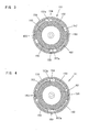
- FIG. 3 shows the state in which the outer rotor 123 is rotationally driven counterclockwise.
- the lock pins 159 are disposed between the outer surface of the power receiving member 157 and the inner surface of the fixed outer ring 158 in the spaces defined between the adjacent power transmitting parts 153.
- a planar region 157a is tangentially formed on the outer surface of the power receiving member 157 in the spaces in which the lock pins are disposed. Therefore, as shown in FIG. 3 , when the outer rotor 123 is rotationally driven, each of the lock pins 159 is about to be wedged into a wedge-shaped space between the outer surface of the power receiving member 157 and the inner surface of the fixed outer ring 158 by the difference of relative rotation between the power receiving member 157 and the fixed outer ring 158.
- the lock pin 159 is pushed by a front end surface of the power transmitting part 153 in the rotation direction and held on the planar region 157a. Therefore, the lock pin 159 is not wedged in and the torque of the outer rotor 123 is transmitted to the first internal gear 133 via the power receiving member 157.
- the power receiving member 157 When torque is inputted from the output side to the input side, or more specifically, for example, when load is applied to the first internal gear 133 (the spindle 115) side and the power receiving member 157 is about to rotate with respect the power transmitting part 153 in the state shown in FIG. 4 , the power receiving member 157 is locked in contact with the inner surface of the fixed outer ring 158 via the lock pins 159. Specifically, the lock pins 159 are wedged into the wedge-shaped spaces between the outer surface of the power receiving member 157 and the inner surface of the fixed outer ring 158, so that the power receiving member 157 is locked to the fixed outer ring 15 8.
- the bi-directional one-way clutch 151 is provided as a machine element which can transmit torque of the outer rotor 123 on the input (driving) side to the first internal gear 133 (the spindle 115) on the output (driven) side both in the clockwise and counterclockwise directions. Moreover, when torque is about to be inputted reversely from the output side to the input side by load applied to the output side, the bi-directional one-way clutch 151 locks the first internal gear 133 and interrupts transmission of torque from the output side to the input side both in the clockwise and counterclockwise directions.
- the spindle 115 when the first internal gear 133 is locked and the inner rotor 121 of the driving motor 111 is electrically driven, the spindle 115 is caused to rotate at a certain reduction ratio predetermined in the planetary gear mechanism 113.
- the first internal gear 133 serving as a reaction force receiving member rotates in the same direction as the first sun gear 131.
- the number of revolutions of the first planetary gears 135 around the first sun gear 131 increases by the number of rotations of the first internal gear 133, so that the rotation speed of the spindle 115 increases.
- the outer rotor 123 can be switched between the stopped state and the driven state in which it is driven in the same direction as the inner rotor 121 or in the opposite direction, while the inner rotor 121 is constantly and continuously driven.
- the revolution speed of the first planetary gears 135 (the rotation speed of the first carrier 137) can be changed so that the speed reduction ratio of the planetary gear mechanism 113 can be changed.
- the output torque and the rotation speed to be outputted to the spindle 115 can be changed by changing the speed reduction ratio of the planetary gear mechanism 113.
- the speed reduction ratio is changed according to load on the spindle 115 such as the driving current, torque, rotation speed and temperature of the driving motor 111.
- the speed reduction ratios set by switching the outer rotor 123 to the stopped state and the driven state while the inner rotor 121 is constantly driven are features that correspond to the "first and second speed reduction ratios", respectively, according to this embodiment.
- a fastener such as a screw and a bolt (hereinafter referred to as a screw or the like) by using the screwdriver 101
- the screw or the like is pressed against a workpiece via the screw bit 119, and in this state, a trigger 109a on the handgrip 109 is depressed to drive the driving motor 111.
- the spindle 115 is rotationally driven via the planetary gear mechanism 113, and the screw bit 119 rotates together with the spindle 115 and is allowed to perform the operation of tightening a screw or the like.
- the first sun gear 131 is constantly driven by the inner rotor 121 of the driving motor 111, and the first internal gear 133 can be driven and stopped by the outer rotor 123.
- the outer rotor 123 is intermittently driven, or repeatedly alternates between driving and stopping while the screw bit 119 is driven by constantly driving the inner rotor 121.
- the screw bit 119 which is being driven at an output torque outputted by the inner rotor 121 intermittently gains the output torque outputted by the outer rotor 123.
- torque for driving the screw bit 119 can be intermittently changed.
- intermittent torque change is also referred to as a torque ripple.
- the screwdriver 101 can be provided which can perform a screw tightening operation at a higher tightening torque than a usual tightening torque and is easy for a user to hold.
- torque ripple is caused by intermittent driving of the outer rotor 123 all the way through the screw tightening operation of the screw bit 119 which is constantly driven by the inner rotor 121, or such that it is caused somewhere in the screw tightening operation.
- torque ripple may be caused by intermittently driving the outer rotor 123 when load (tightening torque) increases upon seating of the screw on the workpiece during screw tightening operation of the screw bit 119 driven by the inner rotor 121.
- the impact type screwdriver 101 equivalent to one having a mechanical rotary impact mechanism which intermittently applies impact force to the screw bit 119 in the direction of rotation can be obtained without such a rotary impact mechanism.
- the outer rotor 123 is intermittently driven somewhere during driving of the screw bit 119 by the inner rotor 121, for example, at least one of the driving current, torque, rotation speed and temperature of the constantly driven inner rotor 121 may be detected by a detector, and a motor control device (controller) which is not shown may be used to control such that the outer rotor 123 starts intermittent driving when the value detected by the detector reaches a predetermined value.
- the first internal gear 133 receives a reaction force when the screw bit 119 is rotationally driven by the inner rotor 121. Therefore, the outer rotor 123 needs to generate higher torque than the inner rotor 121 in order to cause torque ripple by driving of the outer rotor 123. During the time when torque ripple is not caused, or when the screw bit 119 is driven only by driving of the inner rotor 121, the first internal gear 133 needs to be held in the locked state. If the first internal gear 133 is held in the locked state only by torque of the outer rotor 123, the outer rotor 123 is used in the locked state, which may cause motor burnout.
- the bi-directional one-way clutch 151 is provided between the outer rotor 123 and the first internal gear 133 of the planetary gear mechanism 113 and interrupts reverse input of power from the first internal gear 133 on the driven side to the outer rotor 123 on the input side so that the first internal gear 133 can be held in the locked state.
- the outer rotor 123 can be protected from burnout.
- the rotation axis of the dual rotor motor which forms the driving motor 111 is arranged coaxially with the spindle 115 which drives the screw bit 119. Therefore, for example, compared with a construction in which two motors are arranged in parallel, the machine body is not bulged outward so that the compact screwdriver 101 can be provided.
- a cooling fan 161 for cooling the motor is provided on the inner rotor 121 which is constantly driven.
- the cooling fan 161 is provided on an axial end (rear end) of the inner rotor 121 facing away from the first sun gear 131.
- the cooling fan 161 serves to cool the driving motor 111 by taking outside air into the space of the motor housing 105 through an inlet (not shown) formed in the rear end of the motor housing 105, leading it forward in the longitudinal direction and then discharging it to the outside through an outlet (not shown) formed in the front of the housing.
- FIGS. 5 to 8 A second embodiment of the present invention is now described with reference to FIGS. 5 to 8 .
- the first internal gear 133 is constantly driven by the outer rotor 123, and the first sun gear 131 can be driven and stopped by the inner rotor 121.
- the outer rotor 123 is directly connected to the first internal gear 133, and the bi-directional one-way clutch 151 is disposed between the inner rotor shaft 121a of the inner rotor 121 and the first sun gear 131.
- this embodiment has the same construction as the above-described first embodiment. Therefore, components in this embodiment which are substantially identical to those in the first embodiment are given like numerals as in the first embodiment.
- the bi-directional one-way clutch 151 has basically the same construction and function as that in the first embodiment. Due to arrangement of the bi-directional one-way clutch 151 between the inner rotor shaft 121a and the first sun gear 131, however, the fixed outer ring 158 which forms the outer shell of the bi-directional one-way clutch 151 is connected to the front surface of the stator 125 of the driving motor 111 and has a generally cup-like shape having a circular central opening through which the first sun gear 131 is loosely inserted. Further, four power transmitting parts 153 are disposed at predetermined intervals in the circumferential direction and integrally formed with a disc-like power transmitting member 152.
- the power transmitting member 152 is connected to the inner rotor shaft 121a and rotates together with the inner rotor shaft 121a.
- the power receiving member 157 having the power receiving parts 155 is connected to the first sun gear 131 and rotates together with the first sun gear 131.
- the bi-directional one-way clutch 151 has the same construction as that in the first embodiment.
- the bi-directional one-way clutch 151 can transmit torque of the inner rotor 121 to the first sun gear 131 (the spindle 115) on the output (driven) side both in the clockwise and counterclockwise directions. Moreover, when torque is about to be inputted reversely from the output side to the input side by load applied to the output side, the bi-directional one-way clutch 151 locks the first sun gear 131 and interrupts transmission of torque from the output side to the input side both in the clockwise and counterclockwise directions.
- the first internal gear 133 is constantly driven by the outer rotor 123 of the driving motor 111, and the first sun gear 131 can be driven and stopped by the inner rotor 121. Therefore, while the spindle 115 (the screw bit 119) is driven by driving the outer rotor 123, the inner rotor 123 is intermittently driven, or repeatedly alternates between driving and stopping. In this manner, the screw bit 119 which is being driven at an output torque outputted by the outer rotor 123 intermittently gains the output torque outputted by the inner rotor 121. Thus, according to this embodiment, torque for driving the screw bit 119 can be intermittently changed.
- the first sun gear 131 receives a reaction force when the screw bit 119 is rotationally driven by the outer rotor 121. Therefore, the inner rotor 121 needs to generate higher torque than the outer rotor 123 in order to cause torque ripple by intermittent driving of the inner rotor 123. During the time when torque ripple is not caused, the first sun gear 131 needs to be held in the locked state by stopping driving the inner rotor 121. If the first sun gear 131 is held in the locked state only by torque of the inner rotor 121, motor burnout may be caused.
- the bi-directional one-way clutch 151 provided between the inner rotor 121 and the first sun gear 131 can interrupt reverse input of power from the driven-side first sun gear 131 to the input-side inner rotor 121 and hold the first internal gear 133 in the locked state.
- the outer rotor 123 can be protected from burnout.
- a cooling fan 163 for cooling the motor is provided on the outer rotor 123 which is constantly driven.
- the cooling fan 163 is provided on the inner circumferential surface of an axial end (rear end) of the outer rotor 123 on the opposite side from the first internal gear 133.
- the cooling fan 163 serves to cool the driving motor 111 by taking outside air into the space of the motor housing 105 through an inlet formed in the rear end of the motor housing 105 and leading it forward in the longitudinal direction.
- the air taken into the motor housing space cools the driving motor 111 by flowing into the motor through gaps between the stator 125 and the outer rotor 123 and between the stator 125 and the inner rotor 121.
- the air flows out to the outside of the motor through a radially extending communication hole 123a formed through a front end region of the outer rotor 123.
- the air then further passes between the motor housing 105 and the gear housing 107 and is discharged to the outside through an outlet.
- FIGS. 1 to 4 A third embodiment of the present invention is now described with reference to FIGS. 1 to 4 .
- the screw bit 119 is constantly driven by using one of the rotors, and in this state, the speed reduction ratio of the planetary gear mechanism 113 can be changed according to the load (tightening torque) on the screw bit 119 (the spindle 115) by using the other rotor, so that the rotation speed (screw tightening speed) of the screw bit 119 can be automatically changed.
- the entire construction of the screwdriver 101 is the same as the above-described first embodiment and therefore it is not described.
- it is constructed such that the inner rotor 121 and the outer rotor 123 are simultaneously driven when the trigger 109a is depressed.
- the first internal gear 133 receives a small reaction to the rotation driving force.
- the first sun gear 131 is rotationally driven by the inner rotor 121, and the first internal gear 133 is rotationally driven in the direction of rotation of the first sun gear 131. Therefore, the screw bit 119 is rotated together with the spindle 115 at high speed at the speed reduction ratio at which the first sun gear 131 and the first internal gear 133 rotate together.
- the first internal gear 133 receives an increased reaction to the rotation driving force.
- the driving force of the outer rotor 123 is low, the torque of the outer rotor 123 succumbs to this reaction force, so that the first internal gear 133 is about to be rotated in the reverse direction.
- the bi-directional one-way clutch 151 is actuated and locks the first internal gear 133 to the fixed outer ring 158. Therefore, the screw bit 119 is rotated together with the spindle 115 at low speed at the speed reduction ratio at which only the first sun gear 131 rotates.
- the low-speed rotation of the spindle 115 is detected, for example, by electric current values.
- a current detector is used to detect that the driving current of the outer rotor 123 has reached a predetermined value.
- the motor control device receives this detected signal and stops energization for driving the outer rotor 123, so that the outer rotor 123 can be protected from burnout.
- the speed reduction ratio at which the first sun gear 131 and the first internal gear 133 rotate together and the speed reduction ratio at which only the first sun gear 131 rotates are features that correspond to the "first and second speed reduction ratios", respectively, according to this invention.
- the spindle 115 can be rotated at high speed in low load conditions in which the tightening torque is low, while it can be rotated at low speed in high load conditions in which the tightening torque is increased.
- a screw tightening operation can be performed more rapidly with higher accuracy.
- it can be provided such that the output torque of the outer rotor 123 is lower than the output torque of the inner rotor 121, so that the outer rotor 123 can be reduced in size.
- FIGS. 9 and 10 A fourth embodiment of the present invention is now described with reference to FIGS. 9 and 10 .
- the first sun gear 131 ofthe planetary gear mechanism 113 is driven by the inner rotor 121 to rotationally drive the spindle 115 (the screw bit 119) via the planetary gear mechanism 113, while a cooling fan 165 is driven by the outer rotor 123.
- this embodiment has generally the same construction as the first embodiment except that the bi-directional one-way clutch 151 is not provided and the first and second internal gears 133, 141 are formed in one piece and fixed to the gear housing 107 side in the planetary gear mechanism 113. Therefore, components in this embodiment which are substantially identical to those in the first embodiment are given like numerals as in the first embodiment, and they are not described.
- a cylindrical fan housing part 124 is formed on one (front) end of the outer rotor 123 in the longitudinal direction and extends forward of the front ends of the stator 125 and the inner rotor 121 (toward the planetary gear mechanism 113).
- the cooling fan 165 for cooling the motor is housed and fixed within the fan housing part 124.
- the fan housing part 124 is a feature that corresponds to the "extending region”
- the cooling fan 165 is a feature that corresponds to the "actuating member other than the tool bit” and the "fan” according to this invention.
- the electric current value of the driving motor 111 is monitored.
- the cooling fan 165 is stopped, and when the amount of heat generation of the driving motor 111 is large, for example, during operation, the outer rotor 123 is driven to drive the cooling fan 165.
- the cooling fan 165 independently of driving of the spindle 115 by the inner rotor 121, the cooling fan 165 can be driven by the outer rotor 123. Therefore, regardless of the operational status of the spindle 115 (the screw bit 119), the cooling fan 165 can be constantly driven at the maximum speed. Therefore, the effect of cooling the driving motor 111 can be improved, so that the driving motor 111 can be protected from burnout. Further, the inner rotor 121 is exclusively used for driving the spindle 115 and not used for driving the cooling fan 165. Accordingly, the output of the inner rotor 121 is improved. Further, when the amount of heat generation of the driving motor 111 is small, the cooling fan 165 can be stopped, so that generation of noise can be lessened.
- the inner rotor 121, the stator 125 and the outer rotor 123 can be simultaneously cooled by the one cooling fan 165, and the relatively large cooling fan can be mounted without increasing the size of the machine body.
- the cooling effect can be easily obtained.
- a fifth embodiment of the present invention is now described with reference to FIG. 11 .
- This embodiment is a modification to the fourth embodiment and different from the fourth embodiment in that, in addition to the motor cooling fan 165 mounted to the outer rotor 123, a cooling fan 167 for cooling the motor is mounted to the inner rotor 121.
- this embodiment has the same construction as the above-described fourth embodiment.
- the cooling fan 167 to be driven by the inner rotor 121 is provided rearward of the rear end surface of the stator 125 on the rear end of the inner rotor 121.
- Each of the cooling fans 165, 167 is a feature that corresponds to the "actuating member other than the tool bit" and the "fan” according to this invention.
- the motor is cooled by the cooling fan 167 even during normal operation in which the spindle 115 is rotationally driven by driving the inner rotor 121.
- the operating time of the outer rotor 123 can be shortened.
- the electric current value of the driving motor 111 is monitored.
- the cooling fan 165 can be driven by the outer rotor 123 so that the cooling capacity can be improved. Therefore, this embodiment can be suitably applied to a tightening tool which is used under relatively high-load conditions.
- the cooling fan 165 which is driven by the outer rotor 123 is used only under high-load conditions, so that the amount of screw tightening operation per charge can be easily ensured.
- the relatively large cooling fan can be mounted without increasing the size of the machine body.
- the cooling effect can be easily obtained.
- the driving coil mechanism is described as having the inner rotor driving coil for driving the inner rotor 121 and an outer rotor driving coil for driving the outer rotor 123.
- it may have a construction in which two kinds of electric current are passed through a common driving coil such that the inner rotor 121 and the outer rotor 123 are individually driven, or specifically, such that one driving coil is used to drive the inner rotor 121 and the outer rotor 123.
- the stator 125 of the driving motor 111 in the first embodiment is formed by a stator for an outer rotor and a stator for an inner rotor.
- this embodiment has generally the same construction as the above-described first embodiment. Therefore, this embodiment is described with a focus on the driving motor 111 which is different from that of the first embodiment.
- FIG. 13 shows an essential part of the screwdriver 101.
- the driving motor 111 has an inner rotor 121 (first rotor), an outer rotor 123 (second rotor), a stator for the inner rotor (hereinafter referred to as an inner stator) 125A on which an inner-rotor driving coil 125a for driving the inner rotor 121 is wound, and a stator for the outer rotor (hereinafter referred to as an outer stator) 125B on which an outer-rotor driving coil 125b for driving the outer rotor 123 is wound.
- the driving motor 111 is configured as a dual rotor motor in which the inner rotor 121 and the outer rotor 123 are arranged coaxially inside of the inner stator 125A and outside of the outer stator 125B, respectively.
- the inner stator 125A and the outer stator 125B are features that correspond to the "first stator” and the “second stator”, respectively, according to this invention.
- the inner-rotor driving coil 125a and the outer-rotor driving coil 125b form the "driving coil mechanism".
- the inner stator 125A and the outer stator 125B are generally doughnut-shaped.
- the inner stator 125A includes an annular yoke 125A1, a plurality of teeth 125A2 and a plurality of slots.
- the teeth 125A2 extend radially inward from the inner circumferential surface of the yoke 125A1 and spaced apart from each other, and an inner-rotor driving coil (which is not shown in FIGS. 16 to 19 ) is wound around the teeth 125A2.
- the outer stator 125B has a ring-like stator body 125B1, a plurality ofteeth 125B2 and a plurality of slots.
- the teeth 125B2 extend radially outward from the outer circumferential surface of the stator body 125B1 and spaced apart from each other, and an outer-rotor driving coil (which is not shown in FIGS. 16 to 19 ) is wound around the teeth 125B2.
- the inner rotor 121 having four magnets 121b fixed on its outer circumferential surface and the inner stator 125A having six slots form a four-pole six-slot inner motor.
- the outer rotor 123 having eight magnets 123b fixed on the inner circumferential surface of the outer rotor 123 and the outer stator 125B having eight slots form an eight-pole six-slot outer motor.
- the inner motor and the outer motor are arranged at positions displaced from each other in the longitudinal direction within the motor housing 105, or more specifically, such that the outer motor is located forward of the inner motor.
- the yoke 125A1 of the inner stator 125A and the yoke 125B1 of the outer stator 125B have generally the same inner and outer diameters, and a rear surface of the yoke 125B1 of the outer stator 125B and a front surface of the yoke 125A1 of the inner stator 125A are aligned and connected together (see FIGS. 17 and 20 ).
- the yokes 125A1, 125B1 of the inner and outer stators 125A, 125B are configured to be aligned in contact with each other and connected together by a connecting member in the form of a plurality of pins 125c (see FIG.
- connection methods may be provided to connect the inner and outer stators 125A, 125B in place of the above-described method using the pins 125c.
- mechanical connection using a plurality of screws or the like, connection via a resin layer by resin molding, or connection using an adhesive can be used.
- the inner and outer stators 125A, 125B are arranged at positions displaced from each other in the longitudinal direction and connected together as described above, so that an annular space is created between the outer circumferential region of the yoke 125A1 of the inner stator 125A and the inner wall surface of the motor housing 105.
- this space is utilized to provide a supporting member 126 via which the motor housing 105 can support the outer circumferential region of the yoke 125A1 from outside.
- the supporting member 126 is provided, for example, as an annular member formed separately from the motor housing 105, or as an annular member integrally extending inward from the inner wall of the motor housing 105.
- the outer and inner peripheries of the supporting member 126 are fixed to the motor housing 105 and the yoke 125A1 of the inner stator 125A, respectively.
- the inner rotor 121 is disposed inside ofthe inner stator 125A.
- the inner rotor 121 is rotatably supported at the front via a bearing 127 with respect to a bearing housing 127A which is disposed inside ofthe outer stator 125B, and it is rotatably supported at the rear via a bearing 128 with respect to the motor housing 105.
- the outer rotor 123 is generally cylindrical and disposed outside ofthe outer stator 125B.
- the outer rotor 123 is rotatably supported on its outer periphery via front and rear bearings 128 with respect to the motor housing 105.
- the inner rotor 121 and the outer rotor 123 are independently and individually driven and stopped. Further, predetermined air gaps are provided between the inner rotor 121 and the inner stator 125A and between the outer rotor 123 and the outer stator 125B.
- the planetary gear mechanism 113 is disposed in front of the driving motor 111 having the above-described construction.
- the rotation output of the driving motor 111 is reduced in speed by the planetary gear mechanism 113 and transmitted to the spindle 115 and then to the screw bit 119 which is held by the spindle 115 via the bit holder 117.
- the planetary gear mechanism 113 is a feature that corresponds to the "speed reducing mechanism" according to the present invention.
- the planetary gear mechanism 113 and the overload clutch 147 disposed between the planetary gear mechanism 113 and the spindle 115 have the same construction and effect as the above-described first embodiment. Therefore, their description is omitted.
- the outer rotor 123 is connected to the first internal gear 133 of the planetary gear mechanism 113 via the bi-directional one-way clutch 151.
- the bi-directional one-way clutch 151 is a feature that corresponds to the "clutch" according to this invention. As shown in FIGS. 14 and 15 , the bi-directional one-way clutch 151 is provided as a machine element which can transmit torque of the outer rotor 123 on the input side (driving side) to the first internal gear 133 (the spindle 115) on the output side (driven side) both in the clockwise and counterclockwise directions.
- the bi-directional one-way clutch 151 when torque is about to be inputted reversely from the output side to the input side by load applied to the output side, the bi-directional one-way clutch 151 is locked to interrupt transmission of torque from the output side to the input side both in the clockwise and counterclockwise directions.
- the bi-directional one-way clutch 151 has the same construction and effect as the above-described first embodiment. Therefore, their description is omitted.
- the spindle 115 when the first internal gear 133 is locked and the inner rotor 121 of the driving motor 111 is electrically driven, the spindle 115 is caused to rotate at a certain reduction ratio predetermined in the planetary gear mechanism 113.
- the first internal gear 133 serving as a reaction force receiving member rotates in the same direction as the first sun gear 131.
- the number of revolutions of the first planetary gears 135 around the first sun gear 131 increases by the number of rotations of the first internal gear 133, so that the rotation speed of the spindle 115 increases.
- the outer rotor 123 can be switched between the stopped state and the driven state in which it is driven in the same direction as the inner rotor 121 or in the opposite direction, while the inner rotor 121 is constantly and continuously driven.
- the revolution speed of the first planetary gears 135 (the rotation speed of the first carrier 137) can be changed so that the speed reduction ratio of the planetary gear mechanism 113 can be changed.
- the output torque and the rotation speed to be outputted to the spindle 115 can be changed by changing the speed reduction ratio of the planetary gear mechanism 113.
- the speed reduction ratio is changed according to load on the spindle 115 such as the driving current, torque, rotation speed and temperature of the driving motor 111.
- the speed reduction ratios set by switching the outer rotor 123 to the stopped state and the driven state while the inner rotor 121 is constantly driven are features that correspond to the "first and second speed reduction ratios", respectively, according to this embodiment.
- the inner rotor 121 and the inner stator 125A form the inner motor and the outer rotor 123 and the outer stator 125B form the outer motor.
- the inner motor and the outer motor are arranged at positions displaced from each other in the longitudinal direction within the housing 105. Therefore, a space is created between the outer circumferential region of the inner motor (or the inner stator 125A) and the inner wall surface of the motor housing 105. This space is utilized to provide a supporting member 126 via which the motor housing 105 can support (hold) the outer circumferential region of the inner stator 125A of the inner motor. Therefore, for example, compared with a structure of holding an end surface (side) of the stator in the longitudinal direction, the stator can be firmly supported with a simpler structure.
- the yokes 125A1, 125B1 of the inner and outer stators 125A, 125B are aligned in contact with each other in the longitudinal direction and connected together by the pins 125c in the aligned region.
- the inner and outer stators 125A, 125B can be connected together in a rational manner.
- the driving motor 111 of this modification has an inner rotor 121 (first rotor), an outer rotor 123 (second rotor), a stator for the inner rotor (hereinafter referred to as an inner stator) 125A on which an inner-rotor driving coil 125a for driving the inner rotor 121 is wound, and a stator for the outer rotor (hereinafter referred to as an outer stator) 125B on which an outer-rotor driving coil 125b for driving the outer rotor 123 is wound.
- the inner rotor 121 is disposed inside of the inner stator 125A, and the outer rotor 123 is disposed in front of the outer stator 125B to face each other.
- the driving motor 111 is configured as a dual rotor motor in which the inner rotor 121 and the outer rotor 123 are arranged coaxially.
- the inner motor having the inner rotor 121 and the inner stator 125A is configured as a radial gap motor in which the inner rotor 121 and the inner stator 125A are opposed to each other in the radial direction
- the outer motor having the outer rotor 123 and the outer stator 125B is configured as an axial gap motor in which the outer rotor 123 and the outer stator 125B are opposed to each other in the longitudinal direction.
- the inner motor having the inner rotor 121 and the inner stator 125A and the outer motor are arranged at positions displaced from each other in the longitudinal direction, or more specifically, such that the outer motor is located forward of the inner motor.
- An outer circumferential surface of the front end of the yoke 125A1 of the inner stator 125A in the inner motor and an inner circumferential surface of the yoke 125B1 of the outer stator 125B in the outer motor are configured to be aligned in contact with each other and connected together in the aligned region, for example, via a resin layer by resin molding, or by using an adhesive.
- the outer motor is configured as an axial gap motor in which the outer rotor 123 and the outer stator 125B are opposed to each other in the longitudinal direction, so that a space is created between the outer circumferential surface of the outer stator 125B and the inner wall surface of the motor housing 105.
- This space is utilized, for example, to provide an annular supporting part 105A which is integrally formed with the inner wall of the motor housing 105 (or an annular member which is formed separately from the motor housing 105) and supports the outer stator 125B from outside.
- the structure of supporting the outer circumferential region of the outer stator 125B from outside by the supporting part 105A of the motor housing 105 is provided in addition to the structure of supporting the outer circumferential region of the inner stator 125A of the inner motor from outside by the motor housing 105 via the supporting member 126.
- the stator can be more firmly supported.
- the outer stator 125B of the outer motor is disposed outside of the inner stator 125A. Therefore, it can be constructed as shown in the drawing such that part 127a of the bearing housing 127A extends to the yoke 125A1 of the inner stator 125A and supports the front surface of the yoke 125A1. With this construction, the stator can be further more firmly supported.
- FIGS. 24 to 27 A seventh embodiment of the present invention is now described with reference to FIGS. 24 to 27 .
- the first internal gear 133 is constantly driven by the outer rotor 123, and the first sun gear 131 can be driven and stopped by the inner rotor 121.
- the outer rotor 123 is directly connected to the first internal gear 133, and the bi-directional one-way clutch 151 is disposed between the inner rotor shaft 121a of the inner rotor 121 and the first sun gear 131.
- this embodiment has the same construction as the above-described sixth embodiment, including the structure of supporting the outer circumferential region of the inner stator 125A by the supporting member 126. Therefore, components in this embodiment which are substantially identical to those in the sixth embodiment are given like numerals as in the sixth embodiment.
- the bi-directional one-way clutch 151 has basically the same construction and function as that in the sixth embodiment (and thus the first embodiment). Due to arrangement of the bi-directional one-way clutch 151 between the inner rotor shaft 121 a and the first sun gear 131, however, the fixed outer ring 158 which forms the outer shell of the bi-directional one-way clutch 151 is connected to the inside of the outer stator 125B in front of the inner stator 125A of the driving motor 111 and has a generally cup-like shape having a circular central opening through which the first sun gear 131 is loosely inserted.
- the power transmitting member 152 is connected to the inner rotor shaft 121a and rotates together with the inner rotor shaft 121a.
- the power receiving member 157 having the power receiving parts 155 is connected to the first sun gear 131 and rotates together with the first sun gear 131.
- the bi-directional one-way clutch 151 has the same construction as that in the sixth embodiment (and thus the first embodiment).
- the bi-directional one-way clutch 151 can transmit torque of the inner rotor 121 to the first sun gear 131 (the spindle 115) on the output (driven) side both in the clockwise and counterclockwise directions. Moreover, when torque is about to be inputted reversely from the output side to the input side by load applied to the output side, the bi-directional one-way clutch 151 locks the first sun gear 131 and interrupts transmission of torque from the output side to the input side both in the clockwise and counterclockwise directions.
- the first internal gear 133 is constantly driven by the outer rotor 123 of the driving motor 111, and the first sun gear 131 can be driven and stopped by the inner rotor 121. Therefore, while the spindle 115 (the screw bit 119) is driven by driving the outer rotor 123, the inner rotor 123 is intermittently driven, or repeatedly alternates between driving and stopping. In this manner, the screw bit 119 which is being driven at an output torque outputted by the outer rotor 123 intermittently gains the output torque outputted by the inner rotor 121. Thus, according to this embodiment, torque for driving the screw bit 119 can be intermittently changed.
- the first sun gear 131 receives a reaction force when the screw bit 119 is rotationally driven by the outer rotor 121. Therefore, the inner rotor 121 needs to generate higher torque than the outer rotor 123 in order to cause torque ripple by intermittent driving of the inner rotor 123. During the time when torque ripple is not caused, the first sun gear 131 needs to be held in the locked state by stopping driving of the inner rotor 121. If the first sun gear 131 is held in the locked state only by torque of the inner rotor 121, motor burnout may be caused.
- the bi-directional one-way clutch 151 provided between the inner rotor 121 and the first sun gear 131 can interrupt reverse input of power from the first sun gear 131 on the driven side to the inner rotor 121 on the input side and hold the first internal gear 133 in the locked state.
- the outer rotor 123 can be protected from burnout.
- a cooling fan 163 for cooling the motor is provided on the outer rotor 123 which is constantly driven.
- the cooling fan 163 is provided on the inner circumferential surface of an axial end (rear end) of the outer rotor 123 on the opposite side from the first internal gear 133.
- the cooling fan 163 serves to cool the driving motor 111 by taking outside air into the space of the motor housing 105 through an inlet formed in the rear end of the motor housing 105 and leading it forward in the longitudinal direction.
- the air taken into the motor housing space cools the driving motor 111 by flowing into the motor through gaps between the outer stator 125B and the outer rotor 123 and between the inner stator 125A and the inner rotor 121.
- the air flows out to the outside of the motor through a radially extending communication hole 123 a (see FIG. 25 ) formed through a front end region ofthe outer rotor 123.
- the air then further passes between the motor housing 105 and the gear housing 107 and is discharged to the outside through an outlet.
- the supporting member 126 for supporting the inner stator 125A may be provided with air holes which extend through it in the longitudinal direction such that the cooling air can be led to the gap between the outer stator 125B and the outer rotor 123.
- FIGS. 28 and 29 An eighth embodiment of the present invention is now described with reference to FIGS. 28 and 29 .
- the first sun gear 131 of the planetary gear mechanism 113 is driven by the inner rotor 121 to rotationally drive the spindle 115 (the screw bit 119) via the planetary gear mechanism 113, while a cooling fan 165 is driven by the outer rotor 123.
- this embodiment has generally the same construction as the sixth embodiment, except that the bi-directional one-way clutch 151 is not provided and the first and second internal gears 133, 141 are formed in one piece and fixed to the gear housing 107 side in the planetary gear mechanism 113 and further that the outer circumferential region of the inner stator 125A is supported by the supporting member 126. Therefore, components in this embodiment which are substantially identical to those in the sixth embodiment are given like numerals as in the sixth embodiment, and they are not described.
- a cylindrical fan housing part 124 is formed on one (front) end of the outer rotor 123 in the longitudinal direction and extends forward of the front ends of the outer stator 125B and the inner rotor 121 (toward the planetary gear mechanism 113).
- the cooling fan 165 for cooling the motor is housed and fixed within the fan housing part 124.
- the fan housing part 124 is a feature that corresponds to the "extending region”
- the cooling fan 165 is a feature that corresponds to the "actuating member other than the tool bit” and the "fan” according to this invention.
- the electric current value of the driving motor 111 is monitored.
- the cooling fan 165 is stopped, and when the amount of heat generation of the driving motor 111 is large, for example, during operation, the outer rotor 123 is driven to drive the cooling fan 165.
- the cooling fan 165 independently of driving of the spindle 115 by the inner rotor 121, the cooling fan 165 can be driven by the outer rotor 123. Therefore, regardless of the operational status of the spindle 115 (the screw bit 119), the cooling fan 165 can be constantly driven at the maximum speed. Therefore, the effect of cooling the driving motor 111 can be improved, so that the driving motor 111 can be protected from burnout. Further, the inner rotor 121 is exclusively used for driving the spindle 115 and not used for driving the cooling fan 165. Accordingly, the output of the inner rotor 121 is improved. Further, when the amount of heat generation of the driving motor 111 is small, the cooling fan 165 can be stopped, so that generation of noise can be lessened.
- the inner rotor 121, the inner and outer stators 125A, 125B and the outer rotor 123 can be simultaneously cooled by the one cooling fan 165, and the relatively large cooling fan can be mounted without increasing the size of the machine body.
- the cooling effect can be easily obtained.
- a ninth embodiment of the present invention is now described with reference to FIG. 30 .
- This embodiment is a modification to the eighth embodiment and different from the eighth embodiment in that, in addition to the motor cooling fan 165 mounted to the outer rotor 123, a cooling fan 167 for cooling the motor is mounted to the inner rotor 121.
- this embodiment has the same construction as the above-described eighth embodiment.
- the cooling fan 167 to be driven by the inner rotor 121 is provided rearward of the rear end surface of the inner stator 125A on the rear end of the inner rotor 121.
- Each of the cooling fans 165, 167 is a feature that corresponds to the "actuating member other than the tool bit" and the "fan” according to this invention.
- the motor is cooled by the cooling fan 167 even during normal operation in which the spindle 115 is rotationally driven by driving the inner rotor 121.
- the operating time of the outer rotor 123 can be shortened.
- the electric current value of the driving motor 111 is monitored.
- the cooling fan 165 can be driven by the outer rotor 123 so that the cooling capacity can be improved. Therefore, this embodiment can be suitably applied to a tightening tool which is used under relatively high-load conditions.
- the cooling fan 165 which is driven by the outer rotor 123 is used only under high-load conditions, so that the amount of screw tightening operation per charge can be easily ensured.
- the relatively large cooling fan can be mounted without increasing the size of the machine body.
- the cooling effect can be easily obtained.
- a dust collecting fan which is not shown, is driven by one or both of the inner rotor 121 and the outer rotor 123.
- a dust collecting device is provided to collect dust which is generated during drilling operation on a workpiece with a drill bit coupled to the spindle 115.
- the dust collecting fan is provided as a suction force generating means for sucking dust generated by the drilling operation. Therefore, by provision of the construction in which the suction force generating means in the form of the dust collecting fan is driven by one or both of the inner rotor 121 and the outer rotor 123, the power tool with a dust collecting device can be rationally provided.
- the screwdriver is explained as a representative example of the power tool, but the present invention may be applied not only to a fastening tool for fastening screws or the like, but to a drill for drilling operation, a hammer and a hammer drill for chipping operation and drilling operation, and a circular saw and an electric cutter for cutting operation in wood or metal working.
Abstract
Description
- The present invention relates to a power tool that performs a predetermined operation on a workpiece with a tool bit driven by a motor.
- Japanese laid-open patent publication No.
2007-295773 - In the known screw tightening machine, however, by provision of the construction in which rotation and impact are given to the tool bit, it is likely to have a complicated device configuration by any means.
- Accordingly, it is an object of the present invention to provide a power tool that can realize various kinds of required operations in a simple device configuration.
- In order to solve the above-described problem, according to a preferred embodiment of the present invention, a power tool is provided which performs a predetermined operation on a workpiece with a tool bit driven by a motor. The "predetermined operation" in the present invention represents an operation of tightening screws, bolts or the like by rotationally driving the tool bit in the form of a screw bit or a socket. It however widely includes not only the tightening operation, but a chipping or drilling operation by linearly driving a hammer bit or by rotationally driving it around its axis, and a cutting operation by rotationally driving a saw blade.
- In the preferred embodiment of the power tool of the present invention, it is characterized in that the motor includes an inner rotor, an outer rotor and a stator having a driving coil mechanism and is configured as a dual rotor motor in which the inner rotor is arranged coaxially inside of the outer rotor.
- The inner rotor and the outer rotor of the dual rotor motor can be driven and stopped independently from each other. Therefore, it may be constructed to drive the tool bit by using both the inner rotor and the outer rotor, or alternatively, to drive the tool bit by using one of the inner rotor and the outer rotor and drive an actuating member other than the tool bit by using the other rotor.
- If it is constructed to drive the tool bit by using both the inner rotor and the outer rotor, for example, in the case of the power tool in the form of a screw tightening machine, it can be constructed to rotationally drive the tool bit in the form of a screw bit by using one of the rotors while giving impact to the screw bit in the circumferential direction by using the other rotor. Further, if it is constructed to drive the tool bit by using one of the inner rotor and the outer rotor and drive an actuating member other than the tool bit by using the other rotor, it can be constructed to drive the actuating member other than the tool bit, for example, in the form of a motor cooling fan. Thus, according to this invention, various kinds of required operations can be realized in a simple device configuration. Further, the dual rotor motor can be arranged coaxially with an output shaft which drives the tool bit. Therefore, for example, compared with a construction in which two motors are arranged in parallel, the machine body is not bulged outward so that the compact power tool can be provided.
- According to a further embodiment of the power tool of the present invention, the stator is formed by a single member. In this case, the "driving coil mechanism" may be constructed to include an inner rotor driving coil for driving the inner rotor and an outer rotor driving coil for driving the outer rotor, or it may be constructed to include one driving coil for driving both the inner rotor and the outer rotor.
- According to a further embodiment of the power tool of the present invention, the stator includes a plurality of members, or a first stator having an inner rotor driving coil for driving the inner rotor and a second stator having an outer rotor driving coil for driving the outer rotor.
- According to a further embodiment of the power tool of the present invention, in the construction in which the stator includes the first stator and the second stator, the power tool has a housing for housing the dual rotor motor, and the inner motor includes the inner rotor and the first stator and the outer motor includes the outer rotor and the second stator. Further, the inner motor and the outer motor are arranged in the housing at positions displaced from each other in the longitudinal direction, and a space is formed between an outer circumferential region of the inner motor and the housing. The "longitudinal direction" in this invention refers to the axial direction of the rotation axis of the inner rotor and the outer rotor.
According to this embodiment, the outer circumferential region of the inner motor can be supported (fixed) from outside by the housing. Therefore, compared with a structure of supporting an end surface (side) of the inner motor in the longitudinal direction, it can be firmly supported with a simpler structure. Specifically, in order to support the outer circumferential region of the inner motor, the outer circumferential region of the first stator is fixed to the housing directly or via a supporting member such as an annular member. - According to a further embodiment of the power tool of the present invention, the first and second stators are partly aligned in contact with each other in a radial direction transverse to the longitudinal direction and connected together in the aligned region.
According to this embodiment, the first and second stators can be connected together in a rational manner. For example, mechanical connection using pins, screws or the like, connection via a resin layer by resin molding, or connection using an adhesive can be used. - According to a further embodiment of the power tool of the present invention, the outer motor is configured as an axial gap motor in which the outer rotor and the second stator are opposed to each other in the longitudinal direction. In such a case, preferably, the first and second stators are partly aligned in the longitudinal direction and connected together in the aligned region. Further, preferably, the outer circumferential region of the second stator of the outer motor is fixedly supported by the housing directly or via a supporting member.
According to this embodiment, the dual rotor motor using a normal radial gap motor and an axial gap motor can be provided. - According to a further embodiment of the power tool of the present invention, the power tool has a speed reducing mechanism. Further, the dual rotor motor drives the tool bit via the speed reducing mechanism, and the speed reducing mechanism has at least first and second speed reduction ratios and switches at least one of the inner and outer rotors between a driven state and a stopped state to thereby switch between the first and second speed reduction ratios. In this case, preferably, the switching between the speed reduction ratios is made according to any one of an electric current value, torque, rotation speed and temperature of the dual rotor motor.
- According to a further embodiment of the power tool of the present invention, the output torque to be outputted to the tool bit is changed by the switching between the first and second speed reduction ratios.
According to this embodiment, the output torque of the tool bit can be changed by switching between the first and second speed reduction ratios. Therefore, the dual rotor motor can be used to drive the tool bit at high torque or low torque according to the load on the tool bit, during operation by the tool bit. - According to a further embodiment of the power tool of the present invention, the rotation speed of the tool bit is changed by the switching between the first and second speed reduction ratios.
According to this embodiment, the rotation speed of the tool bit can be changed between high speed and low speed by switching between the first and second speed reduction ratios. Therefore, by using the dual rotor motor, during operation by the tool bit, the tool bit can be driven at high speed in low load conditions, while it can be driven at low speed in high load conditions. - According to a further embodiment of the power tool of the present invention, the output torque of the tool bit is intermittently changed by continuously driving one of the inner rotor and the outer rotor and intermittently driving the other rotor.
According to this embodiment, the output torque of the tool bit can be intermittently changed. Therefore, for example, in the case of the power tool in the form of a screw tightening machine, by provision for intermittently changing the output torque of the tool bit after a screw is seated on the workpiece, the screw tightening machine of an impact type can be realized without need of using a mechanical mechanism such as a rotational impact mechanism for intermittently applying impact to the tool bit in the form of a screw bit in the direction of rotation. - According to a further embodiment of the power tool of the present invention, the speed reducing mechanism is formed by a planetary gear mechanism. Further, the planetary gear mechanism includes a sun gear and an internal gear which are coaxially arranged and a planetary gear which engages with both the sun gear and the internal gear and revolves around the sun gear. The internal gear is connected to the outer rotor and the sun gear is connected to the inner rotor. A difference of relative rotation between the sun gear and the internal gear is controlled by control of rotational driving of the outer rotor and the inner rotor, so that the revolution speed of the planetary gear is changed to switch the speed reduction ratio.
According to this embodiment, the dual rotor motor and the planetary gear mechanism can be connected to each other in a rational arrangement. - According to a further embodiment of the power tool of the present invention, in the construction in which the speed reducing mechanism is formed by the planetary gear mechanism, the inner rotor is constantly driven.
According to this embodiment, when the sun gear of the planetary gear mechanism is constantly driven by the inner rotor, the planetary gear which engages with the sun gear revolves while rotating. In this case, when the outer rotor is stopped, the internal gear is held in the stopped state. When the outer rotor is rotationally driven in the same direction as the inner rotor or in the opposite direction, the internal gear is rotationally driven in the same direction as the sun gear or in the opposite direction, so that the revolution speed of the planetary gear is changed. Thus, according to this embodiment, the speed reduction ratio of the planetary gear mechanism can be changed by switching the outer rotor between the driven state and the stopped state. - According to a further embodiment of the power tool of the present invention, in the construction in which the speed reducing mechanism is formed by the planetary gear mechanism, the outer rotor is constantly driven.
According to this embodiment, when the internal gear of the planetary gear mechanism is constantly driven by the outer rotor, the planetary gear which engages with the internal gear revolves while rotating. In this case, when the inner rotor is stopped, the sun gear is held in the stopped state. When the inner rotor is rotationally driven in the same direction as the outer rotor or in the opposite direction, the sun gear is rotationally driven in the same direction as the internal gear or in the opposite direction, so that the revolution speed of the planetary gear is changed. Thus, according to this embodiment, the speed reduction ratio of the planetary gear mechanism can be changed by switching the inner rotor between the driven state and the stopped state. - According to a further embodiment of the power tool of the present invention, the power tool includes a one-way clutch which is disposed between the outer rotor and the internal gear or between the inner rotor and the sun gear and transmits torque from the outer rotor and internal gear side to the tool bit side, but not in the reverse direction. The one-way clutch locks the internal gear or the sun gear against rotation according to torque on the tool bit and independently of rotation of the outer rotor or the inner rotor.
According to this embodiment, when the outer rotor or the inner rotor is stopped, the internal gear or the sun gear can be locked against rotation by the clutch. Therefore, reverse input of power from the internal gear or the sun gear to the outer rotor or the inner rotor can be interrupted, so that the motor can be protected. - According to a further embodiment of the power tool of the present invention, a fan is provided as the actuating member other than the tool bit. One of the inner rotor and the outer rotor of the dual rotor motor drives the tool bit and the other rotor drives the fan.
According to this embodiment, the fan provided as the actuating member other than the tool bit can be driven on the same axis. - According to a further embodiment of the power tool of the present invention, the outer rotor has an extending region formed on one end of the outer rotor in the longitudinal direction and extending forward of front ends of the stator and the inner rotor in the longitudinal direction. Further, the fan is disposed inside of the extending region of the outer rotor. With such a construction, a rational arrangement can be realized. In this case, the fan can be constructed to be constantly or intermittently driven.
- According to a further embodiment of the power tool of the present invention, the fan is provided as a cooling fan for cooling the dual rotor motor. The cooling fan is constructed to be constantly driven, or to be intermittently driven according to at least one of the temperature, rotation speed, torque and electric current value of the dual rotor motor.
- According to a further embodiment of the power tool of the present invention, the fan is provided as a dust collecting fan for collecting dust generated during operation and driven upon request for dust collection. The time of "request for dust collection" here typically represents the time when, in the case of the power tool in the form of a drilling or cutting tool, the tool bit is rotationally driven to perform a drilling or cutting operation.
- According to the present invention, a power tool is provided which can realize various kinds of required operations in a simple device configuration. Other objects, features and advantages of the present invention will be readily understood after reading the following detailed description together with the accompanying drawings and the claims.
-
-
FIG. 1 is a sectional side view schematically showing an entire screwdriver according to a first embodiment of the present invention. -
FIG. 2 is an enlarged sectional view of an essential part of the screwdriver. -
FIG. 3 is a sectional view of a bi-directional one-way clutch, taken along line A-A inFIG. 1 , in a lock released state. -
FIG. 4 is also a sectional view of the bi-directional one-way clutch, taken along line A-A inFIG. 1 , in a locked state. -
FIG. 5 is a sectional side view schematically showing a screwdriver according to a second embodiment of the present invention. -
FIG. 6 is an enlarged sectional view of an essential part of the screwdriver. -
FIG. 7 is a sectional view of a bi-directional one-way clutch, taken along line B-B inFIG. 5 , in a lock released state. -
FIG. 8 is also a sectional view of the bi-directional one-way clutch, taken along line B-B inFIG. 5 , in a locked state. -
FIG. 9 is a sectional side view schematically showing a screwdriver according to a fourth embodiment of the present invention. -
FIG. 10 is a sectional view showing a cooling fan, taken along line C-C inFIG. 9 . -
FIG. 11 is a sectional side view schematically showing a screwdriver according to a fifth embodiment of the present invention. -
FIG. 12 is a sectional side view schematically showing a screwdriver according to a sixth embodiment of the present invention. -
FIG. 13 is an enlarged sectional view of an essential part of the screwdriver. -
FIG. 14 is a sectional view of a bi-directional one-way clutch, taken along line D-D inFIG. 12 , in a lock released state. -
FIG. 15 is also a sectional view of the bi-directional one-way clutch, taken along line D-D inFIG. 12 , in a locked state.. -
FIG. 16 is an external view of a stator of a dual rotor motor according to the sixth embodiment. -
FIG. 17 is a sectional view taken along line E-E inFIG. 16 . -
FIG. 18 is a perspective view as viewed from the left inFIG. 16 . -
FIG. 19 is a perspective view as viewed from the right inFIG. 16 . -
FIG. 20 is a sectional view schematically showing a supporting (holding) structure ofthe stator in the dual rotor motor according to the sixth embodiment. -
FIG. 21 is a view showing only the motor as viewed from the direction of arrow F inFIG. 20 . -
FIG. 22 is a view showing only the motor as viewed from the direction of arrow G inFIG. 20 . -
FIG. 23 is a sectional view schematically showing a modification to the structure of the dual rotor motor according to the sixth embodiment. -
FIG. 24 is a sectional side view schematically showing a screwdriver according to a seventh embodiment of the present invention. -
FIG. 25 is an enlarged sectional view of an essential part of the screwdriver. -
FIG. 26 is a sectional view of a bi-directional one-way clutch, taken along line H-H inFIG. 24 , in a lock released state. -
FIG. 27 is also a sectional view of the bi-directional one-way clutch, taken along line H-H inFIG. 24 , in a locked state.. -
FIG. 28 is a sectional side view schematically showing a screwdriver according to an eighth embodiment of the present invention. -
FIG. 29 is a sectional view of a cooling fan, taken along line I-I inFIG. 28 . -
FIG. 30 is a sectional side view schematically showing a screwdriver according to a ninth embodiment of the present invention. - Each of the additional features and method steps disclosed above and below may be utilized separately or in conjunction with other features and method steps to manufacture and use improved power tools and methods for using them and devices utilized therein. Representative examples of the present invention, which examples utilized many of these additional features and method steps in conjunction, is now described in detail with reference to the drawings. This detailed description is merely intended to teach a person skilled in the art further details for practicing preferred aspects of the present teachings and is not intended to limit the scope of the invention. Only the claims define the scope of the claimed invention. Therefore, combinations of features and steps disclosed within the following detailed description may not be necessary to practice the invention in the broadest sense, and are instead taught merely to particularly describe some representative examples of the invention, which detailed description will now be given with reference to the accompanying drawings.
- A first embodiment of the present invention is now described with reference to
FIGS. 1 to 4 . A battery-powered screwdriver is described as a representative embodiment of a hand-held power tool according to the present invention.FIG. 1 shows ascrewdriver 101 according to this embodiment. As shown inFIG. 1 , thescrewdriver 101 according to this embodiment mainly includes abody 103 which forms an outer shell ofthescrewdriver 101, ascrew bit 119 detachably coupled to a front end of aspindle 115 via abit holder 117 in a front end region (left end region as viewed inFIG. 1 ) of thebody 103, and a handgrip (handle) 109 connected integrally to thebody 103. Thebody 103 and thescrew bit 119 are features that correspond to the "tool body" and the "tool bit", respectively, according to the present invention. Further, in this embodiment, for the sake of convenience of explanation, the side of thescrew bit 119 is taken as the front and the opposite side as the rear. - The
body 103 mainly includes amotor housing 105 that houses a drivingmotor 111, and agear housing 107 that houses a speed reducing mechanism in the form of aplanetary gear mechanism 113 and an output shaft in the form of thespindle 115 in front (on the left as viewed inFIGS. 1 and2 ) of the drivingmotor 111. The drivingmotor 111 is a feature that corresponds to the "motor" and the "dual rotor motor" according to the present invention. Themotor housing 105 has right and left halves connected to each other and covers the entire region of thegear housing 107 other than its front end region for supporting thespindle 115. Thehandgrip 109 extends in a downward direction transverse to the longitudinal direction of the body 103 (the axial direction of the screw bit 119), and abattery pack 110 is removably attached to the extending end of thehandgrip 109. Thebattery pack 110 contains a battery by which the drivingmotor 111 is powered. -
FIG. 2 shows a construction of an essential part of the screwdriver. As shown in the drawing, the drivingmotor 111 includes an inner rotor 121 (first rotor), an outer rotor 123 (second rotor), and astator 125 formed of a doughnut-shaped single member. An inner rotor driving coil (not shown) for driving theinner rotor 121 and an outer rotor driving coil (not shown) for driving theouter rotor 123 are wound on thestator 125. The drivingmotor 111 is a dual rotor motor having theinner rotor 121 and theouter rotor 123 arranged coaxially inside and outside of thestator 125, respectively. The inner rotor driving coil for driving theinner rotor 121 and the outer rotor driving coil for driving theouter rotor 123 form the "driving coil mechanism" according to this invention. - The
stator 125 is generally doughnut-shaped and fixedly mounted at its rear end to the motor housing of thebody 103. Theinner rotor 121 inside of thestator 125 is rotatably supported at its front end with respect to thestator 125 via abearing 127 and also rotatably supported at its rear end with respect to themotor housing 105 via abearing 128. Theouter rotor 123 is generally cylindrically shaped and rotatably supported at its front and rear ends of its outer circumferential surface with respect to themotor housing 105 viabearings 129. Theinner rotor 121 and theouter rotor 123 are driven and stopped independently from each other. - The
planetary gear mechanism 113 is disposed in front of the drivingmotor 111. The rotation output of the drivingmotor 111 is reduced in speed by theplanetary gear mechanism 113 and transmitted to thespindle 115 and then to thescrew bit 119 which is held by thespindle 115 via thebit holder 117. Theplanetary gear mechanism 113 is a feature that corresponds to the "speed reducing mechanism" according to the present invention. - The
planetary gear mechanism 113 includes afirst sun gear 131, a first internal gear (ring gear) 133, a plurality of firstplanetary gears 135, afirst carrier 137, asecond sun gear 139, a secondinternal gear 141, a plurality of secondplanetary gears 143 and asecond carrier 145. Theplanetary gear mechanism 113 reduces the speed of the rotation output of aninner rotor shaft 121a and transmits the rotation output to thespindle 115. - The
first sun gear 131 is connected to theinner rotor shaft 121a of theinner rotor 121 and rotates together. The first internal gear (ring gear) 133 is a ring-like member and has an outer surface rotatably supported with respect to thegear housing 107 and an inner surface having teeth. The firstinternal gear 133 is rotationally driven by theouter rotor 123. The firstplanetary gears 135 are engaged with thefirst sun gear 131 and the firstinternal gear 133 and revolve around the rotation axis of thefirst sun gear 131. Thefirst carrier 137 rotatably supports the firstplanetary gears 135 and rotates around the same axis as thefirst sun gear 131. Thesecond sun gear 139 is integrally formed on one (front) end of an outer circumferential surface of thefirst carrier 137 in the axial direction. The secondinternal gear 141 is fixed to thegear housing 107 and held in the stopped state at all times. The secondplanetary gears 143 are engaged with thesecond sun gear 139 and the secondinternal gear 141 and revolve around the rotation axis of thesecond sun gear 139. Thesecond carrier 145 rotatably supports the secondplanetary gears 143 and is connected to thespindle 115 via anoverload clutch 147. - The
overload clutch 147 is a known machine element which is provided to interrupt transmission of torque from thesecond carrier 145 to thespindle 115 when an excessive load is applied to thespindle 115. Therefore, its detailed description is omitted. Further, theplanetary gear mechanism 113 of this embodiment is constructed to have two carriers, or thefirst carrier 137 for supporting the firstplanetary gears 135 and thesecond carrier 145 for supporting the secondplanetary gears 143, which are connected in series in the axial direction, but it is not necessary to have two carriers. - The
outer rotor 123 is connected to the firstinternal gear 133 of theplanetary gear mechanism 113 via a bi-directional one-way clutch 151. The bi-directional one-way clutch 151 is a feature that corresponds to the "clutch" according to the present invention. As shown inFIGS. 3 and 4 , the bi-directional one-way clutch 151 mainly includes a ring-like fixedouter ring 158 which forms an outer shell of the bi-directional one-way clutch 151 and is integrally formed with thegear housing 107, apower transmitting part 153 which is integrally formed with an input shaft in the form of theouter rotor 123, apower receiving member 157 which is connected to the firstinternal gear 133, and acolumnar lock pin 159 which is disposed between thepower transmitting part 153 and thepower receiving member 157. Thelock pin 159 locks the firstinternal gear 133 against rotation when torque is inputted from the firstinternal gear 133 on the output side to theouter rotor 123 on the input side. - The
power transmitting part 153 consists of a plurality of members having a circular arc section and extending a predetermined length from the front end region of theouter rotor 123 in the axial direction, at predetermined intervals in the circumferential direction (four at 90-degree intervals in this embodiment). Thepower transmitting parts 153 are disposed for relative rotation inside ofthe fixedouter ring 158. Thepower receiving member 157 has a disc-like shape having a circular hole through which thefirst sun gear 131 can be loosely inserted. Thepower receiving member 157 is disposed for relative rotation inside of thepower transmitting parts 153. Thepower receiving member 157 has twopower receiving parts 155 formed on its outer surface with a 180-degree phase difference and protruding radially outward. Thepower receiving parts 155 are disposed with a predetermined clearance in the circumferential direction in two of the spaces which are defined between adjacent ones of thepower transmitting parts 153 and have a 180-degree phase difference. The lock pins 159 are disposed in the other two of the spaces defined between adjacent ones of thepower transmitting parts 153 and having a 180-degree phase difference. - When the
outer rotor 123 is rotationally driven clockwise, one of thepower transmitting parts 153 disposed on the opposite sides of thepower receiving part 155 of thepower receiving member 157 gets into contact with thepower receiving part 155 in the circumferential direction and transmits torque to the firstinternal gear 133 in the clockwise direction. When theouter rotor 123 is rotationally driven counterclockwise, the otherpower transmitting part 153 disposed on the opposite side ofthepower receiving part 155 gets into contact with thepower receiving part 155 in the circumferential direction and transmits torque to the firstinternal gear 133 in the counterclockwise direction.FIG. 3 shows the state in which theouter rotor 123 is rotationally driven counterclockwise. - The lock pins 159 are disposed between the outer surface of the
power receiving member 157 and the inner surface of the fixedouter ring 158 in the spaces defined between the adjacentpower transmitting parts 153. Aplanar region 157a is tangentially formed on the outer surface of thepower receiving member 157 in the spaces in which the lock pins are disposed. Therefore, as shown inFIG. 3 , when theouter rotor 123 is rotationally driven, each of the lock pins 159 is about to be wedged into a wedge-shaped space between the outer surface of thepower receiving member 157 and the inner surface of the fixedouter ring 158 by the difference of relative rotation between thepower receiving member 157 and the fixedouter ring 158. At this time, however, thelock pin 159 is pushed by a front end surface of thepower transmitting part 153 in the rotation direction and held on theplanar region 157a. Therefore, thelock pin 159 is not wedged in and the torque of theouter rotor 123 is transmitted to the firstinternal gear 133 via thepower receiving member 157. - When torque is inputted from the output side to the input side, or more specifically, for example, when load is applied to the first internal gear 133 (the spindle 115) side and the
power receiving member 157 is about to rotate with respect thepower transmitting part 153 in the state shown inFIG. 4 , thepower receiving member 157 is locked in contact with the inner surface of the fixedouter ring 158 via the lock pins 159. Specifically, the lock pins 159 are wedged into the wedge-shaped spaces between the outer surface of thepower receiving member 157 and the inner surface of the fixedouter ring 158, so that thepower receiving member 157 is locked to the fixed outer ring 15 8. - As described above, the bi-directional one-
way clutch 151 is provided as a machine element which can transmit torque of theouter rotor 123 on the input (driving) side to the first internal gear 133 (the spindle 115) on the output (driven) side both in the clockwise and counterclockwise directions. Moreover, when torque is about to be inputted reversely from the output side to the input side by load applied to the output side, the bi-directional one-way clutch 151 locks the firstinternal gear 133 and interrupts transmission of torque from the output side to the input side both in the clockwise and counterclockwise directions. - In this embodiment, when the first
internal gear 133 is locked and theinner rotor 121 of the drivingmotor 111 is electrically driven, thespindle 115 is caused to rotate at a certain reduction ratio predetermined in theplanetary gear mechanism 113. In this state, when theouter rotor 123 is rotated in the same direction as theinner rotor 121, the firstinternal gear 133 serving as a reaction force receiving member rotates in the same direction as thefirst sun gear 131. As a result, the number of revolutions of the firstplanetary gears 135 around thefirst sun gear 131 increases by the number of rotations of the firstinternal gear 133, so that the rotation speed of thespindle 115 increases. On the other hand, when theouter rotor 123 is rotated in the opposite direction, the number of revolutions of the firstplanetary gears 135 decreases by the number of rotations of the firstinternal gear 133, so that the rotation speed of thespindle 115 decreases. - In this manner, according to this embodiment, the
outer rotor 123 can be switched between the stopped state and the driven state in which it is driven in the same direction as theinner rotor 121 or in the opposite direction, while theinner rotor 121 is constantly and continuously driven. By this switching, the revolution speed of the first planetary gears 135 (the rotation speed of the first carrier 137) can be changed so that the speed reduction ratio of theplanetary gear mechanism 113 can be changed. Specifically, the output torque and the rotation speed to be outputted to thespindle 115 can be changed by changing the speed reduction ratio of theplanetary gear mechanism 113. Further, the speed reduction ratio is changed according to load on thespindle 115 such as the driving current, torque, rotation speed and temperature of the drivingmotor 111. The speed reduction ratios set by switching theouter rotor 123 to the stopped state and the driven state while theinner rotor 121 is constantly driven are features that correspond to the "first and second speed reduction ratios", respectively, according to this embodiment. - In order to tighten a fastener such as a screw and a bolt (hereinafter referred to as a screw or the like) by using the
screwdriver 101, the screw or the like is pressed against a workpiece via thescrew bit 119, and in this state, atrigger 109a on thehandgrip 109 is depressed to drive the drivingmotor 111. As a result, thespindle 115 is rotationally driven via theplanetary gear mechanism 113, and thescrew bit 119 rotates together with thespindle 115 and is allowed to perform the operation of tightening a screw or the like. - In this case, in this embodiment, the
first sun gear 131 is constantly driven by theinner rotor 121 of the drivingmotor 111, and the firstinternal gear 133 can be driven and stopped by theouter rotor 123. - Specifically, the
outer rotor 123 is intermittently driven, or repeatedly alternates between driving and stopping while thescrew bit 119 is driven by constantly driving theinner rotor 121. In this manner, thescrew bit 119 which is being driven at an output torque outputted by theinner rotor 121 intermittently gains the output torque outputted by theouter rotor 123. Thus, torque for driving thescrew bit 119 can be intermittently changed. In the following description, intermittent torque change is also referred to as a torque ripple. - Thus, according to this embodiment, by intermittently driving the
outer rotor 123, the operation of temporarily increasing the output torque to be outputted to thescrew bit 119 and then immediately returning it to its initial state can be repeated. As a result, a smaller reaction force is required to hold thescrewdriver 101. Therefore, thescrewdriver 101 can be provided which can perform a screw tightening operation at a higher tightening torque than a usual tightening torque and is easy for a user to hold. - It may be constructed such that torque ripple is caused by intermittent driving of the
outer rotor 123 all the way through the screw tightening operation of thescrew bit 119 which is constantly driven by theinner rotor 121, or such that it is caused somewhere in the screw tightening operation. In order to cause torque ripple somewhere, suitably, for example, torque ripple may be caused by intermittently driving theouter rotor 123 when load (tightening torque) increases upon seating of the screw on the workpiece during screw tightening operation of thescrew bit 119 driven by theinner rotor 121. - Therefore, according to this embodiment, the
impact type screwdriver 101 equivalent to one having a mechanical rotary impact mechanism which intermittently applies impact force to thescrew bit 119 in the direction of rotation can be obtained without such a rotary impact mechanism. Further, in the case of the construction in which theouter rotor 123 is intermittently driven somewhere during driving of thescrew bit 119 by theinner rotor 121, for example, at least one of the driving current, torque, rotation speed and temperature of the constantly driveninner rotor 121 may be detected by a detector, and a motor control device (controller) which is not shown may be used to control such that theouter rotor 123 starts intermittent driving when the value detected by the detector reaches a predetermined value. - The first
internal gear 133 receives a reaction force when thescrew bit 119 is rotationally driven by theinner rotor 121. Therefore, theouter rotor 123 needs to generate higher torque than theinner rotor 121 in order to cause torque ripple by driving of theouter rotor 123. During the time when torque ripple is not caused, or when thescrew bit 119 is driven only by driving of theinner rotor 121, the firstinternal gear 133 needs to be held in the locked state. If the firstinternal gear 133 is held in the locked state only by torque of theouter rotor 123, theouter rotor 123 is used in the locked state, which may cause motor burnout. According to this embodiment, however, the bi-directional one-way clutch 151 is provided between theouter rotor 123 and the firstinternal gear 133 of theplanetary gear mechanism 113 and interrupts reverse input of power from the firstinternal gear 133 on the driven side to theouter rotor 123 on the input side so that the firstinternal gear 133 can be held in the locked state. Thus, theouter rotor 123 can be protected from burnout. - Further, in this embodiment, the rotation axis of the dual rotor motor which forms the driving
motor 111 is arranged coaxially with thespindle 115 which drives thescrew bit 119. Therefore, for example, compared with a construction in which two motors are arranged in parallel, the machine body is not bulged outward so that thecompact screwdriver 101 can be provided. - Further, in this embodiment, a cooling
fan 161 for cooling the motor is provided on theinner rotor 121 which is constantly driven. The coolingfan 161 is provided on an axial end (rear end) of theinner rotor 121 facing away from thefirst sun gear 131. The coolingfan 161 serves to cool the drivingmotor 111 by taking outside air into the space of themotor housing 105 through an inlet (not shown) formed in the rear end of themotor housing 105, leading it forward in the longitudinal direction and then discharging it to the outside through an outlet (not shown) formed in the front of the housing. - A second embodiment of the present invention is now described with reference to
FIGS. 5 to 8 . In this embodiment, the firstinternal gear 133 is constantly driven by theouter rotor 123, and thefirst sun gear 131 can be driven and stopped by theinner rotor 121. To this end, theouter rotor 123 is directly connected to the firstinternal gear 133, and the bi-directional one-way clutch 151 is disposed between theinner rotor shaft 121a of theinner rotor 121 and thefirst sun gear 131. In the other points, this embodiment has the same construction as the above-described first embodiment. Therefore, components in this embodiment which are substantially identical to those in the first embodiment are given like numerals as in the first embodiment. - The bi-directional one-
way clutch 151 has basically the same construction and function as that in the first embodiment. Due to arrangement of the bi-directional one-way clutch 151 between theinner rotor shaft 121a and thefirst sun gear 131, however, the fixedouter ring 158 which forms the outer shell of the bi-directional one-way clutch 151 is connected to the front surface of thestator 125 of the drivingmotor 111 and has a generally cup-like shape having a circular central opening through which thefirst sun gear 131 is loosely inserted. Further, fourpower transmitting parts 153 are disposed at predetermined intervals in the circumferential direction and integrally formed with a disc-likepower transmitting member 152. Thepower transmitting member 152 is connected to theinner rotor shaft 121a and rotates together with theinner rotor shaft 121a. Thepower receiving member 157 having thepower receiving parts 155 is connected to thefirst sun gear 131 and rotates together with thefirst sun gear 131. In the other points, the bi-directional one-way clutch 151 has the same construction as that in the first embodiment. - Therefore, when the
inner rotor 121 is driven, as shown inFIG. 7 , thelock pin 159 is pushed by the front end surface of thepower transmitting part 153 in the rotation direction, so that each of the lock pins 159 is not wedged into a wedge-shaped space between the outer surface of thepower receiving member 157 and the inner surface of the fixedouter ring 158. Therefore, thepower transmitting part 153 comes into contact with thepower receiving part 155 in the circumferential direction and transmits torque to thefirst sun gear 131. When torque is inputted from the output side to the input side, or more specifically when load is applied to the first sun gear 131 (the spindle 115) side and thepower receiving member 157 is about to rotate with respect thepower transmitting member 152 in the state shown inFIG. 8 , the lock pins 159 are wedged into the wedge-shaped spaces between the outer surface of thepower receiving member 157 and the inner surface of the fixedouter ring 158, so that thepower receiving member 157 is locked to the fixed outer ring 15 8. - Specifically, when the
inner rotor 121 on the input (driving) side is driven, the bi-directional one-way clutch 151 can transmit torque of theinner rotor 121 to the first sun gear 131 (the spindle 115) on the output (driven) side both in the clockwise and counterclockwise directions. Moreover, when torque is about to be inputted reversely from the output side to the input side by load applied to the output side, the bi-directional one-way clutch 151 locks thefirst sun gear 131 and interrupts transmission of torque from the output side to the input side both in the clockwise and counterclockwise directions. - In this embodiment, the first
internal gear 133 is constantly driven by theouter rotor 123 of the drivingmotor 111, and thefirst sun gear 131 can be driven and stopped by theinner rotor 121. Therefore, while the spindle 115 (the screw bit 119) is driven by driving theouter rotor 123, theinner rotor 123 is intermittently driven, or repeatedly alternates between driving and stopping. In this manner, thescrew bit 119 which is being driven at an output torque outputted by theouter rotor 123 intermittently gains the output torque outputted by theinner rotor 121. Thus, according to this embodiment, torque for driving thescrew bit 119 can be intermittently changed. - Thus, according to this embodiment, by intermittently driving the
inner rotor 121, the operation of temporarily increasing the output torque to be outputted to thescrew bit 119 and then immediately returning it to its initial state can be repeated. Therefore, for example, when load (tightening torque) increases upon seating of the screw on the workpiece during screw tightening operation, torque ripple can be caused by intermittently driving theinner rotor 121, and the screw tightening operation can be performed at a higher tightening torque than a normal tightening torque. - Further, in this embodiment, the
first sun gear 131 receives a reaction force when thescrew bit 119 is rotationally driven by theouter rotor 121. Therefore, theinner rotor 121 needs to generate higher torque than theouter rotor 123 in order to cause torque ripple by intermittent driving of theinner rotor 123. During the time when torque ripple is not caused, thefirst sun gear 131 needs to be held in the locked state by stopping driving theinner rotor 121. If thefirst sun gear 131 is held in the locked state only by torque of theinner rotor 121, motor burnout may be caused. According to this embodiment, however, the bi-directional one-way clutch 151 provided between theinner rotor 121 and thefirst sun gear 131 can interrupt reverse input of power from the driven-sidefirst sun gear 131 to the input-sideinner rotor 121 and hold the firstinternal gear 133 in the locked state. Thus, theouter rotor 123 can be protected from burnout. - Further, in this embodiment, a cooling
fan 163 for cooling the motor is provided on theouter rotor 123 which is constantly driven. The coolingfan 163 is provided on the inner circumferential surface of an axial end (rear end) of theouter rotor 123 on the opposite side from the firstinternal gear 133. The coolingfan 163 serves to cool the drivingmotor 111 by taking outside air into the space of themotor housing 105 through an inlet formed in the rear end of themotor housing 105 and leading it forward in the longitudinal direction. The air taken into the motor housing space cools the drivingmotor 111 by flowing into the motor through gaps between thestator 125 and theouter rotor 123 and between thestator 125 and theinner rotor 121. Thereafter, the air flows out to the outside of the motor through a radially extendingcommunication hole 123a formed through a front end region of theouter rotor 123. The air then further passes between themotor housing 105 and thegear housing 107 and is discharged to the outside through an outlet. - According to this embodiment, not only the above-described effects but the same effects as the first embodiment can be obtained, which are not described in order to avoid redundant description.
- A third embodiment of the present invention is now described with reference to
FIGS. 1 to 4 . In this embodiment, thescrew bit 119 is constantly driven by using one of the rotors, and in this state, the speed reduction ratio of theplanetary gear mechanism 113 can be changed according to the load (tightening torque) on the screw bit 119 (the spindle 115) by using the other rotor, so that the rotation speed (screw tightening speed) of thescrew bit 119 can be automatically changed. - The entire construction of the
screwdriver 101 is the same as the above-described first embodiment and therefore it is not described. In this embodiment, it is constructed such that theinner rotor 121 and theouter rotor 123 are simultaneously driven when thetrigger 109a is depressed. - For example, when the load is low until the screw is seated on the workpiece (the head of the screw comes into contact with the workpiece) after start of the screw tightening operation, the first
internal gear 133 receives a small reaction to the rotation driving force. In this state, thefirst sun gear 131 is rotationally driven by theinner rotor 121, and the firstinternal gear 133 is rotationally driven in the direction of rotation of thefirst sun gear 131. Therefore, thescrew bit 119 is rotated together with thespindle 115 at high speed at the speed reduction ratio at which thefirst sun gear 131 and the firstinternal gear 133 rotate together. - When the screw is seated on the workpiece and the load is increased, the first
internal gear 133 receives an increased reaction to the rotation driving force. At this time, since the driving force of theouter rotor 123 is low, the torque of theouter rotor 123 succumbs to this reaction force, so that the firstinternal gear 133 is about to be rotated in the reverse direction. As a result, the bi-directional one-way clutch 151 is actuated and locks the firstinternal gear 133 to the fixedouter ring 158. Therefore, thescrew bit 119 is rotated together with thespindle 115 at low speed at the speed reduction ratio at which only thefirst sun gear 131 rotates. The low-speed rotation of thespindle 115 is detected, for example, by electric current values. Specifically, a current detector is used to detect that the driving current of theouter rotor 123 has reached a predetermined value. The motor control device (controller) receives this detected signal and stops energization for driving theouter rotor 123, so that theouter rotor 123 can be protected from burnout. The speed reduction ratio at which thefirst sun gear 131 and the firstinternal gear 133 rotate together and the speed reduction ratio at which only thefirst sun gear 131 rotates are features that correspond to the "first and second speed reduction ratios", respectively, according to this invention. - According to this embodiment, the
spindle 115 can be rotated at high speed in low load conditions in which the tightening torque is low, while it can be rotated at low speed in high load conditions in which the tightening torque is increased. With this construction, a screw tightening operation can be performed more rapidly with higher accuracy. Further, according to this embodiment, it can be provided such that the output torque of theouter rotor 123 is lower than the output torque of theinner rotor 121, so that theouter rotor 123 can be reduced in size. - A fourth embodiment of the present invention is now described with reference to
FIGS. 9 and10 . In this embodiment, in the battery-powered screwdriver 101, thefirst sun gear 131 oftheplanetary gear mechanism 113 is driven by theinner rotor 121 to rotationally drive the spindle 115 (the screw bit 119) via theplanetary gear mechanism 113, while a coolingfan 165 is driven by theouter rotor 123. In the other points, this embodiment has generally the same construction as the first embodiment except that the bi-directional one-way clutch 151 is not provided and the first and secondinternal gears gear housing 107 side in theplanetary gear mechanism 113. Therefore, components in this embodiment which are substantially identical to those in the first embodiment are given like numerals as in the first embodiment, and they are not described. - A cylindrical
fan housing part 124 is formed on one (front) end of theouter rotor 123 in the longitudinal direction and extends forward of the front ends of thestator 125 and the inner rotor 121 (toward the planetary gear mechanism 113). The coolingfan 165 for cooling the motor is housed and fixed within thefan housing part 124. Thefan housing part 124 is a feature that corresponds to the "extending region", and the coolingfan 165 is a feature that corresponds to the "actuating member other than the tool bit" and the "fan" according to this invention. - In this embodiment, the electric current value of the driving
motor 111 is monitored. When the amount of heat generation of the drivingmotor 111 is small, for example, under no load, the coolingfan 165 is stopped, and when the amount of heat generation of the drivingmotor 111 is large, for example, during operation, theouter rotor 123 is driven to drive the coolingfan 165. - According to this embodiment, independently of driving of the
spindle 115 by theinner rotor 121, the coolingfan 165 can be driven by theouter rotor 123. Therefore, regardless of the operational status of the spindle 115 (the screw bit 119), the coolingfan 165 can be constantly driven at the maximum speed. Therefore, the effect of cooling the drivingmotor 111 can be improved, so that the drivingmotor 111 can be protected from burnout.
Further, theinner rotor 121 is exclusively used for driving thespindle 115 and not used for driving the coolingfan 165. Accordingly, the output of theinner rotor 121 is improved. Further, when the amount of heat generation of the drivingmotor 111 is small, the coolingfan 165 can be stopped, so that generation of noise can be lessened. - Further, according to this embodiment, with the construction in which the motor is arranged coaxially with the output shaft or the
spindle 115, theinner rotor 121, thestator 125 and theouter rotor 123 can be simultaneously cooled by the onecooling fan 165, and the relatively large cooling fan can be mounted without increasing the size of the machine body. Thus, the cooling effect can be easily obtained. - A fifth embodiment of the present invention is now described with reference to
FIG. 11 . This embodiment is a modification to the fourth embodiment and different from the fourth embodiment in that, in addition to themotor cooling fan 165 mounted to theouter rotor 123, a coolingfan 167 for cooling the motor is mounted to theinner rotor 121. In the other points, this embodiment has the same construction as the above-described fourth embodiment. The coolingfan 167 to be driven by theinner rotor 121 is provided rearward of the rear end surface of thestator 125 on the rear end of theinner rotor 121. Each of the coolingfans - Therefore, according to the fifth embodiment, the motor is cooled by the cooling
fan 167 even during normal operation in which thespindle 115 is rotationally driven by driving theinner rotor 121. Thus, the operating time of theouter rotor 123 can be shortened.
Further, the electric current value of the drivingmotor 111 is monitored. Under high load or other similar conditions in which the motor may easily burn out, the coolingfan 165 can be driven by theouter rotor 123 so that the cooling capacity can be improved. Therefore, this embodiment can be suitably applied to a tightening tool which is used under relatively high-load conditions. Further, the coolingfan 165 which is driven by theouter rotor 123 is used only under high-load conditions, so that the amount of screw tightening operation per charge can be easily ensured. - Further, like in the fourth embodiment, with the construction in which the motor is arranged coaxially with the output shaft or the
spindle 115, the relatively large cooling fan can be mounted without increasing the size of the machine body. Thus, the cooling effect can be easily obtained. - In the first to fifth embodiments in which the
stator 125 is formed by one member, the driving coil mechanism is described as having the inner rotor driving coil for driving theinner rotor 121 and an outer rotor driving coil for driving theouter rotor 123. In place of this construction, however, it may have a construction in which two kinds of electric current are passed through a common driving coil such that theinner rotor 121 and theouter rotor 123 are individually driven, or specifically, such that one driving coil is used to drive theinner rotor 121 and theouter rotor 123. - A sixth embodiment of the present invention is now described with reference to
FIGS. 12 to 22 . In this embodiment, thestator 125 of the drivingmotor 111 in the first embodiment is formed by a stator for an outer rotor and a stator for an inner rotor. In the other points, this embodiment has generally the same construction as the above-described first embodiment. Therefore, this embodiment is described with a focus on the drivingmotor 111 which is different from that of the first embodiment. The entire construction of thescrewdriver 101 other than the drivingmotor 111, and theplanetary gear mechanism 113 and the bi-directional one-way clutch 151 which serve as a speed reducing mechanism for transmitting the rotation output of the drivingmotor 111 to thespindle 115 are given like numerals as in the first embodiment, and they are not described or briefly described. -
FIG. 13 shows an essential part of thescrewdriver 101. As shown, the drivingmotor 111 has an inner rotor 121 (first rotor), an outer rotor 123 (second rotor), a stator for the inner rotor (hereinafter referred to as an inner stator) 125A on which an inner-rotor driving coil 125a for driving theinner rotor 121 is wound, and a stator for the outer rotor (hereinafter referred to as an outer stator) 125B on which an outer-rotor driving coil 125b for driving theouter rotor 123 is wound. The drivingmotor 111 is configured as a dual rotor motor in which theinner rotor 121 and theouter rotor 123 are arranged coaxially inside of theinner stator 125A and outside of theouter stator 125B, respectively. Theinner stator 125A and theouter stator 125B are features that correspond to the "first stator" and the "second stator", respectively, according to this invention. Further, the inner-rotor driving coil 125a and the outer-rotor driving coil 125b form the "driving coil mechanism". - As shown in
FIGS. 16 to 19 , theinner stator 125A and theouter stator 125B are generally doughnut-shaped. Theinner stator 125A includes an annular yoke 125A1, a plurality of teeth 125A2 and a plurality of slots. The teeth 125A2 extend radially inward from the inner circumferential surface of the yoke 125A1 and spaced apart from each other, and an inner-rotor driving coil (which is not shown inFIGS. 16 to 19 ) is wound around the teeth 125A2. Theouter stator 125B has a ring-like stator body 125B1, a plurality ofteeth 125B2 and a plurality of slots. The teeth 125B2 extend radially outward from the outer circumferential surface of the stator body 125B1 and spaced apart from each other, and an outer-rotor driving coil (which is not shown inFIGS. 16 to 19 ) is wound around the teeth 125B2. - In this embodiment, as shown in
FIG. 21 , theinner rotor 121 having fourmagnets 121b fixed on its outer circumferential surface and theinner stator 125A having six slots form a four-pole six-slot inner motor. Further, as shown inFIG. 22 , theouter rotor 123 having eightmagnets 123b fixed on the inner circumferential surface of theouter rotor 123 and theouter stator 125B having eight slots form an eight-pole six-slot outer motor. As shown inFIGS. 13 and20 , the inner motor and the outer motor are arranged at positions displaced from each other in the longitudinal direction within themotor housing 105, or more specifically, such that the outer motor is located forward of the inner motor. - The yoke 125A1 of the
inner stator 125A and the yoke 125B1 of theouter stator 125B have generally the same inner and outer diameters, and a rear surface of the yoke 125B1 of theouter stator 125B and a front surface of the yoke 125A1 of theinner stator 125A are aligned and connected together (seeFIGS. 17 and20 ). Specifically, the yokes 125A1, 125B1 of the inner andouter stators pins 125c (seeFIG. 20 ) arranged at predetermined intervals in the circumferential direction. Other connecting methods may be provided to connect the inner andouter stators pins 125c. For example, mechanical connection using a plurality of screws or the like, connection via a resin layer by resin molding, or connection using an adhesive can be used. - As shown in
FIGS. 13 and20 , in themotor housing 105 in which the inner motor and the outer motor are set, the inner andouter stators inner stator 125A and the inner wall surface of themotor housing 105. In this embodiment, this space is utilized to provide a supportingmember 126 via which themotor housing 105 can support the outer circumferential region of the yoke 125A1 from outside. The supportingmember 126 is provided, for example, as an annular member formed separately from themotor housing 105, or as an annular member integrally extending inward from the inner wall of themotor housing 105. The outer and inner peripheries of the supportingmember 126 are fixed to themotor housing 105 and the yoke 125A1 of theinner stator 125A, respectively. - The
inner rotor 121 is disposed inside oftheinner stator 125A. Theinner rotor 121 is rotatably supported at the front via abearing 127 with respect to a bearinghousing 127A which is disposed inside oftheouter stator 125B, and it is rotatably supported at the rear via abearing 128 with respect to themotor housing 105. Theouter rotor 123 is generally cylindrical and disposed outside oftheouter stator 125B. Theouter rotor 123 is rotatably supported on its outer periphery via front andrear bearings 128 with respect to themotor housing 105. Theinner rotor 121 and theouter rotor 123 are independently and individually driven and stopped. Further, predetermined air gaps are provided between theinner rotor 121 and theinner stator 125A and between theouter rotor 123 and theouter stator 125B. - As shown in
FIG. 13 , theplanetary gear mechanism 113 is disposed in front of the drivingmotor 111 having the above-described construction. The rotation output of the drivingmotor 111 is reduced in speed by theplanetary gear mechanism 113 and transmitted to thespindle 115 and then to thescrew bit 119 which is held by thespindle 115 via thebit holder 117. Theplanetary gear mechanism 113 is a feature that corresponds to the "speed reducing mechanism" according to the present invention. Further, theplanetary gear mechanism 113 and the overload clutch 147 disposed between theplanetary gear mechanism 113 and thespindle 115 have the same construction and effect as the above-described first embodiment. Therefore, their description is omitted. - The
outer rotor 123 is connected to the firstinternal gear 133 of theplanetary gear mechanism 113 via the bi-directional one-way clutch 151. The bi-directional one-way clutch 151 is a feature that corresponds to the "clutch" according to this invention. As shown inFIGS. 14 and 15 , the bi-directional one-way clutch 151 is provided as a machine element which can transmit torque of theouter rotor 123 on the input side (driving side) to the first internal gear 133 (the spindle 115) on the output side (driven side) both in the clockwise and counterclockwise directions. Moreover, when torque is about to be inputted reversely from the output side to the input side by load applied to the output side, the bi-directional one-way clutch 151 is locked to interrupt transmission of torque from the output side to the input side both in the clockwise and counterclockwise directions. The bi-directional one-way clutch 151 has the same construction and effect as the above-described first embodiment. Therefore, their description is omitted. - In this embodiment, when the first
internal gear 133 is locked and theinner rotor 121 of the drivingmotor 111 is electrically driven, thespindle 115 is caused to rotate at a certain reduction ratio predetermined in theplanetary gear mechanism 113. In this state, when theouter rotor 123 is rotated in the same direction as theinner rotor 121, the firstinternal gear 133 serving as a reaction force receiving member rotates in the same direction as thefirst sun gear 131. As a result, the number of revolutions of the firstplanetary gears 135 around thefirst sun gear 131 increases by the number of rotations of the firstinternal gear 133, so that the rotation speed of thespindle 115 increases. On the other hand, when theouter rotor 123 is rotated in the opposite direction, the number of revolutions of the firstplanetary gears 135 decreases by the number of rotations of the firstinternal gear 133, so that the rotation speed of thespindle 115 decreases. - In this manner, according to this embodiment, the
outer rotor 123 can be switched between the stopped state and the driven state in which it is driven in the same direction as theinner rotor 121 or in the opposite direction, while theinner rotor 121 is constantly and continuously driven. By this switching, the revolution speed of the first planetary gears 135 (the rotation speed of the first carrier 137) can be changed so that the speed reduction ratio of theplanetary gear mechanism 113 can be changed. Specifically, the output torque and the rotation speed to be outputted to thespindle 115 can be changed by changing the speed reduction ratio of theplanetary gear mechanism 113. Further, the speed reduction ratio is changed according to load on thespindle 115 such as the driving current, torque, rotation speed and temperature of the drivingmotor 111. The speed reduction ratios set by switching theouter rotor 123 to the stopped state and the driven state while theinner rotor 121 is constantly driven are features that correspond to the "first and second speed reduction ratios", respectively, according to this embodiment. - In this embodiment, the
inner rotor 121 and theinner stator 125A form the inner motor and theouter rotor 123 and theouter stator 125B form the outer motor. The inner motor and the outer motor are arranged at positions displaced from each other in the longitudinal direction within thehousing 105. Therefore, a space is created between the outer circumferential region of the inner motor (or theinner stator 125A) and the inner wall surface of themotor housing 105. This space is utilized to provide a supportingmember 126 via which themotor housing 105 can support (hold) the outer circumferential region of theinner stator 125A of the inner motor. Therefore, for example, compared with a structure of holding an end surface (side) of the stator in the longitudinal direction, the stator can be firmly supported with a simpler structure. - Further, in this embodiment, the yokes 125A1, 125B1 of the inner and
outer stators pins 125c in the aligned region. With this construction, the inner andouter stators - According to this embodiment, not only the above-described effects but the same effects as the above-described first embodiment can be obtained, which are not described in order to avoid redundant description.
- Next, a modification to the driving
motor 111 of the sixth embodiment is described with reference toFIG. 23 . The drivingmotor 111 of this modification has an inner rotor 121 (first rotor), an outer rotor 123 (second rotor), a stator for the inner rotor (hereinafter referred to as an inner stator) 125A on which an inner-rotor driving coil 125a for driving theinner rotor 121 is wound, and a stator for the outer rotor (hereinafter referred to as an outer stator) 125B on which an outer-rotor driving coil 125b for driving theouter rotor 123 is wound. Theinner rotor 121 is disposed inside of theinner stator 125A, and theouter rotor 123 is disposed in front of theouter stator 125B to face each other. The drivingmotor 111 is configured as a dual rotor motor in which theinner rotor 121 and theouter rotor 123 are arranged coaxially. - Specifically, in the dual rotor motor of this modification, the inner motor having the
inner rotor 121 and theinner stator 125A is configured as a radial gap motor in which theinner rotor 121 and theinner stator 125A are opposed to each other in the radial direction, while the outer motor having theouter rotor 123 and theouter stator 125B is configured as an axial gap motor in which theouter rotor 123 and theouter stator 125B are opposed to each other in the longitudinal direction. In this point, this modification is different from the above-described sixth embodiment. - As shown in
FIG. 23 , the inner motor having theinner rotor 121 and theinner stator 125A and the outer motor are arranged at positions displaced from each other in the longitudinal direction, or more specifically, such that the outer motor is located forward of the inner motor. An outer circumferential surface of the front end of the yoke 125A1 of theinner stator 125A in the inner motor and an inner circumferential surface of the yoke 125B1 of theouter stator 125B in the outer motor are configured to be aligned in contact with each other and connected together in the aligned region, for example, via a resin layer by resin molding, or by using an adhesive. - In this modification, the outer motor is configured as an axial gap motor in which the
outer rotor 123 and theouter stator 125B are opposed to each other in the longitudinal direction, so that a space is created between the outer circumferential surface of theouter stator 125B and the inner wall surface of themotor housing 105. This space is utilized, for example, to provide an annular supportingpart 105A which is integrally formed with the inner wall of the motor housing 105 (or an annular member which is formed separately from the motor housing 105) and supports theouter stator 125B from outside. Specifically, according to this modification, the structure of supporting the outer circumferential region of theouter stator 125B from outside by the supportingpart 105A of themotor housing 105 is provided in addition to the structure of supporting the outer circumferential region of theinner stator 125A of the inner motor from outside by themotor housing 105 via the supportingmember 126. With this construction, the stator can be more firmly supported. - Further, according to this modification, the
outer stator 125B of the outer motor is disposed outside of theinner stator 125A. Therefore, it can be constructed as shown in the drawing such thatpart 127a of the bearinghousing 127A extends to the yoke 125A1 of theinner stator 125A and supports the front surface of the yoke 125A1. With this construction, the stator can be further more firmly supported. - A seventh embodiment of the present invention is now described with reference to
FIGS. 24 to 27 . In this embodiment, as shown inFIGS. 24 and25 , the firstinternal gear 133 is constantly driven by theouter rotor 123, and thefirst sun gear 131 can be driven and stopped by theinner rotor 121. To this end, theouter rotor 123 is directly connected to the firstinternal gear 133, and the bi-directional one-way clutch 151 is disposed between theinner rotor shaft 121a of theinner rotor 121 and thefirst sun gear 131. In the other points, this embodiment has the same construction as the above-described sixth embodiment, including the structure of supporting the outer circumferential region of theinner stator 125A by the supportingmember 126. Therefore, components in this embodiment which are substantially identical to those in the sixth embodiment are given like numerals as in the sixth embodiment. - As shown in
FIGS. 26 and 27 , the bi-directional one-way clutch 151 has basically the same construction and function as that in the sixth embodiment (and thus the first embodiment). Due to arrangement of the bi-directional one-way clutch 151 between theinner rotor shaft 121 a and thefirst sun gear 131, however, the fixedouter ring 158 which forms the outer shell of the bi-directional one-way clutch 151 is connected to the inside of theouter stator 125B in front of theinner stator 125A of the drivingmotor 111 and has a generally cup-like shape having a circular central opening through which thefirst sun gear 131 is loosely inserted. Further, fourpower transmitting parts 153 are disposed at predetermined intervals in the circumferential direction and integrally formed with a disc-likepower transmitting member 152. Thepower transmitting member 152 is connected to theinner rotor shaft 121a and rotates together with theinner rotor shaft 121a. Thepower receiving member 157 having thepower receiving parts 155 is connected to thefirst sun gear 131 and rotates together with thefirst sun gear 131. In the other points, the bi-directional one-way clutch 151 has the same construction as that in the sixth embodiment (and thus the first embodiment). - Therefore, when the
inner rotor 121 is driven, as shown inFIG. 26 , thelock pin 159 is pushed by the front end surface of thepower transmitting part 153 in the rotation direction, so that each of the lock pins 159 is not wedged into a wedge-shaped space between the outer surface of thepower receiving member 157 and the inner surface of the fixedouter ring 158. Therefore, thepower transmitting part 153 comes into contact with thepower receiving part 155 in the circumferential direction and transmits torque to thefirst sun gear 131. When torque is inputted from the output side to the input side, or more specifically when load is applied onto the first sun gear 131 (the spindle 115) side and thepower receiving member 157 is about to rotate with respect thepower transmitting member 152 in the state shown inFIG. 27 , the lock pins 159 are wedged into the wedge-shaped spaces between the outer surface of thepower receiving member 157 and the inner surface of the fixedouter ring 158, so that thepower receiving member 157 is locked to the fixedouter ring 158. - Specifically, when the
inner rotor 121 on the input (driving) side is driven, the bi-directional one-way clutch 151 can transmit torque of theinner rotor 121 to the first sun gear 131 (the spindle 115) on the output (driven) side both in the clockwise and counterclockwise directions. Moreover, when torque is about to be inputted reversely from the output side to the input side by load applied to the output side, the bi-directional one-way clutch 151 locks thefirst sun gear 131 and interrupts transmission of torque from the output side to the input side both in the clockwise and counterclockwise directions. - In this embodiment, the first
internal gear 133 is constantly driven by theouter rotor 123 of the drivingmotor 111, and thefirst sun gear 131 can be driven and stopped by theinner rotor 121. Therefore, while the spindle 115 (the screw bit 119) is driven by driving theouter rotor 123, theinner rotor 123 is intermittently driven, or repeatedly alternates between driving and stopping. In this manner, thescrew bit 119 which is being driven at an output torque outputted by theouter rotor 123 intermittently gains the output torque outputted by theinner rotor 121. Thus, according to this embodiment, torque for driving thescrew bit 119 can be intermittently changed. - Thus, according to this embodiment, by intermittently driving the
inner rotor 121, the operation of temporarily increasing the output torque to be outputted to thescrew bit 119 and then immediately returning it to its initial state can be repeated. Therefore, for example, when load (tightening torque) increases upon seating of the screw on the workpiece during screw tightening operation, torque ripple can be caused by intermittently driving theinner rotor 121, and the screw tightening operation can be performed at a higher tightening torque than a normal tightening torque. - Further, in this embodiment, the
first sun gear 131 receives a reaction force when thescrew bit 119 is rotationally driven by theouter rotor 121. Therefore, theinner rotor 121 needs to generate higher torque than theouter rotor 123 in order to cause torque ripple by intermittent driving of theinner rotor 123. During the time when torque ripple is not caused, thefirst sun gear 131 needs to be held in the locked state by stopping driving of theinner rotor 121. If thefirst sun gear 131 is held in the locked state only by torque of theinner rotor 121, motor burnout may be caused. According to this embodiment, however, the bi-directional one-way clutch 151 provided between theinner rotor 121 and thefirst sun gear 131 can interrupt reverse input of power from thefirst sun gear 131 on the driven side to theinner rotor 121 on the input side and hold the firstinternal gear 133 in the locked state. Thus, theouter rotor 123 can be protected from burnout. - Further, in this embodiment, a cooling
fan 163 for cooling the motor is provided on theouter rotor 123 which is constantly driven. The coolingfan 163 is provided on the inner circumferential surface of an axial end (rear end) of theouter rotor 123 on the opposite side from the firstinternal gear 133. The coolingfan 163 serves to cool the drivingmotor 111 by taking outside air into the space of themotor housing 105 through an inlet formed in the rear end of themotor housing 105 and leading it forward in the longitudinal direction. The air taken into the motor housing space cools the drivingmotor 111 by flowing into the motor through gaps between theouter stator 125B and theouter rotor 123 and between theinner stator 125A and theinner rotor 121. Thereafter, the air flows out to the outside of the motor through a radially extendingcommunication hole 123 a (seeFIG. 25 ) formed through a front end region oftheouter rotor 123. The air then further passes between themotor housing 105 and thegear housing 107 and is discharged to the outside through an outlet. In this case, preferably, the supportingmember 126 for supporting theinner stator 125A may be provided with air holes which extend through it in the longitudinal direction such that the cooling air can be led to the gap between theouter stator 125B and theouter rotor 123. - According to this embodiment, not only the above-described effects but the same effects as the first embodiment can be obtained, which are not described in order to avoid redundant description.
- An eighth embodiment of the present invention is now described with reference to
FIGS. 28 and29 . In this embodiment, in the battery-powered screwdriver 101, thefirst sun gear 131 of theplanetary gear mechanism 113 is driven by theinner rotor 121 to rotationally drive the spindle 115 (the screw bit 119) via theplanetary gear mechanism 113, while a coolingfan 165 is driven by theouter rotor 123. In the other points, this embodiment has generally the same construction as the sixth embodiment, except that the bi-directional one-way clutch 151 is not provided and the first and secondinternal gears gear housing 107 side in theplanetary gear mechanism 113 and further that the outer circumferential region of theinner stator 125A is supported by the supportingmember 126. Therefore, components in this embodiment which are substantially identical to those in the sixth embodiment are given like numerals as in the sixth embodiment, and they are not described. - A cylindrical
fan housing part 124 is formed on one (front) end of theouter rotor 123 in the longitudinal direction and extends forward of the front ends of theouter stator 125B and the inner rotor 121 (toward the planetary gear mechanism 113). The coolingfan 165 for cooling the motor is housed and fixed within thefan housing part 124. Thefan housing part 124 is a feature that corresponds to the "extending region", and the coolingfan 165 is a feature that corresponds to the "actuating member other than the tool bit" and the "fan" according to this invention. - In this embodiment, the electric current value of the driving
motor 111 is monitored. When the amount of heat generation of the drivingmotor 111 is small, for example, under no load, the coolingfan 165 is stopped, and when the amount of heat generation of the drivingmotor 111 is large, for example, during operation, theouter rotor 123 is driven to drive the coolingfan 165. - According to this embodiment, independently of driving of the
spindle 115 by theinner rotor 121, the coolingfan 165 can be driven by theouter rotor 123. Therefore, regardless of the operational status of the spindle 115 (the screw bit 119), the coolingfan 165 can be constantly driven at the maximum speed. Therefore, the effect of cooling the drivingmotor 111 can be improved, so that the drivingmotor 111 can be protected from burnout.
Further, theinner rotor 121 is exclusively used for driving thespindle 115 and not used for driving the coolingfan 165. Accordingly, the output of theinner rotor 121 is improved. Further, when the amount of heat generation of the drivingmotor 111 is small, the coolingfan 165 can be stopped, so that generation of noise can be lessened. - Further, according to this embodiment, with the construction in which the motor is arranged coaxially with the output shaft or the
spindle 115, theinner rotor 121, the inner andouter stators outer rotor 123 can be simultaneously cooled by the onecooling fan 165, and the relatively large cooling fan can be mounted without increasing the size of the machine body. Thus, the cooling effect can be easily obtained. - A ninth embodiment of the present invention is now described with reference to
FIG. 30 . This embodiment is a modification to the eighth embodiment and different from the eighth embodiment in that, in addition to themotor cooling fan 165 mounted to theouter rotor 123, a coolingfan 167 for cooling the motor is mounted to theinner rotor 121. In the other points, this embodiment has the same construction as the above-described eighth embodiment. The coolingfan 167 to be driven by theinner rotor 121 is provided rearward of the rear end surface of theinner stator 125A on the rear end of theinner rotor 121. Each of the coolingfans - Therefore, according to the ninth embodiment, the motor is cooled by the cooling
fan 167 even during normal operation in which thespindle 115 is rotationally driven by driving theinner rotor 121. Thus, the operating time of theouter rotor 123 can be shortened.
Further, the electric current value of the drivingmotor 111 is monitored. Under high load or other similar conditions in which the motor may easily burn out, the coolingfan 165 can be driven by theouter rotor 123 so that the cooling capacity can be improved. Therefore, this embodiment can be suitably applied to a tightening tool which is used under relatively high-load conditions. Further, the coolingfan 165 which is driven by theouter rotor 123 is used only under high-load conditions, so that the amount of screw tightening operation per charge can be easily ensured. - Further, like in the fourth embodiment, with the construction in which the motor is arranged coaxially with the output shaft or the
spindle 115, the relatively large cooling fan can be mounted without increasing the size of the machine body. Thus, the cooling effect can be easily obtained. - Further, it can be constructed such that a dust collecting fan, which is not shown, is driven by one or both of the
inner rotor 121 and theouter rotor 123. For example, in some cases, a dust collecting device is provided to collect dust which is generated during drilling operation on a workpiece with a drill bit coupled to thespindle 115. The dust collecting fan is provided as a suction force generating means for sucking dust generated by the drilling operation. Therefore, by provision of the construction in which the suction force generating means in the form of the dust collecting fan is driven by one or both of theinner rotor 121 and theouter rotor 123, the power tool with a dust collecting device can be rationally provided. - In the above-described embodiments, the screwdriver is explained as a representative example of the power tool, but the present invention may be applied not only to a fastening tool for fastening screws or the like, but to a drill for drilling operation, a hammer and a hammer drill for chipping operation and drilling operation, and a circular saw and an electric cutter for cutting operation in wood or metal working.
-
- 101
- battery-powered screwdriver (power tool)
- 103
- body (tool body)
- 105
- motor housing
- 105A
- supporting part
- 107
- gear housing
- 109
- handgrip
- 109a
- trigger
- 110
- battery pack
- 111
- driving motor (motor, dual rotor motor)
- 113
- planetary gear mechanism (speed reducing mechanism)
- 115
- spindle (output shaft)
- 117
- bit holder
- 119
- screw bit (tool bit)
- 121
- inner rotor
- 121a
- inner rotor shaft
- 121b
- magnet
- 123
- outer rotor
- 123a
- communication hole
- 123b
- magnet
- 124
- fan housing part
- 125
- stator
- 125A
- inner rotor stator (first stator)
- 125A1
- yoke
- 125A2
- teeth
- 125a
- inner-rotor driving coil
- 125B
- outer rotor stator (second stator)
- 125B1
- yoke
- 125B2
- teeth
- 125b
- outer-rotor driving coil
- 125c
- pin (connecting member)
- 126
- supporting member
- 127, 128, 129
- bearing
- 127A
- bearing housing
- 127a
- part
- 131
- first sun gear
- 133
- first internal gear
- 135
- first planetary gear
- 137
- first carrier
- 139
- second sun gear
- 141
- second internal gear
- 143
- second planetary gear
- 145
- second carrier
- 147
- overload clutch
- 151
- bi-directional one-way clutch
- 152
- power transmitting member
- 153
- power transmitting part
- 155
- power receiving part
- 157
- power receiving member
- 157a
- planar region
- 158
- fixed outer ring
- 159
- lock pin
- 161, 163, 165, 167
- cooling fan
Claims (29)
- A power tool which performs a predetermined operation on a workpiece with a tool bit driven by a motor, wherein:the motor comprises an inner rotor, an outer rotor and a stator having a driving coil mechanism and is configured as a dual rotor motor in which the inner rotor and the outer rotor are coaxially arranged.
- The power tool as defined in claim 1, wherein the stator comprises a single member.
- The power tool as defined in claim 2, wherein the driving coil mechanism includes an inner rotor driving coil for driving the inner rotor and an outer rotor driving coil for driving the outer rotor.
- The power tool as defined in claim 2, wherein the driving coil mechanism comprises one driving coil for driving both the inner rotor and the outer rotor.
- The power tool as defined in claim 1, wherein the stator includes a first stator having an inner rotor driving coil for driving the inner rotor and a second stator having an outer rotor driving coil for driving the outer rotor.
- The power tool as defined in claim 5, comprising a housing for housing the dual rotor motor, wherein the inner motor includes the inner rotor and the first stator and the outer motor includes the outer rotor and the second stator, and wherein the inner motor and the outer motor are arranged in the housing at positions displaced from each other in the longitudinal direction, and a space is formed between an outer circumferential region of the inner motor and the housing.
- The power tool as defined in claim 6, wherein the outer circumferential region of the first stator of the inner motor is fixedly supported with respect to the housing directly or via a supporting member in the space.
- The power tool as defined in claim 6 or 7, wherein the first and second stators are partly aligned in contact with each other in a radial direction transverse to the longitudinal direction and connected together in the aligned region.
- The power tool as defined in claim 8, wherein the first and second stators are connected together by a pin in the aligned region.
- The power tool as defined in claim 8, wherein the first and second stators are connected together by a resin layer in the aligned region.
- The power tool as defined in claim 6, wherein the outer motor is configured as an axial gap motor in which the outer rotor and the second stator are opposed to each other in the longitudinal direction.
- The power tool as defined in claim 11, wherein the first and second stators are partly aligned in the longitudinal direction and connected together in the aligned region.
- The power tool as defined in claim 12, wherein the outer circumferential region of the second stator of the outer motor is fixedly supported by the housing.
- The power tool as defined in any one of claims 1 to 13, wherein the tool bit is driven by using both the inner rotor and the outer rotor.
- The power tool as defined in any one of claims 1 to 13, wherein the tool bit is driven by using one of the inner rotor and the outer rotor, and an actuating member other than the tool bit is driven by using the other rotor.
- The power tool as defined in claim 14, comprising a speed reducing mechanism, wherein the dual rotor motor drives the tool bit via the speed reducing mechanism, and the speed reducing mechanism has at least first and second speed reduction ratios and switches at least one of the inner and outer rotors between a driven state and a stopped state to thereby switch between the first and second speed reduction ratios.
- The power tool as defined in claim 16, wherein the switching between the speed reduction ratios is made according to any one of an electric current value, torque, rotation speed and temperature of the dual rotor motor.
- The power tool as defined in claim 16 or 17, wherein the output torque to be outputted to the tool bit is changed by the switching between the first and second speed reduction ratios.
- The power tool as defined in claim 16 or 17, wherein the rotation speed of the tool bit is changed by the switching between the first and second speed reduction ratios.
- The power tool as defined in claim 18, wherein the output torque of the tool bit is intermittently changed by continuously driving one of the inner rotor and the outer rotor and intermittently driving the other rotor.
- The power tool as defined in any one of claims 16 to 20, wherein:the speed reducing mechanism comprises a planetary gear mechanism,the planetary gear mechanism includes a sun gear and an internal gear which are coaxially arranged and a planetary gear which engages with both the sun gear and the internal gear and revolves around the sun gear,the internal gear is connected to the outer rotor and the sun gear is connected to the inner rotor,a difference of relative rotation between the sun gear and the internal gear is controlled by control of drive of the outer rotor or the inner rotor, whereby the revolution speed of the planetary gear is changed to switch the speed reduction ratio.
- The power tool as defined in claim 21, wherein the inner rotor is constantly driven.
- The power tool as defined in claim 21, wherein the outer rotor is constantly driven.
- The power tool as defined in claim 21, comprising a clutch which is disposed between the outer rotor and the internal gear or between the inner rotor and the sun gear and transmits torque from the outer rotor and the internal gear side to the tool bit side, but not in the reverse direction, wherein the clutch locks the internal gear or the sun gear against rotation according to torque on the tool bit and independently of rotation of the outer rotor or the inner rotor.
- The power tool as defined in claim 15, wherein the actuating member other than the tool bit comprises a rotatable fan, and wherein one of the inner rotor and the outer rotor drives the tool bit and the other rotor drives the fan.
- The power tool as defined in claim 25, wherein the outer rotor has an extending region formed on one end of the outer rotor in the longitudinal direction and extending forward of front ends of the stator and the inner rotor in the longitudinal direction, and wherein the fan is disposed inside of the extending region of the outer rotor.
- The power tool as defined in claim 25 or 26, wherein the fan is a cooling fan for cooling the dual rotor motor and is constantly driven.
- The power tool as defined in any one of claims 25 to 27, wherein the fan is a cooling fan for cooling the dual rotor motor and is intermittently driven according to at least one of the temperature, rotation speed and torque of the dual rotor motor.
- The power tool as defined in claim 25 or 26, wherein the fan is a dust collecting fan for collecting dust generated during operation and driven upon request for dust collection.
Applications Claiming Priority (3)
| Application Number | Priority Date | Filing Date | Title |
|---|---|---|---|
| JP2010269423A JP5679785B2 (en) | 2010-12-02 | 2010-12-02 | Electric tool |
| JP2011176429A JP5718188B2 (en) | 2011-08-11 | 2011-08-11 | Electric tool |
| PCT/JP2011/077381 WO2012073889A1 (en) | 2010-12-02 | 2011-11-28 | Power tool |
Publications (3)
| Publication Number | Publication Date |
|---|---|
| EP2647472A1 true EP2647472A1 (en) | 2013-10-09 |
| EP2647472A4 EP2647472A4 (en) | 2015-05-20 |
| EP2647472B1 EP2647472B1 (en) | 2016-09-14 |
Family
ID=46171821
Family Applications (1)
| Application Number | Title | Priority Date | Filing Date |
|---|---|---|---|
| EP11844621.0A Not-in-force EP2647472B1 (en) | 2010-12-02 | 2011-11-28 | Power tool |
Country Status (5)
| Country | Link |
|---|---|
| US (1) | US9731410B2 (en) |
| EP (1) | EP2647472B1 (en) |
| CN (1) | CN103237632A (en) |
| RU (1) | RU2013129992A (en) |
| WO (1) | WO2012073889A1 (en) |
Cited By (4)
| Publication number | Priority date | Publication date | Assignee | Title |
|---|---|---|---|---|
| EP2982480A1 (en) * | 2014-08-05 | 2016-02-10 | Robert Bosch Gmbh | Tool with controllable cooling device |
| EP3292960A1 (en) * | 2016-09-07 | 2018-03-14 | MATEC GmbH | Motor transmission unit |
| EP3351349A1 (en) * | 2017-01-22 | 2018-07-25 | Nanjing Chervon Industry Co., Ltd. | Electric tool |
| EP4195465A1 (en) * | 2021-12-10 | 2023-06-14 | Black & Decker, Inc. | Power tool with compact outer-rotor motor assembly |
Families Citing this family (429)
| Publication number | Priority date | Publication date | Assignee | Title |
|---|---|---|---|---|
| US20070084897A1 (en) | 2003-05-20 | 2007-04-19 | Shelton Frederick E Iv | Articulating surgical stapling instrument incorporating a two-piece e-beam firing mechanism |
| US9060770B2 (en) | 2003-05-20 | 2015-06-23 | Ethicon Endo-Surgery, Inc. | Robotically-driven surgical instrument with E-beam driver |
| US11896225B2 (en) | 2004-07-28 | 2024-02-13 | Cilag Gmbh International | Staple cartridge comprising a pan |
| US8215531B2 (en) | 2004-07-28 | 2012-07-10 | Ethicon Endo-Surgery, Inc. | Surgical stapling instrument having a medical substance dispenser |
| US11246590B2 (en) | 2005-08-31 | 2022-02-15 | Cilag Gmbh International | Staple cartridge including staple drivers having different unfired heights |
| US11484312B2 (en) | 2005-08-31 | 2022-11-01 | Cilag Gmbh International | Staple cartridge comprising a staple driver arrangement |
| US9237891B2 (en) | 2005-08-31 | 2016-01-19 | Ethicon Endo-Surgery, Inc. | Robotically-controlled surgical stapling devices that produce formed staples having different lengths |
| US7934630B2 (en) | 2005-08-31 | 2011-05-03 | Ethicon Endo-Surgery, Inc. | Staple cartridges for forming staples having differing formed staple heights |
| US10159482B2 (en) | 2005-08-31 | 2018-12-25 | Ethicon Llc | Fastener cartridge assembly comprising a fixed anvil and different staple heights |
| US7669746B2 (en) | 2005-08-31 | 2010-03-02 | Ethicon Endo-Surgery, Inc. | Staple cartridges for forming staples having differing formed staple heights |
| US20070106317A1 (en) | 2005-11-09 | 2007-05-10 | Shelton Frederick E Iv | Hydraulically and electrically actuated articulation joints for surgical instruments |
| US8186555B2 (en) | 2006-01-31 | 2012-05-29 | Ethicon Endo-Surgery, Inc. | Motor-driven surgical cutting and fastening instrument with mechanical closure system |
| US20120292367A1 (en) | 2006-01-31 | 2012-11-22 | Ethicon Endo-Surgery, Inc. | Robotically-controlled end effector |
| US20110295295A1 (en) | 2006-01-31 | 2011-12-01 | Ethicon Endo-Surgery, Inc. | Robotically-controlled surgical instrument having recording capabilities |
| US8820603B2 (en) | 2006-01-31 | 2014-09-02 | Ethicon Endo-Surgery, Inc. | Accessing data stored in a memory of a surgical instrument |
| US11224427B2 (en) | 2006-01-31 | 2022-01-18 | Cilag Gmbh International | Surgical stapling system including a console and retraction assembly |
| US11793518B2 (en) | 2006-01-31 | 2023-10-24 | Cilag Gmbh International | Powered surgical instruments with firing system lockout arrangements |
| US7845537B2 (en) | 2006-01-31 | 2010-12-07 | Ethicon Endo-Surgery, Inc. | Surgical instrument having recording capabilities |
| US11278279B2 (en) | 2006-01-31 | 2022-03-22 | Cilag Gmbh International | Surgical instrument assembly |
| US7753904B2 (en) | 2006-01-31 | 2010-07-13 | Ethicon Endo-Surgery, Inc. | Endoscopic surgical instrument with a handle that can articulate with respect to the shaft |
| US20110024477A1 (en) | 2009-02-06 | 2011-02-03 | Hall Steven G | Driven Surgical Stapler Improvements |
| US8708213B2 (en) | 2006-01-31 | 2014-04-29 | Ethicon Endo-Surgery, Inc. | Surgical instrument having a feedback system |
| US8992422B2 (en) | 2006-03-23 | 2015-03-31 | Ethicon Endo-Surgery, Inc. | Robotically-controlled endoscopic accessory channel |
| US8322455B2 (en) | 2006-06-27 | 2012-12-04 | Ethicon Endo-Surgery, Inc. | Manually driven surgical cutting and fastening instrument |
| US10568652B2 (en) | 2006-09-29 | 2020-02-25 | Ethicon Llc | Surgical staples having attached drivers of different heights and stapling instruments for deploying the same |
| US7506791B2 (en) | 2006-09-29 | 2009-03-24 | Ethicon Endo-Surgery, Inc. | Surgical stapling instrument with mechanical mechanism for limiting maximum tissue compression |
| US8652120B2 (en) | 2007-01-10 | 2014-02-18 | Ethicon Endo-Surgery, Inc. | Surgical instrument with wireless communication between control unit and sensor transponders |
| US11291441B2 (en) | 2007-01-10 | 2022-04-05 | Cilag Gmbh International | Surgical instrument with wireless communication between control unit and remote sensor |
| US8684253B2 (en) | 2007-01-10 | 2014-04-01 | Ethicon Endo-Surgery, Inc. | Surgical instrument with wireless communication between a control unit of a robotic system and remote sensor |
| US11039836B2 (en) | 2007-01-11 | 2021-06-22 | Cilag Gmbh International | Staple cartridge for use with a surgical stapling instrument |
| US8701958B2 (en) | 2007-01-11 | 2014-04-22 | Ethicon Endo-Surgery, Inc. | Curved end effector for a surgical stapling device |
| US7669747B2 (en) | 2007-03-15 | 2010-03-02 | Ethicon Endo-Surgery, Inc. | Washer for use with a surgical stapling instrument |
| US8893946B2 (en) | 2007-03-28 | 2014-11-25 | Ethicon Endo-Surgery, Inc. | Laparoscopic tissue thickness and clamp load measuring devices |
| US8931682B2 (en) | 2007-06-04 | 2015-01-13 | Ethicon Endo-Surgery, Inc. | Robotically-controlled shaft based rotary drive systems for surgical instruments |
| US11564682B2 (en) | 2007-06-04 | 2023-01-31 | Cilag Gmbh International | Surgical stapler device |
| US7753245B2 (en) | 2007-06-22 | 2010-07-13 | Ethicon Endo-Surgery, Inc. | Surgical stapling instruments |
| US11849941B2 (en) | 2007-06-29 | 2023-12-26 | Cilag Gmbh International | Staple cartridge having staple cavities extending at a transverse angle relative to a longitudinal cartridge axis |
| US7866527B2 (en) | 2008-02-14 | 2011-01-11 | Ethicon Endo-Surgery, Inc. | Surgical stapling apparatus with interlockable firing system |
| US8573465B2 (en) | 2008-02-14 | 2013-11-05 | Ethicon Endo-Surgery, Inc. | Robotically-controlled surgical end effector system with rotary actuated closure systems |
| US7819298B2 (en) | 2008-02-14 | 2010-10-26 | Ethicon Endo-Surgery, Inc. | Surgical stapling apparatus with control features operable with one hand |
| US9179912B2 (en) | 2008-02-14 | 2015-11-10 | Ethicon Endo-Surgery, Inc. | Robotically-controlled motorized surgical cutting and fastening instrument |
| US8758391B2 (en) | 2008-02-14 | 2014-06-24 | Ethicon Endo-Surgery, Inc. | Interchangeable tools for surgical instruments |
| US8636736B2 (en) | 2008-02-14 | 2014-01-28 | Ethicon Endo-Surgery, Inc. | Motorized surgical cutting and fastening instrument |
| JP5410110B2 (en) | 2008-02-14 | 2014-02-05 | エシコン・エンド−サージェリィ・インコーポレイテッド | Surgical cutting / fixing instrument with RF electrode |
| US20130153641A1 (en) | 2008-02-15 | 2013-06-20 | Ethicon Endo-Surgery, Inc. | Releasable layer of material and surgical end effector having the same |
| US11272927B2 (en) | 2008-02-15 | 2022-03-15 | Cilag Gmbh International | Layer arrangements for surgical staple cartridges |
| US9005230B2 (en) | 2008-09-23 | 2015-04-14 | Ethicon Endo-Surgery, Inc. | Motorized surgical instrument |
| US11648005B2 (en) | 2008-09-23 | 2023-05-16 | Cilag Gmbh International | Robotically-controlled motorized surgical instrument with an end effector |
| US8210411B2 (en) | 2008-09-23 | 2012-07-03 | Ethicon Endo-Surgery, Inc. | Motor-driven surgical cutting instrument |
| US9386983B2 (en) | 2008-09-23 | 2016-07-12 | Ethicon Endo-Surgery, Llc | Robotically-controlled motorized surgical instrument |
| US8608045B2 (en) | 2008-10-10 | 2013-12-17 | Ethicon Endo-Sugery, Inc. | Powered surgical cutting and stapling apparatus with manually retractable firing system |
| US8517239B2 (en) | 2009-02-05 | 2013-08-27 | Ethicon Endo-Surgery, Inc. | Surgical stapling instrument comprising a magnetic element driver |
| US8444036B2 (en) | 2009-02-06 | 2013-05-21 | Ethicon Endo-Surgery, Inc. | Motor driven surgical fastener device with mechanisms for adjusting a tissue gap within the end effector |
| EP2393430A1 (en) | 2009-02-06 | 2011-12-14 | Ethicon Endo-Surgery, Inc. | Driven surgical stapler improvements |
| US8851354B2 (en) | 2009-12-24 | 2014-10-07 | Ethicon Endo-Surgery, Inc. | Surgical cutting instrument that analyzes tissue thickness |
| US8220688B2 (en) | 2009-12-24 | 2012-07-17 | Ethicon Endo-Surgery, Inc. | Motor-driven surgical cutting instrument with electric actuator directional control assembly |
| US8783543B2 (en) | 2010-07-30 | 2014-07-22 | Ethicon Endo-Surgery, Inc. | Tissue acquisition arrangements and methods for surgical stapling devices |
| JP5486435B2 (en) * | 2010-08-17 | 2014-05-07 | パナソニック株式会社 | Impact rotary tool |
| US9386988B2 (en) | 2010-09-30 | 2016-07-12 | Ethicon End-Surgery, LLC | Retainer assembly including a tissue thickness compensator |
| US9517063B2 (en) | 2012-03-28 | 2016-12-13 | Ethicon Endo-Surgery, Llc | Movable member for use with a tissue thickness compensator |
| US9566061B2 (en) | 2010-09-30 | 2017-02-14 | Ethicon Endo-Surgery, Llc | Fastener cartridge comprising a releasably attached tissue thickness compensator |
| US11849952B2 (en) | 2010-09-30 | 2023-12-26 | Cilag Gmbh International | Staple cartridge comprising staples positioned within a compressible portion thereof |
| US10945731B2 (en) | 2010-09-30 | 2021-03-16 | Ethicon Llc | Tissue thickness compensator comprising controlled release and expansion |
| US9629814B2 (en) | 2010-09-30 | 2017-04-25 | Ethicon Endo-Surgery, Llc | Tissue thickness compensator configured to redistribute compressive forces |
| US8746535B2 (en) | 2010-09-30 | 2014-06-10 | Ethicon Endo-Surgery, Inc. | Tissue thickness compensator comprising detachable portions |
| US9839420B2 (en) | 2010-09-30 | 2017-12-12 | Ethicon Llc | Tissue thickness compensator comprising at least one medicament |
| US11812965B2 (en) | 2010-09-30 | 2023-11-14 | Cilag Gmbh International | Layer of material for a surgical end effector |
| US9364233B2 (en) | 2010-09-30 | 2016-06-14 | Ethicon Endo-Surgery, Llc | Tissue thickness compensators for circular surgical staplers |
| US11298125B2 (en) | 2010-09-30 | 2022-04-12 | Cilag Gmbh International | Tissue stapler having a thickness compensator |
| US8695866B2 (en) | 2010-10-01 | 2014-04-15 | Ethicon Endo-Surgery, Inc. | Surgical instrument having a power control circuit |
| DE102011014068A1 (en) * | 2011-03-16 | 2012-09-20 | Andreas Stihl Ag & Co. Kg | Hand-held implement |
| AU2012250197B2 (en) | 2011-04-29 | 2017-08-10 | Ethicon Endo-Surgery, Inc. | Staple cartridge comprising staples positioned within a compressible portion thereof |
| US11207064B2 (en) | 2011-05-27 | 2021-12-28 | Cilag Gmbh International | Automated end effector component reloading system for use with a robotic system |
| US9072535B2 (en) | 2011-05-27 | 2015-07-07 | Ethicon Endo-Surgery, Inc. | Surgical stapling instruments with rotatable staple deployment arrangements |
| US9044230B2 (en) | 2012-02-13 | 2015-06-02 | Ethicon Endo-Surgery, Inc. | Surgical cutting and fastening instrument with apparatus for determining cartridge and firing motion status |
| RU2644272C2 (en) | 2012-03-28 | 2018-02-08 | Этикон Эндо-Серджери, Инк. | Limitation node with tissue thickness compensator |
| RU2639857C2 (en) | 2012-03-28 | 2017-12-22 | Этикон Эндо-Серджери, Инк. | Tissue thickness compensator containing capsule for medium with low pressure |
| MX358135B (en) | 2012-03-28 | 2018-08-06 | Ethicon Endo Surgery Inc | Tissue thickness compensator comprising a plurality of layers. |
| US9101358B2 (en) | 2012-06-15 | 2015-08-11 | Ethicon Endo-Surgery, Inc. | Articulatable surgical instrument comprising a firing drive |
| US20140005718A1 (en) | 2012-06-28 | 2014-01-02 | Ethicon Endo-Surgery, Inc. | Multi-functional powered surgical device with external dissection features |
| US9649111B2 (en) | 2012-06-28 | 2017-05-16 | Ethicon Endo-Surgery, Llc | Replaceable clip cartridge for a clip applier |
| US9226751B2 (en) | 2012-06-28 | 2016-01-05 | Ethicon Endo-Surgery, Inc. | Surgical instrument system including replaceable end effectors |
| US11202631B2 (en) | 2012-06-28 | 2021-12-21 | Cilag Gmbh International | Stapling assembly comprising a firing lockout |
| EP2866686A1 (en) | 2012-06-28 | 2015-05-06 | Ethicon Endo-Surgery, Inc. | Empty clip cartridge lockout |
| US20140001231A1 (en) | 2012-06-28 | 2014-01-02 | Ethicon Endo-Surgery, Inc. | Firing system lockout arrangements for surgical instruments |
| BR112014032776B1 (en) | 2012-06-28 | 2021-09-08 | Ethicon Endo-Surgery, Inc | SURGICAL INSTRUMENT SYSTEM AND SURGICAL KIT FOR USE WITH A SURGICAL INSTRUMENT SYSTEM |
| US9289256B2 (en) | 2012-06-28 | 2016-03-22 | Ethicon Endo-Surgery, Llc | Surgical end effectors having angled tissue-contacting surfaces |
| RU2669463C2 (en) | 2013-03-01 | 2018-10-11 | Этикон Эндо-Серджери, Инк. | Surgical instrument with soft stop |
| RU2672520C2 (en) | 2013-03-01 | 2018-11-15 | Этикон Эндо-Серджери, Инк. | Hingedly turnable surgical instruments with conducting ways for signal transfer |
| US9332987B2 (en) | 2013-03-14 | 2016-05-10 | Ethicon Endo-Surgery, Llc | Control arrangements for a drive member of a surgical instrument |
| US9629629B2 (en) | 2013-03-14 | 2017-04-25 | Ethicon Endo-Surgey, LLC | Control systems for surgical instruments |
| BR112015026109B1 (en) | 2013-04-16 | 2022-02-22 | Ethicon Endo-Surgery, Inc | surgical instrument |
| US9867612B2 (en) | 2013-04-16 | 2018-01-16 | Ethicon Llc | Powered surgical stapler |
| DE102013212193A1 (en) * | 2013-06-26 | 2014-12-31 | Robert Bosch Gmbh | Hand tool with a spindle locking device |
| US9775609B2 (en) | 2013-08-23 | 2017-10-03 | Ethicon Llc | Tamper proof circuit for surgical instrument battery pack |
| MX369362B (en) | 2013-08-23 | 2019-11-06 | Ethicon Endo Surgery Llc | Firing member retraction devices for powered surgical instruments. |
| CN104440739B (en) * | 2013-09-19 | 2016-06-29 | 株式会社牧田 | Power tool |
| DE102013222550A1 (en) * | 2013-11-06 | 2015-05-07 | Robert Bosch Gmbh | Hand tool |
| US9962161B2 (en) | 2014-02-12 | 2018-05-08 | Ethicon Llc | Deliverable surgical instrument |
| JP6462004B2 (en) | 2014-02-24 | 2019-01-30 | エシコン エルエルシー | Fastening system with launcher lockout |
| BR112016021943B1 (en) | 2014-03-26 | 2022-06-14 | Ethicon Endo-Surgery, Llc | SURGICAL INSTRUMENT FOR USE BY AN OPERATOR IN A SURGICAL PROCEDURE |
| US20150272557A1 (en) | 2014-03-26 | 2015-10-01 | Ethicon Endo-Surgery, Inc. | Modular surgical instrument system |
| US9826977B2 (en) | 2014-03-26 | 2017-11-28 | Ethicon Llc | Sterilization verification circuit |
| US10028761B2 (en) | 2014-03-26 | 2018-07-24 | Ethicon Llc | Feedback algorithms for manual bailout systems for surgical instruments |
| US9844369B2 (en) | 2014-04-16 | 2017-12-19 | Ethicon Llc | Surgical end effectors with firing element monitoring arrangements |
| JP6612256B2 (en) | 2014-04-16 | 2019-11-27 | エシコン エルエルシー | Fastener cartridge with non-uniform fastener |
| US20150297223A1 (en) | 2014-04-16 | 2015-10-22 | Ethicon Endo-Surgery, Inc. | Fastener cartridges including extensions having different configurations |
| US10206677B2 (en) | 2014-09-26 | 2019-02-19 | Ethicon Llc | Surgical staple and driver arrangements for staple cartridges |
| CN106456176B (en) | 2014-04-16 | 2019-06-28 | 伊西康内外科有限责任公司 | Fastener cartridge including the extension with various configuration |
| JP6532889B2 (en) | 2014-04-16 | 2019-06-19 | エシコン エルエルシーEthicon LLC | Fastener cartridge assembly and staple holder cover arrangement |
| US20160039012A1 (en) * | 2014-08-11 | 2016-02-11 | Hsiu-Lin HSU | Magnetic Coupling Spindle For Automatic Screwdrivers |
| US20160066913A1 (en) | 2014-09-05 | 2016-03-10 | Ethicon Endo-Surgery, Inc. | Local display of tissue parameter stabilization |
| BR112017004361B1 (en) | 2014-09-05 | 2023-04-11 | Ethicon Llc | ELECTRONIC SYSTEM FOR A SURGICAL INSTRUMENT |
| US11311294B2 (en) | 2014-09-05 | 2022-04-26 | Cilag Gmbh International | Powered medical device including measurement of closure state of jaws |
| US10105142B2 (en) | 2014-09-18 | 2018-10-23 | Ethicon Llc | Surgical stapler with plurality of cutting elements |
| JP6648119B2 (en) | 2014-09-26 | 2020-02-14 | エシコン エルエルシーEthicon LLC | Surgical stapling buttress and accessory materials |
| US11523821B2 (en) | 2014-09-26 | 2022-12-13 | Cilag Gmbh International | Method for creating a flexible staple line |
| US10076325B2 (en) | 2014-10-13 | 2018-09-18 | Ethicon Llc | Surgical stapling apparatus comprising a tissue stop |
| US9924944B2 (en) | 2014-10-16 | 2018-03-27 | Ethicon Llc | Staple cartridge comprising an adjunct material |
| US11141153B2 (en) | 2014-10-29 | 2021-10-12 | Cilag Gmbh International | Staple cartridges comprising driver arrangements |
| US10517594B2 (en) | 2014-10-29 | 2019-12-31 | Ethicon Llc | Cartridge assemblies for surgical staplers |
| JP6408870B2 (en) * | 2014-11-05 | 2018-10-17 | 株式会社マキタ | Electric tool |
| US9844376B2 (en) | 2014-11-06 | 2017-12-19 | Ethicon Llc | Staple cartridge comprising a releasable adjunct material |
| US10736636B2 (en) | 2014-12-10 | 2020-08-11 | Ethicon Llc | Articulatable surgical instrument system |
| US10085748B2 (en) | 2014-12-18 | 2018-10-02 | Ethicon Llc | Locking arrangements for detachable shaft assemblies with articulatable surgical end effectors |
| US9844375B2 (en) | 2014-12-18 | 2017-12-19 | Ethicon Llc | Drive arrangements for articulatable surgical instruments |
| US10004501B2 (en) | 2014-12-18 | 2018-06-26 | Ethicon Llc | Surgical instruments with improved closure arrangements |
| US9987000B2 (en) | 2014-12-18 | 2018-06-05 | Ethicon Llc | Surgical instrument assembly comprising a flexible articulation system |
| US10188385B2 (en) | 2014-12-18 | 2019-01-29 | Ethicon Llc | Surgical instrument system comprising lockable systems |
| US9844374B2 (en) | 2014-12-18 | 2017-12-19 | Ethicon Llc | Surgical instrument systems comprising an articulatable end effector and means for adjusting the firing stroke of a firing member |
| RU2703684C2 (en) | 2014-12-18 | 2019-10-21 | ЭТИКОН ЭНДО-СЕРДЖЕРИ, ЭлЭлСи | Surgical instrument with anvil which is selectively movable relative to staple cartridge around discrete fixed axis |
| US20160249910A1 (en) | 2015-02-27 | 2016-09-01 | Ethicon Endo-Surgery, Llc | Surgical charging system that charges and/or conditions one or more batteries |
| US10180463B2 (en) | 2015-02-27 | 2019-01-15 | Ethicon Llc | Surgical apparatus configured to assess whether a performance parameter of the surgical apparatus is within an acceptable performance band |
| US11154301B2 (en) | 2015-02-27 | 2021-10-26 | Cilag Gmbh International | Modular stapling assembly |
| US9993248B2 (en) | 2015-03-06 | 2018-06-12 | Ethicon Endo-Surgery, Llc | Smart sensors with local signal processing |
| US10245033B2 (en) | 2015-03-06 | 2019-04-02 | Ethicon Llc | Surgical instrument comprising a lockable battery housing |
| US10052044B2 (en) | 2015-03-06 | 2018-08-21 | Ethicon Llc | Time dependent evaluation of sensor data to determine stability, creep, and viscoelastic elements of measures |
| US9924961B2 (en) | 2015-03-06 | 2018-03-27 | Ethicon Endo-Surgery, Llc | Interactive feedback system for powered surgical instruments |
| US10441279B2 (en) | 2015-03-06 | 2019-10-15 | Ethicon Llc | Multiple level thresholds to modify operation of powered surgical instruments |
| US9901342B2 (en) * | 2015-03-06 | 2018-02-27 | Ethicon Endo-Surgery, Llc | Signal and power communication system positioned on a rotatable shaft |
| US9808246B2 (en) | 2015-03-06 | 2017-11-07 | Ethicon Endo-Surgery, Llc | Method of operating a powered surgical instrument |
| US10617412B2 (en) | 2015-03-06 | 2020-04-14 | Ethicon Llc | System for detecting the mis-insertion of a staple cartridge into a surgical stapler |
| US10687806B2 (en) | 2015-03-06 | 2020-06-23 | Ethicon Llc | Adaptive tissue compression techniques to adjust closure rates for multiple tissue types |
| JP2020121162A (en) | 2015-03-06 | 2020-08-13 | エシコン エルエルシーEthicon LLC | Time dependent evaluation of sensor data to determine stability element, creep element and viscoelastic element of measurement |
| US10433844B2 (en) | 2015-03-31 | 2019-10-08 | Ethicon Llc | Surgical instrument with selectively disengageable threaded drive systems |
| CN106181900A (en) * | 2015-05-05 | 2016-12-07 | 苏州宝时得电动工具有限公司 | Electric tool |
| US10835249B2 (en) | 2015-08-17 | 2020-11-17 | Ethicon Llc | Implantable layers for a surgical instrument |
| EP3141349A1 (en) * | 2015-09-10 | 2017-03-15 | HILTI Aktiengesellschaft | Handheld machine tool and control method |
| US10105139B2 (en) | 2015-09-23 | 2018-10-23 | Ethicon Llc | Surgical stapler having downstream current-based motor control |
| US10327769B2 (en) | 2015-09-23 | 2019-06-25 | Ethicon Llc | Surgical stapler having motor control based on a drive system component |
| US10363036B2 (en) | 2015-09-23 | 2019-07-30 | Ethicon Llc | Surgical stapler having force-based motor control |
| US10238386B2 (en) | 2015-09-23 | 2019-03-26 | Ethicon Llc | Surgical stapler having motor control based on an electrical parameter related to a motor current |
| US10299878B2 (en) | 2015-09-25 | 2019-05-28 | Ethicon Llc | Implantable adjunct systems for determining adjunct skew |
| US11890015B2 (en) | 2015-09-30 | 2024-02-06 | Cilag Gmbh International | Compressible adjunct with crossing spacer fibers |
| US10603039B2 (en) | 2015-09-30 | 2020-03-31 | Ethicon Llc | Progressively releasable implantable adjunct for use with a surgical stapling instrument |
| US10980539B2 (en) | 2015-09-30 | 2021-04-20 | Ethicon Llc | Implantable adjunct comprising bonded layers |
| US10271849B2 (en) | 2015-09-30 | 2019-04-30 | Ethicon Llc | Woven constructs with interlocked standing fibers |
| US10292704B2 (en) | 2015-12-30 | 2019-05-21 | Ethicon Llc | Mechanisms for compensating for battery pack failure in powered surgical instruments |
| US10265068B2 (en) | 2015-12-30 | 2019-04-23 | Ethicon Llc | Surgical instruments with separable motors and motor control circuits |
| US10368865B2 (en) | 2015-12-30 | 2019-08-06 | Ethicon Llc | Mechanisms for compensating for drivetrain failure in powered surgical instruments |
| US11213293B2 (en) | 2016-02-09 | 2022-01-04 | Cilag Gmbh International | Articulatable surgical instruments with single articulation link arrangements |
| BR112018016098B1 (en) | 2016-02-09 | 2023-02-23 | Ethicon Llc | SURGICAL INSTRUMENT |
| US10433837B2 (en) | 2016-02-09 | 2019-10-08 | Ethicon Llc | Surgical instruments with multiple link articulation arrangements |
| US11224426B2 (en) | 2016-02-12 | 2022-01-18 | Cilag Gmbh International | Mechanisms for compensating for drivetrain failure in powered surgical instruments |
| US10258331B2 (en) | 2016-02-12 | 2019-04-16 | Ethicon Llc | Mechanisms for compensating for drivetrain failure in powered surgical instruments |
| US10448948B2 (en) | 2016-02-12 | 2019-10-22 | Ethicon Llc | Mechanisms for compensating for drivetrain failure in powered surgical instruments |
| WO2017158410A1 (en) * | 2016-03-14 | 2017-09-21 | Сергей ЛЕВКИН | Footwear with electric drive |
| US10314582B2 (en) | 2016-04-01 | 2019-06-11 | Ethicon Llc | Surgical instrument comprising a shifting mechanism |
| US10617413B2 (en) | 2016-04-01 | 2020-04-14 | Ethicon Llc | Closure system arrangements for surgical cutting and stapling devices with separate and distinct firing shafts |
| US10357247B2 (en) | 2016-04-15 | 2019-07-23 | Ethicon Llc | Surgical instrument with multiple program responses during a firing motion |
| US10426467B2 (en) | 2016-04-15 | 2019-10-01 | Ethicon Llc | Surgical instrument with detection sensors |
| US10405859B2 (en) | 2016-04-15 | 2019-09-10 | Ethicon Llc | Surgical instrument with adjustable stop/start control during a firing motion |
| US11607239B2 (en) | 2016-04-15 | 2023-03-21 | Cilag Gmbh International | Systems and methods for controlling a surgical stapling and cutting instrument |
| US10456137B2 (en) | 2016-04-15 | 2019-10-29 | Ethicon Llc | Staple formation detection mechanisms |
| US11179150B2 (en) | 2016-04-15 | 2021-11-23 | Cilag Gmbh International | Systems and methods for controlling a surgical stapling and cutting instrument |
| US10828028B2 (en) | 2016-04-15 | 2020-11-10 | Ethicon Llc | Surgical instrument with multiple program responses during a firing motion |
| US10335145B2 (en) | 2016-04-15 | 2019-07-02 | Ethicon Llc | Modular surgical instrument with configurable operating mode |
| US10492783B2 (en) | 2016-04-15 | 2019-12-03 | Ethicon, Llc | Surgical instrument with improved stop/start control during a firing motion |
| US20170296173A1 (en) | 2016-04-18 | 2017-10-19 | Ethicon Endo-Surgery, Llc | Method for operating a surgical instrument |
| US10426469B2 (en) | 2016-04-18 | 2019-10-01 | Ethicon Llc | Surgical instrument comprising a primary firing lockout and a secondary firing lockout |
| US11317917B2 (en) | 2016-04-18 | 2022-05-03 | Cilag Gmbh International | Surgical stapling system comprising a lockable firing assembly |
| JP6764255B2 (en) * | 2016-05-18 | 2020-09-30 | 株式会社マキタ | Electric work machine |
| DE102016224245A1 (en) * | 2016-12-06 | 2018-06-07 | Robert Bosch Gmbh | Hand tool with a spring detent mechanism |
| DE102016224226A1 (en) * | 2016-12-06 | 2018-06-07 | Robert Bosch Gmbh | Hand tool with a spindle locking device |
| US10568625B2 (en) | 2016-12-21 | 2020-02-25 | Ethicon Llc | Staple cartridges and arrangements of staples and staple cavities therein |
| US20180168598A1 (en) | 2016-12-21 | 2018-06-21 | Ethicon Endo-Surgery, Llc | Staple forming pocket arrangements comprising zoned forming surface grooves |
| US10568624B2 (en) | 2016-12-21 | 2020-02-25 | Ethicon Llc | Surgical instruments with jaws that are pivotable about a fixed axis and include separate and distinct closure and firing systems |
| JP6983893B2 (en) | 2016-12-21 | 2021-12-17 | エシコン エルエルシーEthicon LLC | Lockout configuration for surgical end effectors and replaceable tool assemblies |
| US10856868B2 (en) | 2016-12-21 | 2020-12-08 | Ethicon Llc | Firing member pin configurations |
| US10675025B2 (en) | 2016-12-21 | 2020-06-09 | Ethicon Llc | Shaft assembly comprising separately actuatable and retractable systems |
| US10588630B2 (en) | 2016-12-21 | 2020-03-17 | Ethicon Llc | Surgical tool assemblies with closure stroke reduction features |
| US11134942B2 (en) | 2016-12-21 | 2021-10-05 | Cilag Gmbh International | Surgical stapling instruments and staple-forming anvils |
| JP7010956B2 (en) | 2016-12-21 | 2022-01-26 | エシコン エルエルシー | How to staple tissue |
| US11090048B2 (en) | 2016-12-21 | 2021-08-17 | Cilag Gmbh International | Method for resetting a fuse of a surgical instrument shaft |
| US20180168625A1 (en) | 2016-12-21 | 2018-06-21 | Ethicon Endo-Surgery, Llc | Surgical stapling instruments with smart staple cartridges |
| US10695055B2 (en) | 2016-12-21 | 2020-06-30 | Ethicon Llc | Firing assembly comprising a lockout |
| US10610224B2 (en) | 2016-12-21 | 2020-04-07 | Ethicon Llc | Lockout arrangements for surgical end effectors and replaceable tool assemblies |
| US10426471B2 (en) | 2016-12-21 | 2019-10-01 | Ethicon Llc | Surgical instrument with multiple failure response modes |
| US11191540B2 (en) | 2016-12-21 | 2021-12-07 | Cilag Gmbh International | Protective cover arrangements for a joint interface between a movable jaw and actuator shaft of a surgical instrument |
| US11419606B2 (en) | 2016-12-21 | 2022-08-23 | Cilag Gmbh International | Shaft assembly comprising a clutch configured to adapt the output of a rotary firing member to two different systems |
| MX2019007311A (en) | 2016-12-21 | 2019-11-18 | Ethicon Llc | Surgical stapling systems. |
| US20180168615A1 (en) | 2016-12-21 | 2018-06-21 | Ethicon Endo-Surgery, Llc | Method of deforming staples from two different types of staple cartridges with the same surgical stapling instrument |
| US10888322B2 (en) | 2016-12-21 | 2021-01-12 | Ethicon Llc | Surgical instrument comprising a cutting member |
| WO2018137131A1 (en) | 2017-01-24 | 2018-08-02 | SZ DJI Technology Co., Ltd. | Flight indication apparatuses, systems and associated methods |
| WO2018176291A1 (en) * | 2017-03-29 | 2018-10-04 | SZ DJI Technology Co., Ltd. | Hollow motor apparatuses and associated systems and methods |
| JP2020508457A (en) | 2017-03-29 | 2020-03-19 | エスゼット ディージェイアイ テクノロジー カンパニー リミテッドSz Dji Technology Co.,Ltd | Sensor system and method |
| WO2018176290A1 (en) | 2017-03-29 | 2018-10-04 | SZ DJI Technology Co., Ltd. | Light detection and ranging (lidar) signal processing circuitry |
| CN110573928B (en) | 2017-04-28 | 2021-10-08 | 深圳市大疆创新科技有限公司 | Angular calibration in light detection and ranging systems |
| WO2018195999A1 (en) | 2017-04-28 | 2018-11-01 | SZ DJI Technology Co., Ltd. | Calibration of laser and vision sensors |
| EP3616159A4 (en) | 2017-04-28 | 2020-05-13 | SZ DJI Technology Co., Ltd. | Calibration of laser sensors |
| US10881399B2 (en) | 2017-06-20 | 2021-01-05 | Ethicon Llc | Techniques for adaptive control of motor velocity of a surgical stapling and cutting instrument |
| US10327767B2 (en) | 2017-06-20 | 2019-06-25 | Ethicon Llc | Control of motor velocity of a surgical stapling and cutting instrument based on angle of articulation |
| US10624633B2 (en) | 2017-06-20 | 2020-04-21 | Ethicon Llc | Systems and methods for controlling motor velocity of a surgical stapling and cutting instrument |
| US11071554B2 (en) | 2017-06-20 | 2021-07-27 | Cilag Gmbh International | Closed loop feedback control of motor velocity of a surgical stapling and cutting instrument based on magnitude of velocity error measurements |
| USD879808S1 (en) | 2017-06-20 | 2020-03-31 | Ethicon Llc | Display panel with graphical user interface |
| US11382638B2 (en) | 2017-06-20 | 2022-07-12 | Cilag Gmbh International | Closed loop feedback control of motor velocity of a surgical stapling and cutting instrument based on measured time over a specified displacement distance |
| US10980537B2 (en) | 2017-06-20 | 2021-04-20 | Ethicon Llc | Closed loop feedback control of motor velocity of a surgical stapling and cutting instrument based on measured time over a specified number of shaft rotations |
| US10390841B2 (en) | 2017-06-20 | 2019-08-27 | Ethicon Llc | Control of motor velocity of a surgical stapling and cutting instrument based on angle of articulation |
| US10881396B2 (en) | 2017-06-20 | 2021-01-05 | Ethicon Llc | Surgical instrument with variable duration trigger arrangement |
| US10368864B2 (en) | 2017-06-20 | 2019-08-06 | Ethicon Llc | Systems and methods for controlling displaying motor velocity for a surgical instrument |
| US10888321B2 (en) | 2017-06-20 | 2021-01-12 | Ethicon Llc | Systems and methods for controlling velocity of a displacement member of a surgical stapling and cutting instrument |
| US11653914B2 (en) | 2017-06-20 | 2023-05-23 | Cilag Gmbh International | Systems and methods for controlling motor velocity of a surgical stapling and cutting instrument according to articulation angle of end effector |
| USD879809S1 (en) | 2017-06-20 | 2020-03-31 | Ethicon Llc | Display panel with changeable graphical user interface |
| US10646220B2 (en) | 2017-06-20 | 2020-05-12 | Ethicon Llc | Systems and methods for controlling displacement member velocity for a surgical instrument |
| US10813639B2 (en) | 2017-06-20 | 2020-10-27 | Ethicon Llc | Closed loop feedback control of motor velocity of a surgical stapling and cutting instrument based on system conditions |
| US10307170B2 (en) | 2017-06-20 | 2019-06-04 | Ethicon Llc | Method for closed loop control of motor velocity of a surgical stapling and cutting instrument |
| US10779820B2 (en) | 2017-06-20 | 2020-09-22 | Ethicon Llc | Systems and methods for controlling motor speed according to user input for a surgical instrument |
| US11090046B2 (en) | 2017-06-20 | 2021-08-17 | Cilag Gmbh International | Systems and methods for controlling displacement member motion of a surgical stapling and cutting instrument |
| US11517325B2 (en) | 2017-06-20 | 2022-12-06 | Cilag Gmbh International | Closed loop feedback control of motor velocity of a surgical stapling and cutting instrument based on measured displacement distance traveled over a specified time interval |
| USD890784S1 (en) | 2017-06-20 | 2020-07-21 | Ethicon Llc | Display panel with changeable graphical user interface |
| US10856869B2 (en) | 2017-06-27 | 2020-12-08 | Ethicon Llc | Surgical anvil arrangements |
| US10993716B2 (en) | 2017-06-27 | 2021-05-04 | Ethicon Llc | Surgical anvil arrangements |
| US11266405B2 (en) | 2017-06-27 | 2022-03-08 | Cilag Gmbh International | Surgical anvil manufacturing methods |
| US11324503B2 (en) | 2017-06-27 | 2022-05-10 | Cilag Gmbh International | Surgical firing member arrangements |
| US10772629B2 (en) | 2017-06-27 | 2020-09-15 | Ethicon Llc | Surgical anvil arrangements |
| US10631859B2 (en) | 2017-06-27 | 2020-04-28 | Ethicon Llc | Articulation systems for surgical instruments |
| EP4070740A1 (en) | 2017-06-28 | 2022-10-12 | Cilag GmbH International | Surgical instrument comprising selectively actuatable rotatable couplers |
| US11246592B2 (en) | 2017-06-28 | 2022-02-15 | Cilag Gmbh International | Surgical instrument comprising an articulation system lockable to a frame |
| US11259805B2 (en) | 2017-06-28 | 2022-03-01 | Cilag Gmbh International | Surgical instrument comprising firing member supports |
| US10716614B2 (en) | 2017-06-28 | 2020-07-21 | Ethicon Llc | Surgical shaft assemblies with slip ring assemblies with increased contact pressure |
| USD851762S1 (en) | 2017-06-28 | 2019-06-18 | Ethicon Llc | Anvil |
| US20190000461A1 (en) | 2017-06-28 | 2019-01-03 | Ethicon Llc | Surgical cutting and fastening devices with pivotable anvil with a tissue locating arrangement in close proximity to an anvil pivot axis |
| US10765427B2 (en) | 2017-06-28 | 2020-09-08 | Ethicon Llc | Method for articulating a surgical instrument |
| USD854151S1 (en) | 2017-06-28 | 2019-07-16 | Ethicon Llc | Surgical instrument shaft |
| US11564686B2 (en) | 2017-06-28 | 2023-01-31 | Cilag Gmbh International | Surgical shaft assemblies with flexible interfaces |
| US10903685B2 (en) | 2017-06-28 | 2021-01-26 | Ethicon Llc | Surgical shaft assemblies with slip ring assemblies forming capacitive channels |
| USD906355S1 (en) | 2017-06-28 | 2020-12-29 | Ethicon Llc | Display screen or portion thereof with a graphical user interface for a surgical instrument |
| US10211586B2 (en) | 2017-06-28 | 2019-02-19 | Ethicon Llc | Surgical shaft assemblies with watertight housings |
| US11678880B2 (en) | 2017-06-28 | 2023-06-20 | Cilag Gmbh International | Surgical instrument comprising a shaft including a housing arrangement |
| USD869655S1 (en) | 2017-06-28 | 2019-12-10 | Ethicon Llc | Surgical fastener cartridge |
| US10258418B2 (en) | 2017-06-29 | 2019-04-16 | Ethicon Llc | System for controlling articulation forces |
| US10898183B2 (en) | 2017-06-29 | 2021-01-26 | Ethicon Llc | Robotic surgical instrument with closed loop feedback techniques for advancement of closure member during firing |
| US10932772B2 (en) | 2017-06-29 | 2021-03-02 | Ethicon Llc | Methods for closed loop velocity control for robotic surgical instrument |
| US10398434B2 (en) | 2017-06-29 | 2019-09-03 | Ethicon Llc | Closed loop velocity control of closure member for robotic surgical instrument |
| US11007022B2 (en) | 2017-06-29 | 2021-05-18 | Ethicon Llc | Closed loop velocity control techniques based on sensed tissue parameters for robotic surgical instrument |
| EP3455645A4 (en) | 2017-07-20 | 2019-04-24 | SZ DJI Technology Co., Ltd. | Systems and methods for optical distance measurement |
| EP3631508A4 (en) | 2017-07-31 | 2020-06-24 | SZ DJI Technology Co., Ltd. | Correction of motion-based inaccuracy in point clouds |
| US11471155B2 (en) | 2017-08-03 | 2022-10-18 | Cilag Gmbh International | Surgical system bailout |
| US11944300B2 (en) | 2017-08-03 | 2024-04-02 | Cilag Gmbh International | Method for operating a surgical system bailout |
| US11304695B2 (en) | 2017-08-03 | 2022-04-19 | Cilag Gmbh International | Surgical system shaft interconnection |
| EP3472645A4 (en) | 2017-08-31 | 2019-07-17 | SZ DJI Technology Co., Ltd. | Delay time calibration of optical distance measurement devices, and associated systems and methods |
| USD917500S1 (en) | 2017-09-29 | 2021-04-27 | Ethicon Llc | Display screen or portion thereof with graphical user interface |
| US10729501B2 (en) | 2017-09-29 | 2020-08-04 | Ethicon Llc | Systems and methods for language selection of a surgical instrument |
| USD907647S1 (en) | 2017-09-29 | 2021-01-12 | Ethicon Llc | Display screen or portion thereof with animated graphical user interface |
| US10765429B2 (en) | 2017-09-29 | 2020-09-08 | Ethicon Llc | Systems and methods for providing alerts according to the operational state of a surgical instrument |
| US10743872B2 (en) | 2017-09-29 | 2020-08-18 | Ethicon Llc | System and methods for controlling a display of a surgical instrument |
| US10796471B2 (en) | 2017-09-29 | 2020-10-06 | Ethicon Llc | Systems and methods of displaying a knife position for a surgical instrument |
| US11399829B2 (en) | 2017-09-29 | 2022-08-02 | Cilag Gmbh International | Systems and methods of initiating a power shutdown mode for a surgical instrument |
| USD907648S1 (en) | 2017-09-29 | 2021-01-12 | Ethicon Llc | Display screen or portion thereof with animated graphical user interface |
| CN107825262B (en) * | 2017-10-11 | 2019-05-14 | 徐州蓝湖信息科技有限公司 | A kind of marine vessel window cleaning plant |
| US11090075B2 (en) | 2017-10-30 | 2021-08-17 | Cilag Gmbh International | Articulation features for surgical end effector |
| US11134944B2 (en) | 2017-10-30 | 2021-10-05 | Cilag Gmbh International | Surgical stapler knife motion controls |
| US10842490B2 (en) | 2017-10-31 | 2020-11-24 | Ethicon Llc | Cartridge body design with force reduction based on firing completion |
| US10779903B2 (en) | 2017-10-31 | 2020-09-22 | Ethicon Llc | Positive shaft rotation lock activated by jaw closure |
| US10779826B2 (en) | 2017-12-15 | 2020-09-22 | Ethicon Llc | Methods of operating surgical end effectors |
| US11006955B2 (en) | 2017-12-15 | 2021-05-18 | Ethicon Llc | End effectors with positive jaw opening features for use with adapters for electromechanical surgical instruments |
| US10828033B2 (en) | 2017-12-15 | 2020-11-10 | Ethicon Llc | Handheld electromechanical surgical instruments with improved motor control arrangements for positioning components of an adapter coupled thereto |
| US10779825B2 (en) | 2017-12-15 | 2020-09-22 | Ethicon Llc | Adapters with end effector position sensing and control arrangements for use in connection with electromechanical surgical instruments |
| US10743874B2 (en) | 2017-12-15 | 2020-08-18 | Ethicon Llc | Sealed adapters for use with electromechanical surgical instruments |
| US10966718B2 (en) | 2017-12-15 | 2021-04-06 | Ethicon Llc | Dynamic clamping assemblies with improved wear characteristics for use in connection with electromechanical surgical instruments |
| US11071543B2 (en) | 2017-12-15 | 2021-07-27 | Cilag Gmbh International | Surgical end effectors with clamping assemblies configured to increase jaw aperture ranges |
| US10869666B2 (en) | 2017-12-15 | 2020-12-22 | Ethicon Llc | Adapters with control systems for controlling multiple motors of an electromechanical surgical instrument |
| US10687813B2 (en) | 2017-12-15 | 2020-06-23 | Ethicon Llc | Adapters with firing stroke sensing arrangements for use in connection with electromechanical surgical instruments |
| US11033267B2 (en) | 2017-12-15 | 2021-06-15 | Ethicon Llc | Systems and methods of controlling a clamping member firing rate of a surgical instrument |
| US10743875B2 (en) | 2017-12-15 | 2020-08-18 | Ethicon Llc | Surgical end effectors with jaw stiffener arrangements configured to permit monitoring of firing member |
| US11197670B2 (en) | 2017-12-15 | 2021-12-14 | Cilag Gmbh International | Surgical end effectors with pivotal jaws configured to touch at their respective distal ends when fully closed |
| US10716565B2 (en) | 2017-12-19 | 2020-07-21 | Ethicon Llc | Surgical instruments with dual articulation drivers |
| USD910847S1 (en) | 2017-12-19 | 2021-02-16 | Ethicon Llc | Surgical instrument assembly |
| US10729509B2 (en) | 2017-12-19 | 2020-08-04 | Ethicon Llc | Surgical instrument comprising closure and firing locking mechanism |
| US11020112B2 (en) | 2017-12-19 | 2021-06-01 | Ethicon Llc | Surgical tools configured for interchangeable use with different controller interfaces |
| US11045270B2 (en) | 2017-12-19 | 2021-06-29 | Cilag Gmbh International | Robotic attachment comprising exterior drive actuator |
| US10835330B2 (en) | 2017-12-19 | 2020-11-17 | Ethicon Llc | Method for determining the position of a rotatable jaw of a surgical instrument attachment assembly |
| US11311290B2 (en) | 2017-12-21 | 2022-04-26 | Cilag Gmbh International | Surgical instrument comprising an end effector dampener |
| US11337691B2 (en) | 2017-12-21 | 2022-05-24 | Cilag Gmbh International | Surgical instrument configured to determine firing path |
| US11129680B2 (en) | 2017-12-21 | 2021-09-28 | Cilag Gmbh International | Surgical instrument comprising a projector |
| US11076853B2 (en) | 2017-12-21 | 2021-08-03 | Cilag Gmbh International | Systems and methods of displaying a knife position during transection for a surgical instrument |
| CN110170967B (en) * | 2018-02-20 | 2023-03-21 | 美克司株式会社 | Driving tool |
| JP7259338B2 (en) * | 2018-02-20 | 2023-04-18 | マックス株式会社 | driving tool |
| CN108908027A (en) * | 2018-06-06 | 2018-11-30 | 浙江开创电气有限公司 | Hand-held angle grinder |
| US11324501B2 (en) | 2018-08-20 | 2022-05-10 | Cilag Gmbh International | Surgical stapling devices with improved closure members |
| US10779821B2 (en) | 2018-08-20 | 2020-09-22 | Ethicon Llc | Surgical stapler anvils with tissue stop features configured to avoid tissue pinch |
| US10856870B2 (en) | 2018-08-20 | 2020-12-08 | Ethicon Llc | Switching arrangements for motor powered articulatable surgical instruments |
| US11039834B2 (en) | 2018-08-20 | 2021-06-22 | Cilag Gmbh International | Surgical stapler anvils with staple directing protrusions and tissue stability features |
| US11083458B2 (en) | 2018-08-20 | 2021-08-10 | Cilag Gmbh International | Powered surgical instruments with clutching arrangements to convert linear drive motions to rotary drive motions |
| US11253256B2 (en) | 2018-08-20 | 2022-02-22 | Cilag Gmbh International | Articulatable motor powered surgical instruments with dedicated articulation motor arrangements |
| US10842492B2 (en) | 2018-08-20 | 2020-11-24 | Ethicon Llc | Powered articulatable surgical instruments with clutching and locking arrangements for linking an articulation drive system to a firing drive system |
| US11045192B2 (en) | 2018-08-20 | 2021-06-29 | Cilag Gmbh International | Fabricating techniques for surgical stapler anvils |
| USD914878S1 (en) | 2018-08-20 | 2021-03-30 | Ethicon Llc | Surgical instrument anvil |
| US11291440B2 (en) | 2018-08-20 | 2022-04-05 | Cilag Gmbh International | Method for operating a powered articulatable surgical instrument |
| US10912559B2 (en) | 2018-08-20 | 2021-02-09 | Ethicon Llc | Reinforced deformable anvil tip for surgical stapler anvil |
| US11207065B2 (en) | 2018-08-20 | 2021-12-28 | Cilag Gmbh International | Method for fabricating surgical stapler anvils |
| US11696761B2 (en) | 2019-03-25 | 2023-07-11 | Cilag Gmbh International | Firing drive arrangements for surgical systems |
| US11147553B2 (en) | 2019-03-25 | 2021-10-19 | Cilag Gmbh International | Firing drive arrangements for surgical systems |
| US11147551B2 (en) | 2019-03-25 | 2021-10-19 | Cilag Gmbh International | Firing drive arrangements for surgical systems |
| US11172929B2 (en) | 2019-03-25 | 2021-11-16 | Cilag Gmbh International | Articulation drive arrangements for surgical systems |
| EP4250541A3 (en) | 2019-04-24 | 2024-04-10 | Black & Decker Inc. | Outer rotor brushless motor having an axial fan |
| US11426251B2 (en) | 2019-04-30 | 2022-08-30 | Cilag Gmbh International | Articulation directional lights on a surgical instrument |
| US11432816B2 (en) | 2019-04-30 | 2022-09-06 | Cilag Gmbh International | Articulation pin for a surgical instrument |
| US11253254B2 (en) | 2019-04-30 | 2022-02-22 | Cilag Gmbh International | Shaft rotation actuator on a surgical instrument |
| US11648009B2 (en) | 2019-04-30 | 2023-05-16 | Cilag Gmbh International | Rotatable jaw tip for a surgical instrument |
| US11452528B2 (en) | 2019-04-30 | 2022-09-27 | Cilag Gmbh International | Articulation actuators for a surgical instrument |
| US11903581B2 (en) | 2019-04-30 | 2024-02-20 | Cilag Gmbh International | Methods for stapling tissue using a surgical instrument |
| US11471157B2 (en) | 2019-04-30 | 2022-10-18 | Cilag Gmbh International | Articulation control mapping for a surgical instrument |
| US11399837B2 (en) | 2019-06-28 | 2022-08-02 | Cilag Gmbh International | Mechanisms for motor control adjustments of a motorized surgical instrument |
| US11298127B2 (en) | 2019-06-28 | 2022-04-12 | Cilag GmbH Interational | Surgical stapling system having a lockout mechanism for an incompatible cartridge |
| US11523822B2 (en) | 2019-06-28 | 2022-12-13 | Cilag Gmbh International | Battery pack including a circuit interrupter |
| US11638587B2 (en) | 2019-06-28 | 2023-05-02 | Cilag Gmbh International | RFID identification systems for surgical instruments |
| US11376098B2 (en) | 2019-06-28 | 2022-07-05 | Cilag Gmbh International | Surgical instrument system comprising an RFID system |
| US11464601B2 (en) | 2019-06-28 | 2022-10-11 | Cilag Gmbh International | Surgical instrument comprising an RFID system for tracking a movable component |
| US11660163B2 (en) | 2019-06-28 | 2023-05-30 | Cilag Gmbh International | Surgical system with RFID tags for updating motor assembly parameters |
| US11246678B2 (en) | 2019-06-28 | 2022-02-15 | Cilag Gmbh International | Surgical stapling system having a frangible RFID tag |
| US11298132B2 (en) | 2019-06-28 | 2022-04-12 | Cilag GmbH Inlernational | Staple cartridge including a honeycomb extension |
| US11478241B2 (en) | 2019-06-28 | 2022-10-25 | Cilag Gmbh International | Staple cartridge including projections |
| US11426167B2 (en) | 2019-06-28 | 2022-08-30 | Cilag Gmbh International | Mechanisms for proper anvil attachment surgical stapling head assembly |
| US11497492B2 (en) | 2019-06-28 | 2022-11-15 | Cilag Gmbh International | Surgical instrument including an articulation lock |
| US11241235B2 (en) | 2019-06-28 | 2022-02-08 | Cilag Gmbh International | Method of using multiple RFID chips with a surgical assembly |
| US11224497B2 (en) | 2019-06-28 | 2022-01-18 | Cilag Gmbh International | Surgical systems with multiple RFID tags |
| US11219455B2 (en) | 2019-06-28 | 2022-01-11 | Cilag Gmbh International | Surgical instrument including a lockout key |
| US11553971B2 (en) | 2019-06-28 | 2023-01-17 | Cilag Gmbh International | Surgical RFID assemblies for display and communication |
| US11771419B2 (en) | 2019-06-28 | 2023-10-03 | Cilag Gmbh International | Packaging for a replaceable component of a surgical stapling system |
| US11684434B2 (en) | 2019-06-28 | 2023-06-27 | Cilag Gmbh International | Surgical RFID assemblies for instrument operational setting control |
| US11051807B2 (en) | 2019-06-28 | 2021-07-06 | Cilag Gmbh International | Packaging assembly including a particulate trap |
| US11627959B2 (en) | 2019-06-28 | 2023-04-18 | Cilag Gmbh International | Surgical instruments including manual and powered system lockouts |
| US11259803B2 (en) | 2019-06-28 | 2022-03-01 | Cilag Gmbh International | Surgical stapling system having an information encryption protocol |
| US11291451B2 (en) | 2019-06-28 | 2022-04-05 | Cilag Gmbh International | Surgical instrument with battery compatibility verification functionality |
| US11565394B2 (en) | 2019-10-28 | 2023-01-31 | Snap-On Incorporated | Double reduction gear train |
| JP7391628B2 (en) * | 2019-11-22 | 2023-12-05 | ファナック株式会社 | nut runner device |
| US11701111B2 (en) | 2019-12-19 | 2023-07-18 | Cilag Gmbh International | Method for operating a surgical stapling instrument |
| US11911032B2 (en) | 2019-12-19 | 2024-02-27 | Cilag Gmbh International | Staple cartridge comprising a seating cam |
| US11291447B2 (en) | 2019-12-19 | 2022-04-05 | Cilag Gmbh International | Stapling instrument comprising independent jaw closing and staple firing systems |
| US11464512B2 (en) | 2019-12-19 | 2022-10-11 | Cilag Gmbh International | Staple cartridge comprising a curved deck surface |
| US11529137B2 (en) | 2019-12-19 | 2022-12-20 | Cilag Gmbh International | Staple cartridge comprising driver retention members |
| US11304696B2 (en) | 2019-12-19 | 2022-04-19 | Cilag Gmbh International | Surgical instrument comprising a powered articulation system |
| US11529139B2 (en) | 2019-12-19 | 2022-12-20 | Cilag Gmbh International | Motor driven surgical instrument |
| US11234698B2 (en) | 2019-12-19 | 2022-02-01 | Cilag Gmbh International | Stapling system comprising a clamp lockout and a firing lockout |
| US11559304B2 (en) | 2019-12-19 | 2023-01-24 | Cilag Gmbh International | Surgical instrument comprising a rapid closure mechanism |
| US11446029B2 (en) | 2019-12-19 | 2022-09-20 | Cilag Gmbh International | Staple cartridge comprising projections extending from a curved deck surface |
| US11844520B2 (en) | 2019-12-19 | 2023-12-19 | Cilag Gmbh International | Staple cartridge comprising driver retention members |
| US11504122B2 (en) | 2019-12-19 | 2022-11-22 | Cilag Gmbh International | Surgical instrument comprising a nested firing member |
| US11576672B2 (en) | 2019-12-19 | 2023-02-14 | Cilag Gmbh International | Surgical instrument comprising a closure system including a closure member and an opening member driven by a drive screw |
| US11607219B2 (en) | 2019-12-19 | 2023-03-21 | Cilag Gmbh International | Staple cartridge comprising a detachable tissue cutting knife |
| US11931033B2 (en) | 2019-12-19 | 2024-03-19 | Cilag Gmbh International | Staple cartridge comprising a latch lockout |
| USD975851S1 (en) | 2020-06-02 | 2023-01-17 | Cilag Gmbh International | Staple cartridge |
| USD976401S1 (en) | 2020-06-02 | 2023-01-24 | Cilag Gmbh International | Staple cartridge |
| USD975278S1 (en) | 2020-06-02 | 2023-01-10 | Cilag Gmbh International | Staple cartridge |
| USD974560S1 (en) | 2020-06-02 | 2023-01-03 | Cilag Gmbh International | Staple cartridge |
| USD966512S1 (en) | 2020-06-02 | 2022-10-11 | Cilag Gmbh International | Staple cartridge |
| USD975850S1 (en) | 2020-06-02 | 2023-01-17 | Cilag Gmbh International | Staple cartridge |
| USD967421S1 (en) | 2020-06-02 | 2022-10-18 | Cilag Gmbh International | Staple cartridge |
| CN111791173B (en) * | 2020-07-14 | 2022-01-07 | 四川大学 | Torque wrench extremely low in reaction force to operator |
| CN111791172B (en) * | 2020-07-14 | 2021-09-28 | 四川大学 | Torque wrench extremely low in reaction force to operator |
| CN111791174B (en) * | 2020-07-14 | 2022-01-07 | 四川大学 | Torque wrench extremely low in reaction force to operator |
| US11883024B2 (en) | 2020-07-28 | 2024-01-30 | Cilag Gmbh International | Method of operating a surgical instrument |
| USD980425S1 (en) | 2020-10-29 | 2023-03-07 | Cilag Gmbh International | Surgical instrument assembly |
| US11896217B2 (en) | 2020-10-29 | 2024-02-13 | Cilag Gmbh International | Surgical instrument comprising an articulation lock |
| US11931025B2 (en) | 2020-10-29 | 2024-03-19 | Cilag Gmbh International | Surgical instrument comprising a releasable closure drive lock |
| US11452526B2 (en) | 2020-10-29 | 2022-09-27 | Cilag Gmbh International | Surgical instrument comprising a staged voltage regulation start-up system |
| US11617577B2 (en) | 2020-10-29 | 2023-04-04 | Cilag Gmbh International | Surgical instrument comprising a sensor configured to sense whether an articulation drive of the surgical instrument is actuatable |
| US11517390B2 (en) | 2020-10-29 | 2022-12-06 | Cilag Gmbh International | Surgical instrument comprising a limited travel switch |
| US11779330B2 (en) | 2020-10-29 | 2023-10-10 | Cilag Gmbh International | Surgical instrument comprising a jaw alignment system |
| USD1013170S1 (en) | 2020-10-29 | 2024-01-30 | Cilag Gmbh International | Surgical instrument assembly |
| US11844518B2 (en) | 2020-10-29 | 2023-12-19 | Cilag Gmbh International | Method for operating a surgical instrument |
| US11717289B2 (en) | 2020-10-29 | 2023-08-08 | Cilag Gmbh International | Surgical instrument comprising an indicator which indicates that an articulation drive is actuatable |
| US11534259B2 (en) | 2020-10-29 | 2022-12-27 | Cilag Gmbh International | Surgical instrument comprising an articulation indicator |
| US11653920B2 (en) | 2020-12-02 | 2023-05-23 | Cilag Gmbh International | Powered surgical instruments with communication interfaces through sterile barrier |
| US11890010B2 (en) | 2020-12-02 | 2024-02-06 | Cllag GmbH International | Dual-sided reinforced reload for surgical instruments |
| US11653915B2 (en) | 2020-12-02 | 2023-05-23 | Cilag Gmbh International | Surgical instruments with sled location detection and adjustment features |
| US11944296B2 (en) | 2020-12-02 | 2024-04-02 | Cilag Gmbh International | Powered surgical instruments with external connectors |
| US11737751B2 (en) | 2020-12-02 | 2023-08-29 | Cilag Gmbh International | Devices and methods of managing energy dissipated within sterile barriers of surgical instrument housings |
| US11678882B2 (en) | 2020-12-02 | 2023-06-20 | Cilag Gmbh International | Surgical instruments with interactive features to remedy incidental sled movements |
| US11627960B2 (en) | 2020-12-02 | 2023-04-18 | Cilag Gmbh International | Powered surgical instruments with smart reload with separately attachable exteriorly mounted wiring connections |
| US11744581B2 (en) | 2020-12-02 | 2023-09-05 | Cilag Gmbh International | Powered surgical instruments with multi-phase tissue treatment |
| US11849943B2 (en) | 2020-12-02 | 2023-12-26 | Cilag Gmbh International | Surgical instrument with cartridge release mechanisms |
| US11730473B2 (en) | 2021-02-26 | 2023-08-22 | Cilag Gmbh International | Monitoring of manufacturing life-cycle |
| US11751869B2 (en) | 2021-02-26 | 2023-09-12 | Cilag Gmbh International | Monitoring of multiple sensors over time to detect moving characteristics of tissue |
| US11950779B2 (en) | 2021-02-26 | 2024-04-09 | Cilag Gmbh International | Method of powering and communicating with a staple cartridge |
| US11749877B2 (en) | 2021-02-26 | 2023-09-05 | Cilag Gmbh International | Stapling instrument comprising a signal antenna |
| US11950777B2 (en) | 2021-02-26 | 2024-04-09 | Cilag Gmbh International | Staple cartridge comprising an information access control system |
| US11793514B2 (en) | 2021-02-26 | 2023-10-24 | Cilag Gmbh International | Staple cartridge comprising sensor array which may be embedded in cartridge body |
| US11701113B2 (en) | 2021-02-26 | 2023-07-18 | Cilag Gmbh International | Stapling instrument comprising a separate power antenna and a data transfer antenna |
| US11925349B2 (en) | 2021-02-26 | 2024-03-12 | Cilag Gmbh International | Adjustment to transfer parameters to improve available power |
| US11812964B2 (en) | 2021-02-26 | 2023-11-14 | Cilag Gmbh International | Staple cartridge comprising a power management circuit |
| US11696757B2 (en) | 2021-02-26 | 2023-07-11 | Cilag Gmbh International | Monitoring of internal systems to detect and track cartridge motion status |
| US11723657B2 (en) | 2021-02-26 | 2023-08-15 | Cilag Gmbh International | Adjustable communication based on available bandwidth and power capacity |
| US11744583B2 (en) | 2021-02-26 | 2023-09-05 | Cilag Gmbh International | Distal communication array to tune frequency of RF systems |
| US11737749B2 (en) | 2021-03-22 | 2023-08-29 | Cilag Gmbh International | Surgical stapling instrument comprising a retraction system |
| US11826012B2 (en) | 2021-03-22 | 2023-11-28 | Cilag Gmbh International | Stapling instrument comprising a pulsed motor-driven firing rack |
| US11723658B2 (en) | 2021-03-22 | 2023-08-15 | Cilag Gmbh International | Staple cartridge comprising a firing lockout |
| US11806011B2 (en) | 2021-03-22 | 2023-11-07 | Cilag Gmbh International | Stapling instrument comprising tissue compression systems |
| US11759202B2 (en) | 2021-03-22 | 2023-09-19 | Cilag Gmbh International | Staple cartridge comprising an implantable layer |
| US11717291B2 (en) | 2021-03-22 | 2023-08-08 | Cilag Gmbh International | Staple cartridge comprising staples configured to apply different tissue compression |
| US11826042B2 (en) | 2021-03-22 | 2023-11-28 | Cilag Gmbh International | Surgical instrument comprising a firing drive including a selectable leverage mechanism |
| US11849944B2 (en) | 2021-03-24 | 2023-12-26 | Cilag Gmbh International | Drivers for fastener cartridge assemblies having rotary drive screws |
| US11857183B2 (en) | 2021-03-24 | 2024-01-02 | Cilag Gmbh International | Stapling assembly components having metal substrates and plastic bodies |
| US11944336B2 (en) | 2021-03-24 | 2024-04-02 | Cilag Gmbh International | Joint arrangements for multi-planar alignment and support of operational drive shafts in articulatable surgical instruments |
| US11786243B2 (en) | 2021-03-24 | 2023-10-17 | Cilag Gmbh International | Firing members having flexible portions for adapting to a load during a surgical firing stroke |
| US11896218B2 (en) | 2021-03-24 | 2024-02-13 | Cilag Gmbh International | Method of using a powered stapling device |
| US11832816B2 (en) | 2021-03-24 | 2023-12-05 | Cilag Gmbh International | Surgical stapling assembly comprising nonplanar staples and planar staples |
| US11849945B2 (en) | 2021-03-24 | 2023-12-26 | Cilag Gmbh International | Rotary-driven surgical stapling assembly comprising eccentrically driven firing member |
| US11744603B2 (en) | 2021-03-24 | 2023-09-05 | Cilag Gmbh International | Multi-axis pivot joints for surgical instruments and methods for manufacturing same |
| US11786239B2 (en) | 2021-03-24 | 2023-10-17 | Cilag Gmbh International | Surgical instrument articulation joint arrangements comprising multiple moving linkage features |
| US11896219B2 (en) | 2021-03-24 | 2024-02-13 | Cilag Gmbh International | Mating features between drivers and underside of a cartridge deck |
| US11793516B2 (en) | 2021-03-24 | 2023-10-24 | Cilag Gmbh International | Surgical staple cartridge comprising longitudinal support beam |
| US11903582B2 (en) | 2021-03-24 | 2024-02-20 | Cilag Gmbh International | Leveraging surfaces for cartridge installation |
| US11826047B2 (en) | 2021-05-28 | 2023-11-28 | Cilag Gmbh International | Stapling instrument comprising jaw mounts |
| US11877745B2 (en) | 2021-10-18 | 2024-01-23 | Cilag Gmbh International | Surgical stapling assembly having longitudinally-repeating staple leg clusters |
| US11957337B2 (en) | 2021-10-18 | 2024-04-16 | Cilag Gmbh International | Surgical stapling assembly with offset ramped drive surfaces |
| US11937816B2 (en) | 2021-10-28 | 2024-03-26 | Cilag Gmbh International | Electrical lead arrangements for surgical instruments |
| DE102021213442A1 (en) * | 2021-11-29 | 2023-06-01 | Robert Bosch Gesellschaft mit beschränkter Haftung | hand tool |
Family Cites Families (32)
| Publication number | Priority date | Publication date | Assignee | Title |
|---|---|---|---|---|
| US1334430A (en) | 1919-04-19 | 1920-03-23 | Phillip J Ayotte | Dust-conveyer for drills |
| DE2741536A1 (en) | 1977-09-15 | 1979-03-29 | Bosch Gmbh Robert | DEVICE FOR SUCTION OF SMALL DRILLS |
| JPS60245456A (en) * | 1984-05-19 | 1985-12-05 | Canon Inc | Dc motor |
| US4721169A (en) * | 1986-05-14 | 1988-01-26 | Matsushita Electric Industrial Co., Ltd. | Electric driver with torque-adjustable clutch mechanism |
| CH682891A5 (en) | 1990-07-16 | 1993-12-15 | Garu Ag | Main spindle drive for a machine tool. |
| JP3253980B2 (en) * | 1991-05-08 | 2002-02-04 | ベルマティック販売株式会社 | Multi-structure motor |
| US5954144A (en) * | 1995-06-14 | 1999-09-21 | Intool Incorporated | Variable-speed, multiple-drive power tool |
| JPH09254033A (en) * | 1996-03-21 | 1997-09-30 | Makita Corp | Dust collector for power toll |
| JPH10329051A (en) * | 1997-05-23 | 1998-12-15 | Yaskawa Electric Corp | Screw tightening machine and control method therefor |
| AT408045B (en) * | 1998-01-30 | 2001-08-27 | Schroedl Manfred Dipl Ing Dr | ELECTRICAL MACHINE |
| GB2353147A (en) * | 1999-08-13 | 2001-02-14 | Automotive Motion Tech Ltd | Dual rotor/stator assembly for dual drive motor |
| JP2001150364A (en) * | 1999-11-26 | 2001-06-05 | Hitachi Koki Co Ltd | Motor-driven tool |
| JP2004007869A (en) * | 2002-05-30 | 2004-01-08 | Makita Corp | Brushless electric motor for power tools |
| JP3963323B2 (en) * | 2003-02-07 | 2007-08-22 | 株式会社マキタ | Electric tool |
| GB0329607D0 (en) * | 2003-12-20 | 2004-01-28 | Johnson Electric Sa | Electric motor |
| JP4412166B2 (en) * | 2004-12-15 | 2010-02-10 | 日立工機株式会社 | Electric motor and electric tool including the same |
| WO2007025322A1 (en) * | 2005-08-29 | 2007-03-08 | Demain Technology Pty Ltd | Power tool |
| CN100391768C (en) | 2006-02-27 | 2008-06-04 | 华南理工大学 | Multiple axle driving system for oil-electricity mixed power automobile |
| JP5253717B2 (en) | 2006-04-27 | 2013-07-31 | 株式会社マキタ | DC brushless motor |
| US7576465B2 (en) * | 2006-10-26 | 2009-08-18 | Deere & Company | Dual rotor electromagnetic machine |
| JP2008141853A (en) | 2006-12-01 | 2008-06-19 | Japan Servo Co Ltd | Biaxial concentric motor |
| JP5064780B2 (en) * | 2006-12-12 | 2012-10-31 | 株式会社マキタ | Screw driver |
| US7311027B1 (en) * | 2006-12-15 | 2007-12-25 | Uryu Seisaku Ltd. | Electric screwdriver |
| FR2915121B1 (en) * | 2007-04-17 | 2009-10-09 | Cooper Power Tools Sas Soc Par | MACHINING MACHINE. |
| DE102007048822A1 (en) * | 2007-10-10 | 2009-04-16 | Robert Bosch Gmbh | Electric combination power tool |
| CN201220406Y (en) * | 2008-02-03 | 2009-04-15 | 南京德朔实业有限公司 | Electric tool |
| JP5117258B2 (en) * | 2008-04-01 | 2013-01-16 | 株式会社マキタ | Automatic transmission power tool |
| JP5556000B2 (en) * | 2008-10-15 | 2014-07-23 | パナソニック株式会社 | Dual rotor motor |
| JP2010154699A (en) * | 2008-12-26 | 2010-07-08 | Hitachi Ltd | Magnetic flux variable type rotating electrical machine |
| EP2404709B1 (en) * | 2009-03-02 | 2016-06-08 | Makita Corporation | Electric power tool |
| CN102111037B (en) * | 2009-12-29 | 2014-09-03 | 德昌电机(深圳)有限公司 | Motor |
| JP5502627B2 (en) | 2010-07-09 | 2014-05-28 | 株式会社東芝 | Magnetic random access memory and manufacturing method thereof |
-
2011
- 2011-11-28 EP EP11844621.0A patent/EP2647472B1/en not_active Not-in-force
- 2011-11-28 WO PCT/JP2011/077381 patent/WO2012073889A1/en active Application Filing
- 2011-11-28 CN CN2011800579697A patent/CN103237632A/en active Pending
- 2011-11-28 US US13/989,918 patent/US9731410B2/en not_active Expired - Fee Related
- 2011-11-28 RU RU2013129992/02A patent/RU2013129992A/en not_active Application Discontinuation
Cited By (6)
| Publication number | Priority date | Publication date | Assignee | Title |
|---|---|---|---|---|
| EP2982480A1 (en) * | 2014-08-05 | 2016-02-10 | Robert Bosch Gmbh | Tool with controllable cooling device |
| EP3292960A1 (en) * | 2016-09-07 | 2018-03-14 | MATEC GmbH | Motor transmission unit |
| EP3351349A1 (en) * | 2017-01-22 | 2018-07-25 | Nanjing Chervon Industry Co., Ltd. | Electric tool |
| US10759080B2 (en) | 2017-01-22 | 2020-09-01 | Nanjing Chervon Industry Co., Ltd. | Electric tool |
| US11407138B2 (en) | 2017-01-22 | 2022-08-09 | Nanjing Chervon Industry Co., Ltd. | Electric tool |
| EP4195465A1 (en) * | 2021-12-10 | 2023-06-14 | Black & Decker, Inc. | Power tool with compact outer-rotor motor assembly |
Also Published As
| Publication number | Publication date |
|---|---|
| US9731410B2 (en) | 2017-08-15 |
| RU2013129992A (en) | 2015-01-10 |
| CN103237632A (en) | 2013-08-07 |
| US20130284475A1 (en) | 2013-10-31 |
| EP2647472A4 (en) | 2015-05-20 |
| EP2647472B1 (en) | 2016-09-14 |
| WO2012073889A1 (en) | 2012-06-07 |
Similar Documents
| Publication | Publication Date | Title |
|---|---|---|
| EP2647472B1 (en) | Power tool | |
| US10040178B2 (en) | Power tool and rotary impact tool | |
| JP4487836B2 (en) | Electric tool | |
| EP2288007B1 (en) | Power tool | |
| US8857536B2 (en) | Hand-held power tool | |
| JP5582337B2 (en) | Electric tool | |
| US11646639B2 (en) | Electric power tool | |
| JP2010269409A (en) | Disc grinder | |
| US20170113319A1 (en) | Hand-Held Machine Tool Having an Electronically Commutated Electric Motor as Direct Drive | |
| JP5718188B2 (en) | Electric tool | |
| JP5679785B2 (en) | Electric tool | |
| WO2017159201A1 (en) | Electrically driven tool | |
| US20140370791A1 (en) | Hand-Held Power Tool with an Electromotive Drive and at least a First Housing Part | |
| US9780627B2 (en) | Electric motor having a stator and a rotor | |
| JP6803364B2 (en) | Electric tool | |
| JP5170677B2 (en) | Electric tool | |
| US11894752B2 (en) | Brushless direct current motor of a hand-held power tool | |
| JP5082717B2 (en) | Electric tool | |
| US20130284478A1 (en) | Hand-held machine tool having a spindle-locking device | |
| JP2009240140A (en) | Electric tool | |
| EP4113795A2 (en) | Motor rotor with sleeve for retention of magnet ring | |
| EP4102687A2 (en) | Overmolded rotor structure | |
| US20230158657A1 (en) | Electric work machine | |
| US20240051084A1 (en) | Die grinder with an offset gear transmission | |
| US20240022126A1 (en) | Rotor magnet retention structure in brushless motor |
Legal Events
| Date | Code | Title | Description |
|---|---|---|---|
| PUAI | Public reference made under article 153(3) epc to a published international application that has entered the european phase |
Free format text: ORIGINAL CODE: 0009012 |
|
| 17P | Request for examination filed |
Effective date: 20130613 |
|
| AK | Designated contracting states |
Kind code of ref document: A1 Designated state(s): AL AT BE BG CH CY CZ DE DK EE ES FI FR GB GR HR HU IE IS IT LI LT LU LV MC MK MT NL NO PL PT RO RS SE SI SK SM TR |
|
| DAX | Request for extension of the european patent (deleted) | ||
| RA4 | Supplementary search report drawn up and despatched (corrected) |
Effective date: 20150422 |
|
| RIC1 | Information provided on ipc code assigned before grant |
Ipc: B25B 23/14 20060101ALI20150416BHEP Ipc: H02K 16/00 20060101ALI20150416BHEP Ipc: B25F 5/00 20060101AFI20150416BHEP |
|
| GRAP | Despatch of communication of intention to grant a patent |
Free format text: ORIGINAL CODE: EPIDOSNIGR1 |
|
| RIC1 | Information provided on ipc code assigned before grant |
Ipc: H02K 16/00 20060101ALI20160329BHEP Ipc: B25F 5/00 20060101AFI20160329BHEP Ipc: B25B 23/14 20060101ALI20160329BHEP Ipc: B25B 23/00 20060101ALI20160329BHEP Ipc: H02K 16/02 20060101ALI20160329BHEP Ipc: H02K 7/14 20060101ALI20160329BHEP Ipc: B25B 21/00 20060101ALI20160329BHEP |
|
| INTG | Intention to grant announced |
Effective date: 20160411 |
|
| GRAS | Grant fee paid |
Free format text: ORIGINAL CODE: EPIDOSNIGR3 |
|
| GRAA | (expected) grant |
Free format text: ORIGINAL CODE: 0009210 |
|
| AK | Designated contracting states |
Kind code of ref document: B1 Designated state(s): AL AT BE BG CH CY CZ DE DK EE ES FI FR GB GR HR HU IE IS IT LI LT LU LV MC MK MT NL NO PL PT RO RS SE SI SK SM TR |
|
| REG | Reference to a national code |
Ref country code: GB Ref legal event code: FG4D |
|
| REG | Reference to a national code |
Ref country code: CH Ref legal event code: EP |
|
| REG | Reference to a national code |
Ref country code: IE Ref legal event code: FG4D |
|
| REG | Reference to a national code |
Ref country code: AT Ref legal event code: REF Ref document number: 828415 Country of ref document: AT Kind code of ref document: T Effective date: 20161015 |
|
| REG | Reference to a national code |
Ref country code: DE Ref legal event code: R096 Ref document number: 602011030442 Country of ref document: DE |
|
| REG | Reference to a national code |
Ref country code: LT Ref legal event code: MG4D |
|
| REG | Reference to a national code |
Ref country code: NL Ref legal event code: MP Effective date: 20160914 |
|
| PG25 | Lapsed in a contracting state [announced via postgrant information from national office to epo] |
Ref country code: RS Free format text: LAPSE BECAUSE OF FAILURE TO SUBMIT A TRANSLATION OF THE DESCRIPTION OR TO PAY THE FEE WITHIN THE PRESCRIBED TIME-LIMIT Effective date: 20160914 Ref country code: HR Free format text: LAPSE BECAUSE OF FAILURE TO SUBMIT A TRANSLATION OF THE DESCRIPTION OR TO PAY THE FEE WITHIN THE PRESCRIBED TIME-LIMIT Effective date: 20160914 Ref country code: LT Free format text: LAPSE BECAUSE OF FAILURE TO SUBMIT A TRANSLATION OF THE DESCRIPTION OR TO PAY THE FEE WITHIN THE PRESCRIBED TIME-LIMIT Effective date: 20160914 Ref country code: FI Free format text: LAPSE BECAUSE OF FAILURE TO SUBMIT A TRANSLATION OF THE DESCRIPTION OR TO PAY THE FEE WITHIN THE PRESCRIBED TIME-LIMIT Effective date: 20160914 Ref country code: NO Free format text: LAPSE BECAUSE OF FAILURE TO SUBMIT A TRANSLATION OF THE DESCRIPTION OR TO PAY THE FEE WITHIN THE PRESCRIBED TIME-LIMIT Effective date: 20161214 |
|
| REG | Reference to a national code |
Ref country code: AT Ref legal event code: MK05 Ref document number: 828415 Country of ref document: AT Kind code of ref document: T Effective date: 20160914 |
|
| PG25 | Lapsed in a contracting state [announced via postgrant information from national office to epo] |
Ref country code: NL Free format text: LAPSE BECAUSE OF FAILURE TO SUBMIT A TRANSLATION OF THE DESCRIPTION OR TO PAY THE FEE WITHIN THE PRESCRIBED TIME-LIMIT Effective date: 20160914 Ref country code: BE Free format text: LAPSE BECAUSE OF NON-PAYMENT OF DUE FEES Effective date: 20161130 Ref country code: GR Free format text: LAPSE BECAUSE OF FAILURE TO SUBMIT A TRANSLATION OF THE DESCRIPTION OR TO PAY THE FEE WITHIN THE PRESCRIBED TIME-LIMIT Effective date: 20161215 Ref country code: SE Free format text: LAPSE BECAUSE OF FAILURE TO SUBMIT A TRANSLATION OF THE DESCRIPTION OR TO PAY THE FEE WITHIN THE PRESCRIBED TIME-LIMIT Effective date: 20160914 Ref country code: LV Free format text: LAPSE BECAUSE OF FAILURE TO SUBMIT A TRANSLATION OF THE DESCRIPTION OR TO PAY THE FEE WITHIN THE PRESCRIBED TIME-LIMIT Effective date: 20160914 |
|
| PG25 | Lapsed in a contracting state [announced via postgrant information from national office to epo] |
Ref country code: EE Free format text: LAPSE BECAUSE OF FAILURE TO SUBMIT A TRANSLATION OF THE DESCRIPTION OR TO PAY THE FEE WITHIN THE PRESCRIBED TIME-LIMIT Effective date: 20160914 Ref country code: RO Free format text: LAPSE BECAUSE OF FAILURE TO SUBMIT A TRANSLATION OF THE DESCRIPTION OR TO PAY THE FEE WITHIN THE PRESCRIBED TIME-LIMIT Effective date: 20160914 |
|
| PG25 | Lapsed in a contracting state [announced via postgrant information from national office to epo] |
Ref country code: BE Free format text: LAPSE BECAUSE OF FAILURE TO SUBMIT A TRANSLATION OF THE DESCRIPTION OR TO PAY THE FEE WITHIN THE PRESCRIBED TIME-LIMIT Effective date: 20160914 Ref country code: PT Free format text: LAPSE BECAUSE OF FAILURE TO SUBMIT A TRANSLATION OF THE DESCRIPTION OR TO PAY THE FEE WITHIN THE PRESCRIBED TIME-LIMIT Effective date: 20170116 Ref country code: IS Free format text: LAPSE BECAUSE OF FAILURE TO SUBMIT A TRANSLATION OF THE DESCRIPTION OR TO PAY THE FEE WITHIN THE PRESCRIBED TIME-LIMIT Effective date: 20170114 Ref country code: BG Free format text: LAPSE BECAUSE OF FAILURE TO SUBMIT A TRANSLATION OF THE DESCRIPTION OR TO PAY THE FEE WITHIN THE PRESCRIBED TIME-LIMIT Effective date: 20161214 Ref country code: SK Free format text: LAPSE BECAUSE OF FAILURE TO SUBMIT A TRANSLATION OF THE DESCRIPTION OR TO PAY THE FEE WITHIN THE PRESCRIBED TIME-LIMIT Effective date: 20160914 Ref country code: AT Free format text: LAPSE BECAUSE OF FAILURE TO SUBMIT A TRANSLATION OF THE DESCRIPTION OR TO PAY THE FEE WITHIN THE PRESCRIBED TIME-LIMIT Effective date: 20160914 Ref country code: PL Free format text: LAPSE BECAUSE OF FAILURE TO SUBMIT A TRANSLATION OF THE DESCRIPTION OR TO PAY THE FEE WITHIN THE PRESCRIBED TIME-LIMIT Effective date: 20160914 Ref country code: SM Free format text: LAPSE BECAUSE OF FAILURE TO SUBMIT A TRANSLATION OF THE DESCRIPTION OR TO PAY THE FEE WITHIN THE PRESCRIBED TIME-LIMIT Effective date: 20160914 Ref country code: ES Free format text: LAPSE BECAUSE OF FAILURE TO SUBMIT A TRANSLATION OF THE DESCRIPTION OR TO PAY THE FEE WITHIN THE PRESCRIBED TIME-LIMIT Effective date: 20160914 Ref country code: CZ Free format text: LAPSE BECAUSE OF FAILURE TO SUBMIT A TRANSLATION OF THE DESCRIPTION OR TO PAY THE FEE WITHIN THE PRESCRIBED TIME-LIMIT Effective date: 20160914 |
|
| REG | Reference to a national code |
Ref country code: DE Ref legal event code: R097 Ref document number: 602011030442 Country of ref document: DE |
|
| PG25 | Lapsed in a contracting state [announced via postgrant information from national office to epo] |
Ref country code: IT Free format text: LAPSE BECAUSE OF FAILURE TO SUBMIT A TRANSLATION OF THE DESCRIPTION OR TO PAY THE FEE WITHIN THE PRESCRIBED TIME-LIMIT Effective date: 20160914 |
|
| REG | Reference to a national code |
Ref country code: CH Ref legal event code: PL |
|
| PLBE | No opposition filed within time limit |
Free format text: ORIGINAL CODE: 0009261 |
|
| STAA | Information on the status of an ep patent application or granted ep patent |
Free format text: STATUS: NO OPPOSITION FILED WITHIN TIME LIMIT |
|
| PG25 | Lapsed in a contracting state [announced via postgrant information from national office to epo] |
Ref country code: CH Free format text: LAPSE BECAUSE OF NON-PAYMENT OF DUE FEES Effective date: 20161130 Ref country code: LI Free format text: LAPSE BECAUSE OF NON-PAYMENT OF DUE FEES Effective date: 20161130 Ref country code: DK Free format text: LAPSE BECAUSE OF FAILURE TO SUBMIT A TRANSLATION OF THE DESCRIPTION OR TO PAY THE FEE WITHIN THE PRESCRIBED TIME-LIMIT Effective date: 20160914 |
|
| 26N | No opposition filed |
Effective date: 20170615 |
|
| GBPC | Gb: european patent ceased through non-payment of renewal fee |
Effective date: 20161214 |
|
| REG | Reference to a national code |
Ref country code: IE Ref legal event code: MM4A |
|
| REG | Reference to a national code |
Ref country code: FR Ref legal event code: ST Effective date: 20170731 |
|
| PG25 | Lapsed in a contracting state [announced via postgrant information from national office to epo] |
Ref country code: LU Free format text: LAPSE BECAUSE OF NON-PAYMENT OF DUE FEES Effective date: 20161130 |
|
| PG25 | Lapsed in a contracting state [announced via postgrant information from national office to epo] |
Ref country code: FR Free format text: LAPSE BECAUSE OF NON-PAYMENT OF DUE FEES Effective date: 20161130 |
|
| PG25 | Lapsed in a contracting state [announced via postgrant information from national office to epo] |
Ref country code: SI Free format text: LAPSE BECAUSE OF FAILURE TO SUBMIT A TRANSLATION OF THE DESCRIPTION OR TO PAY THE FEE WITHIN THE PRESCRIBED TIME-LIMIT Effective date: 20160914 Ref country code: GB Free format text: LAPSE BECAUSE OF NON-PAYMENT OF DUE FEES Effective date: 20161214 Ref country code: IE Free format text: LAPSE BECAUSE OF NON-PAYMENT OF DUE FEES Effective date: 20161128 |
|
| PGFP | Annual fee paid to national office [announced via postgrant information from national office to epo] |
Ref country code: DE Payment date: 20171121 Year of fee payment: 7 |
|
| PG25 | Lapsed in a contracting state [announced via postgrant information from national office to epo] |
Ref country code: HU Free format text: LAPSE BECAUSE OF FAILURE TO SUBMIT A TRANSLATION OF THE DESCRIPTION OR TO PAY THE FEE WITHIN THE PRESCRIBED TIME-LIMIT; INVALID AB INITIO Effective date: 20111128 Ref country code: CY Free format text: LAPSE BECAUSE OF FAILURE TO SUBMIT A TRANSLATION OF THE DESCRIPTION OR TO PAY THE FEE WITHIN THE PRESCRIBED TIME-LIMIT Effective date: 20160914 |
|
| PG25 | Lapsed in a contracting state [announced via postgrant information from national office to epo] |
Ref country code: MC Free format text: LAPSE BECAUSE OF FAILURE TO SUBMIT A TRANSLATION OF THE DESCRIPTION OR TO PAY THE FEE WITHIN THE PRESCRIBED TIME-LIMIT Effective date: 20160914 Ref country code: MK Free format text: LAPSE BECAUSE OF FAILURE TO SUBMIT A TRANSLATION OF THE DESCRIPTION OR TO PAY THE FEE WITHIN THE PRESCRIBED TIME-LIMIT Effective date: 20160914 |
|
| PG25 | Lapsed in a contracting state [announced via postgrant information from national office to epo] |
Ref country code: MT Free format text: LAPSE BECAUSE OF NON-PAYMENT OF DUE FEES Effective date: 20161128 |
|
| PG25 | Lapsed in a contracting state [announced via postgrant information from national office to epo] |
Ref country code: AL Free format text: LAPSE BECAUSE OF FAILURE TO SUBMIT A TRANSLATION OF THE DESCRIPTION OR TO PAY THE FEE WITHIN THE PRESCRIBED TIME-LIMIT Effective date: 20160914 Ref country code: TR Free format text: LAPSE BECAUSE OF FAILURE TO SUBMIT A TRANSLATION OF THE DESCRIPTION OR TO PAY THE FEE WITHIN THE PRESCRIBED TIME-LIMIT Effective date: 20160914 |
|
| REG | Reference to a national code |
Ref country code: DE Ref legal event code: R119 Ref document number: 602011030442 Country of ref document: DE |
|
| PG25 | Lapsed in a contracting state [announced via postgrant information from national office to epo] |
Ref country code: DE Free format text: LAPSE BECAUSE OF NON-PAYMENT OF DUE FEES Effective date: 20190601 |