JP6408870B2 - Electric tool - Google Patents
Electric tool Download PDFInfo
- Publication number
- JP6408870B2 JP6408870B2 JP2014224954A JP2014224954A JP6408870B2 JP 6408870 B2 JP6408870 B2 JP 6408870B2 JP 2014224954 A JP2014224954 A JP 2014224954A JP 2014224954 A JP2014224954 A JP 2014224954A JP 6408870 B2 JP6408870 B2 JP 6408870B2
- Authority
- JP
- Japan
- Prior art keywords
- motor
- housing
- handle
- output shaft
- shaft
- Prior art date
- Legal status (The legal status is an assumption and is not a legal conclusion. Google has not performed a legal analysis and makes no representation as to the accuracy of the status listed.)
- Active
Links
Images


Classifications
-
- B—PERFORMING OPERATIONS; TRANSPORTING
- B25—HAND TOOLS; PORTABLE POWER-DRIVEN TOOLS; MANIPULATORS
- B25F—COMBINATION OR MULTI-PURPOSE TOOLS NOT OTHERWISE PROVIDED FOR; DETAILS OR COMPONENTS OF PORTABLE POWER-DRIVEN TOOLS NOT PARTICULARLY RELATED TO THE OPERATIONS PERFORMED AND NOT OTHERWISE PROVIDED FOR
- B25F5/00—Details or components of portable power-driven tools not particularly related to the operations performed and not otherwise provided for
- B25F5/02—Construction of casings, bodies or handles
-
- B—PERFORMING OPERATIONS; TRANSPORTING
- B24—GRINDING; POLISHING
- B24B—MACHINES, DEVICES, OR PROCESSES FOR GRINDING OR POLISHING; DRESSING OR CONDITIONING OF ABRADING SURFACES; FEEDING OF GRINDING, POLISHING, OR LAPPING AGENTS
- B24B23/00—Portable grinding machines, e.g. hand-guided; Accessories therefor
- B24B23/02—Portable grinding machines, e.g. hand-guided; Accessories therefor with rotating grinding tools; Accessories therefor
- B24B23/028—Angle tools
-
- B—PERFORMING OPERATIONS; TRANSPORTING
- B24—GRINDING; POLISHING
- B24B—MACHINES, DEVICES, OR PROCESSES FOR GRINDING OR POLISHING; DRESSING OR CONDITIONING OF ABRADING SURFACES; FEEDING OF GRINDING, POLISHING, OR LAPPING AGENTS
- B24B47/00—Drives or gearings; Equipment therefor
- B24B47/10—Drives or gearings; Equipment therefor for rotating or reciprocating working-spindles carrying grinding wheels or workpieces
- B24B47/12—Drives or gearings; Equipment therefor for rotating or reciprocating working-spindles carrying grinding wheels or workpieces by mechanical gearing or electric power
-
- B—PERFORMING OPERATIONS; TRANSPORTING
- B25—HAND TOOLS; PORTABLE POWER-DRIVEN TOOLS; MANIPULATORS
- B25F—COMBINATION OR MULTI-PURPOSE TOOLS NOT OTHERWISE PROVIDED FOR; DETAILS OR COMPONENTS OF PORTABLE POWER-DRIVEN TOOLS NOT PARTICULARLY RELATED TO THE OPERATIONS PERFORMED AND NOT OTHERWISE PROVIDED FOR
- B25F5/00—Details or components of portable power-driven tools not particularly related to the operations performed and not otherwise provided for
- B25F5/006—Vibration damping means
-
- B—PERFORMING OPERATIONS; TRANSPORTING
- B25—HAND TOOLS; PORTABLE POWER-DRIVEN TOOLS; MANIPULATORS
- B25F—COMBINATION OR MULTI-PURPOSE TOOLS NOT OTHERWISE PROVIDED FOR; DETAILS OR COMPONENTS OF PORTABLE POWER-DRIVEN TOOLS NOT PARTICULARLY RELATED TO THE OPERATIONS PERFORMED AND NOT OTHERWISE PROVIDED FOR
- B25F5/00—Details or components of portable power-driven tools not particularly related to the operations performed and not otherwise provided for
- B25F5/008—Cooling means
Description
この発明は、手で持って作業を行う電動工具に関する。 The present invention relates to an electric tool that is operated by hand.
従来、手で持って作業を行う電動工具として、下記特許文献1に参照されるようなディスクグラインダが知られている。このディスクグラインダは、駆動源としての電動モータが内装される。外装ハウジングには、作業者により把持されるグリップ部が形成される。工具前部にはベベルギヤ(傘歯車)を内装するギヤヘッドが配置され、工具後部には供給電源として着脱可能な充電式バッテリが装着される。ベベルギヤには、電動モータからの回転駆動力が伝達される出力軸が設定される。出力軸の出力軸線(砥石の回転軸線)は、電動モータのモータ駆動軸の軸線とは直交する関係にある。
2. Description of the Related Art Conventionally, a disc grinder as referred to in
上記した出力軸の先端には、先端工具としての円形の砥石が取り付けられる。出力軸により回転される砥石は、研削対象に当てられることにより研削対象を研削する。この際、回転される砥石は、研削対象に的確に当てられることが望まれている。つまり、この種のディスクグラインダにあっては、回転される砥石が研削対象に的確に当てられるように、工具操作性が考慮されて工具重心位置が決められることが望ましい。 A circular grindstone as a tip tool is attached to the tip of the output shaft. The grindstone rotated by the output shaft grinds the grinding object by being applied to the grinding object. At this time, it is desired that the rotating grindstone is accurately applied to the object to be ground. That is, in this type of disc grinder, it is desirable that the tool center of gravity position is determined in consideration of tool operability so that the rotating grindstone is accurately applied to the object to be ground.
本発明は、このような事情に鑑みなされたものであって、本発明が解決しようとする課題は、手で持って作業を行う電動工具において、回転される先端工具が加工対象に的確に当てられるように工具操作性を高めるようにすることにある。 The present invention has been made in view of such circumstances, and the problem to be solved by the present invention is to accurately apply a rotating tip tool to a processing target in an electric tool that is held by hand. It is to improve the tool operability.
上記した課題を解決するために、本発明に係る電動工具は次の手段をとる。すなわち、本発明の第1の発明に係る電動工具は、充電式バッテリがスライドさせて装着されるバッテリ装着部と、前記充電式バッテリからの電力によりモータ軸を回転駆動させる電動モータと、先端工具が取り付けられる出力軸に該モータ軸の回転駆動を減速して伝達する減速ギヤと、を有し、前記電動モータと前記減速ギヤとは、前記モータ軸の回転軸線が延びる方向と同じ方向で前記出力軸の回転軸線が延ばされるように、互いの配置関係が設定されている、という構成である。 In order to solve the above-described problems, the power tool according to the present invention takes the following means. That is, an electric tool according to a first aspect of the present invention includes a battery mounting portion on which a rechargeable battery is slid and mounted, an electric motor that rotationally drives a motor shaft with electric power from the rechargeable battery, and a tip tool A reduction gear that decelerates and transmits the rotational drive of the motor shaft to an output shaft to which the motor shaft is attached, and the electric motor and the reduction gear are in the same direction as the direction in which the rotation axis of the motor shaft extends. The arrangement relationship is set such that the rotation axis of the output shaft is extended.
この第1の発明によれば、モータ軸の回転軸線が延びる方向と同じ方向で出力軸の回転軸線が延ばされるように電動モータと減速ギヤとの互いの配置関係が設定されているので、モータ軸と出力軸との間の距離を縮め易くすることができる。これによって、先端工具が取り付けられる出力軸に対してモータ軸を近づけることができて、電動モータの重心位置を出力軸に近づけることができる。したがって、回転される先端工具を加工対象に当て易くして、電動工具としての工具操作性を高めることができる。なお、モータ軸の回転軸線は鉛直方向と一致していると、電動モータの水平方向の重心位置は、モータ軸の回転軸線の線上に位置されることとなる。なお、上記した『同じ方向』とは、上記した『モータ軸と出力軸との間の距離を縮め易くすることができる』ように設定される方向であり、互いの交差角度が例えば5〜10度を有するように設定される方向であってもよい。 According to the first aspect of the invention, the mutual arrangement relationship between the electric motor and the reduction gear is set so that the rotation axis of the output shaft extends in the same direction as the direction in which the rotation axis of the motor shaft extends. The distance between the shaft and the output shaft can be easily reduced. Thus, the motor shaft can be brought closer to the output shaft to which the tip tool is attached, and the center of gravity position of the electric motor can be brought closer to the output shaft. Therefore, it is possible to easily apply the rotated tip tool to the object to be processed, and to improve the tool operability as an electric tool. If the rotation axis of the motor shaft coincides with the vertical direction, the position of the center of gravity in the horizontal direction of the electric motor is positioned on the line of the rotation axis of the motor shaft. The above-mentioned “same direction” is a direction set so that “the distance between the motor shaft and the output shaft can be easily reduced”, and the crossing angle between each other is, for example, 5 to 10. The direction may be set to have a degree.
また、本発明の第2の発明に係る電動工具は、充電式バッテリがスライドさせて装着されるバッテリ装着部と、前記充電式バッテリからの電力によりモータ軸を回転駆動させる電動モータと、前記電動モータの回転駆動を操作可能とするハンドル部と、を有し、前記電動モータは、先端工具が取り付けられる出力軸に対して前記バッテリ装着部よりも近づいた位置に設定されており、前記バッテリ装着部は、先端工具が取り付けられる出力軸に対して前記ハンドル部よりも近づいた位置に設定されている、という構成である。 An electric power tool according to a second aspect of the present invention includes a battery mounting portion on which a rechargeable battery is slid and mounted, an electric motor that rotationally drives a motor shaft with electric power from the rechargeable battery, and the electric A handle portion capable of operating the rotational drive of the motor, and the electric motor is set at a position closer to the output shaft to which the tip tool is attached than the battery mounting portion, and the battery mounting The part is configured to be set at a position closer to the output shaft to which the tip tool is attached than the handle part.
この第2の発明によれば、電動モータは出力軸に対してバッテリ装着部よりも近づいた位置に設定されているので、電動モータの重心位置をバッテリ装着部に装着された充電式バッテリの重心位置よりも出力軸に近づけることができる。また、バッテリ装着部についても、出力軸に対してハンドル部よりも近づいた位置に設定されているので、バッテリ装着部に装着された充電式バッテリの重心位置をハンドル部よりも出力軸に近づけることができる。これによって、電動モータの重心位置と充電式バッテリ重心位置とを、この順で出力軸に近づけることができる。したがって、工具重心位置を回転される先端工具の加工位置に近づけることができて、加工対象に回転される先端工具を当て易くして工具操作性を高めることができる。 According to the second invention, since the electric motor is set at a position closer to the output shaft than the battery mounting portion, the center of gravity of the electric motor is set to the center of gravity of the rechargeable battery mounted on the battery mounting portion. It can be closer to the output shaft than the position. In addition, since the battery mounting portion is also set at a position closer to the output shaft than the handle portion, the center of gravity position of the rechargeable battery mounted on the battery mounting portion is closer to the output shaft than the handle portion. Can do. Thereby, the gravity center position of the electric motor and the rechargeable battery gravity center position can be brought closer to the output shaft in this order. Therefore, the center of gravity position of the tool can be brought close to the machining position of the rotated tip tool, and the tool can be easily operated by easily applying the rotated tip tool to the machining target.
[第1の実施の形態]
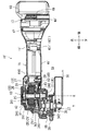
次に、本発明に係る電動工具としてのディスクグラインダの第1の実施の形態について、図1〜図3を参照しながら説明する。図1〜図3に示すディスクグラインダ10は、ユーザが手で持って加工作業を行うための手持ち式のディスクグラインダである。図1の斜視図は、第1の実施の形態のディスクグラインダ10を斜視にて示している。また、図2の内部構造断面図は、図1の(II)-(II)断面矢視を示している。また、図3の内部構造断面図は、図1の(III)-(III)断面矢視を示している。なお、このディスクグラインダ10を説明するにあたっては、図中に記載される方向を用いて説明する。このディスクグラインダ10は、概略、工具本体11と2つの充電式バッテリ90とを有して構成される。この工具本体11は、図1〜図3に示すように前側から、駆動部13と、ハンドル部15と、バッテリ装着部17とを有して構成される。
[First Embodiment]
Next, a first embodiment of a disc grinder as an electric tool according to the present invention will be described with reference to FIGS. A
駆動部13は、モータ部20とギヤ部30とを有する。モータ部20は、モータハウジング21にアウタロータ式のブラシレスDCモータ22を内装して構成される。モータハウジング21は、ブラシレスDCモータ22を収容する金属製の椀形にて形成される。具体的には、モータハウジング21は、アルミニウムを材料にして成形されている。モータハウジング21は、ブラシレスDCモータ22を支持すると共に、ギヤハウジング31やハンドルハウジング41と連結される。ブラシレスDCモータ22は、本発明に係る電動モータに相当する。ブラシレスDCモータ22は、充電式バッテリ90から供給される電力によりモータ軸25を回転駆動させる。
The
モータ軸25は、上側ベアリング241と下側ベアリング242とにより回転可能に支持される。これら上側ベアリング241と下側ベアリング242とはボールベアリングにて構成される。モータハウジング21は、モータ軸25の上側ベアリング241と、次に説明する出力軸35の上側ベアリング341とを支持する。これに対し、次に説明するギヤハウジング31は、モータ軸25の下側ベアリング242と、出力軸35の下側ベアリング342を支持する。
The
ブラシレスDCモータ22は、概略、モータハウジング21に支持されるステータ26と、モータ軸25に支持されるアウタロータ27とを有する。ステータ26は、ステータコア261とステータコイル262とを有する。ステータコア261は、モータハウジング21にて支持される。ステータコイル262は、電力が供給されて磁界を発生させる巻線にて構成されてステータコア261にて支持される。アウタロータ27は、ステータ26の外周側に配置され、ステータコア261の上側でモータ軸25と一体となっている。アウタロータ27の下側には、アウタロータ27の回転位置を検出するセンサ基板28が設けられている。モータ軸25の上部には、冷却ファン29が取り付けられている。冷却ファン29は、モータ軸25と一体に回転することにより、ステータ26が配置される下側から吸気してモータ軸25の遠心方向に排気する。この冷却ファン29の排気風は、モータハウジング21に設けられる排気口211から外部に排気される。
The
ギヤ部30は、ギヤハウジング31に減速ギヤユニット32を内装して構成される。ギヤハウジング31は、モータハウジング21の下側で、螺子部材19を介してモータハウジング21と連結される。ギヤハウジング31は、減速ギヤユニット32を収容しながらモータ軸25の下側ベアリング242と出力軸35の下側ベアリング342とを支持する。減速ギヤユニット32は、平歯車(ヘリカルギヤ)にて互いに噛合するモータギヤ331と減速ギヤ332とを有する。この減速ギヤユニット32は、毎分12000回転のモータ軸25の回転を、毎分6000〜8000回転に減速している。モータギヤ331は、モータ軸25と一体回転するようにモータ軸25に一体に取り付けられている。
The
減速ギヤ332は、出力軸35と一体回転するように出力軸35に一体に取り付けられている。減速ギヤ332は、モータギヤ331に比して歯数が多い大径にて構成される。このため、モータギヤ331の回転駆動は、減速ギヤ332に対して減速して伝達される。つまり、減速ギヤ332は、モータギヤ331と噛合してモータ軸25の回転駆動を出力軸35に減速して伝達する。回転駆動が伝達された出力軸35は、取り付けられた円形の砥石Bを回転させて回転出力する。
The
出力軸35は、上側ベアリング341と下側ベアリング342とにより回転可能に支持される。これら上側ベアリング341と下側ベアリング342とはボールベアリングにて構成される。ギヤハウジング31は、モータ軸25の下側ベアリング242と、出力軸35の下側ベアリング342とを支持する。出力軸35の下端には、先端工具としての円形の砥石Bが取り付けられる。この砥石Bは、把持機構37を介して出力軸35に取り付けられている。この砥石Bは、出力軸35と一体回転する。この砥石Bは、前側部Cを研削対象に押し付けることにより研削対象を研削する。なお、モータ軸25の回転軸線Xは鉛直方向となる上下方向と一致しているので、ブラシレスDCモータ22の水平方向の重心位置は、モータ軸25の回転軸線Xの線上に位置されることとなる。
The
ここで、モータギヤ331と減速ギヤ332とは、互いに平歯車にて構成されて互いに噛合される。すなわち、モータギヤ331はモータ軸25に対して平行に歯が切られており、減速ギヤ332は出力軸35に対して平行に歯が切られている。このため、モータギヤ331と減速ギヤ332とが互いに噛合している状態では、互いの回転軸となるモータ軸25と出力軸35とは、互いに平行方向となる上下方向に延びるように配置されている。つまり、モータ軸25の回転軸線Xと出力軸35の回転軸線Yとは互いに平行に配置されるように、ブラシレスDCモータ22と減速ギヤユニット32との配置が設定されている。つまり、モータ軸25の回転軸線Xが延びる方向と同じ方向で出力軸35の回転軸線Yが延ばされるように、ブラシレスDCモータ22と減速ギヤ332との互いの配置関係が設定されている。また、ブラシレスDCモータ22は、砥石Bが取り付けられる出力軸35に対して、バッテリ装着部17Aおよびハンドル部15Aよりも近づいた位置に設定されている。
Here, the
図示符号38は、加工対象から生ずる粉塵の飛散を抑えるホイールカバーである。このホイールカバー38は、クランプ機構39を介してギヤハウジング31に取り付けられている。なお、今回では図示を省略したが、ギヤハウジング31には、砥石Bを交換するためのシャフトロック機構が設けられている。このシャフトロック機構は、減速ギヤ332の回転をギヤハウジング31にて相対的にロックし、砥石Bの把持する把持機構37を緩ませ操作や締付け操作を行えるようにする。また、上記したモータハウジング21の左右両側には、サブグリップ(例えば図5における符号40)を取付け可能とするサブグリップ装着部36が設けられている。つまり、このディスクグラインダ10は、いわゆるツーハンドルタイプのディスクグラインダとなっている。
上記したブラシレスDCモータ22と減速ギヤユニット32との配置関係は、相対的に上下の関係で並べられるように配置されている。つまり、減速ギヤユニット32は、出力軸35に対して相対的に上側の位置に配置されている。また、ブラシレスDCモータ22は、減速ギヤユニット32に対して相対的に上側の位置に配置されている。ただ、モータギヤ331と減速ギヤ332とは前後方向で噛合している。このため、モータギヤ331の回転軸であるモータ軸25と、減速ギヤ332の回転軸である出力軸35とは、後ろ前の関係でずらされている。つまり、ブラシレスDCモータ22と減速ギヤユニット32とは、後ろ前の関係でずらされて配置されている。
The arrangement relationship between the
駆動部13の後側には、ハンドル部15が連結されている。ハンドル部15は、ハンドルハウジング41を有する。ハンドルハウジング41は、前後方向に延びる略筒形をなしている。ハンドルハウジング41は、半割り筒形に成形された半割り樹脂部材を合体させることにより形成される。このハンドル部15には、ブラシレスDCモータ22の回転駆動を操作可能とする操作スイッチ45が設けられている。操作スイッチ45は、スイッチ本体451と、スライド体452と、操作ノブ453とを有する。スイッチ本体451は、オン入力が可能な接点スイッチにて構成される。スライド体452は、操作ノブ453の前方向のスライドに応じてスイッチ本体451に対してオン入力可能に設定される。また、操作ノブ453は、ハンドルハウジング41の上面外部に配置される。つまり、この操作スイッチ45は、ユーザが工具本体11の上側でスイッチ操作できるように設定されている。なお、ハンドル部15として設定されるハンドルハウジング41の内部は、この操作スイッチ45に関する構造のみが装置されるものとなっている。
A
ハンドル部15の後部には、充電式バッテリ90を装着させるためのバッテリ装着部17が設けられている。なお、このハンドル部15の後部は、工具本体11の後部と一致する。バッテリ装着部17は、スライド装着式の2つ充電式バッテリ90を並列してスライド装着させることができるように設定されている。すなわち、ハンドルハウジング41の後部は、左右方向に幅が拡大された幅拡大部48が設けられている。この幅拡大部48の後面には、2つのスライド装着部49が左右に並列して設けられている。
A
なお、このバッテリ装着部17が設けられる幅拡大部48の内部には、装着された充電式バッテリ90からブラシレスDCモータ22に電力を供給するためのコントローラ47が設けられている。このコントローラ47は、シャント抵抗や例えば6個のFET(field-effect transistor)回路等、各種の電気部品を装備して構成され、充電式バッテリ90から供給される電力の電圧等の制御を行う。なお、このコントローラ47の下側のハンドルハウジング41には不図示の吸気口が設けられている。つまり、上記した冷却ファン29の排気風(吸引風)により、吸気口411を通じてハンドルハウジング41の内部に外気が吸気される。吸気された外気は、コントローラ47を冷却すると共に、ステータ26(ステータコイル262)も冷却する。
A
この2つのスライド装着部49のそれぞれは、充電式バッテリ90を上から下へスライドさせることによって充電式バッテリ90が装着されるものとなっている。逆に、充電式バッテリ90のロックオフボタン91を押さえながら、下から上へ充電式バッテリ90をスライドさせると、このスライド装着部49から充電式バッテリ90を取り外すことができるようになっている。2つのスライド装着部49に装着される2つの充電式バッテリ90は、ディスクグラインダ10の電源として機能する。この2つの充電式バッテリ90は、供給電力電圧が18Vに設定されるスライド装着式の充電式バッテリとなっている。
Each of the two
上記した第1の実施の形態のディスクグラインダ10によれば、モータ軸25の回転軸線Xと出力軸35の回転軸線Yとが互いに平行となるように設定されているので、モータ軸25と出力軸35との間の距離を縮め易くすることができる。これによって、砥石Bが取り付けられる出力軸35に対してモータ軸25を近づけることができて、ブラシレスDCモータ22の重心位置を出力軸35に近づけることができる。したがって、回転される砥石Bの前側部Cを研削対象に当て易くして、ディスクグラインダ10としての工具操作性を高めることができる。また、上記した第1の実施の形態のディスクグラインダ10によれば、モータギヤ331と減速ギヤ332とが平歯車(ヘリカルギヤ)にて噛合されて出力軸35に駆動伝達されている。これによって、減速ギヤユニット32を安価に構成することができると共に減速ギヤユニット32の耐久性も向上させることができる。
According to the
また、上記した第1の実施の形態のディスクグラインダ10によれば、充電式バッテリ90は工具本体11の後部にて上から下へスライドさせることによって装着される。また、バッテリ装着部17が設けられる幅拡大部48にコントローラ47が収容されている。ここで、これらバッテリ装着部17やコントローラ47が配置される部分の前側にハンドル部15が設定される。これによって、ディスクグラインダ10の前後長を短くすることができて、工具操作性を高めることができる。また、このディスクグラインダ10にあっては、前部にはモータ部20とギヤ部30とが配置され、後部には充電式バッテリ90とコントローラ47とが配置される。これによって、このディスクグラインダ10によれば、ディスクグラインダ10の前後の中間に配置されるハンドル部15をユーザが持つことによって、まるで鉄アレイのように前後で重量がバランスされることとなる。これによって、前後に重量がバランスされた工具操作性が高められたディスクグラインダ10とすることができる。
Further, according to the
また、ハンドル部15は、バッテリ装着部17やコントローラ47が設けられない簡素な構成とすることができる。つまり、ハンドル部15の外形は、例えば単純に細く形成するなど、ユーザの手で握られ易くなる形状に設定することができる。したがって、上記した第1の実施の形態のディスクグラインダ10によれば、ユーザにグリップが握り易くされて工具操作性を高めることができる。また同様に、充電式バッテリ90やコントローラ47が工具本体11の後部に配置され、且つモータ軸25が出力軸35の近くで縦置きにされているので、ユーザの手握り位置を出力軸35により近くすることができる。これによって、ユーザの手握り位置が砥石Bの前側部Cに近くなり、この前側部Cの操作精度を高めることができて、研削作業時の工具操作性を高めることができる。更に言えば、上記した第1の実施の形態のディスクグラインダ10によれば、ハンドル部15の嵩張りが減らされているので、ハンドル部15の上下位置はディスクグラインダ10の下端から図2に示すS1の距離が隔てられて設定されることとなる。これによって、砥石Bの前側部Cとユーザの手握り位置との間で角度が付け易くなって、研削作業時の工具操作性を高めることができる。
Further, the
また、上記した第1の実施の形態のディスクグラインダ10によれば、駆動部13に、モータ部20とギヤ部30とを集約させたことにより、ハンドル部15の内部に装置される構成が減らされる。具体的に言えば、ハンドルハウジング41の内部には、これまで装置されていたブラシレスDCモータ22が無くされ、操作スイッチ45のみだけが装置されることとなる。これによって、ハンドルハウジング41を小さくすることができて、ハンドル部15の外周径を細くすることができる。したがって、ユーザにとって細く握り易くされたハンドル部15とすることができ、操作性に優れたディスクグラインダ10とすることができる。また、このようなディスクグラインダ10にあっては、ハンドル部15の内部に装置される構成を減らされているので、次に説明する第2の実施の形態のような防振構造80を採用することができる。
Further, according to the
[第2の実施の形態]
次に、上記した第1の実施の形態のディスクグラインダ10の変形例となる第2の実施の形態のディスクグラインダ10´について説明する。すなわち、図4および図5の内部構造断面図は、図2および図3の変形例となるディスクグラインダ10´を示している。この第2の実施の形態のディスクグラインダ10´は、上記した第1の実施の形態のディスクグラインダ10と比較して、大まかにハンドルハウジング41´に関しての構造が相違する例であり、その他の構造については上記した第1の実施の形態のディスクグラインダ10と同様に構成される。このため、このディスクグラインダ10´において、上記した第1の実施の形態のディスクグラインダ10と同様に構成される箇所については、図面に同一符号を付して、その説明を省略するものとする。また、このディスクグラインダ10´において、上記した第1の実施の形態のディスクグラインダ10と同類に機能される箇所については、上記と同一符号に末尾に『´』が付して説明するものとする。
[Second Embodiment]
Next, a
この第2の実施の形態の工具本体11´は、上記した第1の実施の形態のハンドルハウジング41とは相違するハンドルハウジング41´を有する。すなわち、この第2の実施の形態のハンドルハウジング41´は、モータハウジング21´を覆う形状を有して成形される。具体的には、ハンドルハウジング41´には、第1の実施の形態のハンドルハウジング41と比較して、ハウジング本体410から前方に延出される延出上側部42および延出下側部43が設けられている。これら延出上側部42および延出下側部43は、モータハウジング21´の外周形状に合わせて成形される。具体的には、延出上側部42は、モータハウジング21´を上側から覆うように、モータハウジング21´の上面形状を沿った形状を有して成形される。また、延出下側部43も、モータハウジング21´を下側から覆うように、モータハウジング21´の下面形状を沿った形状を有して成形される。また、ハンドルハウジング41´は、モータハウジング21´の前面および左右両側面も覆う形状を有しており、延出上側部42および延出下側部43と連なって成形されている。なお、このハンドルハウジング41´の前面には、冷却ファン29からの排気風を外部に排気するための排気口211´が設けられている。ちなみに、この冷却ファン29は、モータ軸25の下部に取り付けられている。また、アウタロータ27の回転位置を検出するセンサ基板28については、アウタロータ27の上側に設けられている。
The tool main body 11 'of the second embodiment has a handle housing 41' different from the
ハンドルハウジング41´に設けられる操作スイッチ45´は、ユーザが工具本体11の左側でスイッチ操作できるように設定されている。すなわち、操作スイッチ45´は、スイッチ本体451´と、スライド体452´と、操作ノブ453´と、回動入力部材455とを有する。この第2の実施の形態の操作ノブ453´は、ハンドルハウジング41´の左側面外部に配置される。回動入力部材455は、スライド体452のスライドを受けて回動され、この回動により回動入力部材455はスイッチ本体451にオン入力をするように構成される。なお、スイッチ本体451´およびスライド体452´は、上記した第1の実施の形態と同様に構成される。ハンドル部15として設定されるハンドルハウジング41´の内部にあっても、この操作スイッチ45´に関する構造のみが装置されるものとなっている。また、ハンドルハウジング41´の後部にも、バッテリ装着部17が設けられる幅拡大部48´が設けられている。この幅拡大部48´は、上記した第1の実施の形態の幅拡大部48よりも、滑らかに左右方向に幅が拡大されている。
An operation switch 45 ′ provided on the
ところで、この工具本体11´には、手で握られるハンドル部15への振動伝達を減らす防振構造80が設けられる。この防振構造80は、上記したモータハウジング21´とハンドルハウジング41´との間に、防振ゴム81,82,83,84が介装されることにより構成される。これら防振ゴム81,82,83,84は、同一の素材となる弾性を有する樹脂シートにて形成される。具体的には、図4に示すように、モータハウジング21´の上面とハンドルハウジング41´の延出上側部42との間には、上側防振ゴム81が介装される。また、モータハウジング21´の下面とハンドルハウジング41´の延出下側部43との間にも、下側防振ゴム82が介装される。これら上側防振ゴム81および下側防振ゴム82は、モータハウジング21´の外周形状と、このモータハウジング21´の外周形状に沿って成形されるハンドルハウジング41´の形状とに挟み込まれるようにして両者の間に介装される。この上側防振ゴム81および下側防振ゴム82は、モータハウジング21´とハンドルハウジング41´との両者に押圧されるようにして両者の間に介装される。
By the way, the
また、図5に示すように、モータハウジング21´の後部には、ハンドルハウジング41´との間に右側防振ゴム83および左側防振ゴム84を介装されてある。なお、これら右側防振ゴム83と左側防振ゴム84とが介装される箇所は、ハンドルハウジング41´が延びる中心軸線に対して、左右対称で構成される。モータハウジング21´の後部には、右側凹部85および左側凹部86がモータハウジング21´と一体に設けられ、これら右側凹部85および左側凹部86と対面するハンドルハウジング41´の内周面には、右側凸部441および左側凸部442がハンドルハウジング41´と一体に設けられている。右側凹部85は、右側に向いて凹んだ形状を有して形成され、右側凸部441は、右側凹部85に入り込むように突出されたリブ形状を有して形成される。また、左側凹部86は、左側に向いて凹んだ形状を有して形成され、左側凸部442は、左側凹部86に入り込むように突出されたリブ形状を有して形成される。
Further, as shown in FIG. 5, a right
ここで、右側凹部85と右側凸部441との間には右側防振ゴム83が介装されており、左側凹部86と左側凸部442との間には左側防振ゴム84が介装されている。右側防振ゴム83は、右側凹部85と右側凸部441との間で両者に押圧されるようにして両者に密着しながら介装される。左側防振ゴム84は、左側凹部86と左側凸部442との間で、両者に押圧されるようにして両者に密着しながら介装される。このように、防振ゴム81,82,83,84が介装されていると、駆動部13に生ずる振動がハンドル部15に伝達されるにあたって、この振動が抑えられて駆動部13からハンドル部15に伝達されることとなる。
Here, a right
[第3の実施の形態]
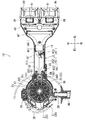
次に、本発明に係る電動工具としてのディスクグラインダの第3の実施の形態について、図6〜図8を参照しながら説明する。図6の斜視図は、第3の実施の形態のディスクグラインダ10Aを斜視にて示している。また、図7の内部構造断面図は、図6の(VII)-(VII)断面矢視を示している。また、図8の内部構造断面図は、図6の(VIII)-(VIII)断面矢視を示している。この第3の実施の形態のディスクグラインダ10Aは、第1の実施の形態のディスクグラインダ10と比較して、ハンドル部15の配置位置とバッテリ装着部17との配置位置とが入れ違いになっている。
[Third Embodiment]
Next, a third embodiment of a disc grinder as an electric power tool according to the present invention will be described with reference to FIGS. The perspective view of FIG. 6 shows the
このため、以下に第3の実施の形態のディスクグラインダ10を説明するにあたっては、第1の実施の形態のディスクグラインダ10と同一に構成される箇所については、第1の実施の形態を説明した際に用いた符号を図面に付して説明を省略する。また、第3の実施の形態のディスクグラインダ10において、第1の実施の形態のディスクグラインダ10に類して構成される箇所については、第1の実施の形態を説明した際に用いた符号末尾に‘A’を追加して以下に説明するものとする。
For this reason, in the following description of the
すなわち、第3の実施の形態のディスクグラインダ10Aは、駆動部13に関する構成については、第1の実施の形態のディスクグラインダ10と同一に構成される。この第3の実施の形態のディスクグラインダ10Aでは、駆動部13の後側にはバッテリ装着部17Aが設けられており、このバッテリ装着部17Aの後側にはハンドル部15Aが設けられている。これらバッテリ装着部17Aとハンドル部15Aとの両者は、共にハンドルハウジング41Aにて構成される。すなわち、ハンドルハウジング41Aの前部下面にはバッテリ装着部17Aが設けられており、ハンドルハウジング41Aの後部にはハンドル部15Aが設けられている。
That is, the
第3の実施の形態のバッテリ装着部17Aにあっても、上記した第1の実施の形態と同様に、スライド装着式の2つ充電式バッテリ90を並列してスライド装着させることができるように設定されている。すなわち、ハンドルハウジング41の前部下面には、左右方向に幅が拡大された幅拡大部48Aが設けられている。この幅拡大部48の下面には、2つのスライド装着部49Aが前後に並列して設けられている。
Even in the
この2つのスライド装着部49のそれぞれは、充電式バッテリ90を左から右へスライドさせることによって充電式バッテリ90が装着されるものとなっている。逆に、充電式バッテリ90のロックオフボタン91を押さえながら、右から左へ充電式バッテリ90をスライドさせると、このスライド装着部49から充電式バッテリ90を取り外すことができるようになっている。これら2つのスライド装着部49Aに装着される2つの充電式バッテリ90は、上記した第1の実施の形態の充電式バッテリ90と同様、供給電力電圧が18Vに設定されるスライド装着式の充電式バッテリとなっている。
Each of the two
この2つのスライド装着部49Aの後側にハンドル部15Aが設けられている。ハンドル部15Aは、ハンドルハウジング41Aの後部にて構成される。つまり、ハンドル部15Aは、工具本体11の最後部に設けられている。ハンドル部15Aは、バッテリ装着部17Aから後側に、手で握ることが可能なグリップ形状を有して延びている。具体的には、ハンドル部15Aは、バットグリップのように手で握ることが可能な柱状部51を有して延びている。この柱状部51の後端には、下側に向けて張り出されてグリップエンド部52が設けられている。このグリップエンド部52は、柱状部51を握る手の抜けを抑える作用を奏する。
A
柱状部51の前側には、操作スイッチ53が設けられている。この操作スイッチ53は、ブラシレスDCモータ22の回転駆動を操作可能とするスイッチである。操作スイッチ53は、柱状部51を握った手の人差し指や中指で、引き操作を可能とする配置位置および操作構造を有する。操作スイッチ53は、スイッチ本体55と、操作トリガ57とを有する。スイッチ本体55は、オン入力が可能な接点スイッチにて構成される。操作トリガ57には、ロックオフボタン56が設けられている。このため、柱状部51を握った手の親指でロックオフボタン56を押さえ込み、人差し指や中指で操作トリガ57を引き操作すると、操作トリガ57は引き回動される。引き回動された操作トリガ57は、スイッチ本体55にオン入力するものとなっている。
An
なお、第3の実施の形態のディスクグラインダ10Aにあっても、上記した第1の実施の形態のディスクグラインダ10と同様に、モータ軸25の回転軸線Xと出力軸35の回転軸線Yとは互いに平行に配置されるように、ブラシレスDCモータ22と減速ギヤユニット32との配置が設定されている。また、ブラシレスDCモータ22は、砥石Bが取り付けられる出力軸35に対して、バッテリ装着部17Aおよびハンドル部15Aよりも近づいた位置に設定されている。
Even in the
この第3の実施の形態のディスクグラインダ10Aによれば、ブラシレスDCモータ22は出力軸35に対してバッテリ装着部17Aよりも近づいた位置に設定されているので、ブラシレスDCモータ22の重心位置をバッテリ装着部17Aに装着された充電式バッテリ90の重心位置よりも出力軸35に近づけることができる。また、この第3の実施の形態のディスクグラインダ10Aによれば、ハンドル部15Aは工具本体11の後部に設定されているので、サブグリップ装着部36にサブグリップ(不図示)を取り付けた場合に、ハンドル部15Aとサブグリップとの間隔を長く設けて従来どおりの持ち方をすることができる。加えて、ハンドル部15Aとサブグリップとの間に2つ充電式バッテリ90が配置されるので、ユーザが両手で持った場合の重量がバランスされ易い。更に、モータ軸25が出力軸35の近くで縦置きにされているので、工具本体11の前部がコンパクトになっている。これによって、従来どおりのツーハンドルの使用感を有しながらも、さらに砥石Bの前側部Cの位置を細やかに操作し易くなり工具操作性を高めることができる。
According to the
また、バッテリ装着部17Aについても、出力軸35に対してハンドル部15Aよりも近づいた位置に設定されているので、バッテリ装着部17Aに装着された充電式バッテリ90の重心位置をハンドル部15Aよりも出力軸35に近づけることができる。これによって、ブラシレスDCモータ22の重心位置と充電式バッテリ90の重心位置とを、この順で出力軸35に近づけることができる。したがって、工具重心位置を回転される砥石Bの研削位置に近づけることができて、研削対象に回転される砥石Bの前側部Cを当て易くして工具操作性を高めることができる。また、上記した第3の実施の形態のディスクグラインダ10Aによれば、装着される充電式バッテリ90の下端は、ディスクグラインダ10の下端と図7に示すS2の距離を有している。これによって、工具本体11の後部に設定されるハンドル部15Aの上下方向の位置を変え易くして、研削作業時の工具操作性を高めることができる。また、充電式バッテリ90の下端は、ホイールカバー38の上端と図7に示すS3の距離を有しているので、充電式バッテリ90の着脱操作も行い易いものとなっている。
Further, since the
[第4の実施の形態]
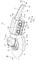
次に、本発明に係る電動工具としてのディスクグラインダの第4の実施の形態について、図9〜図11を参照しながら説明する。図9の斜視図は、第4の実施の形態のディスクグラインダ10Bを斜視にて示している。また、図10の内部構造断面図は、図9の(X)-(X)断面矢視を示している。また、図11の内部構造断面図は、図9の(XI)-(XI)断面矢視を示している。この第4の実施の形態のディスクグラインダ10Bは、第3の実施の形態のディスクグラインダ10Aの変形例となっている。すなわち、この第4の実施の形態のディスクグラインダ10Bは、第3の実施の形態のディスクグラインダ10Aと比較して駆動部13Bの構成が相違する。このため、以下に第4の実施の形態のディスクグラインダ10Bを説明するにあたっては、第3の実施の形態のディスクグラインダ10と同一に構成される箇所については、第3の実施の形態を説明した際に用いた符号を図面に付して説明を省略する。
[Fourth Embodiment]
Next, a fourth embodiment of a disc grinder as an electric power tool according to the present invention will be described with reference to FIGS. The perspective view of FIG. 9 shows the
すなわち、この第4の実施の形態の駆動部13Bも、モータ部60とギヤ部70とを有する。モータ部60は、モータハウジング61にインナロータ式のブラシレスDCモータ62を内装して構成される。モータハウジング61は、ブラシレスDCモータ22を収容する金属製の筒形にて形成される。モータハウジング61は、ブラシレスDCモータ62を支持すると共に、ギヤハウジング71やハンドルハウジング41Aと連結される。ブラシレスDCモータ62は、本発明に係る電動モータに相当する。ブラシレスDCモータ62は、充電式バッテリ90から供給される電力によりモータ軸65を回転駆動させる。
That is, the
モータ軸65は、後側ベアリング641と前側ベアリング642とにより回転可能に支持される。これら後側ベアリング641と前側ベアリング642とはボールベアリングにて構成される。なお、後側ベアリング641はモータハウジング61に支持されており、前側ベアリング642はギヤハウジング71に支持されている。ブラシレスDCモータ62は、概略、モータハウジング61に支持されるステータ66と、モータ軸65に支持されるインナロータ67とを有する。インナロータ67は、ステータ66の内周側に配置されている。インナロータ67の後側には、インナロータ67の回転位置を検出するセンサ基板68が設けられている。モータ軸65の前部には、冷却ファン69が取り付けられている。冷却ファン69は、モータ軸65と一体に回転することにより、ステータ66を冷却し、ギヤハウジング71に設けられる排気口211から外部に排気される。
The
ギヤ部70は、ギヤハウジング71に減速ギヤユニット72を内装して構成される。ギヤハウジング71は、モータハウジング61の前側で、螺子部材19を介してモータハウジング61と連結される。ギヤハウジング71は、減速ギヤユニット72を収容しながらモータ軸65の前側ベアリング642を支持する。また、ギヤハウジング71は、出力軸75の上側ベアリング742および下側ベアリング742を支持する。減速ギヤユニット72は、かさ歯車(ベベルギヤ)により互いに噛合するモータギヤ731と減速ギヤ732とを有する。モータギヤ731は、モータ軸65と一体回転するようにモータ軸65に一体に取り付けられている。
The
減速ギヤ732は、出力軸75と一体回転するように出力軸75に一体に取り付けられている。これらモータギヤ731と減速ギヤ732とは、互いに、はすば歯車として構成される。減速ギヤ732は、モータギヤ731に比して歯数が多く構成される。このため、モータギヤ731の回転駆動は、減速ギヤ732に対して減速して伝達される。つまり、減速ギヤ732は、モータギヤ731と噛合してモータ軸65の回転駆動を出力軸75に減速して伝達する。回転駆動が伝達された出力軸75は、取り付けられた円形の砥石Bを回転させて回転出力する。
The
出力軸75は、上側ベアリング741と下側ベアリング742とにより回転可能に支持される。これら上側ベアリング741と下側ベアリング742とはボールベアリングにて構成される。出力軸75の下端には、先端工具としての円形の砥石Bが取り付けられる。この砥石Bは、把持機構37を介して出力軸75に取り付けられている。この砥石Bは、出力軸75と一体回転する。この砥石Bは、前側部Cを研削対象に押し付けることにより研削対象を研削する。なお、この第4の実施の形態のディスクグラインダ10Bにあっても、バッテリ装着部17Aが出力軸75に対してハンドル部15Aよりも近づいた位置に設定されている。
The
この第4の実施の形態のディスクグラインダ10Bによれば、バッテリ装着部17Aに装着された充電式バッテリ90の重心位置をハンドル部15Aよりも出力軸75に近づけることができる。これによって、ブラシレスDCモータ62の重心位置と充電式バッテリ90の重心位置とを、この順で出力軸35に近づけることができる。したがって、工具重心位置を、回転される砥石Bの研削位置に近づけることができて、研削対象に回転される砥石Bの前側部Cを当て易くして工具操作性を高めることができる。また、上記した第4の実施の形態のディスクグラインダ10Bによれば、装着される充電式バッテリ90の下端は、ディスクグラインダ10の下端と図10に示すS4の距離を有している。これによって、工具本体11の後部に設定されるハンドル部15Aの上下方向の位置を変え易くして、研削作業時の工具操作性を高めることができる。
According to the
なお、本発明に係る電動工具としては、上記したディスクグラインダの例に限定されるものではなく、手で持って作業を行う手持ち式の電動工具であれば、上記した実施の形態の構成を適宜に応用して構成することができる。すなわち、本発明に係る電動工具としては、上記したディスクグラインダに限定されることなく、例えばディスクサンダ、ポリッシャ、マルチツール等の研削、研磨、磨き、つや出し等の各種作業を行う各種の手持ち式の電動工具に応用することができる。また、本発明に係る充電式バッテリとしては、上記した実施の形態における充電式バッテリ90の例に限定されることなく、適宜の電圧にて設計される充電式バッテリに置き換えることができる。また、上記した実施の形態にあっては充電式バッテリ90が2つ設定される例を説明するものであったが、本発明に係る充電式バッテリとしては、これに限定されることなく、1つのみや3つ4つで設定されるものであってもよい。
The power tool according to the present invention is not limited to the example of the above-described disc grinder, and any configuration of the above-described embodiment can be used as long as the power tool is a hand-held power tool that is held by hand. It can be applied and configured. That is, the power tool according to the present invention is not limited to the above-described disk grinder, but various hand-held types that perform various operations such as grinding, polishing, polishing, polishing, etc., such as a disk sander, polisher, and multi-tool. It can be applied to power tools. Further, the rechargeable battery according to the present invention is not limited to the example of the
10,10A ディスクグラインダ(電動工具)
11 工具本体
13 駆動部
15,15A ハンドル部
17,17A バッテリ装着部
19 螺子部材
20 モータ部
21 モータハウジング
211 排気口
22 ブラシレスDCモータ(電動モータ)
241 上側ベアリング
242 下側ベアリング
25 モータ軸
26 ステータ
261 ステータコア
262 ステータコイル
27 アウタロータ
28 センサ基板
29 冷却ファン
30 ギヤ部
31 ギヤハウジング
32 減速ギヤユニット
331 モータギヤ
332 減速ギヤ
341 上側ベアリング
342 下側ベアリング
35 出力軸
36 サブグリップ装着部
37 把持機構
38 ホイールカバー
39 クランプ機構
41,41A ハンドルハウジング
45 操作スイッチ
451 スイッチ本体
452 スライド体
453 操作ノブ
47 コントローラ
48,48A 幅拡大部
49,49A スライド装着部
51 柱状部
52 グリップエンド部
53 操作スイッチ
55 スイッチ本体
56 ロックオフボタン
57 操作トリガ
90 充電式バッテリ
91 ロックオフボタン
B 砥石
X 回転軸線
Y 回転軸線
10,10A disc grinder (power tool)
DESCRIPTION OF
241
Claims (9)
前記モータを収容するモータハウジング(21‘)と、
前記モータハウジングに繋がるハンドルハウジング(41‘)と、
前記モータハウジングと、前記ハンドルハウジングの間に配置される防振構造(80)と、を有する電動工具であって、
前記モータのモータ軸の回転駆動は、減速部により減速されて出力軸(35)に伝達され、前記減速部はケースに収容されており、該ケースは前記モータハウジングの下側に連結されており、かつ該ケースは、前記モータハウジングに対して前側へはみ出して配置されるとともに、前記防振構造よりも下方に配置されている電動工具。 A motor (22) having a motor shaft (25) vertically disposed and extending in the vertical direction;
A motor housing (21 ′) for housing the motor;
A handle housing (41 ′) connected to the motor housing;
An electric tool having the motor housing and a vibration isolation structure (80) disposed between the handle housing ,
The rotational drive of the motor shaft of the motor is decelerated by the speed reduction unit and transmitted to the output shaft (35). The speed reduction unit is accommodated in a case, and the case is connected to the lower side of the motor housing. The power tool is disposed so as to protrude forward relative to the motor housing and disposed below the vibration-proof structure .
前記ハンドルハウジングは、凸部(441,442)を有しており、
前記凹部と前記凸部の間に、防振ゴム(83,84)が配置されている請求項1又は2記載の電動工具。 The motor housing has recesses (85, 86);
The handle housing has convex portions (441, 442),
The electric tool according to claim 1 or 2, wherein a vibration-proof rubber (83, 84) is disposed between the concave portion and the convex portion.
前記ケースは、ギヤハウジング(31)である請求項1〜3の何れか1項に記載の電動工具。 The reduction part is a reduction gear unit;
The electric tool according to any one of claims 1 to 3 , wherein the case is a gear housing (31).
前記ハンドルハウジングは、前記ギヤハウジングを覆わない様に構成されている請求項4又は5記載の電動工具。 The handle housing covers at least a portion of the motor housing;
The power tool according to claim 4 or 5 , wherein the handle housing is configured not to cover the gear housing.
防振ゴム(81,82)は、前記モータの前方上部及び後方下部に配置される請求項1〜6の何れか1項に記載の電動工具。 The output shaft is disposed in front of the rotation shaft of the motor,
Anti-vibration rubber (81, 82) is an electric tool given in any 1 paragraph of Claims 1-6 arranged at the front upper part and back lower part of said motor.
前記モータの回転軸の後方に、防振ゴム(82)が配置されている請求項1〜7の何れか1項に記載の電動工具。 Anti-vibration rubber (81) is disposed above the output shaft,
The electric tool according to any one of claims 1 to 7, wherein an anti-vibration rubber (82) is disposed behind the rotating shaft of the motor.
前記モータを収容するモータハウジング(21‘)と、
前記モータハウジングに繋がるハンドルハウジング(41‘)と、
前記モータハウジングに繋がり、前記ハンドルハウジングから下方に露出するギヤハウジング(31)と、
前記ギヤハウジングに収容される減速ギヤユニットと、
前記減速ギヤユニットに繋がる出力軸と、
前記モータハウジングと、前記ハンドルハウジングの間に配置される防振構造(80)と、を有し、
前記減速ギヤユニットは、前記防振構造よりも下方に配置され、
前記モータ軸は、前記出力軸よりも後方に配置される電動工具。
A motor (22) having a motor shaft (25) vertically disposed and extending in the vertical direction;
A motor housing (21 ′) for housing the motor;
A handle housing (41 ′) connected to the motor housing;
A gear housing (31) connected to the motor housing and exposed downward from the handle housing;
A reduction gear unit housed in the gear housing;
An output shaft connected to the reduction gear unit;
The motor housing and an anti-vibration structure (80) disposed between the handle housing,
The reduction gear unit is disposed below the vibration-proof structure,
The motor shaft is an electric tool arranged behind the output shaft .
Priority Applications (5)
| Application Number | Priority Date | Filing Date | Title |
|---|---|---|---|
| JP2014224954A JP6408870B2 (en) | 2014-11-05 | 2014-11-05 | Electric tool |
| PCT/JP2015/080095 WO2016072306A1 (en) | 2014-11-05 | 2015-10-26 | Electric tool |
| CN201580060485.6A CN107107324A (en) | 2014-11-05 | 2015-10-26 | Electric tool |
| DE112015005012.4T DE112015005012T5 (en) | 2014-11-05 | 2015-10-26 | Electrically powered tool |
| US15/524,059 US20170334056A1 (en) | 2014-11-05 | 2015-10-26 | Electric tool |
Applications Claiming Priority (1)
| Application Number | Priority Date | Filing Date | Title |
|---|---|---|---|
| JP2014224954A JP6408870B2 (en) | 2014-11-05 | 2014-11-05 | Electric tool |
Publications (3)
| Publication Number | Publication Date |
|---|---|
| JP2016087740A JP2016087740A (en) | 2016-05-23 |
| JP2016087740A5 JP2016087740A5 (en) | 2017-07-20 |
| JP6408870B2 true JP6408870B2 (en) | 2018-10-17 |
Family
ID=55909032
Family Applications (1)
| Application Number | Title | Priority Date | Filing Date |
|---|---|---|---|
| JP2014224954A Active JP6408870B2 (en) | 2014-11-05 | 2014-11-05 | Electric tool |
Country Status (5)
| Country | Link |
|---|---|
| US (1) | US20170334056A1 (en) |
| JP (1) | JP6408870B2 (en) |
| CN (1) | CN107107324A (en) |
| DE (1) | DE112015005012T5 (en) |
| WO (1) | WO2016072306A1 (en) |
Families Citing this family (27)
| Publication number | Priority date | Publication date | Assignee | Title |
|---|---|---|---|---|
| US20150328764A1 (en) | 2013-02-01 | 2015-11-19 | Makita Corporation | Power tool |
| JP6769116B2 (en) * | 2016-05-30 | 2020-10-14 | マックス株式会社 | Electric tool |
| JP7020793B2 (en) * | 2016-11-02 | 2022-02-16 | 株式会社マキタ | Electric tool |
| US10513005B2 (en) * | 2016-11-02 | 2019-12-24 | Makita Corporation | Power tool |
| JP7039209B2 (en) * | 2017-08-09 | 2022-03-22 | 株式会社マキタ | Polisher |
| JP6953252B2 (en) * | 2017-09-19 | 2021-10-27 | 株式会社マキタ | Rotating tool |
| US11007632B2 (en) * | 2017-12-01 | 2021-05-18 | Makita Corporation | Power tool |
| KR101915494B1 (en) * | 2018-01-03 | 2018-11-09 | 계양전기 주식회사 | Electric Power Grinder Having Function of Battery Charging using the Thermoelement |
| DE102018208048A1 (en) * | 2018-05-23 | 2019-11-28 | Robert Bosch Gmbh | Hand tool |
| CN108908027A (en) * | 2018-06-06 | 2018-11-30 | 浙江开创电气有限公司 | Hand-held angle grinder |
| US20210394288A1 (en) * | 2018-12-12 | 2021-12-23 | Hilti Aktiengesellschaft | Reciprocating saw |
| DE202019103132U1 (en) * | 2019-06-04 | 2020-09-07 | Robel Bahnbaumaschinen Gmbh | Cut-off machine for cutting through a rail of a track |
| US11396078B2 (en) * | 2019-06-10 | 2022-07-26 | Makita Corporation | Grinder |
| IT201900006430A1 (en) * | 2019-06-11 | 2020-12-11 | Andrea Teri | Electric device in direct current, portable for sanding and polishing of various surfaces, working with two batteries and supply of water from the device. |
| CN112077799A (en) * | 2019-06-14 | 2020-12-15 | 南京德朔实业有限公司 | Electric tool |
| WO2020250716A1 (en) * | 2019-06-14 | 2020-12-17 | 工機ホールディングス株式会社 | Power tool |
| US11865679B2 (en) | 2019-10-11 | 2024-01-09 | Ingersoll-Rand Industrial U.S., Inc. | Battery powered impact wrench |
| EP3812089A1 (en) | 2019-10-23 | 2021-04-28 | Black & Decker Inc. | Pole sander |
| JP7352445B2 (en) * | 2019-11-05 | 2023-09-28 | 株式会社マキタ | portable bandsaw |
| WO2021107827A1 (en) * | 2019-11-25 | 2021-06-03 | Husqvarna Ab | A hand-held electrically powered work tool |
| US11757330B2 (en) | 2019-12-19 | 2023-09-12 | Black & Decker, Inc. | Canned outer-rotor brushless motor for a power tool |
| US11437900B2 (en) | 2019-12-19 | 2022-09-06 | Black & Decker Inc. | Modular outer-rotor brushless motor for a power tool |
| DE102020210627A1 (en) | 2020-08-20 | 2022-02-24 | Robert Bosch Gesellschaft mit beschränkter Haftung | hand tool |
| CN114473771B (en) * | 2020-11-12 | 2023-06-20 | 南京泉峰科技有限公司 | Polishing tool |
| US11867224B2 (en) | 2021-01-27 | 2024-01-09 | Black & Decker Inc. | Locking mechanism for two telescoping poles of a power tool |
| JP2023009617A (en) * | 2021-07-07 | 2023-01-20 | 株式会社マキタ | portable band saw |
| DE102022200240A1 (en) | 2022-01-12 | 2023-07-13 | Robert Bosch Gesellschaft mit beschränkter Haftung | Grinding machine, polishing machine and second handle |
Family Cites Families (21)
| Publication number | Priority date | Publication date | Assignee | Title |
|---|---|---|---|---|
| JPS5915765B2 (en) * | 1981-10-05 | 1984-04-11 | 松下電工株式会社 | Rotary power tool gearbox |
| JPH03202283A (en) * | 1989-12-28 | 1991-09-04 | Makita Corp | Power tool |
| DE102004047808A1 (en) * | 2004-09-29 | 2006-03-30 | Robert Bosch Gmbh | Grinding hand tool machine, in particular Akkuschleifhandwerkzeugmaschine |
| SE532224C2 (en) * | 2008-02-15 | 2009-11-17 | Atlas Copco Tools Ab | Pneumatic power tool provided with indicator for working parameter values |
| DE102008040061A1 (en) * | 2008-07-02 | 2010-01-07 | Robert Bosch Gmbh | Power tool |
| JP5355999B2 (en) * | 2008-11-25 | 2013-11-27 | 株式会社マキタ | Battery pack |
| JP5382431B2 (en) * | 2009-05-29 | 2014-01-08 | 日立工機株式会社 | Electric tool |
| US8628380B2 (en) * | 2009-07-14 | 2014-01-14 | Tai-Her Yang | Direct motor-drive portable angle grinder |
| US20110081847A1 (en) * | 2009-10-05 | 2011-04-07 | Tai-Her Yang | Motor parallel transmission portable angle grinder |
| JP5432761B2 (en) * | 2010-02-12 | 2014-03-05 | 株式会社マキタ | Electric tool powered by multiple battery packs |
| JP5616104B2 (en) * | 2010-04-12 | 2014-10-29 | 株式会社マキタ | Power tools powered by battery packs and their adapters |
| JP5523905B2 (en) * | 2010-04-13 | 2014-06-18 | 株式会社マキタ | Terminal connection structure |
| DE102010027205A1 (en) * | 2010-07-06 | 2012-01-12 | C. & E. Fein Gmbh | hand tool |
| EP2647472B1 (en) * | 2010-12-02 | 2016-09-14 | Makita Corporation | Power tool |
| CN103402682B (en) * | 2011-02-28 | 2016-09-07 | 株式会社牧田 | Parting tool |
| JP5764034B2 (en) * | 2011-10-19 | 2015-08-12 | リョービ株式会社 | Electric tool |
| JP2013119129A (en) * | 2011-12-06 | 2013-06-17 | Makita Corp | Power tool |
| JP6020148B2 (en) * | 2012-03-20 | 2016-11-02 | 株式会社豊田自動織機 | Electric compressor |
| JP6016602B2 (en) * | 2012-12-10 | 2016-10-26 | 株式会社マキタ | Electric tool |
| JP6033698B2 (en) * | 2013-02-01 | 2016-11-30 | 株式会社マキタ | Electric tool |
| JP6043195B2 (en) * | 2013-02-01 | 2016-12-14 | 株式会社マキタ | Electric tool |
-
2014
- 2014-11-05 JP JP2014224954A patent/JP6408870B2/en active Active
-
2015
- 2015-10-26 CN CN201580060485.6A patent/CN107107324A/en active Pending
- 2015-10-26 WO PCT/JP2015/080095 patent/WO2016072306A1/en active Application Filing
- 2015-10-26 US US15/524,059 patent/US20170334056A1/en not_active Abandoned
- 2015-10-26 DE DE112015005012.4T patent/DE112015005012T5/en active Pending
Also Published As
| Publication number | Publication date |
|---|---|
| DE112015005012T5 (en) | 2017-08-10 |
| CN107107324A (en) | 2017-08-29 |
| WO2016072306A1 (en) | 2016-05-12 |
| US20170334056A1 (en) | 2017-11-23 |
| JP2016087740A (en) | 2016-05-23 |
Similar Documents
| Publication | Publication Date | Title |
|---|---|---|
| JP6408870B2 (en) | Electric tool | |
| JP6474764B2 (en) | Cutting machine | |
| US8716908B2 (en) | Power tool | |
| JP6043195B2 (en) | Electric tool | |
| CN106964836B (en) | Cutting machine | |
| CN107175724B (en) | Chain saw | |
| JP6403589B2 (en) | Work tools | |
| JP7145423B2 (en) | Electric tool | |
| JP7039209B2 (en) | Polisher | |
| JP2014079873A (en) | Power tool | |
| WO2014008873A1 (en) | Portable cutting tool | |
| JP2010269409A (en) | Disc grinder | |
| JP2019030946A (en) | Rechargeable polisher | |
| JP2014079874A (en) | Power tool | |
| US20230219151A1 (en) | Electric working machine | |
| JP6881037B2 (en) | Electric tool | |
| JP5463907B2 (en) | Electric tool | |
| JP6379157B2 (en) | Handheld electric disc grinder | |
| JP6480975B2 (en) | Electric tool | |
| WO2013084554A1 (en) | Electrically powered tool | |
| WO2020250716A1 (en) | Power tool | |
| JP2008264935A (en) | Handle of hand tool | |
| JP7049145B6 (en) | Electric tool | |
| JP6636578B2 (en) | Electric tool | |
| JP2017056684A (en) | Portable plane |
Legal Events
| Date | Code | Title | Description |
|---|---|---|---|
| A521 | Request for written amendment filed |
Free format text: JAPANESE INTERMEDIATE CODE: A523 Effective date: 20170607 |
|
| A621 | Written request for application examination |
Free format text: JAPANESE INTERMEDIATE CODE: A621 Effective date: 20170607 |
|
| A131 | Notification of reasons for refusal |
Free format text: JAPANESE INTERMEDIATE CODE: A131 Effective date: 20180529 |
|
| A521 | Request for written amendment filed |
Free format text: JAPANESE INTERMEDIATE CODE: A523 Effective date: 20180720 |
|
| TRDD | Decision of grant or rejection written | ||
| A01 | Written decision to grant a patent or to grant a registration (utility model) |
Free format text: JAPANESE INTERMEDIATE CODE: A01 Effective date: 20180918 |
|
| A61 | First payment of annual fees (during grant procedure) |
Free format text: JAPANESE INTERMEDIATE CODE: A61 Effective date: 20180921 |
|
| R150 | Certificate of patent or registration of utility model |
Ref document number: 6408870 Country of ref document: JP Free format text: JAPANESE INTERMEDIATE CODE: R150 |
|
| R250 | Receipt of annual fees |
Free format text: JAPANESE INTERMEDIATE CODE: R250 |
|
| R250 | Receipt of annual fees |
Free format text: JAPANESE INTERMEDIATE CODE: R250 |
|
| R250 | Receipt of annual fees |
Free format text: JAPANESE INTERMEDIATE CODE: R250 |