EP2647068B1 - Battery electrode and a method for producing same - Google Patents
Battery electrode and a method for producing same Download PDFInfo
- Publication number
- EP2647068B1 EP2647068B1 EP11788072.4A EP11788072A EP2647068B1 EP 2647068 B1 EP2647068 B1 EP 2647068B1 EP 11788072 A EP11788072 A EP 11788072A EP 2647068 B1 EP2647068 B1 EP 2647068B1
- Authority
- EP
- European Patent Office
- Prior art keywords
- collector substrate
- coating film
- region
- battery
- coated
- Prior art date
- Legal status (The legal status is an assumption and is not a legal conclusion. Google has not performed a legal analysis and makes no representation as to the accuracy of the status listed.)
- Active
Links
- 238000004519 manufacturing process Methods 0.000 title claims description 30
- 238000000576 coating method Methods 0.000 claims description 66
- 239000000758 substrate Substances 0.000 claims description 66
- 239000011248 coating agent Substances 0.000 claims description 65
- 238000000034 method Methods 0.000 claims description 20
- 239000004020 conductor Substances 0.000 claims description 17
- 238000003490 calendering Methods 0.000 claims description 13
- 238000005520 cutting process Methods 0.000 claims description 10
- 238000000608 laser ablation Methods 0.000 claims description 9
- 239000011149 active material Substances 0.000 claims description 6
- 238000003698 laser cutting Methods 0.000 claims description 3
- 239000007772 electrode material Substances 0.000 description 23
- 239000000463 material Substances 0.000 description 13
- 210000004027 cell Anatomy 0.000 description 7
- 230000015572 biosynthetic process Effects 0.000 description 6
- 230000001680 brushing effect Effects 0.000 description 4
- 238000007796 conventional method Methods 0.000 description 4
- 238000001035 drying Methods 0.000 description 4
- 238000003466 welding Methods 0.000 description 4
- 238000004804 winding Methods 0.000 description 4
- HBBGRARXTFLTSG-UHFFFAOYSA-N Lithium ion Chemical compound [Li+] HBBGRARXTFLTSG-UHFFFAOYSA-N 0.000 description 3
- 239000012535 impurity Substances 0.000 description 3
- 239000007788 liquid Substances 0.000 description 3
- 229910001416 lithium ion Inorganic materials 0.000 description 3
- 238000004080 punching Methods 0.000 description 3
- 230000005855 radiation Effects 0.000 description 3
- 239000000126 substance Substances 0.000 description 3
- OKTJSMMVPCPJKN-UHFFFAOYSA-N Carbon Chemical compound [C] OKTJSMMVPCPJKN-UHFFFAOYSA-N 0.000 description 2
- PXHVJJICTQNCMI-UHFFFAOYSA-N Nickel Chemical compound [Ni] PXHVJJICTQNCMI-UHFFFAOYSA-N 0.000 description 2
- 229910052782 aluminium Inorganic materials 0.000 description 2
- XAGFODPZIPBFFR-UHFFFAOYSA-N aluminium Chemical compound [Al] XAGFODPZIPBFFR-UHFFFAOYSA-N 0.000 description 2
- 239000011230 binding agent Substances 0.000 description 2
- 239000006229 carbon black Substances 0.000 description 2
- 238000006243 chemical reaction Methods 0.000 description 2
- 239000000356 contaminant Substances 0.000 description 2
- 239000003792 electrolyte Substances 0.000 description 2
- 238000005516 engineering process Methods 0.000 description 2
- 230000008020 evaporation Effects 0.000 description 2
- 238000001704 evaporation Methods 0.000 description 2
- 239000000835 fiber Substances 0.000 description 2
- 239000010439 graphite Substances 0.000 description 2
- 229910002804 graphite Inorganic materials 0.000 description 2
- 238000007759 kiss coating Methods 0.000 description 2
- 230000000873 masking effect Effects 0.000 description 2
- 230000008018 melting Effects 0.000 description 2
- 238000002844 melting Methods 0.000 description 2
- 229910052751 metal Inorganic materials 0.000 description 2
- 239000002184 metal Substances 0.000 description 2
- 239000004745 nonwoven fabric Substances 0.000 description 2
- 230000035515 penetration Effects 0.000 description 2
- 230000002093 peripheral effect Effects 0.000 description 2
- 239000004033 plastic Substances 0.000 description 2
- 229920003023 plastic Polymers 0.000 description 2
- 238000006479 redox reaction Methods 0.000 description 2
- 239000002904 solvent Substances 0.000 description 2
- RYGMFSIKBFXOCR-UHFFFAOYSA-N Copper Chemical compound [Cu] RYGMFSIKBFXOCR-UHFFFAOYSA-N 0.000 description 1
- WHXSMMKQMYFTQS-UHFFFAOYSA-N Lithium Chemical compound [Li] WHXSMMKQMYFTQS-UHFFFAOYSA-N 0.000 description 1
- PWHULOQIROXLJO-UHFFFAOYSA-N Manganese Chemical compound [Mn] PWHULOQIROXLJO-UHFFFAOYSA-N 0.000 description 1
- 239000004698 Polyethylene Substances 0.000 description 1
- 229910052769 Ytterbium Inorganic materials 0.000 description 1
- BPKGOZPBGXJDEP-UHFFFAOYSA-N [C].[Zn] Chemical compound [C].[Zn] BPKGOZPBGXJDEP-UHFFFAOYSA-N 0.000 description 1
- 238000002679 ablation Methods 0.000 description 1
- 238000010521 absorption reaction Methods 0.000 description 1
- 238000007664 blowing Methods 0.000 description 1
- 238000010276 construction Methods 0.000 description 1
- 229910052802 copper Inorganic materials 0.000 description 1
- 239000010949 copper Substances 0.000 description 1
- 210000001787 dendrite Anatomy 0.000 description 1
- 238000011049 filling Methods 0.000 description 1
- 239000003365 glass fiber Substances 0.000 description 1
- 150000002500 ions Chemical class 0.000 description 1
- 229910052744 lithium Inorganic materials 0.000 description 1
- 238000001459 lithography Methods 0.000 description 1
- 229910052748 manganese Inorganic materials 0.000 description 1
- 239000011572 manganese Substances 0.000 description 1
- 229910052759 nickel Inorganic materials 0.000 description 1
- 239000011255 nonaqueous electrolyte Substances 0.000 description 1
- 239000002245 particle Substances 0.000 description 1
- 238000002161 passivation Methods 0.000 description 1
- -1 polyethylene Polymers 0.000 description 1
- 229920000573 polyethylene Polymers 0.000 description 1
- 229920000642 polymer Polymers 0.000 description 1
- 238000002360 preparation method Methods 0.000 description 1
- 239000007787 solid Substances 0.000 description 1
- 238000003860 storage Methods 0.000 description 1
- NAWDYIZEMPQZHO-UHFFFAOYSA-N ytterbium Chemical compound [Yb] NAWDYIZEMPQZHO-UHFFFAOYSA-N 0.000 description 1
Images


Classifications
-
- H—ELECTRICITY
- H01—ELECTRIC ELEMENTS
- H01M—PROCESSES OR MEANS, e.g. BATTERIES, FOR THE DIRECT CONVERSION OF CHEMICAL ENERGY INTO ELECTRICAL ENERGY
- H01M4/00—Electrodes
- H01M4/02—Electrodes composed of, or comprising, active material
- H01M4/04—Processes of manufacture in general
-
- H—ELECTRICITY
- H01—ELECTRIC ELEMENTS
- H01M—PROCESSES OR MEANS, e.g. BATTERIES, FOR THE DIRECT CONVERSION OF CHEMICAL ENERGY INTO ELECTRICAL ENERGY
- H01M4/00—Electrodes
- H01M4/02—Electrodes composed of, or comprising, active material
- H01M4/04—Processes of manufacture in general
- H01M4/0402—Methods of deposition of the material
- H01M4/0404—Methods of deposition of the material by coating on electrode collectors
-
- H—ELECTRICITY
- H01—ELECTRIC ELEMENTS
- H01M—PROCESSES OR MEANS, e.g. BATTERIES, FOR THE DIRECT CONVERSION OF CHEMICAL ENERGY INTO ELECTRICAL ENERGY
- H01M10/00—Secondary cells; Manufacture thereof
- H01M10/05—Accumulators with non-aqueous electrolyte
- H01M10/058—Construction or manufacture
- H01M10/0585—Construction or manufacture of accumulators having only flat construction elements, i.e. flat positive electrodes, flat negative electrodes and flat separators
-
- H—ELECTRICITY
- H01—ELECTRIC ELEMENTS
- H01M—PROCESSES OR MEANS, e.g. BATTERIES, FOR THE DIRECT CONVERSION OF CHEMICAL ENERGY INTO ELECTRICAL ENERGY
- H01M4/00—Electrodes
- H01M4/02—Electrodes composed of, or comprising, active material
- H01M4/04—Processes of manufacture in general
- H01M4/0402—Methods of deposition of the material
-
- H—ELECTRICITY
- H01—ELECTRIC ELEMENTS
- H01M—PROCESSES OR MEANS, e.g. BATTERIES, FOR THE DIRECT CONVERSION OF CHEMICAL ENERGY INTO ELECTRICAL ENERGY
- H01M4/00—Electrodes
- H01M4/02—Electrodes composed of, or comprising, active material
- H01M4/64—Carriers or collectors
- H01M4/70—Carriers or collectors characterised by shape or form
-
- H—ELECTRICITY
- H01—ELECTRIC ELEMENTS
- H01M—PROCESSES OR MEANS, e.g. BATTERIES, FOR THE DIRECT CONVERSION OF CHEMICAL ENERGY INTO ELECTRICAL ENERGY
- H01M4/00—Electrodes
- H01M4/86—Inert electrodes with catalytic activity, e.g. for fuel cells
-
- H—ELECTRICITY
- H01—ELECTRIC ELEMENTS
- H01M—PROCESSES OR MEANS, e.g. BATTERIES, FOR THE DIRECT CONVERSION OF CHEMICAL ENERGY INTO ELECTRICAL ENERGY
- H01M50/00—Constructional details or processes of manufacture of the non-active parts of electrochemical cells other than fuel cells, e.g. hybrid cells
- H01M50/50—Current conducting connections for cells or batteries
- H01M50/531—Electrode connections inside a battery casing
-
- H—ELECTRICITY
- H01—ELECTRIC ELEMENTS
- H01M—PROCESSES OR MEANS, e.g. BATTERIES, FOR THE DIRECT CONVERSION OF CHEMICAL ENERGY INTO ELECTRICAL ENERGY
- H01M10/00—Secondary cells; Manufacture thereof
- H01M10/05—Accumulators with non-aqueous electrolyte
- H01M10/052—Li-accumulators
-
- Y—GENERAL TAGGING OF NEW TECHNOLOGICAL DEVELOPMENTS; GENERAL TAGGING OF CROSS-SECTIONAL TECHNOLOGIES SPANNING OVER SEVERAL SECTIONS OF THE IPC; TECHNICAL SUBJECTS COVERED BY FORMER USPC CROSS-REFERENCE ART COLLECTIONS [XRACs] AND DIGESTS
- Y02—TECHNOLOGIES OR APPLICATIONS FOR MITIGATION OR ADAPTATION AGAINST CLIMATE CHANGE
- Y02E—REDUCTION OF GREENHOUSE GAS [GHG] EMISSIONS, RELATED TO ENERGY GENERATION, TRANSMISSION OR DISTRIBUTION
- Y02E60/00—Enabling technologies; Technologies with a potential or indirect contribution to GHG emissions mitigation
- Y02E60/10—Energy storage using batteries
-
- Y—GENERAL TAGGING OF NEW TECHNOLOGICAL DEVELOPMENTS; GENERAL TAGGING OF CROSS-SECTIONAL TECHNOLOGIES SPANNING OVER SEVERAL SECTIONS OF THE IPC; TECHNICAL SUBJECTS COVERED BY FORMER USPC CROSS-REFERENCE ART COLLECTIONS [XRACs] AND DIGESTS
- Y02—TECHNOLOGIES OR APPLICATIONS FOR MITIGATION OR ADAPTATION AGAINST CLIMATE CHANGE
- Y02E—REDUCTION OF GREENHOUSE GAS [GHG] EMISSIONS, RELATED TO ENERGY GENERATION, TRANSMISSION OR DISTRIBUTION
- Y02E60/00—Enabling technologies; Technologies with a potential or indirect contribution to GHG emissions mitigation
- Y02E60/30—Hydrogen technology
- Y02E60/50—Fuel cells
-
- Y—GENERAL TAGGING OF NEW TECHNOLOGICAL DEVELOPMENTS; GENERAL TAGGING OF CROSS-SECTIONAL TECHNOLOGIES SPANNING OVER SEVERAL SECTIONS OF THE IPC; TECHNICAL SUBJECTS COVERED BY FORMER USPC CROSS-REFERENCE ART COLLECTIONS [XRACs] AND DIGESTS
- Y02—TECHNOLOGIES OR APPLICATIONS FOR MITIGATION OR ADAPTATION AGAINST CLIMATE CHANGE
- Y02P—CLIMATE CHANGE MITIGATION TECHNOLOGIES IN THE PRODUCTION OR PROCESSING OF GOODS
- Y02P70/00—Climate change mitigation technologies in the production process for final industrial or consumer products
- Y02P70/50—Manufacturing or production processes characterised by the final manufactured product
Definitions
- the invention relates to a battery electrode and a method for producing the same.
- a battery refers to both non-rechargeable primary cells and rechargeable secondary cells (also called battery). Batteries are classified based on the underlying chemical redox reaction, the materials used, the electrical values (e.g., voltage or capacitance), or the geometric or structural design. For example, there are alkaline manganese batteries, zinc-carbon batteries or lithium batteries. According to their internal construction, batteries and winding batteries are further differentiated in batteries. In a winding cell, the stacked electrode and separator layers are spirally wound and installed, for example, in a round battery with a cylindrical housing. In a stacked battery, however, several electrode and separator layers are alternately stacked.
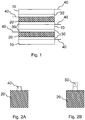
- a stacked battery is shown.
- an anode 10 and a cathode 20 are alternately arranged in the battery, wherein a separator 30 is arranged in each case between the anode 10 and the cathode 20 in order to spatially and electrically separate the two electrodes.
- the separator 30 must be permeable to ions that cause the conversion of stored chemical energy into electrical energy.
- 30 microporous plastics or nonwovens made of glass fiber or polyethylene are used for separators.
- the anodes 10 are connected to each other in their Ableiter Schemeen 40 as well as the cathodes 20, so that all identically named electrodes are connected together in a battery.
- the arrester regions 40 is in each case a terminal lug 50 (see Fig. 2B ) for the cathodes 20 and the anodes 10, which is connected to a corresponding external voltage pole of the battery.
- Fig. 2A shows a plan view of a cathode 20 with a discharge region 40.
- the cathode 20 are connected together.
- the terminal lug 50 is attached to the interconnected Ableiter Schemeen 40 which is in contact after the assembly of the battery to the negative pole of the battery.
- battery electrodes are prefabricated as a bulk or roll material, from which a desired electrode shape is cut out in the manufacture of a battery.
- the electrode material includes a collector substrate 60 provided with a coating film 70.
- the electrode material on one or more uncoated Ableiter Schemee 40, which are later required in the assembled state to dissipate voltage or current to the outside.
- the Ableiter Schemeen 40 several identically named electrodes are connected together and a metallic terminal lug 50 attached. Therefore, when the collector substrate 60 is coated on both sides, lead-out regions 40 are also formed on both sides.
- the Ableiter Symposiume not necessarily be formed opposite, but may be offset from each other, as in Fig. 3 shown.
- FIGS. 4A and 4B For example, methods of making an electrode material using a slot die system 300 are shown.
- an ink-type coating film 70 is applied on the belt-shaped collector substrate 60. This can be done either by discontinuous, intermittent coating, as in Fig. 4A shown by regular interruption of the coating, an uncoated arrester region 40 is formed, or by continuous coating, as in Fig. 4B shown.
- the formation of more complex Ableiter Schemeen with these methods is very complex. Therefore, occasional masking steps are used.
- arrester regions 40 may be exposed by brushing or similar methods on a collector substrate 60.
- the electrode material is calendered to densify the coating film and remove voids formed upon drying of the coating film 70.
- the finished electrode material can then be rolled up and stored until further processing.
- For making a battery is made of the electrode material cut or punched out a desired shape, which varies depending on the battery type or battery shape. When cutting out the battery electrode is also to be noted that a trap area 40 must be present. An example of a rectangular electrode shape with arrester region 40 is shown in FIG Fig. 2A shown.
- FIG. 3 is a flow chart illustrating the manufacturing process of a battery such as a winding cell or a stacked battery.
- the collector substrate 60 is coated with the coating film 70, for example, in an intermittent process (S10), and a plurality of uncoated arrester regions 40 are formed by interrupting or exposing to the application of the ink-type coating.
- the electrode material is calendered (S20).
- a desired electrode shape can then be cut out or punched out of the electrode material (S30), wherein the punched-out form must have a discharge region 40.
- the cut-out electrodes are stacked (S40) so as to alternately follow an anode 10 and a cathode 20 with a separator 30 therebetween (see Fig. 1 ).
- the arrester regions 40 of the cathodes 20 and the arrester regions 40 of the anodes 10 are each arranged one above the other and connected to one another.
- a terminal lug 50 is attached thereto (S50).
- the number of stacked anodes 10 and cathodes 20 may vary depending on the nature and characteristics of the battery.
- the electrode assembly is inserted into a housing and the terminal lugs 50 are connected to the outer voltage poles of the housing (S60). In a winding cell, the electrode assembly is further wound spirally and so inserted into the housing. After filling the electrolyte (S70), the cell is then closed (S80) and finally formed (S90).
- the lead-out area 40 is protruded from a coated electrode area to fix the terminal lug 50 thereon and connect electrodes of the same name.
- the size of the battery is unnecessarily increased or set an external shape of the battery.
- the arrester regions 40 can be easily contaminated in the conventional manufacturing processes or even during storage.
- contaminants can reach the arrester areas 40. This deteriorates the quality of an electrical contact between electrodes of the same name and between the electrodes and an associated terminal lug 50.
- the conductor regions 40 are formed prior to the calendering process during manufacture of the electrode material, calendering is made more difficult due to the irregularly thick structure.
- the arrester region 40 formed by conventional methods may be poorly defined, and more particularly, an edge portion of the arrestor region 40 may be made inaccurate and uneven.
- EP 1 596 459 A1 describes an electrochemical device and a method of manufacture. A plastic substrate is coated on both sides with a metal, which is then removed.
- EP 0 825 659 A2 describes an electrode for a secondary battery with a non-aqueous electrolyte and a method of preparation.
- an active material is applied, which is dried to form an active layer.
- Predetermined areas of the active material are then impregnated with a liquid, after curing of the liquid within the active material, the impregnated area is withdrawn to expose a surface of the collector.
- JP 2000 243376 A describes a battery electrode having on one side Ableiter Schemee in which Ableiterfahen are attached.
- JP 2001 043848 describes a method of manufacturing a polymer battery in which a porous coating film is removed from a current collector by adhering the coating film to a plurality of predetermined areas by means of a die, the bonded areas then being torn out of the coated area, respectively, to form drainage areas.
- the invention is based on the idea of arranging an uncoated region functioning as a conductor region on a collector substrate of a battery electrode in such a way that it protrudes into a coated region of the collector substrate or is arranged within the coated region.
- a total circumferential length of the coated portion is larger than that of a lead-out battery electrode.
- an outboard edge of the uncoated area ie an edge adjacent to an edge of the battery electrode, is minimized. In this way, an unused space in a battery caused by a lead-out area protruding from the battery electrode can be avoided, and an energy density can be increased with a constant battery volume.
- a battery electrode comprising a collector substrate, a coating film formed on the collector substrate, and a drain region, the drain region being largely surrounded by the coating film.
- the arrester region may have a peripheral region which coincides with an outer edge of the battery electrode, but the arrester region is predominantly adjacent to the active region of the battery electrode covered by the coating film, i. the arrester region is surrounded by the coating film at least in its half outer circumference.
- the arrester region can also lie completely in the coated region of the collector substrate, so that the arrester region adjoins the coating film over its entire circumference. In this way, an inactive area or dead volume can be reduced during assembly of the battery, so that a capacity and a volumetric energy density is increased for the same battery size.
- the drain region on the battery electrode is formed in any shape, for example, substantially circular, annular, rectangular, or triangular.
- the drain region may be disposed in a corner of the battery electrode so that two sides of the drain region are adjacent to the coating film.
- the arrester region can adjoin only one side of the outer edge of the battery electrode, so that three sides of the Ableiter Schemes are surrounded by the coated region of the battery electrode.
- the coating film is formed on both sides of the collector substrate to increase an active area of the battery electrode.
- at least one Ableiter Scheme be formed on both sides of the collector substrate.
- arrester regions are formed on both sides of the collector substrate, two arrester regions are preferably located opposite each other, so that battery electrodes of the same name can easily be connected to one another at the arrester region, for example by a welding contact.
- the Ableiter Schemee can be arranged offset from each other on both sides of the collector substrate.
- the trap region is made by laser ablation of the coating film so that the underlying collector substrate is exposed.
- the coating film can be produced over a large area or essentially completely and continuously on the collector substrate without having to omit a discharge region.
- the coating film may be formed on one or both sides of the collector substrate over a large area, so that the coated substrate has a uniform thickness.
- a calendering process is simplified and can be performed with better quality.
- the formation of the Ableiter Schemes then take place immediately before contacting the Ableiterrios, so that a fresh and clean surface for contacting is available.
- the arrester regions can be fabricated in any shape and location with clean and uniform edges on the coated collector substrate. This provides absolute freedom of design and the ability to produce surface-optimized arrester structures.
- the external shape of the battery electrode can also be cut out with a laser. This saves another tool or a further step and in particular expensive punching. This makes it possible to inexpensively produce any electrode shapes even at low quantities. Thus, with a single laser two different steps can be carried out with considerable time savings, thereby eliminating the need to react the electrode material or the tool to be processed.
- At least one recess may be formed in the battery electrode.
- the recess of an electrode corresponds to an arrester region formed on an electrode of the same name, so that the arrester regions of the eponymous electrodes arranged one above the other can be connected to one another through the other electrodes in the case of an alternating electrode arrangement.
- This may be advantageous, for example, if the arrester region of an electrode protrudes into or is completely surrounded by a coated electrode region.
- the cutting of the at least one recess can also be done with the help of the laser to optimize a procedure.
- any suitable laser system may be used, e.g. Cutting or engraving laser systems. Due to the high edge quality and cutting precision with regard to cutting and penetration depth, high-quality discharge areas can be produced. In addition, the use of ultrashort laser pulses can reduce the energy input, so that a thermal load on the electrode material is kept low. Since suitable laser systems are comparably expensive as slot nozzle systems, there are no high initial costs.
- a battery which includes at least one battery electrode according to one of the above embodiments. Since the battery electrode can be made more compact by forming a trap region, which is predominantly surrounded by a coating film, and thus has a smaller footprint, a volumetric energy density of the battery can be increased.
- a method of manufacturing a battery electrode wherein a coating film is deposited on a collector substrate. In a discharge region, the coating film is then removed so that a circumference of the discharge region is predominantly or at least half surrounded by the coating film. Since the arrester region is formed by ablation of the coating film, the substantially completely coated collector substrate can be stored as an electrode material without special precautions and the formation of the arrester region only take place immediately before contacting the arrester region. In this way impurities and chemical changes of the surface are avoided and a contact resistance in the arrester region is reduced. Furthermore, in this method, the coating film can be formed on an entire surface of the collector substrate over a large area and / or almost completely.
- the coating film also becomes on both sides of the collector substrate educated.
- continuous coating technologies such as doctor blade, comma-bar and kiss-coating are used, so that the manufacturing costs can be reduced.
- the coated collector substrate has a uniform thickness, thereby simplifying and improving a calendering process.
- the coating film is removed in the arrester region with a laser.
- a thin layer of the collector substrate can simultaneously be removed in the arrester region in order to improve a surface condition in the arrester area.
- the present invention will be described with reference to the example of the lithium-ion battery, which is characterized by a high energy density and thermal stability.
- the present invention is not intended to be limited to lithium-ion batteries, but can be applied to any battery.
- a collector substrate 60 is an anode 10 made of, for example, copper coated with a coating film 70 of graphite, binder, carbon black, and solvent. According to the present invention, the coating film 70 is removed in a trap region 40 so that the collector substrate 60 in the trap region 40 is exposed.
- a terminal lug 50 for example, be fastened from nickel.
- a collector substrate 60 is made of aluminum, for example, and is coated with a coating film 70 of an active material, binder, carbon black, graphite, and solvent contributing to a redox reaction.
- the terminal lug of the cathode is preferably also made of aluminum.
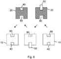
- Fig. 6 battery electrodes according to the present invention are shown in which a trap region 40 is circumferentially predominantly abutted against the coating film 70 on the collector substrate 60.
- Both the anodes 10 and the cathodes have an internal arrester area 40 and a recess 80.
- the recess 80 is formed at a position corresponding to the lead-out portion 40 of the respective opposed electrode in the assembled state.
- the recesses 80 of the anodes 10 are thus arranged so that they lie in the assembled state of the electrodes above or below the arrester regions 40 of the cathodes 10.
- the arrows in Fig. 6 indicate an electrode assembly in the assembled state, wherein alternately an anode 10 and a cathode 20 are arranged one above the other.
- a separator 30 is disposed between the anodes 10 and cathodes 20 (not shown), which may consist of microporous films or nonwoven fabrics.
- the terminal lugs 50 are preferably fastened to the arrester regions 40 after assembly of the electrodes, for example by ultrasonic welding. Since, in this exemplary embodiment, an arrester region 40 of an electrode faces a recess 80 of a counterpart electrode, the anodes 10 and cathodes 20 can be electrically connected to one another at their arrester regions 40 at the same time.
- FIG. 7 Another embodiment of battery electrodes according to the present invention is shown.
- anodes 10 shown have a circular recess 80 in its center, while the cathodes 20 in their middle have a corresponding arrester area 40.
- the arrester region 40 of the anodes 10 is formed at its peripheral edge, so that the cathodes 20 have a recess 80 at this point.
- the arrester regions 40 of the electrodes of the same name are connected to one another and terminal lugs 50 are respectively fixed in the arrester regions 40 of the anodes 10 and the cathodes 20.
- FIG. 8 Another example of battery electrodes according to the present invention is shown.
- the arrester regions 40 are completely surrounded by the coating film 70.
- the anode 10 has two arrester regions 40a and 40b and the cathode 20 has two corresponding recesses 80a and 80b.
- a connection lug 50 is attached to each of the two arrester regions 40a and 40b of the anode 10. Forming multiple drain regions 40 on an electrode can result in improved voltage dissipation and reduce resistance.
- a collector substrate 60 is coated over a large area and coated on both sides with a coating film 70.
- the collector substrate 60 may also be coated on only one surface over a large area or substantially completely.
- the coating film 70 is applied to the collector substrate 60 in a liquid state.
- simple, continuous coating technologies such as doctor blade, comma-bar or kiss coating can be used.
- the coating film 70 is dried or cured, wherein a thickness of the coating film 70 in the dry state is, for example, about 25 ⁇ m.
- the coated collector substrate 60 After drying or curing of the coating film 70, the coated collector substrate 60 is calendered to densify the coating film 70. Due to the uniform thickness of the collector substrate 60, the calendering process is simplified and can be performed more efficiently, so that the quality of the electrode material is improved. In addition, the coated collector substrate 60 can be stored as a roll material and is available as electrode material for subsequent further processing.
- At least one arrester region 40 is subsequently formed on the coated collector substrate 60 by removing the coating film 70 in the arrester region 40 by laser ablation and exposing the underlying collector substrate 60.
- the trap region 40 may also be fabricated by brushing, lithography, and other methods.
- a laser ablation material is removed from the surface by bombardment with laser radiation.
- laser radiation for this purpose, for example, pulsed laser radiation with high power density is used. Since the heat conduction allows only a very slow energy transport into the volume, the radiated energy is concentrated on a very thin layer at the surface. As a result, the surface is strongly heated and it comes to the sudden evaporation or melting of the material.
- a wavelength of the laser radiation is selected as a function of the material to be ablated.
- an engraving or cutting laser system is used, for example with an Ytterbium fiber laser at a wavelength of 1070 nm.
- other gas, solid state or fiber lasers can be used.
- a process gas or blowing gas may also be directed to the surface to drive the removed material out of the kerf or to prevent undesirable surface chemical reactions.
- the arrester regions 40 are fabricated by laser ablation, any arrester region shapes and arrangements can be formed.
- the arrester regions 40 can be arranged on the electrode surface such that they do not protrude from the battery electrode. Thereby, an energy density / volume ratio can be increased and the size of a battery can be reduced with the same electrical characteristics.
- the formation of the arrester region 40 preferably takes place immediately before the connection of electrodes of the same name or the attachment of a terminal lug 50 in the arrester regions 40.
- superimposed electrodes of the same name can be connected to one another by a welding contact in the arrester regions 40.
- a connection lug 50 can be fastened to one of the arrester regions 40 at the same time.
- the arrester regions 40 are formed shortly before the further processing of the electrode material, a fresh, clean surface is available for contacting the electrodes of the same name or for attaching the terminal lug 50.
- passivation layers such as, for example, oxidized surfaces and other impurities in the arrester area 40 can be avoided.
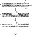
- the coating film 70 in the lead-out region 40 may be removed by laser, but as in FIG Fig. 9C also, a thin layer of the collector substrate 60.
- the penetration depth of the laser can be controlled exactly, so that the depth of material removal can be chosen arbitrarily. Therefore, a collector substrate 60 can be selectively thinned in the arrester region 40. In addition, this can improve the surface finish for electrical contacting.
- FIG. 10 is a flowchart of a manufacturing process of a battery according to the present invention.
- a collector substrate 60 composed of an approximately 8-20 ⁇ m-thick metal tape
- an ink-type coating film 70 is applied over a large area or almost completely (S100).
- the uniformly coated collector substrate 60 is calendered (S200) to remove voids and irregularities resulting from drying from the coating film 70.
- the calendered and coated collector substrate 60 can now be stored as roll material until further processing.
- the coating film 70 in a predetermined drain region 40 on the coated collector substrate 60 is removed by laser ablation (S300).
- a thin layer of the collector substrate 60 may be additionally removed in the arrester area 40 in order to improve a surface quality for electrical contacting.
- the electrode and optionally the recesses 80 are then cut out of the coated collector substrate 60 in a desired shape.
- the electrode or the recess 80 is cut out with a laser, but alternatively, a punching device can be used.
- the order of steps S400 and S300 can also be reversed. Thereafter, anodes 10 and cathodes 20 are alternately arranged one above the other so that each of the Ableiter Schemee 40 lie opposite electrodes of the same, between the Ableiter Schemeen 40 of the anodes 10, the recesses 80 of the cathode 20 and vice versa are arranged.
- each of the Ableiter Schemee 40 are connected by the same name electrodes, for example, by ultrasonic welding, each with a terminal lug 50 is attached thereto (S500).
- the terminal lug 50 may be attached to one of the cathodes 20 and anodes 10 prior to assembling the electrodes.
- the other steps are the same as those of the conventional method of manufacturing a battery.
- the electrode assembly is inserted into a container and the terminal lugs 50 are connected to the external voltage poles of the battery (S60).
- an electrolyte is filled in (S70) and the cell is sealed (S80).
- a formation (S90) is performed.
- the arrester regions may be formed so as not to protrude from an outer periphery of the battery electrode but protrude into a coated region of the battery electrode. As a result, a higher capacity and energy density can be achieved with the same battery size.
Description
Die Erfindung betrifft eine Batterieelektrode und ein Verfahren zum Herstellen derselben.The invention relates to a battery electrode and a method for producing the same.
Im Allgemeinen bezeichnet eine Batterie sowohl nicht-wiederaufladbare Primärzellen als auch wiederaufladbare Sekundärzellen (auch Akku genannt). Batterien werden anhand der zugrundeliegenden chemischen Redoxreaktion, der eingesetzten Materialien, der elektrischen Werte (z.B. Spannung oder Kapazität) oder der geometrischen oder konstruktiven Bauform eingeteilt. Beispielsweise gibt es Alkali-Mangan-Batterien, Zink-Kohle-Batterien oder Lithiumbatterien. Entsprechend ihrem inneren Aufbau werden bei Batterien des Weiteren Wickelzellen und Stapelbatterien unterschieden. Bei einer Wickelzelle werden die übereinander angeordneten Elektroden- und Separatorschichten spiralförmig aufgewickelt und beispielsweise in eine Rundbatterie mit zylindrischem Gehäuse eingebaut. Bei einer Stapelbatterie hingegen werden mehrere Elektroden- und Separatorschichten abwechselnd übereinander gestapelt.In general, a battery refers to both non-rechargeable primary cells and rechargeable secondary cells (also called battery). Batteries are classified based on the underlying chemical redox reaction, the materials used, the electrical values (e.g., voltage or capacitance), or the geometric or structural design. For example, there are alkaline manganese batteries, zinc-carbon batteries or lithium batteries. According to their internal construction, batteries and winding batteries are further differentiated in batteries. In a winding cell, the stacked electrode and separator layers are spirally wound and installed, for example, in a round battery with a cylindrical housing. In a stacked battery, however, several electrode and separator layers are alternately stacked.
In
Üblicherweise werden Batterieelektroden als Bulk- oder Rollenmaterial vorgefertigt, aus dem bei der Herstellung einer Batterie eine gewünschte Elektrodenform ausgeschnitten wird. Wie in
In
Nach der Beschichtung wird das Elektrodenmaterial kalandriert, um den Beschichtungsfilm zu verdichten und Hohlräume zu beseitigen, die beim Trocknen des Beschichtungsfilms 70 entstehen. Das fertige Elektrodenmaterial kann dann aufgerollt und bis zur Weiterverarbeitung gelagert werden. Für das Herstellen einer Batterie wird aus dem Elektrodenmaterial eine gewünschte Form ausgeschnitten oder ausgestanzt, die je nach Batterietyp oder Batterieform unterschiedlich ist. Beim Ausschneiden der Batterieelektrode ist zudem zu beachten, dass ein Ableiterbereich 40 vorhanden sein muss. Ein Beispiel für eine rechteckige Elektrodenform mit Ableiterbereich 40 ist in
In
Bei den herkömmlichen Verfahren zum Herstellen von Batterieelektroden bestehen allerdings folgende Probleme. So ist das Herstellen von unbeschichteten Ableiterbereichen durch Maskierungsschritte oder Abbürsten der Beschichtung sehr aufwändig und teuer. Bei dem alternativen Herstellungsverfahren durch intermittierende oder kontinuierliche Beschichtung mit Hilfe eines Schlitzdüsensystems hingegen sind die möglichen Formen und Anordnungen der Ableiterbereiche auf dem Elektrodenmaterial stark eingeschränkt. Angesichts der vielfältigen Einsatzgebiete von Batterien insbesondere in Design-Produkten wie beispielsweise in Mobiltelefonen, Laptops oder Autos wird allerdings eine Flexibilität bei der Gestaltung der Batterieelektroden immer stärker gefordert. Hierbei stellt der Trend zu kleineren Geräten eine besondere Herausforderung an die Batterieherstellung dar. Zum einen müssen daher Batterien mit kleineren Abmessungen entwickelt werden, zum anderen sind häufig komplexe Formen gefordert, um den Innenraum eines Geräts möglichst effizient zu nutzen. Darüber hinaus ist es bei einem intermittierenden Beschichtungsverfahren schwierig, regelmäßige und saubere Randbereiche zwischen Beschichtungsbereich und Ableiterbereich herzustellen.However, the following problems exist in the conventional methods of manufacturing battery electrodes. Thus, the production of uncoated Ableiterbereichen by masking or brushing the coating is very complex and expensive. In the alternative manufacturing method by intermittent or continuous coating by means of a slot nozzle system, however, the possible shapes and arrangements of the Ableiterbereiche on the electrode material are severely limited. in view of However, the flexible use of batteries, especially in design products such as mobile phones, laptops or cars, requires more and more flexibility in the design of the battery electrodes. The trend towards smaller devices represents a particular challenge for battery production. On the one hand, therefore, batteries with smaller dimensions have to be developed, on the other hand, complex shapes are often required in order to use the interior of a device as efficiently as possible. Moreover, in an intermittent coating process, it is difficult to produce regular and clean edge areas between the coating area and the arrester area.
Darüber hinaus ist es mit den herkömmlichen Verfahren schwierig und teuer, eine Formenvielfalt der Elektroden zu realisieren. Aus Kostengründen wird üblicherweise ein Rollenmaterial als Elektrodenmaterial verwendet, bei dem mögliche Positionen des unbeschichteten Ableiterbereichs 40 bezüglich des Beschichtungsfilms 70 fest definiert sind. Dadurch ist allerdings die Designfreiheit für die Elektrodenform stark eingeschränkt, weil jede Elektrode einen Ableiterbereich 40 aufweisen muss. Außerdem entsteht beim Ausschneiden der gewünschten Elektrodenform mitsamt des Ableiterbereichs 40 viel überschüssiges Elektrodenmaterial, das verworfen werden muss. Wenn beispielsweise kleine Elektroden so ausgeschnitten werden, dass sie einen Ableiterbereich 40 enthalten, können bei einem großen Abstand zwischen aufeinanderfolgenden Ableiterbereichen 40 Bereiche des dazwischen liegenden beschichteten Substrats nicht mehr verwendet werden. Dadurch wird der Materialverbrauch erhöht und das Herstellungsverfahren verteuert. Des Weiteren muss für jede gewünschte Elektrodenform eine eigene Stanzform zum Ausstanzen der gewünschten Form angeschafft werden. Aufgrund der hohen Anforderungen an eine Schneidgüte sind diese Stanzformen jedoch sehr teuer.Moreover, with the conventional methods, it is difficult and expensive to realize a variety of shapes of the electrodes. For cost reasons, usually a roll material is used as the electrode material, in which possible positions of the
In den herkömmlichen Herstellungsverfahren wird der Ableiterbereich 40 von einem beschichteten Elektrodenbereich vorstehend ausgebildet, um daran die Anschlussfahne 50 zu befestigen und gleichnamige Elektroden miteinander zu verbinden. Dies führt jedoch zu ungenutztem Raum in der Batterie, der nicht durch aktives Elektrodenmaterial gefüllt ist. Dadurch wird die Größe der Batterie unnötig erhöht bzw. eine äußere Form der Batterie festgelegt.In the conventional manufacturing methods, the lead-
Des Weiteren können die Ableiterbereiche 40 in den herkömmlichen Herstellungsverfahren oder auch während des Lagems leicht verunreinigt werden. Insbesondere bei einem Kalandrierprozess können Verunreinigungen auf die Ableiterbereiche 40 gelangen. Dies verschlechtert die Qualität eines elektrischen Kontakts zwischen gleichnamigen Elektroden untereinander und zwischen den Elektroden und einer dazugehörigen Anschlussfahne 50. Da beim Herstellen des Elektrodenmaterials zudem die Ableiterbereiche 40 vor dem Kalandrierprozess ausgebildet werden, ist das Kalandrieren aufgrund der ungleichmäßig dicken Struktur erschwert. Außerdem kann der durch herkömmliche Verfahren ausgebildete Ableiterbereich 40 schlecht definiert sein, wobei besonders ein Randbereich des Ableiterbereichs 40 ungenau und ungleichmäßig ausgebildet sein kann.Furthermore, the
Daher ist es Aufgabe der vorliegenden Erfindung, eine Batterieelektrode und ein Herstellungsverfahren für selbige anzugeben, wobei eine volumetrische Energiedichte einer Batterie durch kompakte Gestaltung der Batterieelektrode bei geringen Herstellungskosten erhöht werden kann.Therefore, it is an object of the present invention to provide a battery electrode and a manufacturing method for the same, wherein a volumetric energy density of a battery can be increased by compact design of the battery electrode at a low manufacturing cost.
Die Aufgabe wird durch die Merkmale der unabhängigen Ansprüche gelöst.The object is solved by the features of the independent claims.
Die Erfindung basiert auf dem Gedanken, einen als Ableiterbereich fungierenden unbeschichteten Bereich auf einem Kollektorsubstrat einer Batterieelektrode so anzuordnen, dass er in einen beschichteten Bereich des Kollektorsubstrats hineinragt oder innerhalb des beschichteten Bereichs angeordnet ist. Wenn der unbeschichtete Ableiterbereich in den beschichteten Bereich hineinragt, ist eine gesamte Umfangslänge des beschichteten Bereichs größer als bei einer Batterieelektroden mit vorstehendem Ableiterbereich. Zugleich ist ein außen liegender Rand des unbeschichteten Bereichs, d.h. ein an eine Kante der Batterieelektrode angrenzender Rand, minimiert. Auf diese Weise kann ein ungenützter Raum in einer Batterie, der durch einen von der Batterieelektrode vorstehenden Ableiterbereich verursacht wird, vermieden und eine Energiedichte bei gleichbleibendem Batterievolumen erhöht werden.The invention is based on the idea of arranging an uncoated region functioning as a conductor region on a collector substrate of a battery electrode in such a way that it protrudes into a coated region of the collector substrate or is arranged within the coated region. When the uncoated lead portion protrudes into the coated portion, a total circumferential length of the coated portion is larger than that of a lead-out battery electrode. At the same time, an outboard edge of the uncoated area, ie an edge adjacent to an edge of the battery electrode, is minimized. In this way, an unused space in a battery caused by a lead-out area protruding from the battery electrode can be avoided, and an energy density can be increased with a constant battery volume.
Gemäß einem Aspekt der vorliegenden Erfindung wird eine Batterieelektrode angegeben, die ein Kollektorsubstrat, einen auf dem Kollektorsubstrat ausgebildeten Beschichtungsfilm und einen Ableiterbereich umfasst, wobei der Ableiterbereich zu einem Großteil vom Beschichtungsfilm umgeben ist. Der Ableiterbereich kann einen Umfangsbereich aufweisen, der mit einem äußeren Rand der Batterieelektrode zusammenfällt, wobei der Ableiterbereich allerdings überwiegend an den aktiven vom Beschichtungsfilm bedeckten Bereich der Batterieelektrode angrenzt, d.h. der Ableiterbereich ist wenigstens in seinem halben Außenumfang vom Beschichtungsfilm umgeben. Alternativ kann der Ableiterbereich jedoch auch vollständig im beschichteten Bereich des Kollektorsubstrats liegen, sodass der Ableiterbereich an seinem gesamten Umfang an den Beschichtungsfilm angrenzt. Auf diese Weise kann beim Zusammensetzen der Batterie ein inaktiver Bereich bzw. Totvolumen reduziert werden, sodass bei gleicher Batteriegröße eine Kapazität und eine volumetrische Energiedichte erhöht wird.According to one aspect of the present invention, there is provided a battery electrode comprising a collector substrate, a coating film formed on the collector substrate, and a drain region, the drain region being largely surrounded by the coating film. The arrester region may have a peripheral region which coincides with an outer edge of the battery electrode, but the arrester region is predominantly adjacent to the active region of the battery electrode covered by the coating film, i. the arrester region is surrounded by the coating film at least in its half outer circumference. Alternatively, however, the arrester region can also lie completely in the coated region of the collector substrate, so that the arrester region adjoins the coating film over its entire circumference. In this way, an inactive area or dead volume can be reduced during assembly of the battery, so that a capacity and a volumetric energy density is increased for the same battery size.
In einem Ausführungsbeispiel ist der Ableiterbereich auf der Batterieelektrode in einer beliebigen Form ausgebildet, beispielsweise im Wesentlichen kreisförmig, ringförmig, rechteckig oder dreieckig. Wenn sowohl der Ableiterbereich als auch die Batterieelektrode eine rechteckige Form aufweisen, kann der Ableiterbereich in einer Ecke der Batterieelektrode angeordnet sein, so dass zwei Seiten des Ableiterbereichs an den Beschichtungsfilm angrenzen. Alternativ kann der Ableiterbereich nur mit einer Seite an den äußeren Rand der Batterieelektrode angrenzen, so dass drei Seiten des Ableiterbereichs von dem beschichteten Bereich der Batterieelektrode umgeben sind.In one embodiment, the drain region on the battery electrode is formed in any shape, for example, substantially circular, annular, rectangular, or triangular. When both the drain region and the battery electrode have a rectangular shape, the drain region may be disposed in a corner of the battery electrode so that two sides of the drain region are adjacent to the coating film. Alternatively, the arrester region can adjoin only one side of the outer edge of the battery electrode, so that three sides of the Ableiterbereichs are surrounded by the coated region of the battery electrode.
Vorzugsweise ist der Beschichtungsfilm auf beiden Seiten des Kollektorsubstrats ausgebildet, um eine aktive Fläche der Batterieelektrode zu erhöhen. In diesem Fall kann jeweils mindestens ein Ableiterbereich auf beiden Seiten des Kollektorsubstrats ausgebildet sein. Wenn Ableiterbereiche auf beiden Seiten des Kollektorsubstrats ausgebildet sind, liegen sich jeweils zwei Ableiterbereiche vorzugsweise gegenüber, so dass gleichnamige Batterieelektroden am Ableiterbereich beispielsweise durch einen Schweißkontakt leicht miteinander verbunden werden können. Alternativ können die Ableiterbereiche gegeneinander versetzt auf beiden Seiten des Kollektorsubstrats angeordnet sein.Preferably, the coating film is formed on both sides of the collector substrate to increase an active area of the battery electrode. In this case, in each case at least one Ableiterbereich be formed on both sides of the collector substrate. If arrester regions are formed on both sides of the collector substrate, two arrester regions are preferably located opposite each other, so that battery electrodes of the same name can easily be connected to one another at the arrester region, for example by a welding contact. Alternatively, the Ableiterbereiche can be arranged offset from each other on both sides of the collector substrate.
In einem bevorzugten Ausführungsbeispiel wird der Ableiterbereich durch Laserablation des Beschichtungsfilms hergestellt, sodass das darunterliegende Kollektorsubstrat freigelegt wird. Auf diese Weise kann der Beschichtungsfilm großflächig oder im Wesentlichen vollständig und kontinuierlich auf dem Kollektorsubstrat hergestellt werden, ohne einen Ableiterbereich aussparen zu müssen. Zudem kann der Beschichtungsfilm auf einer oder auf beiden Seiten des Kollektorsubstrats großflächig ausgebildet sein, so dass das beschichtete Substrat eine gleichmäßige Dicke aufweist. Wegen der gleichmäßigen Dicke des beschichteten Kollektorsubstrats ist darüber hinaus ein Kalandrierprozess vereinfacht und kann mit besserer Qualität durchgeführt werden. Darüber hinaus kann das Ausbilden des Ableiterbereichs dann unmittelbar vor Kontaktieren des Ableiterbereichs erfolgen, so dass eine frische und saubere Oberfläche für die Kontaktierung zur Verfügung steht. Daher kann das Auftreten von Verunreinigungen vermieden werden, die eine ernsthafte Gefahr für eine fertige Batterie darstellen und Dendritenbildung mit daraus resultierendem Kurzschluss verursachen können, wie beispielsweise beim Bürsten entstehende Schleifpartikel oder Beschichtungsreste. Durch die Verwendung eines Lasers zum Freilegen der Ableiterbereiche können die Ableiterbereiche außerdem in beliebiger Form und an jeder beliebigen Stelle mit sauberen und gleichmäßigen Kanten auf dem beschichteten Kollektorsubstrat hergestellt werden. Dadurch besteht absolute Designfreiheit und die Möglichkeit, flächenoptimierte Ableiterstrukturen herzustellen. Die äußere Form der Batterieelektrode kann ebenfalls mit einem Laser ausgeschnitten werden. Dies erspart ein weiteres Werkzeug bzw. einen weiteren Arbeitsschritt und insbesondere teure Stanzformen. Dadurch wird es möglich, beliebige Elektrodenformen schon bei geringen Stückzahlen kostengünstig herzustellen. Somit können mit einem einzigen Laser zwei verschiedene Arbeitsschritte mit erheblicher Zeitersparnis durchgeführt werden, wodurch auch ein Umsetzen des zu bearbeitenden Elektrodenmaterials oder des Werkzeugs entfällt.In a preferred embodiment, the trap region is made by laser ablation of the coating film so that the underlying collector substrate is exposed. In this way, the coating film can be produced over a large area or essentially completely and continuously on the collector substrate without having to omit a discharge region. In addition, the coating film may be formed on one or both sides of the collector substrate over a large area, so that the coated substrate has a uniform thickness. Moreover, because of the uniform thickness of the coated collector substrate, a calendering process is simplified and can be performed with better quality. In addition, the formation of the Ableiterbereichs then take place immediately before contacting the Ableiterbereichs, so that a fresh and clean surface for contacting is available. Therefore, the occurrence of impurities that pose a serious danger to a finished battery and can cause dendrite formation with resulting short circuit such as abrasive particles or coating residues resulting from brushing can be avoided. In addition, by using a laser to expose the arrester regions, the arrester regions can be fabricated in any shape and location with clean and uniform edges on the coated collector substrate. This provides absolute freedom of design and the ability to produce surface-optimized arrester structures. The external shape of the battery electrode can also be cut out with a laser. This saves another tool or a further step and in particular expensive punching. This makes it possible to inexpensively produce any electrode shapes even at low quantities. Thus, with a single laser two different steps can be carried out with considerable time savings, thereby eliminating the need to react the electrode material or the tool to be processed.
Des Weiteren kann mindestens eine Aussparung in der Batterieelektrode ausgebildet sein. Vorzugsweise entspricht die Aussparung einer Elektrode einem auf einer gegennamigen Elektrode ausgebildeten Ableiterbereich, damit die übereinander angeordneten Ableiterbereiche der gleichnamigen Elektroden bei einer alternierenden Elektrodenanordnung durch die anderen Elektroden hindurch miteinander verbunden werden können. Dies kann beispielsweise vorteilhaft sein, wenn der Ableiterbereich einer Elektrode in einen beschichteten Elektrodenbereich hineinragt oder von diesem vollständig umgeben ist. Wenn die Batterieelektrode mittels Laserschneiden ausgeschnitten wird, kann das Ausschneiden der mindestens einen Aussparung ebenfalls mit Hilfe des Lasers erfolgen, um einen Verfahrensablauf zu optimieren.Furthermore, at least one recess may be formed in the battery electrode. Preferably, the recess of an electrode corresponds to an arrester region formed on an electrode of the same name, so that the arrester regions of the eponymous electrodes arranged one above the other can be connected to one another through the other electrodes in the case of an alternating electrode arrangement. This may be advantageous, for example, if the arrester region of an electrode protrudes into or is completely surrounded by a coated electrode region. When the battery electrode is cut out by means of laser cutting, the cutting of the at least one recess can also be done with the help of the laser to optimize a procedure.
Für den Materialabtrag mittels Laserablation bzw. für das Laserschneiden kann jedes geeignete Lasersystem verwendet werden, z.B. Schneid- oder Gravurlasersysteme. Aufgrund der hohen Kantenqualität und Schnittpräzision bezüglich Schnittführung und Eindringtiefe können Ableiterbereiche von hoher Qualität hergestellt werden. Durch die Verwendung von ultrakurzen Laserpulsen kann darüber hinaus der Energieeintrag reduziert werden, sodass eine thermische Belastung des Elektrodenmaterials gering gehalten wird. Da geeignete Lasersysteme vergleichbar teuer wie Schlitzdüsensysteme sind, entstehen keine hohen Anschaffungskosten.For material removal by means of laser ablation or for laser cutting, any suitable laser system may be used, e.g. Cutting or engraving laser systems. Due to the high edge quality and cutting precision with regard to cutting and penetration depth, high-quality discharge areas can be produced. In addition, the use of ultrashort laser pulses can reduce the energy input, so that a thermal load on the electrode material is kept low. Since suitable laser systems are comparably expensive as slot nozzle systems, there are no high initial costs.
In einem weiteren Aspekt der vorliegenden Erfindung wird eine Batterie angegeben, die mindestens eine Batterieelektrode nach einem der obigen Ausführungsbeispiele enthält. Da die Batterieelektrode durch Ausbilden eines Ableiterbereichs, der überwiegend von einem Beschichtungsfilm umgeben ist, kompakter gestaltet werden kann und somit einen geringeren Platzbedarf aufweist, kann eine volumetrische Energiedichte der Batterie erhöht werden.In a further aspect of the present invention, a battery is disclosed which includes at least one battery electrode according to one of the above embodiments. Since the battery electrode can be made more compact by forming a trap region, which is predominantly surrounded by a coating film, and thus has a smaller footprint, a volumetric energy density of the battery can be increased.
In einem weiteren Aspekt der vorliegenden Erfindung wird ein Verfahren zum Herstellen einer Batterieelektrode angegeben, wobei auf einem Kollektorsubstrat ein Beschichtungsfilm aufgetragen wird. In einem Ableiterbereich wird anschließend der Beschichtungsfilm so entfernt, dass ein Umfang des Ableiterbereichs überwiegend bzw. wenigstens zur Hälfte vom Beschichtungsfilm umgeben ist. Da der Ableiterbereich durch Abtragen des Beschichtungsfilms ausgebildet wird, kann das im Wesentlichen vollständig beschichtete Kollektorsubstrat als Elektrodenmaterial ohne besondere Vorkehrungen gelagert werden und die Ausbildung des Ableiterbereichs erst unmittelbar vor einer Kontaktierung des Ableiterbereichs erfolgen. Auf diese Weise werden Verunreinigungen und chemische Veränderungen der Oberfläche vermieden und ein Kontaktwiderstand im Ableiterbereich reduziert. Des Weiteren kann bei diesem Verfahren der Beschichtungsfilm auf einer gesamten Oberfläche des Kollektorsubstrats großflächig und/oder nahezu vollständig ausgebildet werden. Möglicherweise wird der Beschichtungsfilm auch auf beiden Seiten des Kollektorsubstrats ausgebildet. Vorteilhafterweise werden kontinuierliche Beschichtungstechnologien, wie beispielsweise Doctor-blade, Comma-bar und Kiss-Coating verwendet, so dass die Herstellungskosten reduziert werden können. Darüber hinaus weist das beschichtete Kollektorsubstrat eine gleichmäßige Dicke auf, wodurch ein Kalandrierprozess vereinfacht und verbessert wird.In another aspect of the present invention, there is provided a method of manufacturing a battery electrode, wherein a coating film is deposited on a collector substrate. In a discharge region, the coating film is then removed so that a circumference of the discharge region is predominantly or at least half surrounded by the coating film. Since the arrester region is formed by ablation of the coating film, the substantially completely coated collector substrate can be stored as an electrode material without special precautions and the formation of the arrester region only take place immediately before contacting the arrester region. In this way impurities and chemical changes of the surface are avoided and a contact resistance in the arrester region is reduced. Furthermore, in this method, the coating film can be formed on an entire surface of the collector substrate over a large area and / or almost completely. Possibly, the coating film also becomes on both sides of the collector substrate educated. Advantageously, continuous coating technologies, such as doctor blade, comma-bar and kiss-coating are used, so that the manufacturing costs can be reduced. Moreover, the coated collector substrate has a uniform thickness, thereby simplifying and improving a calendering process.
In einem bevorzugten Ausführungsbeispiel wird der Beschichtungsfilm im Ableiterbereich mit einem Laser entfernt. Dabei kann in einem bevorzugten Ausführungsbeispiel gleichzeitig eine dünne Schicht des Kollektorsubstrats im Ableiterbereich abgetragen werden, um eine Oberflächenbeschaffenheit im Ableiterbereich zu verbessern. Durch Verwendung der Laserablation zum Ausbilden des Ableiterbereichs wird eine Designfreiheit in der Gestaltung der Batterieelektrode und des Ableiterbereichs erhöht und individuelle Anfertigungen ermöglicht.In a preferred embodiment, the coating film is removed in the arrester region with a laser. In this case, in a preferred exemplary embodiment, a thin layer of the collector substrate can simultaneously be removed in the arrester region in order to improve a surface condition in the arrester area. By using the laser ablation to form the trap region, design freedom in the design of the battery electrode and the trap region is increased and individual fabrication is enabled.
In den Figuren zeigen
-
Fig. 1 eine schematische Schnittansicht einer Elektrodenanordnung in einer herkömmlichen Batterie; -
Figuren 2A und 2B eine Draufsicht auf eine herkömmliche Batterieelektrode; -
Fig. 3 zeigt eine Schnittansicht eines herkömmlichen Elektrodenmaterials; -
Figuren 4A und 4B Verfahren zum Herstellen eines herkömmlichen Elektrodenmaterials; -
Fig. 5 ein Ablaufdiagramm eines herkömmlichen Herstellungsverfahrens einer Batterie; -
Fig. 6 Batterieelektroden gemäß einem ersten Ausführungsbeispiel der vorliegenden Erfindung; -
Fig. 7 Batterieelektroden gemäß einem weiteren Ausführungsbeispiel der vorliegenden Erfindung; -
Fig. 8 Batterieelektroden gemäß einem anderen Ausführungsbeispiel der vorliegenden Erfindung; -
Fig. 9A-9C Schnittansichten durch ein Elektrodenmaterial während eines Herstellungsprozesses gemäß der vorliegenden Erfindung; und -
Fig. 10 ein Ablaufdiagramm eines Herstellungsverfahrens gemäß einem Ausführungsbeispiel der vorliegenden Erfindung.
-
Fig. 1 a schematic sectional view of an electrode assembly in a conventional battery; -
FIGS. 2A and 2B a plan view of a conventional battery electrode; -
Fig. 3 shows a sectional view of a conventional electrode material; -
FIGS. 4A and 4B A method of manufacturing a conventional electrode material; -
Fig. 5 a flowchart of a conventional manufacturing method of a battery; -
Fig. 6 Battery electrodes according to a first embodiment of the present invention; -
Fig. 7 Battery electrodes according to another embodiment of the present invention; -
Fig. 8 Battery electrodes according to another embodiment of the present invention; -
Figs. 9A-9C Sectional views through an electrode material during a manufacturing process according to the present invention; and -
Fig. 10 a flowchart of a manufacturing method according to an embodiment of the present invention.
Im Folgenden wird die Erfindung anhand des Beispiels der Lithium-Ionen-Batterie beschrieben, die sich durch eine hohe Energiedichte und thermische Stabilität auszeichnet. Die vorliegende Erfindung soll jedoch nicht auf Lithium-Ionen-Batterien beschränkt sein, sondern kann auf jede beliebige Batterie angewendet werden.In the following, the invention will be described with reference to the example of the lithium-ion battery, which is characterized by a high energy density and thermal stability. However, the present invention is not intended to be limited to lithium-ion batteries, but can be applied to any battery.
Bei einer Lithium-Ionen-Batterie besteht ein Kollektorsubstrat 60 einer Anode 10 beispielsweise aus Kupfer, das mit einem Beschichtungsfilm 70 aus Graphit, Bindemittel, Ruß und Lösungsmittel beschichtet ist. Gemäß der vorliegenden Erfindung wird der Beschichtungsfilm 70 in einem Ableiterbereich 40 entfernt, sodass das Kollektorsubstrat 60 im Ableiterbereich 40 freigelegt ist. Am Ableiterbereich 40 der Anode 10 kann eine Anschlussfahne 50 bspw. aus Nickel befestigt werden. Bei der Kathode 20 besteht ein Kollektorsubstrat 60 beispielsweise aus Aluminium und ist mit einem Beschichtungsfilm 70 aus einem zu einer Redoxreaktion beitragenden Aktivmaterial, Bindemittel, Ruß, Graphit und Lösungsmittel beschichtet. Die Anschlussfahne der Kathode besteht vorzugsweise ebenfalls aus Aluminium.In a lithium-ion battery, a
In
Es ist auch möglich, nur die Kathoden oder nur die Anoden mit einem innen liegenden oder hineinragenden Ableiterbereich auszubilden, wobei die andere der zwei Elektroden nach dem herkömmlichen Verfahren mit vorstehendem Ableiterbereich hergestellt wird.It is also possible to form only the cathodes or only the anodes with an internal or projecting arrester region, the other of the two electrodes being produced by the conventional process with the preceding arrester region.
In
In
Im Folgenden wird ein beispielhaftes Verfahren zur Herstellung der Batterieelektroden erläutert. Gemäß der vorliegenden Erfindung wird zunächst, wie in
Wie in
Da die Ableiterbereiche 40 durch Laserablation hergestellt werden, können beliebige Ableiterbereichformen und -anordnungen ausgebildet werden. Insbesondere können die Ableiterbereiche 40 so auf der Elektrodenfläche angeordnet werden, dass sie nicht von der Batterieelektrode vorstehen. Dadurch kann ein Energiedichte/Volumen-Verhältnis erhöht und die Größe einer Batterie bei gleichen elektrischen Eigenschaften verringert werden. Das Ausbilden des Ableiterbereichs 40 erfolgt vorzugsweise unmittelbar vor dem Verbinden von gleichnamigen Elektroden oder dem Anbringen einer Anschlussfahne 50 in den Ableiterbereichen 40. Beispielsweise können übereinanderliegende gleichnamige Elektroden durch einen Schweißkontakt in den Ableiterbereichen 40 miteinander verbunden werden. Hierbei kann gleichzeitig eine Anschlussfahne 50 an einem der Ableiterbereiche 40 befestigt werden. Da die Ableiterbereiche 40 erst kurz vor der Weiterverarbeitung des Elektrodenmaterials ausgebildet werden, steht für die Kontaktierung der gleichnamigen Elektroden untereinander bzw. für das Anbringen der Anschlussfahne 50 eine frische saubere Oberfläche zur Verfügung. Dadurch können Passivierungsschichten wie beispielsweise oxidierte Oberflächen und andere Verunreinigungen im Ableiterbereich 40 vermieden werden.Since the
Möglicherweise wird nicht nur der Beschichtungsfilm 70 im Ableiterbereich 40 mittels Laser entfernt, sondern wie in
Die weiteren Schritte entsprechen denen des herkömmlichen Verfahrens zum Herstellen einer Batterie. Die Elektrodenanordnung wird in einen Behälter eingesetzt und die Anschlussfahnen 50 werden mit den äußeren Spannungspolen der Batterie verbunden (S60). Anschließend wird ein Elektrolyt eingefüllt (S70) und die Zelle verschlossen (S80). Abschließend wird eine Formierung (S90) durchgeführt.The other steps are the same as those of the conventional method of manufacturing a battery. The electrode assembly is inserted into a container and the terminal lugs 50 are connected to the external voltage poles of the battery (S60). Then, an electrolyte is filled in (S70) and the cell is sealed (S80). Finally, a formation (S90) is performed.
Gemäß der vorliegenden Erfindung können die Ableiterbereiche so ausgebildet werden, dass sie nicht von einem Außenumfang der Batterieelektrode vorstehen, sondern in einen beschichteten Bereich der Batterieelektrode hineinragen. Dadurch kann bei gleicher Batteriegröße eine höhere Kapazität und Energiedichte erreicht werden.According to the present invention, the arrester regions may be formed so as not to protrude from an outer periphery of the battery electrode but protrude into a coated region of the battery electrode. As a result, a higher capacity and energy density can be achieved with the same battery size.
Claims (12)
- Battery electrode, comprising:a collector substrate (60);a calendered coating film (70), which contains an active material, on the collector substrate (60); andat least one conductor region (40) on the collector substrate (60), in which the collector substrate is exposed and in which the coating film (70) is removed, wherein the at least one conductor region (40) protrudes into a coated region of the collector substrate (60) or is arranged within the coated region,a recessed area (80) of the coated collector substrate (60) at a point in the coated collector substrate (60) at which the coated collector substrate (60) is extracted, wherein the position of the recessed area (80) in the assembled condition corresponds to a conductor region (40) of an adjacent battery electrode with opposite potential.
- Battery electrode according to Claim 1, wherein at least one half of the circumference of the conductor region (40) adjoins the coating film (70).
- Battery electrode according to Claim 1 or 2, wherein the conductor region (40) has a rectangular, triangular, circular or annular shape or a section thereof.
- Battery electrode according to one of the preceding claims, wherein along its circumference the conductor region (40) is completely surrounded by the coating film (70).
- Battery electrode according to one of the preceding claims, wherein the coating film (70) and/or at least one conductor region (40) is formed on both sides of the collector substrate (60).
- Battery electrode according to one of the preceding claims, wherein the conductor region (40) is produced by laser ablation of the coating film (70).
- Battery electrode according to one of the preceding claims, wherein the battery electrode and/or the recessed area (80) is extracted by laser cutting.
- Battery containing at least one battery electrode according to one of the preceding claims.
- Method for producing a battery electrode, comprising:forming a calendered coating film (70), which contains an active material, on a collector substrate (60);forming a conductor region (40) by removal of the coating film (70) in the conductor region (40), so that the collector substrate (60) in the conductor region (40) is exposed, wherein the conductor region (40) protrudes into a coated region of the collector substrate (60) or is arranged within the coated region,forming a recessed area (80) of the coated collector substrate (60) at a point in the coated collector substrate (60) by cutting out the coated collector substrate (60), wherein the position of the extracted recessed area (80) of the coated collector substrate (60) in the assembled condition corresponds to a conductor region (40) of an adjacent battery electrode with opposite potential.
- Method according to Claim 9, wherein at least one half of the circumference of the conductor region (40) is surrounded by the coating film (70).
- Method according to Claim 9 or 10, wherein the coating film (70) is formed on an entire surface and/or on both sides of the collector substrate (60) and/or continuously.
- Method according to one of Claims 9 to 11, wherein the coating film (70) in the conductor region (40) is removed by laser ablation.
Applications Claiming Priority (2)
| Application Number | Priority Date | Filing Date | Title |
|---|---|---|---|
| DE102010062143.9A DE102010062143B4 (en) | 2010-11-29 | 2010-11-29 | Battery electrode and method of manufacturing the same |
| PCT/EP2011/005946 WO2012072222A1 (en) | 2010-11-29 | 2011-11-25 | Battery electrode and a method for producing same |
Publications (2)
| Publication Number | Publication Date |
|---|---|
| EP2647068A1 EP2647068A1 (en) | 2013-10-09 |
| EP2647068B1 true EP2647068B1 (en) | 2019-04-24 |
Family
ID=45044525
Family Applications (1)
| Application Number | Title | Priority Date | Filing Date |
|---|---|---|---|
| EP11788072.4A Active EP2647068B1 (en) | 2010-11-29 | 2011-11-25 | Battery electrode and a method for producing same |
Country Status (9)
| Country | Link |
|---|---|
| US (1) | US10062897B2 (en) |
| EP (1) | EP2647068B1 (en) |
| JP (1) | JP5989657B2 (en) |
| KR (1) | KR101693371B1 (en) |
| CN (1) | CN103443965B (en) |
| CA (1) | CA2816410C (en) |
| DE (1) | DE102010062143B4 (en) |
| DK (1) | DK2647068T3 (en) |
| WO (1) | WO2012072222A1 (en) |
Families Citing this family (13)
| Publication number | Priority date | Publication date | Assignee | Title |
|---|---|---|---|---|
| DE102013204851A1 (en) | 2013-03-20 | 2014-09-25 | Robert Bosch Gmbh | Electrode and method for manufacturing an electrode |
| EP3005448A1 (en) * | 2013-05-28 | 2016-04-13 | ThyssenKrupp System Engineering GmbH | Method for producing an electrode and device for producing an electrode |
| KR101738734B1 (en) * | 2013-09-26 | 2017-06-08 | 주식회사 엘지화학 | Pouch type secondary battery |
| CN203733894U (en) | 2014-01-17 | 2014-07-23 | 宁德新能源科技有限公司 | Lithium ion battery |
| CN108352492B (en) * | 2015-08-31 | 2021-08-31 | 宁德新能源科技有限公司 | Secondary battery core |
| JP6344347B2 (en) | 2015-09-11 | 2018-06-20 | トヨタ自動車株式会社 | Manufacturing method of electrode with separator layer and manufacturing apparatus of electrode with separator layer |
| US9929393B2 (en) * | 2015-09-30 | 2018-03-27 | Apple Inc. | Wound battery cells with notches accommodating electrode connections |
| US10868290B2 (en) | 2016-02-26 | 2020-12-15 | Apple Inc. | Lithium-metal batteries having improved dimensional stability and methods of manufacture |
| KR102198496B1 (en) * | 2016-05-30 | 2021-01-05 | 주식회사 엘지화학 | Method for Preparation of Electrode Being Capable of Realizing Improved Welding Performance and Increased Electric Capacity Simultaneously |
| TWI617073B (en) | 2016-11-25 | 2018-03-01 | 財團法人工業技術研究院 | Battery electrode structure and method for fabricating the same |
| KR102340101B1 (en) | 2017-03-23 | 2021-12-17 | 주식회사 엘지에너지솔루션 | Battery and method for manufcturing the same |
| CN108400385A (en) * | 2018-01-17 | 2018-08-14 | 柔电(武汉)科技有限公司 | The method for preparing high-energy density soft package lithium battery using active self-supporting pole piece |
| WO2024018732A1 (en) * | 2022-07-19 | 2024-01-25 | パナソニックIpマネジメント株式会社 | Electrode sheet |
Citations (3)
| Publication number | Priority date | Publication date | Assignee | Title |
|---|---|---|---|---|
| EP0825659A2 (en) * | 1996-08-22 | 1998-02-25 | Dai Nippon Printing Co., Ltd. | Electrode plate for secondary battery with nonaqueous electrolyte and process for producing the same |
| JP2000243376A (en) * | 1999-02-24 | 2000-09-08 | Matsushita Electric Ind Co Ltd | Lithium secondary battery |
| JP2001043848A (en) * | 1999-07-28 | 2001-02-16 | Sony Corp | Manufacture of polymer battery and peeling device |
Family Cites Families (35)
| Publication number | Priority date | Publication date | Assignee | Title |
|---|---|---|---|---|
| JPH08255611A (en) * | 1995-03-17 | 1996-10-01 | Furukawa Electric Co Ltd:The | Manufacture of plate for battery |
| DE19536684A1 (en) | 1995-09-30 | 1997-04-03 | Varta Batterie | Prismatic, galvanic cell |
| JPH09204911A (en) * | 1996-01-26 | 1997-08-05 | Furukawa Battery Co Ltd:The | Manufacture of positive electrode plate |
| JPH10255772A (en) * | 1997-03-14 | 1998-09-25 | Dainippon Printing Co Ltd | Manufacture of electrode plate for nonaqueous electrolyte secondary battery |
| EP0814521B1 (en) | 1996-06-17 | 2002-03-27 | Dai Nippon Printing Co., Ltd. | Process for producing porous coating layer and process for producing electrode plate for secondary battery with nonaqueous electrolyte |
| JPH1064526A (en) * | 1996-08-22 | 1998-03-06 | Dainippon Printing Co Ltd | Electrode plate for nonaqueous electrolyte secondary battery and manufacture thereof |
| US6151338A (en) | 1997-02-19 | 2000-11-21 | Sdl, Inc. | High power laser optical amplifier system |
| JPH117939A (en) * | 1997-06-19 | 1999-01-12 | Matsushita Electric Ind Co Ltd | Manufacture of electrode plate for battery |
| JP3819570B2 (en) * | 1997-11-18 | 2006-09-13 | 三洋電機株式会社 | Cylindrical alkaline storage battery using non-sintered electrodes |
| JPH11167916A (en) * | 1997-12-04 | 1999-06-22 | Asahi Chem Ind Co Ltd | Manufacture of electrode plate for battery |
| DE69813164T2 (en) * | 1997-12-22 | 2003-10-23 | Japan Storage Battery Co Ltd | Process for the production of a porous electrode filled with active material |
| JP4701463B2 (en) * | 1998-11-05 | 2011-06-15 | パナソニック株式会社 | Method for removing active material from battery electrode plate |
| JP2000208129A (en) * | 1999-01-13 | 2000-07-28 | Ngk Insulators Ltd | Lithium secondary battery |
| JP4940498B2 (en) * | 2001-01-23 | 2012-05-30 | パナソニック株式会社 | Non-aqueous secondary battery |
| JP2002246009A (en) * | 2001-02-19 | 2002-08-30 | Sanyo Electric Co Ltd | Alkaline storage battery |
| JP2002279964A (en) | 2001-03-19 | 2002-09-27 | Toshiba Battery Co Ltd | Alkaline secondary battery and manufacturing method therefor |
| JP2002343342A (en) | 2001-05-22 | 2002-11-29 | Matsushita Electric Ind Co Ltd | Secondary battery electrode and its manufacturing method |
| JP4293501B2 (en) | 2001-08-24 | 2009-07-08 | Tdk株式会社 | Electrochemical devices |
| JP3960033B2 (en) | 2001-12-19 | 2007-08-15 | 松下電器産業株式会社 | Stacked electrochemical device |
| JP2003308833A (en) * | 2002-04-17 | 2003-10-31 | Shin Kobe Electric Mach Co Ltd | Method of cutting electrode plate |
| DE10219424A1 (en) | 2002-05-02 | 2003-11-20 | Varta Microbattery Gmbh | Galvanic element with thin electrodes |
| DE10224452C1 (en) | 2002-05-29 | 2003-11-20 | Fraunhofer Ges Forschung | Polymer membrane with segmented catalyst coating, used in planar micro-fuel cell array for mobile electrical or electronic equipment, is made by applying uniform catalyst coating and partial removal to leave segments |
| US20040058238A1 (en) | 2002-09-24 | 2004-03-25 | Robert Miller | Implantable current collector ID matrix identifier |
| EP1596459A4 (en) * | 2002-12-27 | 2008-09-03 | Matsushita Electric Ind Co Ltd | Electrochemical device and method for manufacturing same |
| DE10341355B4 (en) | 2003-09-08 | 2006-04-20 | Dilo Trading Ag | As a lamellar composite formed electrical cell with a conductor portion and method for producing the cell |
| DE10346310A1 (en) | 2003-10-06 | 2005-05-04 | Fraunhofer Ges Forschung | Battery, in particular micro-battery, and their production by means of wafer-level technology |
| JP2005340228A (en) * | 2004-05-24 | 2005-12-08 | Tdk Corp | Manufacturing method and apparatus of electrochemical element |
| US20080032236A1 (en) | 2006-07-18 | 2008-02-07 | Wallace Mark A | Method and apparatus for solid-state microbattery photolithographic manufacture, singulation and passivation |
| CN105789654A (en) | 2007-10-25 | 2016-07-20 | 应用材料公司 | Method for high volume manufacturing of thin film batteries |
| JP5354646B2 (en) * | 2008-07-31 | 2013-11-27 | Necエナジーデバイス株式会社 | Multilayer secondary battery and manufacturing method thereof |
| DE102008041713A1 (en) | 2008-08-29 | 2010-03-04 | Gaia Akkumulatorenwerke Gmbh | Conductor section i.e. cathode, producing method for e.g. battery, involves connecting contact lugs in lamella composite by conductor poles to form stack to produce conductor section, where contact lugs lie one after another in stack |
| DE102008053595A1 (en) * | 2008-10-15 | 2010-04-29 | Zentrum für Sonnenenergie- und Wasserstoff-Forschung Baden-Württemberg | Schichtmaterialabtragverfahren by means of laser radiation |
| FR2943181B1 (en) | 2009-03-16 | 2011-05-13 | Commissariat Energie Atomique | LITHIUM MICROBATTERIUM AND METHOD FOR MANUFACTURING THE SAME |
| DE102009046815A1 (en) | 2009-11-18 | 2011-07-21 | Evonik Litarion GmbH, 01917 | Continuous electrode production |
| US8679677B1 (en) * | 2009-12-21 | 2014-03-25 | Quallion Llc | Incorportation of reference electrode into electrodes of electrochemical device |
-
2010
- 2010-11-29 DE DE102010062143.9A patent/DE102010062143B4/en active Active
-
2011
- 2011-11-25 JP JP2013540270A patent/JP5989657B2/en active Active
- 2011-11-25 WO PCT/EP2011/005946 patent/WO2012072222A1/en active Application Filing
- 2011-11-25 DK DK11788072.4T patent/DK2647068T3/en active
- 2011-11-25 CA CA2816410A patent/CA2816410C/en active Active
- 2011-11-25 CN CN201180055994.1A patent/CN103443965B/en active Active
- 2011-11-25 US US13/990,331 patent/US10062897B2/en active Active
- 2011-11-25 EP EP11788072.4A patent/EP2647068B1/en active Active
- 2011-11-25 KR KR1020137017145A patent/KR101693371B1/en active IP Right Grant
Patent Citations (3)
| Publication number | Priority date | Publication date | Assignee | Title |
|---|---|---|---|---|
| EP0825659A2 (en) * | 1996-08-22 | 1998-02-25 | Dai Nippon Printing Co., Ltd. | Electrode plate for secondary battery with nonaqueous electrolyte and process for producing the same |
| JP2000243376A (en) * | 1999-02-24 | 2000-09-08 | Matsushita Electric Ind Co Ltd | Lithium secondary battery |
| JP2001043848A (en) * | 1999-07-28 | 2001-02-16 | Sony Corp | Manufacture of polymer battery and peeling device |
Also Published As
| Publication number | Publication date |
|---|---|
| CA2816410A1 (en) | 2012-06-07 |
| CN103443965A (en) | 2013-12-11 |
| DE102010062143A9 (en) | 2012-11-08 |
| WO2012072222A1 (en) | 2012-06-07 |
| JP2014502017A (en) | 2014-01-23 |
| JP5989657B2 (en) | 2016-09-07 |
| DE102010062143B4 (en) | 2016-08-04 |
| CN103443965B (en) | 2016-08-17 |
| EP2647068A1 (en) | 2013-10-09 |
| US10062897B2 (en) | 2018-08-28 |
| KR101693371B1 (en) | 2017-01-17 |
| KR20140064705A (en) | 2014-05-28 |
| DE102010062143A1 (en) | 2012-05-31 |
| US20130302674A1 (en) | 2013-11-14 |
| DK2647068T3 (en) | 2019-07-15 |
| CA2816410C (en) | 2019-06-18 |
Similar Documents
| Publication | Publication Date | Title |
|---|---|---|
| EP2647068B1 (en) | Battery electrode and a method for producing same | |
| EP2647079B1 (en) | Battery electrode and method for producing same | |
| DE60128020T2 (en) | Non-aqueous electrolytic secondary cells | |
| DE102016109203B4 (en) | Electrode and method of making an electrode | |
| EP2705556B1 (en) | Method and device for producing electrode coils | |
| EP3069404B1 (en) | Electrode assembly, method for the production thereof, and electrochemical cell | |
| DE102017124181B4 (en) | Device for storing electrical energy | |
| DE202017006038U1 (en) | Button cell with winding composite body | |
| DE102017218137A1 (en) | Method for producing an electrode arrangement, electrode arrangement and battery cell with such an electrode arrangement | |
| DE102019129470A1 (en) | Electrode and manufacturing process therefor | |
| EP3151304A1 (en) | Button cell on a lithium ion basis | |
| DE102012005229B4 (en) | Method for producing a battery cell and battery cell | |
| EP3447820B1 (en) | Method for determining a state or a change in state of an electrochemical energy storage device | |
| DE102021115799A1 (en) | Electrode and electrochemical storage cell | |
| EP4143903A1 (en) | Secondary electrochemical lithium-ion cell | |
| EP0966768A1 (en) | Rechargeable battery system, and use of same | |
| DE102015200685A1 (en) | Electrode winding for a galvanic element and method for its production | |
| DE102017209960A1 (en) | Method for producing an electrode, in particular for a battery | |
| DE102017207766A1 (en) | Method for producing an electrode stack for a battery cell and battery cell | |
| DE102022210702A1 (en) | Prismatic battery cell | |
| DE102022130710A1 (en) | SECONDARY BATTERY | |
| DE102020105281A1 (en) | Lithium-ion cell with delitized intercalation cathode and lithium anode | |
| WO2024046982A1 (en) | Energy storage cell and process for the manufacturing of an energy storage cell of said type | |
| EP4329083A1 (en) | Electrochemical energy storage cell and method of manufacturing the same | |
| DE102022113906A1 (en) | Energy storage cell with a cylindrical housing and method for producing it |
Legal Events
| Date | Code | Title | Description |
|---|---|---|---|
| PUAI | Public reference made under article 153(3) epc to a published international application that has entered the european phase |
Free format text: ORIGINAL CODE: 0009012 |
|
| 17P | Request for examination filed |
Effective date: 20130606 |
|
| AK | Designated contracting states |
Kind code of ref document: A1 Designated state(s): AL AT BE BG CH CY CZ DE DK EE ES FI FR GB GR HR HU IE IS IT LI LT LU LV MC MK MT NL NO PL PT RO RS SE SI SK SM TR |
|
| DAX | Request for extension of the european patent (deleted) | ||
| 17Q | First examination report despatched |
Effective date: 20151218 |
|
| STAA | Information on the status of an ep patent application or granted ep patent |
Free format text: STATUS: EXAMINATION IS IN PROGRESS |
|
| RIC1 | Information provided on ipc code assigned before grant |
Ipc: H01M 10/0585 20100101ALI20181017BHEP Ipc: H01M 4/70 20060101ALI20181017BHEP Ipc: H01M 4/04 20060101ALI20181017BHEP Ipc: H01M 10/04 20060101ALI20181017BHEP Ipc: H01M 2/26 20060101AFI20181017BHEP Ipc: H01M 10/052 20100101ALN20181017BHEP |
|
| GRAP | Despatch of communication of intention to grant a patent |
Free format text: ORIGINAL CODE: EPIDOSNIGR1 |
|
| STAA | Information on the status of an ep patent application or granted ep patent |
Free format text: STATUS: GRANT OF PATENT IS INTENDED |
|
| INTG | Intention to grant announced |
Effective date: 20181123 |
|
| GRAS | Grant fee paid |
Free format text: ORIGINAL CODE: EPIDOSNIGR3 |
|
| GRAA | (expected) grant |
Free format text: ORIGINAL CODE: 0009210 |
|
| STAA | Information on the status of an ep patent application or granted ep patent |
Free format text: STATUS: THE PATENT HAS BEEN GRANTED |
|
| AK | Designated contracting states |
Kind code of ref document: B1 Designated state(s): AL AT BE BG CH CY CZ DE DK EE ES FI FR GB GR HR HU IE IS IT LI LT LU LV MC MK MT NL NO PL PT RO RS SE SI SK SM TR |
|
| REG | Reference to a national code |
Ref country code: GB Ref legal event code: FG4D Free format text: NOT ENGLISH |
|
| REG | Reference to a national code |
Ref country code: CH Ref legal event code: EP |
|
| REG | Reference to a national code |
Ref country code: DE Ref legal event code: R096 Ref document number: 502011015632 Country of ref document: DE |
|
| REG | Reference to a national code |
Ref country code: AT Ref legal event code: REF Ref document number: 1125197 Country of ref document: AT Kind code of ref document: T Effective date: 20190515 Ref country code: IE Ref legal event code: FG4D Free format text: LANGUAGE OF EP DOCUMENT: GERMAN |
|
| RAP2 | Party data changed (patent owner data changed or rights of a patent transferred) |
Owner name: ZENTRUM FUER SONNENENERGIE- UND WASSERSTOFF-FORSCH |
|
| REG | Reference to a national code |
Ref country code: SE Ref legal event code: TRGR |
|
| REG | Reference to a national code |
Ref country code: DK Ref legal event code: T3 Effective date: 20190711 |
|
| REG | Reference to a national code |
Ref country code: NL Ref legal event code: MP Effective date: 20190424 |
|
| REG | Reference to a national code |
Ref country code: LT Ref legal event code: MG4D |
|
| PG25 | Lapsed in a contracting state [announced via postgrant information from national office to epo] |
Ref country code: NL Free format text: LAPSE BECAUSE OF FAILURE TO SUBMIT A TRANSLATION OF THE DESCRIPTION OR TO PAY THE FEE WITHIN THE PRESCRIBED TIME-LIMIT Effective date: 20190424 |
|
| PG25 | Lapsed in a contracting state [announced via postgrant information from national office to epo] |
Ref country code: HR Free format text: LAPSE BECAUSE OF FAILURE TO SUBMIT A TRANSLATION OF THE DESCRIPTION OR TO PAY THE FEE WITHIN THE PRESCRIBED TIME-LIMIT Effective date: 20190424 Ref country code: LT Free format text: LAPSE BECAUSE OF FAILURE TO SUBMIT A TRANSLATION OF THE DESCRIPTION OR TO PAY THE FEE WITHIN THE PRESCRIBED TIME-LIMIT Effective date: 20190424 Ref country code: ES Free format text: LAPSE BECAUSE OF FAILURE TO SUBMIT A TRANSLATION OF THE DESCRIPTION OR TO PAY THE FEE WITHIN THE PRESCRIBED TIME-LIMIT Effective date: 20190424 Ref country code: AL Free format text: LAPSE BECAUSE OF FAILURE TO SUBMIT A TRANSLATION OF THE DESCRIPTION OR TO PAY THE FEE WITHIN THE PRESCRIBED TIME-LIMIT Effective date: 20190424 Ref country code: PT Free format text: LAPSE BECAUSE OF FAILURE TO SUBMIT A TRANSLATION OF THE DESCRIPTION OR TO PAY THE FEE WITHIN THE PRESCRIBED TIME-LIMIT Effective date: 20190824 Ref country code: FI Free format text: LAPSE BECAUSE OF FAILURE TO SUBMIT A TRANSLATION OF THE DESCRIPTION OR TO PAY THE FEE WITHIN THE PRESCRIBED TIME-LIMIT Effective date: 20190424 Ref country code: NO Free format text: LAPSE BECAUSE OF FAILURE TO SUBMIT A TRANSLATION OF THE DESCRIPTION OR TO PAY THE FEE WITHIN THE PRESCRIBED TIME-LIMIT Effective date: 20190724 |
|
| PG25 | Lapsed in a contracting state [announced via postgrant information from national office to epo] |
Ref country code: LV Free format text: LAPSE BECAUSE OF FAILURE TO SUBMIT A TRANSLATION OF THE DESCRIPTION OR TO PAY THE FEE WITHIN THE PRESCRIBED TIME-LIMIT Effective date: 20190424 Ref country code: PL Free format text: LAPSE BECAUSE OF FAILURE TO SUBMIT A TRANSLATION OF THE DESCRIPTION OR TO PAY THE FEE WITHIN THE PRESCRIBED TIME-LIMIT Effective date: 20190424 Ref country code: GR Free format text: LAPSE BECAUSE OF FAILURE TO SUBMIT A TRANSLATION OF THE DESCRIPTION OR TO PAY THE FEE WITHIN THE PRESCRIBED TIME-LIMIT Effective date: 20190725 Ref country code: RS Free format text: LAPSE BECAUSE OF FAILURE TO SUBMIT A TRANSLATION OF THE DESCRIPTION OR TO PAY THE FEE WITHIN THE PRESCRIBED TIME-LIMIT Effective date: 20190424 Ref country code: BG Free format text: LAPSE BECAUSE OF FAILURE TO SUBMIT A TRANSLATION OF THE DESCRIPTION OR TO PAY THE FEE WITHIN THE PRESCRIBED TIME-LIMIT Effective date: 20190724 |
|
| PG25 | Lapsed in a contracting state [announced via postgrant information from national office to epo] |
Ref country code: IS Free format text: LAPSE BECAUSE OF FAILURE TO SUBMIT A TRANSLATION OF THE DESCRIPTION OR TO PAY THE FEE WITHIN THE PRESCRIBED TIME-LIMIT Effective date: 20190824 |
|
| REG | Reference to a national code |
Ref country code: DE Ref legal event code: R097 Ref document number: 502011015632 Country of ref document: DE |
|
| PG25 | Lapsed in a contracting state [announced via postgrant information from national office to epo] |
Ref country code: RO Free format text: LAPSE BECAUSE OF FAILURE TO SUBMIT A TRANSLATION OF THE DESCRIPTION OR TO PAY THE FEE WITHIN THE PRESCRIBED TIME-LIMIT Effective date: 20190424 Ref country code: CZ Free format text: LAPSE BECAUSE OF FAILURE TO SUBMIT A TRANSLATION OF THE DESCRIPTION OR TO PAY THE FEE WITHIN THE PRESCRIBED TIME-LIMIT Effective date: 20190424 Ref country code: EE Free format text: LAPSE BECAUSE OF FAILURE TO SUBMIT A TRANSLATION OF THE DESCRIPTION OR TO PAY THE FEE WITHIN THE PRESCRIBED TIME-LIMIT Effective date: 20190424 Ref country code: SK Free format text: LAPSE BECAUSE OF FAILURE TO SUBMIT A TRANSLATION OF THE DESCRIPTION OR TO PAY THE FEE WITHIN THE PRESCRIBED TIME-LIMIT Effective date: 20190424 |
|
| PG25 | Lapsed in a contracting state [announced via postgrant information from national office to epo] |
Ref country code: IT Free format text: LAPSE BECAUSE OF FAILURE TO SUBMIT A TRANSLATION OF THE DESCRIPTION OR TO PAY THE FEE WITHIN THE PRESCRIBED TIME-LIMIT Effective date: 20190424 Ref country code: SM Free format text: LAPSE BECAUSE OF FAILURE TO SUBMIT A TRANSLATION OF THE DESCRIPTION OR TO PAY THE FEE WITHIN THE PRESCRIBED TIME-LIMIT Effective date: 20190424 |
|
| PLBE | No opposition filed within time limit |
Free format text: ORIGINAL CODE: 0009261 |
|
| STAA | Information on the status of an ep patent application or granted ep patent |
Free format text: STATUS: NO OPPOSITION FILED WITHIN TIME LIMIT |
|
| PG25 | Lapsed in a contracting state [announced via postgrant information from national office to epo] |
Ref country code: TR Free format text: LAPSE BECAUSE OF FAILURE TO SUBMIT A TRANSLATION OF THE DESCRIPTION OR TO PAY THE FEE WITHIN THE PRESCRIBED TIME-LIMIT Effective date: 20190424 |
|
| 26N | No opposition filed |
Effective date: 20200127 |
|
| PG25 | Lapsed in a contracting state [announced via postgrant information from national office to epo] |
Ref country code: SI Free format text: LAPSE BECAUSE OF FAILURE TO SUBMIT A TRANSLATION OF THE DESCRIPTION OR TO PAY THE FEE WITHIN THE PRESCRIBED TIME-LIMIT Effective date: 20190424 |
|
| REG | Reference to a national code |
Ref country code: CH Ref legal event code: PL |
|
| PG25 | Lapsed in a contracting state [announced via postgrant information from national office to epo] |
Ref country code: MC Free format text: LAPSE BECAUSE OF FAILURE TO SUBMIT A TRANSLATION OF THE DESCRIPTION OR TO PAY THE FEE WITHIN THE PRESCRIBED TIME-LIMIT Effective date: 20190424 Ref country code: LU Free format text: LAPSE BECAUSE OF NON-PAYMENT OF DUE FEES Effective date: 20191125 Ref country code: LI Free format text: LAPSE BECAUSE OF NON-PAYMENT OF DUE FEES Effective date: 20191130 Ref country code: CH Free format text: LAPSE BECAUSE OF NON-PAYMENT OF DUE FEES Effective date: 20191130 |
|
| REG | Reference to a national code |
Ref country code: BE Ref legal event code: MM Effective date: 20191130 |
|
| PG25 | Lapsed in a contracting state [announced via postgrant information from national office to epo] |
Ref country code: IE Free format text: LAPSE BECAUSE OF NON-PAYMENT OF DUE FEES Effective date: 20191125 |
|
| REG | Reference to a national code |
Ref country code: DE Ref legal event code: R079 Ref document number: 502011015632 Country of ref document: DE Free format text: PREVIOUS MAIN CLASS: H01M0002260000 Ipc: H01M0050531000 |
|
| PG25 | Lapsed in a contracting state [announced via postgrant information from national office to epo] |
Ref country code: BE Free format text: LAPSE BECAUSE OF NON-PAYMENT OF DUE FEES Effective date: 20191130 |
|
| REG | Reference to a national code |
Ref country code: AT Ref legal event code: MM01 Ref document number: 1125197 Country of ref document: AT Kind code of ref document: T Effective date: 20191125 |
|
| PG25 | Lapsed in a contracting state [announced via postgrant information from national office to epo] |
Ref country code: AT Free format text: LAPSE BECAUSE OF NON-PAYMENT OF DUE FEES Effective date: 20191125 |
|
| PG25 | Lapsed in a contracting state [announced via postgrant information from national office to epo] |
Ref country code: CY Free format text: LAPSE BECAUSE OF FAILURE TO SUBMIT A TRANSLATION OF THE DESCRIPTION OR TO PAY THE FEE WITHIN THE PRESCRIBED TIME-LIMIT Effective date: 20190424 |
|
| PG25 | Lapsed in a contracting state [announced via postgrant information from national office to epo] |
Ref country code: HU Free format text: LAPSE BECAUSE OF FAILURE TO SUBMIT A TRANSLATION OF THE DESCRIPTION OR TO PAY THE FEE WITHIN THE PRESCRIBED TIME-LIMIT; INVALID AB INITIO Effective date: 20111125 Ref country code: MT Free format text: LAPSE BECAUSE OF FAILURE TO SUBMIT A TRANSLATION OF THE DESCRIPTION OR TO PAY THE FEE WITHIN THE PRESCRIBED TIME-LIMIT Effective date: 20190424 |
|
| PG25 | Lapsed in a contracting state [announced via postgrant information from national office to epo] |
Ref country code: MK Free format text: LAPSE BECAUSE OF FAILURE TO SUBMIT A TRANSLATION OF THE DESCRIPTION OR TO PAY THE FEE WITHIN THE PRESCRIBED TIME-LIMIT Effective date: 20190424 |
|
| PGFP | Annual fee paid to national office [announced via postgrant information from national office to epo] |
Ref country code: GB Payment date: 20231123 Year of fee payment: 13 |
|
| PGFP | Annual fee paid to national office [announced via postgrant information from national office to epo] |
Ref country code: SE Payment date: 20231123 Year of fee payment: 13 Ref country code: FR Payment date: 20231123 Year of fee payment: 13 Ref country code: DK Payment date: 20231122 Year of fee payment: 13 Ref country code: DE Payment date: 20231128 Year of fee payment: 13 |