EP3069404B1 - Electrode assembly, method for the production thereof, and electrochemical cell - Google Patents
Electrode assembly, method for the production thereof, and electrochemical cell Download PDFInfo
- Publication number
- EP3069404B1 EP3069404B1 EP14796760.8A EP14796760A EP3069404B1 EP 3069404 B1 EP3069404 B1 EP 3069404B1 EP 14796760 A EP14796760 A EP 14796760A EP 3069404 B1 EP3069404 B1 EP 3069404B1
- Authority
- EP
- European Patent Office
- Prior art keywords
- electrode
- conductive band
- layers
- folding
- separator
- Prior art date
- Legal status (The legal status is an assumption and is not a legal conclusion. Google has not performed a legal analysis and makes no representation as to the accuracy of the status listed.)
- Active
Links
- 238000000034 method Methods 0.000 title claims description 32
- 238000004519 manufacturing process Methods 0.000 title claims description 21
- 239000011149 active material Substances 0.000 claims description 51
- 239000003792 electrolyte Substances 0.000 claims description 30
- 239000007788 liquid Substances 0.000 claims description 6
- 230000002093 peripheral effect Effects 0.000 claims 6
- 230000000694 effects Effects 0.000 claims 2
- 210000004027 cell Anatomy 0.000 description 47
- 238000000576 coating method Methods 0.000 description 21
- 239000011248 coating agent Substances 0.000 description 20
- 229910052751 metal Inorganic materials 0.000 description 15
- 239000002184 metal Substances 0.000 description 15
- HBBGRARXTFLTSG-UHFFFAOYSA-N Lithium ion Chemical compound [Li+] HBBGRARXTFLTSG-UHFFFAOYSA-N 0.000 description 13
- 229910001416 lithium ion Inorganic materials 0.000 description 13
- 239000000463 material Substances 0.000 description 10
- WHXSMMKQMYFTQS-UHFFFAOYSA-N Lithium Chemical compound [Li] WHXSMMKQMYFTQS-UHFFFAOYSA-N 0.000 description 7
- 229910010293 ceramic material Inorganic materials 0.000 description 6
- 150000001875 compounds Chemical class 0.000 description 6
- 229910052744 lithium Inorganic materials 0.000 description 6
- 239000000919 ceramic Substances 0.000 description 5
- 210000001787 dendrite Anatomy 0.000 description 5
- NLXLAEXVIDQMFP-UHFFFAOYSA-N Ammonia chloride Chemical compound [NH4+].[Cl-] NLXLAEXVIDQMFP-UHFFFAOYSA-N 0.000 description 4
- RYGMFSIKBFXOCR-UHFFFAOYSA-N Copper Chemical compound [Cu] RYGMFSIKBFXOCR-UHFFFAOYSA-N 0.000 description 4
- XEEYBQQBJWHFJM-UHFFFAOYSA-N Iron Chemical compound [Fe] XEEYBQQBJWHFJM-UHFFFAOYSA-N 0.000 description 4
- 229910045601 alloy Inorganic materials 0.000 description 4
- 239000000956 alloy Substances 0.000 description 4
- 229910052782 aluminium Inorganic materials 0.000 description 4
- XAGFODPZIPBFFR-UHFFFAOYSA-N aluminium Chemical compound [Al] XAGFODPZIPBFFR-UHFFFAOYSA-N 0.000 description 4
- 230000015572 biosynthetic process Effects 0.000 description 4
- 239000002131 composite material Substances 0.000 description 4
- 239000004020 conductor Substances 0.000 description 4
- 239000004033 plastic Substances 0.000 description 4
- 229920003023 plastic Polymers 0.000 description 4
- OKTJSMMVPCPJKN-UHFFFAOYSA-N Carbon Chemical compound [C] OKTJSMMVPCPJKN-UHFFFAOYSA-N 0.000 description 3
- 229910052802 copper Inorganic materials 0.000 description 3
- 239000010949 copper Substances 0.000 description 3
- 229910002804 graphite Inorganic materials 0.000 description 3
- 239000010439 graphite Substances 0.000 description 3
- 229920000642 polymer Polymers 0.000 description 3
- 239000011148 porous material Substances 0.000 description 3
- 230000008569 process Effects 0.000 description 3
- 239000000126 substance Substances 0.000 description 3
- -1 LiMn 2 O 4 Chemical class 0.000 description 2
- 206010040954 Skin wrinkling Diseases 0.000 description 2
- 239000010405 anode material Substances 0.000 description 2
- 230000000712 assembly Effects 0.000 description 2
- 238000000429 assembly Methods 0.000 description 2
- 239000010406 cathode material Substances 0.000 description 2
- 230000008021 deposition Effects 0.000 description 2
- 238000001035 drying Methods 0.000 description 2
- 238000010348 incorporation Methods 0.000 description 2
- 238000009830 intercalation Methods 0.000 description 2
- 230000002687 intercalation Effects 0.000 description 2
- 150000002500 ions Chemical class 0.000 description 2
- 229910052742 iron Inorganic materials 0.000 description 2
- 239000012528 membrane Substances 0.000 description 2
- 229920000139 polyethylene terephthalate Polymers 0.000 description 2
- 239000005020 polyethylene terephthalate Substances 0.000 description 2
- 229920000098 polyolefin Polymers 0.000 description 2
- 238000002360 preparation method Methods 0.000 description 2
- 239000007787 solid Substances 0.000 description 2
- 229910000314 transition metal oxide Inorganic materials 0.000 description 2
- 229910018072 Al 2 O 3 Inorganic materials 0.000 description 1
- 229910010707 LiFePO 4 Inorganic materials 0.000 description 1
- 229910015643 LiMn 2 O 4 Inorganic materials 0.000 description 1
- 229910015694 LiNi0.85Co0.1Al0.05O2 Inorganic materials 0.000 description 1
- 229910012672 LiTiO Inorganic materials 0.000 description 1
- 229910001228 Li[Ni1/3Co1/3Mn1/3]O2 (NCM 111) Inorganic materials 0.000 description 1
- 229910004298 SiO 2 Inorganic materials 0.000 description 1
- 230000002411 adverse Effects 0.000 description 1
- 150000001336 alkenes Chemical class 0.000 description 1
- 239000004411 aluminium Substances 0.000 description 1
- 150000001450 anions Chemical class 0.000 description 1
- 230000009286 beneficial effect Effects 0.000 description 1
- 150000001768 cations Chemical class 0.000 description 1
- 238000004140 cleaning Methods 0.000 description 1
- 239000000470 constituent Substances 0.000 description 1
- 230000002950 deficient Effects 0.000 description 1
- 230000001419 dependent effect Effects 0.000 description 1
- 238000009792 diffusion process Methods 0.000 description 1
- 238000007786 electrostatic charging Methods 0.000 description 1
- 239000011888 foil Substances 0.000 description 1
- 238000010438 heat treatment Methods 0.000 description 1
- 238000005470 impregnation Methods 0.000 description 1
- 239000011810 insulating material Substances 0.000 description 1
- 239000002608 ionic liquid Substances 0.000 description 1
- 238000003475 lamination Methods 0.000 description 1
- 229910003002 lithium salt Inorganic materials 0.000 description 1
- 159000000002 lithium salts Chemical class 0.000 description 1
- 230000007257 malfunction Effects 0.000 description 1
- 229910052748 manganese Inorganic materials 0.000 description 1
- 239000007769 metal material Substances 0.000 description 1
- 239000000203 mixture Substances 0.000 description 1
- JRZJOMJEPLMPRA-UHFFFAOYSA-N olefin Natural products CCCCCCCC=C JRZJOMJEPLMPRA-UHFFFAOYSA-N 0.000 description 1
- 238000013021 overheating Methods 0.000 description 1
- 230000003647 oxidation Effects 0.000 description 1
- 238000007254 oxidation reaction Methods 0.000 description 1
- SOQBVABWOPYFQZ-UHFFFAOYSA-N oxygen(2-);titanium(4+) Chemical class [O-2].[O-2].[Ti+4] SOQBVABWOPYFQZ-UHFFFAOYSA-N 0.000 description 1
- 239000002245 particle Substances 0.000 description 1
- 230000009467 reduction Effects 0.000 description 1
- 238000007789 sealing Methods 0.000 description 1
- 238000007493 shaping process Methods 0.000 description 1
- 239000010936 titanium Substances 0.000 description 1
- OGIDPMRJRNCKJF-UHFFFAOYSA-N titanium oxide Inorganic materials [Ti]=O OGIDPMRJRNCKJF-UHFFFAOYSA-N 0.000 description 1
- 150000003623 transition metal compounds Chemical class 0.000 description 1
- 230000001960 triggered effect Effects 0.000 description 1
Images


Classifications
-
- H—ELECTRICITY
- H01—ELECTRIC ELEMENTS
- H01M—PROCESSES OR MEANS, e.g. BATTERIES, FOR THE DIRECT CONVERSION OF CHEMICAL ENERGY INTO ELECTRICAL ENERGY
- H01M10/00—Secondary cells; Manufacture thereof
- H01M10/05—Accumulators with non-aqueous electrolyte
- H01M10/058—Construction or manufacture
- H01M10/0583—Construction or manufacture of accumulators with folded construction elements except wound ones, i.e. folded positive or negative electrodes or separators, e.g. with "Z"-shaped electrodes or separators
-
- H—ELECTRICITY
- H01—ELECTRIC ELEMENTS
- H01M—PROCESSES OR MEANS, e.g. BATTERIES, FOR THE DIRECT CONVERSION OF CHEMICAL ENERGY INTO ELECTRICAL ENERGY
- H01M10/00—Secondary cells; Manufacture thereof
- H01M10/04—Construction or manufacture in general
- H01M10/045—Cells or batteries with folded plate-like electrodes
-
- H—ELECTRICITY
- H01—ELECTRIC ELEMENTS
- H01M—PROCESSES OR MEANS, e.g. BATTERIES, FOR THE DIRECT CONVERSION OF CHEMICAL ENERGY INTO ELECTRICAL ENERGY
- H01M10/00—Secondary cells; Manufacture thereof
- H01M10/05—Accumulators with non-aqueous electrolyte
-
- Y—GENERAL TAGGING OF NEW TECHNOLOGICAL DEVELOPMENTS; GENERAL TAGGING OF CROSS-SECTIONAL TECHNOLOGIES SPANNING OVER SEVERAL SECTIONS OF THE IPC; TECHNICAL SUBJECTS COVERED BY FORMER USPC CROSS-REFERENCE ART COLLECTIONS [XRACs] AND DIGESTS
- Y02—TECHNOLOGIES OR APPLICATIONS FOR MITIGATION OR ADAPTATION AGAINST CLIMATE CHANGE
- Y02E—REDUCTION OF GREENHOUSE GAS [GHG] EMISSIONS, RELATED TO ENERGY GENERATION, TRANSMISSION OR DISTRIBUTION
- Y02E60/00—Enabling technologies; Technologies with a potential or indirect contribution to GHG emissions mitigation
- Y02E60/10—Energy storage using batteries
-
- Y—GENERAL TAGGING OF NEW TECHNOLOGICAL DEVELOPMENTS; GENERAL TAGGING OF CROSS-SECTIONAL TECHNOLOGIES SPANNING OVER SEVERAL SECTIONS OF THE IPC; TECHNICAL SUBJECTS COVERED BY FORMER USPC CROSS-REFERENCE ART COLLECTIONS [XRACs] AND DIGESTS
- Y02—TECHNOLOGIES OR APPLICATIONS FOR MITIGATION OR ADAPTATION AGAINST CLIMATE CHANGE
- Y02P—CLIMATE CHANGE MITIGATION TECHNOLOGIES IN THE PRODUCTION OR PROCESSING OF GOODS
- Y02P70/00—Climate change mitigation technologies in the production process for final industrial or consumer products
- Y02P70/50—Manufacturing or production processes characterised by the final manufactured product
Definitions
- the present invention relates to an electrode assembly, a method for its production, and an electrochemical cell comprising at least one such electrode assembly. Moreover, the present invention relates to a method for producing the electrochemical cell and a secondary battery comprising at least one such electrochemical cell.
- a variety of batteries are known from the prior art, which is usually understood as an electrical interconnection of at least two electrochemical cells, which are also referred to as galvanic cells, which is preferably used for storing chemical energy and for the delivery of electrical energy.
- electrochemical cells which are also referred to as galvanic cells, which is preferably used for storing chemical energy and for the delivery of electrical energy.
- primary batteries which can be used only once in terms of their life cycle
- secondary batteries that load and discharge over a variety of cycles with electrical energy.
- a use of suitable active materials is required, which can be reversibly convert between at least two electronic states, in order to be able to convert chemical energy into electrical energy or vice versa in this way.
- electrochemical cell usually a device is named, which comprises two spatially separated electrodes, namely a first electrode and a second electrode, each having a different polarity and therefore also referred to as “cathode” or as “anode” ,
- the two electrodes are in contact with one another via at least one ion-conducting electrolyte, while a separator which is permeable to the ions electrically isolates the two electrodes from one another in order to avoid a short circuit.
- the electrochemical cell generally has a so-called “electrode arrangement”, which is also referred to as “electrode-separator arrangement” and which comprises at least a first electrode, at least one second electrode and at least one separator, wherein the Electrode assembly is provided at least with the at least one electrolyte and at least one electrical arrester for each of the two electrodes.
- electrode arrangement which is also referred to as “electrode-separator arrangement” and which comprises at least a first electrode, at least one second electrode and at least one separator, wherein the Electrode assembly is provided at least with the at least one electrolyte and at least one electrical arrester for each of the two electrodes.
- the DE 10 2009 013 727 A1 describes, for example, a stack of flat electrochemical cells, each stack having a cathode plate and an anode plate, each separated by an intermediate separator membrane.
- a comparable arrangement is from the DE 10 2011 102 847 A1 known.
- the separator is in many cases in the form of an insulating strip, which can be configured, for example, as a membrane
- electrochemical cells are described in which the separator is in the form of a so-called "zigzag folding" or "Z-folding” is laid, wherein formed by the zigzag folding a plurality of superimposed layers, between each of which alternately a cathode plate and an anode plate is inserted.
- Such a configuration of the electrochemical cell can be found, for example, in FIG G. Reinhart, T. Zeilinger, J. Kurfer, M. Westermeier, C. Thiemann, M. Glonegger, M. Wunderer, C. Tammer, M. Schweier, and M.
- both the separator and the anode is in the form of an insulating or electrically conductive path, which are laid together to form a zigzag, wherein by this common zigzag folding of the separator and the anode Forming a plurality of superimposed common layers of separator and anode, wherein between the common layers each cathode plates are inserted.
- the DE 38 29 541 A1 discloses an electrode assembly having a layered structure of two electrodes and a separator, each electrode having a conductive sheet in a zigzag fold with a folding direction. By zigzag folding, a plurality of superimposed layers is formed, wherein the two layers are arranged parallel to each other and the two folding directions are perpendicular to each other.
- electrodes made of a metallic material such as copper or aluminum are frequently used, to each of which a layer of an active material is applied, wherein the active material comprises a lithium-containing anode or cathode material.
- lithium-ion batteries state of the art and application potential in hybrid, plug-in hybrid and electric vehicles, Klasclerosis Düsseldorf, Scientific Reports, FZKA 7503, October 2009, page 7-13 . Accordingly, today lithium ion batteries usually have graphite anodes, which are characterized mainly by a low electrode potential and a relatively small volume expansion in the incorporation of lithium ions.
- Alternative anode materials are titanium oxides, preferably LiTiO 2 or Li 4 Ti 5 O 12 .
- cathode materials used as active materials for lithium-ion batteries typically include inorganic transition-metal oxide intercalation compounds which can be made into one-dimensional tubulars according to the dimensionality of a host structure for lithium ion diffusion in the intercalation compound. Structures, in two-dimensional layer structures and in three-dimensional frame structures can be divided. Compounds with one-dimensional tube structure include transition metal compounds, such as olefin-based LiFePO 4 .
- Spinelated compounds, such as LiMn 2 O 4 provide a three-dimensional network for the incorporation of lithium ions.
- the EP 0 869 570 B1 discloses exposing the coated on at least one side of the electrically conductive sheet coating of the active material at least in the region of the fold edges.
- the resulting gaps in the coating of the active material on the electrically conductive path makes it possible, in particular, to be able to fold and place the electrically conductive path without any damage, which could result, for example, from detachment of active material in the region of the fold edges.
- the DE 1496227 A discloses an electrode assembly and a method of manufacturing the electrode assembly in which the first electrode in the form of a ribbon is sandwiched between two layers of a separator and folded in a zigzag fold.
- the second electrode also has the shape of a band and is folded in zigzag folding. When folding the stack, the electrode is folded on itself or around a longitudinal fold of the separator, resulting in a double layer. This is followed by a layer of the first electrode. The folding is repeated as often as desired.
- the electrode may be formed either in the form of a band or a ring of electrodes connected in series.
- the conductive bands therefore have fold lines that are free of active material.
- the electrode arrangement can be impregnated with electrolyte.
- electrode assemblies are required, which should provide more power or energy at higher voltages with simultaneously improved safety.
- the known electrode arrangements in particular due to the In this case occurring expansion behavior of the materials used disadvantages, especially since there often malfunction, such as a high internal resistance can form already after a short period of operation.
- it is known from lithium-ion batteries that deposits of metallic lithium or other materials such as iron in the form of tree-like structures, so-called “dendrites", or even in the form of flat structures to a short circuit and thus to a complete failure of the electrode assembly and the electrochemical cell in which the affected electrode assembly is located can lead.
- dendrites as finely structured structures can needle-like penetrate an electrode arrangement and thus cause a short circuit.
- dendrites can also form around folding edges, as a result of which a short circuit can likewise be formed.
- Flat deposited lithium it may form a potentially undesirable electroconductive compound from an electrode to the electrolyte. Also in this way, the life of a battery having at least one such defective electrode arrangement can be significantly reduced.
- the object of the present invention is to provide an electrode assembly, a process for its production and an electrochemical cell which at least partially overcome the disadvantages and limitations known from the prior art.
- an electrode arrangement and an electrochemical cell comprising such an electrode arrangement are to be provided, in which possible changes in the structure, for example by the dendrite formation and the planar deposition of active materials, are suppressed as far as possible and which results in improved safety for use in secondary batteries with higher power or energy are suitable.
- a method for producing the electrode arrangement is to be proposed, which allows efficient production of the electrode arrangement and / or the electrochemical cell with the least possible number of method steps.
- the terms “having”, “having”, “including” or “including” or any grammatical variations thereof are used in a non-exclusive manner. Accordingly, these terms may refer to situations in which, in addition to the feature introduced by these terms, there are no other features, or to situations in which one or more other features are present.
- the present invention comprises an electrode arrangement which has a layer structure with at least one first electrode, at least one second electrode and at least one separator introduced between the first electrode and the second electrode.
- first electrode is understood to mean a first, electrically conductive material which according to the invention is present in the form of at least one first electrically conductive path.
- second electrode which is present as a second electrically conductive material in the form of at least one electrically conductive path.
- the two electrodes differ in terms of their polarity, so that in the event that the first electrode is an anode, the second electrode is a cathode. Conversely, if the first electrode is a cathode, then the second electrode is an anode.
- an "anode” is the electrode on which an oxidation can take place, whereby electrons from the anode can flow away via an arrester, while anions present in an electrolyte can move to the anode in order to be able to be stored, in particular, at interstice sites in an active material which comprises the anode.
- the term "cathode” refers to that electrode on which a reduction can take place, as a result of which electrons can flow to the cathode via an arrester, while cations present in the electrolyte can likewise move to the cathode.
- the two electrodes have a mutually different polarity, it is irrelevant for the electrode arrangement according to the invention which of the two electrodes, i. the first electrode or the second electrode actually represents a cathode or an anode.
- each of the two electrodes in each case has an electrically conductive path.
- This is to be understood as meaning a flat, flexible body of an electrically conductive material, which can be provided in particular in the form of a roll.
- the dimensions of the web are determined such that the length of the web is much greater than the width of the web, while the width of the web is much greater than the thickness of the web.
- the length of the web can thereby exceed the width of the web by a factor of 10, 100, 1000 or more, while the width of the web can exceed the thickness of the web by a factor of 10, 20, 50, 100 or more.
- the web may in particular be in the form of a metal foil, a thin band, an expanded metal and / or a woven network structure, which each comprise an electrically conductive material, in particular a metal or an alloy.
- the first conductive path comprises a first metal track which has at least one first metal or a first alloy, in particular copper.
- the second conductive trace may comprise a second metal trace which is at least one different from the first metal or first alloy second metal, in particular aluminum, or a different alloy may include.
- the electrode arrangement comprises a separator which is introduced between the first electrode and the second electrode and which is in the form of at least one electrically insulating track.
- a "separator” here is to be understood as meaning an electrically insulating device which separates the first and second electrodes from one another and keeps them at a mutual distance, in particular for this purpose, so that the two electrodes can not establish direct contact with each other, preferably by a short circuit as a result of a direct, electrically conductive connection between the two electrodes to avoid.
- the shape of the insulating web may in this case preferably correspond to the shape of at least one of the electrically conductive web, as described above or below, or it may also have a greater width, which protrudes beyond the at least one electrically conductive web.
- the insulating web may comprise a plastic, such as a polyolefin, and / or a ceramic material, wherein the plastic and / or the ceramic material in a particularly preferred embodiment may have pores, which are arranged approximately for receiving the required for the electrochemical cell electrolyte are and serve to flow through the lithium ions.
- the separator may comprise at least one component made of a ceramic material, such as Al 2 O 3 and / or SiO 2 , which may in particular have a high mechanical strength, a high temperature resistance and a low shrinkage at higher temperatures .
- a ceramic material such as Al 2 O 3 and / or SiO 2
- the separator especially if it is formed from a polyolefin material, can easily shrink, thereby causing a direct contact between the two electrodes and thus can lead to overheating of the electrode assembly, whereby a fire can be triggered.
- the ceramic separator may be formed of a flexible ceramic composite material.
- a composite material which may also be referred to as a composite material, may be formed from various materials bonded together, in particular from ceramic materials and from polymeric materials.
- this may be a fleece of polyethylene terephthalate (PET) own, which may be provided with a ceramic impregnation and / or support.
- PET polyethylene terephthalate
- the ceramic separator may be wetted on one side and / or on both sides of the insulating tape with an ionic liquid, which in particular can increase the flexibility of the ceramic separator and improve its adhesion to at least one of the two electrodes of the electrode assembly.
- the at least one separator may extend at least partially beyond a boundary edge of at least one in particular adjacent electrode, particularly preferably beyond all boundary edges, in particular of adjacent electrodes. In this embodiment, any electrical currents between the edges of electrodes of the electrode assembly can be reduced.
- the first conductive track is laid in the form of a first zigzag fold.
- a "zigzag folding”, which can also be referred to as a “Z-folding”, is understood to mean a configuration of the first electrode shown in G. Reinhart, for example, wherein the first conductive strip is in sections in the form of one above the other folded first layers is formed, forming opposite first fold edges.
- the zigzag folding is thus characterized in that a first section of the first band, which is referred to as the first layer, is placed on a base or on a previous first layer, wherein at one end of the section, the band is folded over a total of 180 ° is in order to form in this way a further layer of the same band, wherein between the first layer and the further layer characterized over the width of the band, a fold edge is formed.
- This type of arrangement is preferably carried out in the same way over at least part of the band, in particular the entire band, so that the first conductive band is in the form of a plurality of first layers lying parallel one above the other.
- the electrode arrangement furthermore comprises a second conductive track, which is laid in the form of a second zigzag folding, whereby a second plurality of parallel superimposed second layers is formed by the second zigzag folding, in analogy to the first zigzag folding form directly adjacent layers of the second conductive tape respectively over the width of the second conductive tape a second fold edge.
- the first conductive band and the second conductive band are now introduced into the electrode arrangement such that the first layers and the second layers are aligned parallel to one another.
- a first folding direction of the first zigzag folding is defined by the opposing first folding edges of the first zigzag folding and a second folding direction of the second zigzag folding by opposing second folding edge in the second zigzag folding
- the first folding direction and the second folding direction at an angle to one another, which is according to the invention in a range of at least 60 ° and at most 120 °, preferably at least 80 ° and at most 100 °, wherein the angle particularly preferably assumes a value of 90 °.
- each two adjacent first layers of the first conductive path are superimposed in such a way that they thereby form a double layer, while in each case between two double layers, a second layer of the second conductive path is introduced.
- a first conductive track and an insulating track can be brought together so that the first conductive track together with exactly one insulating track can form a plurality of superimposed first layers.
- two insulating tracks may be guided together with the second conductive track such that a plurality of superimposed second layers may form, in which case the second conductive track may be guided exactly between two of the insulating tracks.
- the embodiments described in this section can in particular ensure that the two electrically conductive electrode tracks can be separated from one another by preferably one or two insulating tracks such that an electrical contact between the electrically conductive electrode tracks can be omitted.
- the electrode arrangement may comprise more than one first electrode and more than one second electrode, wherein the electrodes of different polarity are each separated from one another by means of at least one separator.
- the layer structure in the electrode arrangement in each case have an electrode, which is followed in each case by a separator which separates the electrode from the next, preferably provided with the other polarity electrode.
- a plurality of electrodes of the same polarity can be electrically conductively connected to each other and preferably connected in parallel, but also in series with each other.
- the first conductive path and / or the second conductive path of the electrode arrangement according to the invention each have a first side and a second side, wherein the first side and / or the second side of the electrically conductive paths at least partially provided with an active material could be.
- this embodiment can provide that electrically conductive tracks which lie one above the other and are not separated from one another by at least one insulating track can not be coated with the active material.
- the first side of the first conductive path, the first side of the second conductive path, and the second side of the second conductive path may be at least partially provided with the active material, while the second side of the first conductive path may be free of active material.
- the coatings of the conductive paths of the electrode assembly may preferably be configured such that between regions on the first side and / or between regions on the second side, which in each case with the active material are provided, gaps are provided, which may preferably occur at least at the first fold edges and at the second fold edges and at Kunststofftechnischs Kunststoffen.
- Contacting areas are understood to be areas on the first conductive path and / or on the second conductive path, which are provided for subsequent contacting with a respective arrester, which can make the electrical contact to the first electrode or to the second electrode ,
- the contacting regions are located at edge regions, which have the first conductive path and / or the second conductive path.
- the edge region may at least partially have gaps;
- gaps in the edge region may also be beneficial, such as to prevent active material from detaching from the edge of the first conductive trace and / or the second conductive trace.
- an "active material” is understood to mean a lithium-containing inorganic transition metal oxide or graphite, depending on whether the cathode or the anode can be coated with the active material.
- active materials reference is made in this connection preferably to the materials presented in B. Ketterer, see above, wherein other materials known from use in other electrochemical cells may also be suitable for the configuration of the electrode arrangement according to the invention.
- the present invention relates to a method for producing an electrode arrangement which comprises a layer structure having at least one first electrode, at least one second electrode and at least one separator introduced between the first electrode and the second electrode.
- the inventive method comprises at least the steps described below a) to d), which may be added depending on the configuration of further steps.
- the steps a) to d) are preferably carried out in the order shown, wherein the steps a) and b) can be reversed.
- step a) a first electrode in the form of a first conductive path and according to step b) a second electrode in the form of a second conductive path are provided.
- first layers and the second layers are in this case placed so that they are arranged parallel to each other. Opposite first fold edges of the first zigzag fold define a first fold direction of the first zigzag fold, while opposite second fold edges of the second zigzag fold define a second fold direction of the second fold fold Define zigzag folding.
- the first folding direction of the first zigzag folding and the second folding direction of the second zigzag folding make an angle of at least 60 ° and at most 120 °, preferably at least 80 ° and at most 100 °, in particular 90 °, to one another ,
- step c) can be carried out twice in succession, before subsequently step d) is carried out a single time.
- Other embodiments are conceivable. In this way, however, an electrode arrangement can be obtained, which in particular can have the advantages listed below.
- the separator is further provided in the form of an insulating sheet, wherein the insulating sheet is interposed between the first conductive sheet and the second conductive sheet such that the insulating sheet of the separator separates the first conductive sheet from the second conductive sheet. In this way, any adverse electrical contact between the first conductive trace and the second conductive trace is avoided.
- the at least one insulating web can be provided together with the first conductive web and / or together with the second conductive web and, in particular, folded together with the respectively provided conductive web according to step c) or according to step d).
- the first conductive track can be guided together with exactly one of the at least one insulating track.
- the second conductive track can be guided between exactly two of the insulating tracks.
- the present invention relates to an electrochemical cell which comprises at least one electrode arrangement described above or below and / or an electrode arrangement produced by the method according to the invention.
- the electrochemical cell further comprises at least one electrolyte, at least one first arrester for the first electrode and at least one second arrester for the second electrode.
- the electrochemical cell may moreover comprise further constituents, in particular a housing which may completely surround the electrochemical cell at least partially, preferably except for openings for the attachment of electrical contacts.
- a "housing" is understood to mean a material which is solid under customary conditions and which is used, in particular, to at least partially separate the electrochemical cell from its surroundings.
- the housing can perform other functions, such as to accommodate the electrolyte, preferably when the electrolyte is at least partially in liquid form, so that the electrolyte can be introduced in this form in a simple manner in the housing, as cast.
- the electrolyte refers to a solid or liquid substance in which the ions can move between the electrodes.
- the electrolyte can be provided together with the separator, for example by virtue of the fact that the separator can be impregnated with the electrolyte, for example by introducing the electrolyte into the pores which the separator can dispose of.
- the first arrester and / or the second arrester may be attached to gaps between areas provided with the active material.
- the first arrester for the first electrode is attached to a first folding edge of the first conductive path, while the second arrester for the second electrolyte is mounted in an edge area of the second conductive path.
- the electrochemical cell can be wrapped with an insulating insulating material, in particular to advantageously strengthen the composite and to improve the longevity and safety of the system.
- This embodiment can advantageously counteract the deposition of materials from the active material, such as lithium or iron in the form of dendrites.
- the present invention relates to a method for producing an electrochemical cell, wherein at least one electrode arrangement described above or below, comprising at least one first electrode, at least one second electrode and at least one separator introduced between the first electrode and the second electrode is provided.
- the at least one electrode arrangement is provided for this purpose with at least one electrolyte, at least one arrester for the first electrode and at least one second arrester for the second electrode.
- a separator impregnated with the electrolyte can be used for this purpose.
- the at least one electrode arrangement can be at least partially surrounded by a housing, wherein the housing can have connections for the first arrester and connections for the second arrester.
- the electrolyte can be provided in liquid form and easily introduced into the housing.
- the present invention relates to a secondary battery which comprises at least one electrochemical cell in the manner described above or below.
- the secondary battery may be at least partially surrounded by a housing, which may have electrical connections.
- the electrode arrangement according to the invention and an electrochemical cell which has such an electrode arrangement as well as a secondary battery which comprises at least one such electrochemical cell can have a number of advantages.
- the method according to the invention comprises folding the at least one first electrode, the at least one second electrode and the at least one separator introduced between the first electrode and the second electrode, wherein the required stacking sequence is maintained in a simple manner can.
- the fact that the two electrodes are provided in the form of conductive tracks and the separator in the form of at least one insulating web eliminates the need to fabricate and position single electrodes, thereby creating a significant source of manufacturing process errors, such as particle formation, Layer roughness and / or cracks in the individual electrodes can affect, avoid.
- the method according to the invention makes it possible to form stacks of superimposed first layers and second layers of the two conductive tracks, without each individual electrode blade having to be cut, cleaned, provided, positioned and protected against electrostatic charging. In this way, an additional drying step, which usually consists in the drying and cleaning of the individual electrode sheets, can be saved.
- the folding process according to the invention can accordingly increase the process reliability and the speed of production of the electrode assemblies with simultaneously increased yield.
- the simultaneous guidance of a conductive path, to which the active material may already be applied in the form of a thin layer, together with at least one insulating separator track, can significantly reduce the error sources in the electrode arrangement described above and their consequences.
- the first folding direction of the first zigzag folding and the second folding direction of the second zigzag folding at an angle of at least 60 ° and at most 120 °, preferably at right angles to each other can lead to a better fixation of the individual electrodes within the electrode arrangement and a reduce possible slippage of the individual components in the layer structure with an increase in the temperature.
- the advantageous fixation and / or the substantially orthogonal arrangement of the two folding directions relative to each other makes it possible in particular to avoid microcracks without requiring additional method steps, such as elaborate adhesions or laminations, during the production of the electrode arrangement.
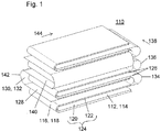
- FIG. 1 is a perspective view of a first embodiment of an electrode assembly 110 shown.
- the electrode arrangement 110 comprises a layer structure comprising a first electrode 112, which is also referred to below as an "anode” and which is guided in the form of a first conductive track 114 together with a separator 116, which is in the form of an insulating track 118.
- Each two adjacent layers 120, 122 of the first conductive path 114 form a double layer 124, wherein between each double layer 124 and a further double layer 126 adjacent thereto, a second layer 128 of the second electrode 130, which is also referred to below as "cathode", is incorporated as part of a second conductive track 132.
- the first conductive trace 114 of the first electrode 112 is folded together with the insulating trace 118 of the separator 116 in the form of a first zigzag fold, thereby forming a plurality of superimposed first layers 120, 122 and opposing first fold edges 134 , 136 of the first zigzag convolution.
- the opposing first folding edges 134, 136 define a first folding direction 138 of the first zigzag folding.
- the second conductive path is folded in a second zigzag folding, which forms a plurality of superimposed second layers 128, 140, here also opposite second fold edges 142 define a second folding direction 144.
- both the first layers 120, 122 and the second layers 128, 140 are arranged parallel to one another, while the first folding direction 138 and the second folding direction 144 assume an angle of 90 ° to one another in the present exemplary embodiment.
- first electrode 112 as an anode in the form of a first conductive path 114 together with a separator 116 in the form of an insulating sheet 118.
- the first conductive track 114 has a first side 146, wherein the first side 146 is coated with an active material in areas 148, which are each separated by gaps 150.
- the coating gaps 150 differ in width along the first conductive trace 114, with a small coating gap 152 particularly for folding the first conductive trace Web 114 is adapted to a plurality of superimposed layers 120, 122, in order to avoid a detachment of active material in the first folded edges 134, 136.
- a large coating gap 154 is also needed for folding in the formation of the layer structure of the electrode assembly 110, but may later serve to attach a trap to the first electrode 112.
- the second side 156 of the first conductive track 114 in this embodiment remains free of a coating of active material.
- the first side 146 of the first electrode 112 is placed on the separator 116, which completely covers the first side 146, while the second, uncoated side 156 of the first electrode 114 lies on top and is therefore freely accessible is.
- This assembly comprising the first conductive sheet 114 and the separator 116 is then folded such that the uncoated second sides 156 of two adjacent first sheets 120, 122 can directly contact and the insulating sheet 118 comes to rest.
- a second layer 128 of the second conductive web 130 is then placed perpendicularly thereto, which is used here as a cathode, without restriction of generality, and which, as in FIG. 2 b) shown, on two identically designed sides 158, 160, which are applied in in separate through coating gaps 150 areas 148 of corresponding active material, has.
- the merged web of the first conductive web 114 and the insulating web 118 is then folded, which in turn places two uncoated second sides 156 of the anode web 114 one over the other and the separator web 118 in turn gets on top of the stack.
- the cathode web 132 is again placed on this separator web 118 at the top by folding.
- the layer structure of the electrode assembly 110 can be continued as long as there are enough tracks available or, for whatever reason, the method is aborted.
- An inventive layer structure is exemplified in FIG. 3 shown. While a first arrester can be attached to the first fold edges 134, 136 of the first electrode 112, the uncoated edge strip 162 is available for attaching the second arrester to the cathode 130 the cathode web 132 protrudes laterally a few millimeters from the sealing structure of the electrode assembly 110. That way it will, like FIG. 3 shows, it is possible to attach the two arresters opposite one another to the electrode arrangement 110.
- cathode and anode can be reversed.
- a cathode coated only on the first side is used, while the anode then has a coating on the second side, as shown in FIG. 2B for the cathode, and the second side of the cathode remains free of a coating of active material.
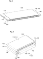
- FIGS. 4 to 6 show a second embodiment of an electrode assembly and a method for its preparation, this embodiment of which in the FIGS. 1 to 3 illustrated embodiment only differs in the final attachment options for the arrester.
- the illustrated method for forming the layer structure is the same, so that in this regard reference is made to the description of the first embodiment. Also in this embodiment, it is possible, as described above for the first embodiment, to exchange the role of cathode and anode.
- both the first side 158 and the second side 160 of the second conductive track 132 each have a coating with active material, wherein the areas provided with the active material 148 alternately through the small coating gaps 152 and the large coating gaps 154 are separated from each other.
- the two different coating gaps 152, 154 are needed to fold the second conductive trace 132, with the large coating gaps 154 provided at those locations where the drain is to be later attached, which is particularly advantageous for the reasons discussed above.
- FIG. 7 an embodiment of an inventive electrode assembly 110 is shown schematically in perspective view.
- a three-ply web 164 is used, which comprises three superimposed layers of an insulating web 118, preferably according to FIG. 2B on both sides 158, 160 coated second conductive trace 132 and another insulating trace 118.
- the anode web 114 is placed vertically, with the on the first side 146 of the anode sheet 114 according to FIG. 2 equally present regions 148, which carry a coating of the active material, is oriented toward the separator web 118 and is concealed by it.
- the individually guided anode web 114 is then folded such that the uncoated sides 156 of the anode web 114 come to lie on each other and touch each other.
- the three-ply web 164 is subsequently laid out of the separator web 118, the cathode web 132 and the further separator web 118, as a result of which the previously upper anode web 114 is again completely covered with separator 116.
- the layer structure of the electrode assembly 110 can be continued by repeating the above-mentioned method steps until a termination.
- the uncoated edge region 162 of the cathode web 132 which protrudes laterally a few millimeters from the electrode assembly 110, is used. Also in this embodiment, it is possible, as already described above for the first embodiment, to interchange the role of cathode and anode, wherein it is necessary for this, each one, as in FIG. 2 make coating shown.
Description
Die vorliegende Erfindung betrifft eine Elektrodenanordnung, ein Verfahren zu ihrer Herstellung sowie eine elektrochemische Zelle, welche mindestens eine derartige Elektrodenanordnung umfasst. Darüber hinaus betrifft die vorliegende Erfindung ein Verfahren zur Herstellung der elektrochemischen Zelle sowie eine Sekundärbatterie, welche mindestens eine derartige elektrochemische Zelle umfasst.The present invention relates to an electrode assembly, a method for its production, and an electrochemical cell comprising at least one such electrode assembly. Moreover, the present invention relates to a method for producing the electrochemical cell and a secondary battery comprising at least one such electrochemical cell.
Aus dem Stand der Technik ist eine Vielzahl von Batterien bekannt, worunter üblicherweise eine elektrische Zusammenschaltung von mindestens zwei elektrochemischen Zellen, welche auch als galvanische Zellen bezeichnet werden, verstanden wird, welche vorzugsweise zur Speicherung chemischer Energie und zur Abgabe elektrischer Energie eingesetzt wird. Neben so bezeichneten "Primärbatterien", welche sich in Bezug auf ihren Lebenszyklus lediglich einmalig einsetzen lassen, existiert eine Vielzahl von so genannten "Sekundärbatterien", die sich über eine Vielzahl von Zyklen mit elektrischer Energie laden und entladen lassen. Hierfür ist ein Einsatz von geeigneten Aktivmaterialien erforderlich, welche sich reversibel zwischen mindestens zwei elektronischen Zuständen umwandeln lassen, um auf diese Weise chemische Energie in elektrische Energie bzw. umgekehrt umsetzen zu können.A variety of batteries are known from the prior art, which is usually understood as an electrical interconnection of at least two electrochemical cells, which are also referred to as galvanic cells, which is preferably used for storing chemical energy and for the delivery of electrical energy. In addition to so-called "primary batteries", which can be used only once in terms of their life cycle, there are a variety of so-called "secondary batteries" that load and discharge over a variety of cycles with electrical energy. For this purpose, a use of suitable active materials is required, which can be reversibly convert between at least two electronic states, in order to be able to convert chemical energy into electrical energy or vice versa in this way.
Als "elektrochemische Zelle" wird üblicherweise eine Einrichtung benannt, welche zwei räumlich voneinander getrennte Elektroden umfasst, und zwar eine erste Elektrode und eine zweite Elektrode, die jeweils eine verschiedene Polarität aufweisen und daher auch als "Kathode" bzw. als "Anode" bezeichnet werden. In der elektrochemischen Zelle stehen die beiden Elektroden zum einen über mindestens einen ionenleitenden Elektrolyten miteinander in Kontakt, während ein für die Ionen durchlässiger Separator die beiden Elektroden elektrisch voneinander isoliert, um einen Kurzschluss zu vermeiden. Mit anderen Worten: Die elektrochemische Zelle verfügt in der Regel über eine so genannte "Elektrodenanordnung", welche auch als "Elektroden-Separator-Anordnung" bezeichnet wird und welche mindestens eine erste Elektrode, mindestens eine zweite Elektrode und mindestens einen Separator umfasst, wobei die Elektrodenanordnung wenigstens mit dem mindesten einen Elektrolyten und mit mindestens einem elektrischen Ableiter für jede der beiden Elektroden versehen ist.As "electrochemical cell" usually a device is named, which comprises two spatially separated electrodes, namely a first electrode and a second electrode, each having a different polarity and therefore also referred to as "cathode" or as "anode" , In the electrochemical cell, the two electrodes are in contact with one another via at least one ion-conducting electrolyte, while a separator which is permeable to the ions electrically isolates the two electrodes from one another in order to avoid a short circuit. In other words, the electrochemical cell generally has a so-called "electrode arrangement", which is also referred to as "electrode-separator arrangement" and which comprises at least a first electrode, at least one second electrode and at least one separator, wherein the Electrode assembly is provided at least with the at least one electrolyte and at least one electrical arrester for each of the two electrodes.
Aus dem Stand der Technik ist eine Vielzahl von Elektrodenanordnungen bekannt. Die
Da der Separator in vielen Fällen in Form eines isolierenden Bandes, welches beispielsweise als Membran ausgestaltet sein kann, vorliegt, werden elektrochemische Zellen beschrieben, in welchen der Separator als isolierende Bahn in Form einer so genannten "Zickzack-Faltung" oder "Z-Faltung" gelegt ist, wobei durch die Zickzack-Faltung eine Mehrzahl von übereinander liegenden Lagen ausgebildet ist, zwischen denen jeweils abwechselnd eine Kathodenplatte und eine Anodenplatte eingefügt ist. Eine derartige Ausgestaltung der elektrochemischen Zelle findet sich beispielsweise in
Aus der
Die
Insbesondere im Fall von Lithium-Ionenbatterien werden häufig Elektroden aus einem metallischen Material wie beispielsweise Kupfer oder Aluminium eingesetzt, auf die jeweils eine Schicht aus einem Aktivmaterial aufgebracht ist, wobei das Aktivmaterial ein Lithium-haltiges Anoden- oder Kathodenmaterial umfasst. Eine Übersicht über gebräuchliche Materialien auf dem Gebiet der Lithiumionen-Batterien findet sich in
Wie aus B. Ketterer, s.o., weiterhin hervorgeht, umfassen bekannte Kathodenmaterialien, die als Aktivmaterialien für Lithiumionen-Batterien eingesetzt werden, in der Regel Interkalationsverbindungen aus anorganischen Übergangsmetalloxiden, welche sich gemäß der Dimensionalität einer Wirtsstruktur für eine Lithiumionendiffusion in der Interkalationsverbindung in eindimensionale Röhren-Strukturen, in zweidimensionale Schicht-Strukturen und in dreidimensionale Rahmen-Strukturen untergliedern lassen. Zu den Verbindungen mit eindimensionaler Röhren-Struktur zählen Übergangsmetallverbindungen, etwa LiFePO4 mit Olivin-Struktur. Die zweidimensionalen Schichtstrukturen umfassen insbesondere LiMo2 mit M = Co, Mi, Fe oder Mn, wobei insbesondere die Verbindungen LiNi0,85Co0,1Al0,05O2, LiNi1/3Co1/3Mn1/3O2 oder Li-Ni1/2Mn1/2O2 eingesetzt werden. Verbindungen mit Spinell-Struktur, wie beispielsweise LiMn2O4, bieten ein dreidimensionales Netzwerk zur Einlagerung der Lithium-Ionen.As is further apparent from B. Ketterer, supra, known cathode materials used as active materials for lithium-ion batteries typically include inorganic transition-metal oxide intercalation compounds which can be made into one-dimensional tubulars according to the dimensionality of a host structure for lithium ion diffusion in the intercalation compound. Structures, in two-dimensional layer structures and in three-dimensional frame structures can be divided. Compounds with one-dimensional tube structure include transition metal compounds, such as olefin-based LiFePO 4 . The two-dimensional layer structures comprise in particular LiMo 2 with M = Co, Mi, Fe or Mn, in particular the compounds LiNi 0.85 Co 0.1 Al 0.05 O 2 , LiNi 1/3 Co 1/3 Mn 1/3 O 2 or Li-Ni 1/2 Mn 1/2 O 2 are used. Spinelated compounds, such as LiMn 2 O 4 , provide a three-dimensional network for the incorporation of lithium ions.
Die
Die
Allgemein werden Elektrodenanordnungen gefordert, welche bei gleichzeitig verbesserter Sicherheit mehr Leistung bzw. Energie bei höheren Spannungen bereitstellen sollen. Im Falle von Lithiumionenbatterien weisen die bekannten Elektrodenanordnungen insbesondere aufgrund des hierbei auftretenden Ausdehnungsverhaltens der eingesetzten Materialien Nachteile auf, insbesondere da sich dort oftmals bereits nach kurzer Betriebszeit Fehlfunktionen, wie etwa ein hoher Innenwiderstand, ausbilden können. So ist etwa von Lithiumionenbatterien bekannt, dass Abscheidungen aus metallischem Lithium oder anderen Materialien wie beispielsweise Eisen in Form von baumartigen Strukturen, so genannten "Dendriten", oder auch in Form von flächigen Strukturen zu einem Kurzschluss und damit zu einem völligen Fehlversagen der Elektrodenanordnung und der elektrochemischen Zelle, in welcher sich die betroffene Elektrodenanordnung befindet, führen können. Beispielsweise können Dendriten als fein gegliederte Strukturen nadelhaft eine Elektrodenanordnung durchstoßen und auf diese Weise einen Kurzschluss herbeiführen. Alternativ und/oder zusätzlich können sich Dendriten aber auch um Faltkanten herum ausbilden, wodurch sich ebenfalls ein Kurzschluss ausbilden kann. Flächig abgeschiedenes Lithium kann darüber hinaus eine möglicherweise unerwünschte elektrisch leitfähige Verbindung von einer Elektrode zu dem Elektrolyten ausbilden. Auch auf diese Weise kann die Lebensdauer einer Batterie, welche mindestens eine derart schadhafte Elektrodenanordnung aufweist, signifikant verringert werden.In general, electrode assemblies are required, which should provide more power or energy at higher voltages with simultaneously improved safety. In the case of lithium-ion batteries, the known electrode arrangements, in particular due to the In this case occurring expansion behavior of the materials used disadvantages, especially since there often malfunction, such as a high internal resistance can form already after a short period of operation. For example, it is known from lithium-ion batteries that deposits of metallic lithium or other materials such as iron in the form of tree-like structures, so-called "dendrites", or even in the form of flat structures to a short circuit and thus to a complete failure of the electrode assembly and the electrochemical cell in which the affected electrode assembly is located, can lead. For example, dendrites as finely structured structures can needle-like penetrate an electrode arrangement and thus cause a short circuit. Alternatively and / or additionally, however, dendrites can also form around folding edges, as a result of which a short circuit can likewise be formed. Flat deposited lithium In addition, it may form a potentially undesirable electroconductive compound from an electrode to the electrolyte. Also in this way, the life of a battery having at least one such defective electrode arrangement can be significantly reduced.
Die Aufgabe der vorliegenden Erfindung besteht darin, eine Elektrodenanordnung, ein Verfahren zu ihrer Herstellung und eine elektrochemische Zelle bereitzustellen, welche die aus dem Stand der Technik bekannten Nachteile und Einschränkungen zumindest teilweise überwinden.The object of the present invention is to provide an electrode assembly, a process for its production and an electrochemical cell which at least partially overcome the disadvantages and limitations known from the prior art.
Insbesondere soll eine Elektrodenanordnung und eine elektrochemische Zelle, die eine derartige Elektrodenanordnung umfasst, bereitgestellt werden, in welcher mögliche Veränderungen der Struktur, etwa durch die Dendritenbildung und die flächige Abscheidung aus Aktivmaterialien, möglichst weitgehend unterdrückt ist und welche sich bei dadurch verbesserter Sicherheit für den Einsatz in Sekundärbatterien mit höherer Leistung bzw. Energie eignen.In particular, an electrode arrangement and an electrochemical cell comprising such an electrode arrangement are to be provided, in which possible changes in the structure, for example by the dendrite formation and the planar deposition of active materials, are suppressed as far as possible and which results in improved safety for use in secondary batteries with higher power or energy are suitable.
Weiterhin soll insbesondere ein Verfahren zur Herstellung der Elektrodenanordnung vorgeschlagen werden, welches eine effiziente Herstellung der Elektrodenanordnung und/oder der elektrochemischen Zelle unter einer möglichst geringen Anzahl an Verfahrensschritten erlaubt.Furthermore, in particular, a method for producing the electrode arrangement is to be proposed, which allows efficient production of the electrode arrangement and / or the electrochemical cell with the least possible number of method steps.
Diese Aufgabe wird gelöst durch eine Elektrodenanordnung, ein Verfahren zu ihrer Herstellung sowie durch eine elektrochemische Zelle mit den Merkmalen der unabhängigen Patentansprüche. Bevorzugte Ausgestaltungen, welche einzeln oder in Kombination realisierbar sind, sind in den abhängigen Patentansprüchen dargestellt.This object is achieved by an electrode assembly, a method for their preparation and by an electrochemical cell having the features of the independent claims. Preferred embodiments, which can be implemented individually or in combination, are shown in the dependent claims.
Im Folgenden werden die Begriffe "haben", "aufweisen", "umfassen" oder "einschließen" oder beliebige grammatikalische Abweichungen davon in nicht-ausschließlicher Weise verwendet. Dementsprechend können sich diese Begriffe sowohl auf Situationen beziehen, in welchen, neben dem durch diese Begriffe eingeführten Merkmal, keine weiteren Merk-male vorhanden sind, oder auf Situationen, in welchen ein oder mehrere weitere Merkmale vorhanden sind. Beispielsweise kann sich der Ausdruck "A hat B", "A weist B auf, "A umfasst B" oder "A schließt B ein" sowohl auf die Situation beziehen, in welcher, abgesehen von B, kein weiteres Element in A vorhanden ist (d.h. auf eine Situation, in welcher A ausschließlich aus B besteht), als auch auf die Situation, in welcher, zusätzlich zu B, ein oder mehrere weitere Elemente in A vorhanden sind, beispielsweise Element C, Elemente C und D oder sogar weitere Elemente.Hereinafter, the terms "having", "having", "including" or "including" or any grammatical variations thereof are used in a non-exclusive manner. Accordingly, these terms may refer to situations in which, in addition to the feature introduced by these terms, there are no other features, or to situations in which one or more other features are present. For example, the expression "A has B", "A has B," A includes B "or" A includes B "can both refer to the situation in which, apart from B, there is no further element in A ( ie a situation in which A consists exclusively of B), as well as the situation in which, in addition to B, one or more further elements in A are present, for example element C, elements C and D or even further elements.
Die vorliegende Erfindung umfasst in einem ersten Aspekt eine Elektrodenanordnung, die über einen Schichtaufbau mit mindestens einer ersten Elektrode, mindestens einer zweiten Elektrode und mindestens einem zwischen der ersten Elektrode und der zweiten Elektrode eingebrachten Separator verfügt. Unter der "ersten Elektrode" wird hierbei ein erstes, elektrisch leitfähiges Material verstanden, das erfindungsgemäß in Form mindestens einer ersten elektrisch leitfähigen Bahn vorliegt. Eine analoge Anforderung gilt auch für die "zweite Elektrode", die als zweites elektrisch leitfähiges Material in Form mindestens einer elektrisch leitfähigen Bahn vorliegt. Die beiden Elektroden unterscheiden sich hierbei in Bezug auf ihre Polarität, so dass für den Fall, dass es sich bei der ersten Elektrode um eine Anode handelt, die zweite Elektrode eine Kathode darstellt. Handelt es sich umgekehrt bei der ersten Elektrode um eine Kathode, so stellt die zweite Elektrode demnach eine Anode dar. Als "Anode" wird hierbei - im Einklang mit der üblichen Definition - diejenige Elektrode bezeichnet, an welcher eine Oxidation ablaufen kann, wodurch Elektronen von der Anode über einem Ableiter abfließen können, während sich in einem Elektrolyten vorhandene Anionen zur Anode bewegen können, um insbesondere auf Zwischengitterplätzen in einem Aktivmaterial, welches die Anode umfasst, eingelagert werden zu können. Als "Kathode" wird demgegenüber diejenige Elektrode bezeichnet, an welcher eine Reduktion ablaufen kann, wodurch Elektronen über einen Ableiter zur Kathode hinfließen können, während sich in den Elektrolyten befindliche Kationen ebenfalls zur Kathode bewegen können. Solange die beiden Elektroden eine voneinander unterschiedliche Polarität aufweisen, ist es für die erfindungsgemäße Elektrodenanordnung unerheblich, welche der beiden Elektroden, d.h. die erste Elektrode oder die zweite Elektrode, tatsächlich eine Kathode oder eine Anode darstellt.In a first aspect, the present invention comprises an electrode arrangement which has a layer structure with at least one first electrode, at least one second electrode and at least one separator introduced between the first electrode and the second electrode. In this case, the "first electrode" is understood to mean a first, electrically conductive material which according to the invention is present in the form of at least one first electrically conductive path. An analogous requirement also applies to the "second electrode", which is present as a second electrically conductive material in the form of at least one electrically conductive path. The two electrodes differ in terms of their polarity, so that in the event that the first electrode is an anode, the second electrode is a cathode. Conversely, if the first electrode is a cathode, then the second electrode is an anode. Here, in accordance with the customary definition, an "anode" is the electrode on which an oxidation can take place, whereby electrons from the anode can flow away via an arrester, while anions present in an electrolyte can move to the anode in order to be able to be stored, in particular, at interstice sites in an active material which comprises the anode. In contrast, the term "cathode" refers to that electrode on which a reduction can take place, as a result of which electrons can flow to the cathode via an arrester, while cations present in the electrolyte can likewise move to the cathode. As long as the two electrodes have a mutually different polarity, it is irrelevant for the electrode arrangement according to the invention which of the two electrodes, i. the first electrode or the second electrode actually represents a cathode or an anode.
Erfindungsgemäß weist jede der beiden Elektroden jeweils eine elektrisch leitfähige Bahn auf. Hierunter ist ein flacher flexibler Körper aus einem elektrisch leitfähigen Material zu verstehen, welcher insbesondere in Form einer Rolle bereitgestellt werden kann. Durch diese Art der Formgebung wird hierbei die Dimensionen der Bahn derart festgelegt, dass die Länge der Bahn sehr viel größer ist als die Breite der Bahn, während die Breite der Bahn sehr viel größer ist als die Dicke der Bahn. Die Länge der Bahn kann hierbei die Breite der Bahn um einen Faktor 10, 100, 1000 oder mehr übertreffen, während die Breite der Bahn die Dicke der Bahn um einen Faktor 10, 20, 50, 100 oder mehr überschreiten kann. Die Bahn kann insbesondere in Form einer Metallfolie, eines dünnen Bandes, eines Streckmetalls und/oder einer gewebten Netzstruktur vorliegen, welche jeweils ein elektrisch leitfähiges Material, insbesondere ein Metall oder eine Legierung aufweisen. In einer bevorzugten Ausgestaltung umfasst die erste leitfähige Bahn eine erste Metallbahn, welche mindestens ein erstes Metall oder eine erste Legierung aufweist, insbesondere Kupfer. In dieser Ausgestaltung kann die zweite leitfähige Bahn eine zweite Metallbahn aufweisen, welche mindestens ein von dem ersten Metall oder ersten Legierung unterschiedliches zweites Metall, insbesondere Aluminium, oder eine hiervon verschieden Legierung umfassen kann.According to the invention, each of the two electrodes in each case has an electrically conductive path. This is to be understood as meaning a flat, flexible body of an electrically conductive material, which can be provided in particular in the form of a roll. By this type of shaping, the dimensions of the web are determined such that the length of the web is much greater than the width of the web, while the width of the web is much greater than the thickness of the web. The length of the web can thereby exceed the width of the web by a factor of 10, 100, 1000 or more, while the width of the web can exceed the thickness of the web by a factor of 10, 20, 50, 100 or more. The web may in particular be in the form of a metal foil, a thin band, an expanded metal and / or a woven network structure, which each comprise an electrically conductive material, in particular a metal or an alloy. In a preferred embodiment, the first conductive path comprises a first metal track which has at least one first metal or a first alloy, in particular copper. In this embodiment, the second conductive trace may comprise a second metal trace which is at least one different from the first metal or first alloy second metal, in particular aluminum, or a different alloy may include.
Weiterhin umfasst die Elektrodenanordnung einen, zwischen der ersten Elektrode und der zweiten Elektrode eingebrachten Separator, welcher in Form mindestens einer elektrisch isolierenden Bahn vorliegt. Unter einem "Separator" ist hierbei eine elektrisch isolierende Einrichtung zu verstehen, welche die erste und die zweite Elektrode derart voneinander trennt und insbesondere für diesen Zweck auf einem gegenseitigen Abstand hält, damit die beiden Elektroden keinen direkten Kontakt miteinander aufbauen können, vorzugsweise um einen Kurzschluss in Folge einer direkten, elektrisch leitfähigen Verbindung zwischen den beiden Elektroden zu vermeiden. Die Form der isolierenden Bahn kann hierbei vorzugsweise der Form mindestens einer der elektrisch leitfähigen Bahn, wie oben oder unten beschrieben, entsprechen oder sie kann auch eine größerer Breite aufweisen, die über die mindestens eine elektrisch leitfähige Bahn hinausragt. Insbesondere kann die isolierende Bahn einen Kunststoff, etwa ein Polyolefin, und/oder einen keramischen Werkstoff umfassen, wobei der Kunststoff und/oder der keramische Werkstoff in einer besonders bevorzugten Ausgestaltung Poren aufweisen können, die etwa zur Aufnahme des für die elektrochemische Zelle erforderlichen Elektrolyten eingerichtet sind und zur Durchströmung durch die Lithium-Ionen dienen.Furthermore, the electrode arrangement comprises a separator which is introduced between the first electrode and the second electrode and which is in the form of at least one electrically insulating track. A "separator" here is to be understood as meaning an electrically insulating device which separates the first and second electrodes from one another and keeps them at a mutual distance, in particular for this purpose, so that the two electrodes can not establish direct contact with each other, preferably by a short circuit as a result of a direct, electrically conductive connection between the two electrodes to avoid. The shape of the insulating web may in this case preferably correspond to the shape of at least one of the electrically conductive web, as described above or below, or it may also have a greater width, which protrudes beyond the at least one electrically conductive web. In particular, the insulating web may comprise a plastic, such as a polyolefin, and / or a ceramic material, wherein the plastic and / or the ceramic material in a particularly preferred embodiment may have pores, which are arranged approximately for receiving the required for the electrochemical cell electrolyte are and serve to flow through the lithium ions.
In einer bevorzugten Ausgestaltung kann der Separator wenigstens einen Bestandteil aus einem keramischen Werkstoff, wie zum Beispiel Al2O3 und/oder SiO2, aufweisen, welcher insbesondere über eine hohe mechanische Festigkeit, eine hohe Temperaturbeständigkeit und einen geringen Schrumpf bei höheren Temperaturen verfügen kann. In Folge hoher Ströme während des Betriebs einer Elektrodenanordnung kann es mitunter zu einer starken Erwärmung der Elektrodenanordnung kommen, wobei der Separator, insbesondere wenn er aus einem polyolefinen Material gebildet ist, leicht schrumpfen kann, wodurch es zu einem direkten Kontakt zwischen den beiden Elektroden und damit zu einer Überhitzung der Elektrodenanordnung kommen kann, wodurch einen Brand ausgelöst werden kann. Vorzugsweise kann der keramische Separator aus einem biegsamen keramischen Kompositmaterial gebildet sein. Ein Kompositmaterial, das auch als Verbundmaterial bezeichnet werden kann, kann aus verschiedenen, miteinander fest verbundenen Materialien, insbesondere aus keramischen Materialien und aus polymeren Materialien, gebildet sein. Beispielsweise kann sich hierfür ein Vlies aus Polyethylenterephthalat (PET) eigenen, welches mit einer keramischen Imprägnierung und/oder Auflage versehen sein kann.In a preferred embodiment, the separator may comprise at least one component made of a ceramic material, such as Al 2 O 3 and / or SiO 2 , which may in particular have a high mechanical strength, a high temperature resistance and a low shrinkage at higher temperatures , As a result of high currents during the operation of an electrode assembly may sometimes come to a strong heating of the electrode assembly, the separator, especially if it is formed from a polyolefin material, can easily shrink, thereby causing a direct contact between the two electrodes and thus can lead to overheating of the electrode assembly, whereby a fire can be triggered. Preferably, the ceramic separator may be formed of a flexible ceramic composite material. A composite material, which may also be referred to as a composite material, may be formed from various materials bonded together, in particular from ceramic materials and from polymeric materials. For example, this may be a fleece of polyethylene terephthalate (PET) own, which may be provided with a ceramic impregnation and / or support.
Vorzugsweise kann der keramische Separator auf einer Seite und/oder auf beiden Seiten des isolierenden Bandes mit einer ionischen Flüssigkeit benetzt sein, welche insbesondere die Biegsamkeit des keramischen Separators erhöhen und seine Anhaftung an mindestens einer der beiden Elektroden der Elektrodenanordnung verbessern kann.Preferably, the ceramic separator may be wetted on one side and / or on both sides of the insulating tape with an ionic liquid, which in particular can increase the flexibility of the ceramic separator and improve its adhesion to at least one of the two electrodes of the electrode assembly.
Vorteilhaft kann sich der mindestens eine Separator wenigstens teilweise über eine Begrenzungskante wenigstens einer insbesondere benachbarten Elektrode, besonders bevorzugt über sämtliche Begrenzungskanten insbesondere benachbarter Elektroden hinaus, erstrecken. In dieser Ausgestaltung können sich etwaige elektrische Ströme zwischen den Kanten von Elektroden der Elektrodenanordnung verringern lassen.Advantageously, the at least one separator may extend at least partially beyond a boundary edge of at least one in particular adjacent electrode, particularly preferably beyond all boundary edges, in particular of adjacent electrodes. In this embodiment, any electrical currents between the edges of electrodes of the electrode assembly can be reduced.
Erfindungsgemäß ist die erste leitfähige Bahn in Form einer ersten Zickzackfaltung gelegt. Unter einer "Zickzack-Faltung", die auch als "Z-Faltung" bezeichnet werden kann, wird hierbei eine, beispielsweise in G. Reinhart, s.o., dargestellte Ausgestaltung der ersten Elektrode verstanden, wobei das erste leitfähige Band jeweils abschnittsweise in Form von übereinander liegenden ersten Lagen gefaltet ist, wobei sich einander gegenüberliegende erste Faltkanten ausbilden. Die Zickzack-Faltung zeichnet sich also dadurch aus, dass ein erster Abschnitt des ersten Bandes, welcher als erste Lage bezeichnet wird, auf eine Unterlage oder auf eine vorherige erste Lage gelegt wird, wobei an einem Ende des Abschnitts das Band insgesamt um 180° umgelegt wird, um auf diese Weise eine weitere Lage des selben Bandes auszubilden, wobei zwischen der ersten Lage und der weiteren Lage dadurch über die Breite des Bandes eine Faltkante ausgebildet ist. Diese Art der Anordnung ist über zumindest einen Teil des Bandes, insbesondere das gesamte Band, vorzugsweise in gleicher Weise ausgeführt, so dass die erste leitfähige Bahn in Form einer Mehrzahl von parallel übereinander liegenden, ersten Lagen vorliegt.According to the invention, the first conductive track is laid in the form of a first zigzag fold. A "zigzag folding", which can also be referred to as a "Z-folding", is understood to mean a configuration of the first electrode shown in G. Reinhart, for example, wherein the first conductive strip is in sections in the form of one above the other folded first layers is formed, forming opposite first fold edges. The zigzag folding is thus characterized in that a first section of the first band, which is referred to as the first layer, is placed on a base or on a previous first layer, wherein at one end of the section, the band is folded over a total of 180 ° is in order to form in this way a further layer of the same band, wherein between the first layer and the further layer characterized over the width of the band, a fold edge is formed. This type of arrangement is preferably carried out in the same way over at least part of the band, in particular the entire band, so that the first conductive band is in the form of a plurality of first layers lying parallel one above the other.
Die Elektrodenanordnung umfasst weiterhin eine zweite leitfähige Bahn, welche in Form einer zweiten Zickzack-Faltung gelegt ist, wodurch durch die zweite Zickzack-Faltung, in Analogie zu der ersten Zickzack-Faltung, eine Mehrzahl von parallel übereinander liegenden zweiten Lagen ausgebildet ist, wobei zwei unmittelbar aneinander grenzende Lagen des zweiten leitfähigen Bandes jeweils über die Breite des zweiten leitfähigen Bandes eine zweite Faltkante ausbilden.The electrode arrangement furthermore comprises a second conductive track, which is laid in the form of a second zigzag folding, whereby a second plurality of parallel superimposed second layers is formed by the second zigzag folding, in analogy to the first zigzag folding form directly adjacent layers of the second conductive tape respectively over the width of the second conductive tape a second fold edge.
Erfindungsgemäß sind nun das erste leitfähige Band und das zweite leitfähige Band derart in die Elektrodenanordnung eingebracht, dass die ersten Lagen und die zweiten Lagen parallel zueinander ausgerichtet sind. Wird durch die einander gegenüber liegenden ersten Faltkanten der ersten Zickzack-Faltung eine erste Faltrichtung der ersten Zickzack-Faltung und durch einander gegenüber liegende zweite Faltkante in der zweiten Zickzack-Faltung eine zweite Faltrichtung der zweiten Zickzack-Faltung definiert, so nehmen die erste Faltrichtung und die zweite Faltrichtung einen Winkel zueinander ein, der erfindungsgemäß in einem Bereich von mindestens 60° und von höchstens 120°, vorzugsweise von mindestens 80° und höchstens von 100°, liegt, wobei der Winkel besonders bevorzugt einen Wert von 90° annimmt.According to the invention, the first conductive band and the second conductive band are now introduced into the electrode arrangement such that the first layers and the second layers are aligned parallel to one another. If a first folding direction of the first zigzag folding is defined by the opposing first folding edges of the first zigzag folding and a second folding direction of the second zigzag folding by opposing second folding edge in the second zigzag folding, the first folding direction and the second folding direction at an angle to one another, which is according to the invention in a range of at least 60 ° and at most 120 °, preferably at least 80 ° and at most 100 °, wherein the angle particularly preferably assumes a value of 90 °.
Gemäß der vorliegenden Erfindung sind jeweils zwei benachbarte erste Lagen der ersten leitfähigen Bahn derart übereinander gelegt, dass sie dadurch eine Doppellage ausbilden, während jeweils zwischen zwei Doppellagen eine zweite Lage der zweiten leitfähigen Bahn eingebracht ist. Insbesondere in dieser besonders bevorzugten Ausgestaltung, jedoch nicht hierauf beschränkt, können jeweils eine erste leitfähige Bahn und eine isolierende Bahn zusammengeführt sein, dass die erste leitfähige Bahn zusammen mit genau einer isolierenden Bahn eine Mehrzahl von übereinander liegenden ersten Lagen ausbilden kann. Alternativ oder auch zusätzlich hierzu können zwei isolierende Bahnen zusammen mit der zweiten leitfähigen Bahn derart geführt sein, dass sich eine Mehrzahl von übereinander liegenden zweiten Lagen ausbilden kann, wobei hierbei die zweite leitfähige Bahn genau zwischen zwei der isolierenden Bahnen geführt sein kann. Die in diesem Abschnitt beschriebenen Ausgestaltungen können insbesondere sicherstellen, dass sich die beiden elektrisch leitfähigen Elektrodenbahnen durch bevorzugt eine oder zwei isolierende Bahnen derart voneinander trennen lassen, dass ein elektrischer Kontakt zwischen den elektrisch leitfähigen Elektrodenbahnen unterbleiben kann.According to the present invention, each two adjacent first layers of the first conductive path are superimposed in such a way that they thereby form a double layer, while in each case between two double layers, a second layer of the second conductive path is introduced. In particular, in this particularly preferred embodiment, but not limited thereto, in each case a first conductive track and an insulating track can be brought together so that the first conductive track together with exactly one insulating track can form a plurality of superimposed first layers. Alternatively or in addition to this, two insulating tracks may be guided together with the second conductive track such that a plurality of superimposed second layers may form, in which case the second conductive track may be guided exactly between two of the insulating tracks. The embodiments described in this section can in particular ensure that the two electrically conductive electrode tracks can be separated from one another by preferably one or two insulating tracks such that an electrical contact between the electrically conductive electrode tracks can be omitted.
Andere Ausgestaltungen, die festlegen, in welcher Weise die beiden Lagen in der Elektrodenanordnung in Bezug zueinander angeordnet sein können, sind jedoch denkbar. Vorzugsweise kann die Elektrodenanordnung mehr als eine erste Elektrode und mehr als eine zweite Elektrode umfassen, wobei die Elektroden verschiedener Polarität jeweils mittels wenigstens eines Separators voneinander getrennt sind. Insbesondere kann hierbei der Schichtbau in der Elektrodenanordnung jeweils eine Elektrode aufweisen, auf die jeweils ein Separator folgt, der die Elektrode von der nächsten, vorzugsweise mit der anderen Polarität ausgestatteten Elektrode trennt. Vorzugsweise können in dieser Elektroden-anordnung mehrere Elektroden gleicher Polarität jeweils miteinander elektrisch leitend verbunden und vorzugsweise parallel, aber auch in Reihe zueinander geschaltet sein.Other embodiments, however, which determine how the two layers in the electrode arrangement can be arranged with respect to one another, are conceivable. Preferably, the electrode arrangement may comprise more than one first electrode and more than one second electrode, wherein the electrodes of different polarity are each separated from one another by means of at least one separator. In particular, in this case, the layer structure in the electrode arrangement in each case have an electrode, which is followed in each case by a separator which separates the electrode from the next, preferably provided with the other polarity electrode. Preferably, in this electrode arrangement a plurality of electrodes of the same polarity can be electrically conductively connected to each other and preferably connected in parallel, but also in series with each other.
In einer besonders bevorzugten Ausgestaltung kann die erste leitfähige Bahn und/oder die zweite leitfähige Bahn der erfindungsgemäßen Elektrodenanordnung jeweils eine erste Seite und eine zweite Seite aufweisen, wobei die erste Seite und/oder die zweite Seite der elektrisch leitfähigen Bahnen zumindest teilweise mit einem Aktivmaterial versehen sein können. Diese Ausgestaltung kann insbesondere vorsehen, dass übereinander liegende elektrisch leitfähige Bahnen, die nicht durch mindestens eine isolierende Bahn voneinander getrennt sind, nicht mit dem Aktivmaterial beschichtet sein können. Demgemäß kann die erste Seite der ersten leitfähigen Bahn, die erste Seite der zweiten leitfähigen Bahn und die zweite Seite der zweiten leitfähigen Bahn zumindest teilweise mit dem Aktivmaterial versehen sein, während die zweite Seite der ersten leitfähigen Bahn frei von Aktivmaterial bleiben kann. Die Beschichtungen der leitfähigen Bahnen der Elektrodenanordnung können vorzugsweise derart ausgestaltet sein, dass zwischen Bereichen auf der ersten Seite und/oder zwischen Bereichen auf der zweiten Seite, welche jeweils mit dem Aktivmaterial versehen sind, Lücken vorgesehen sind, welche vorzugsweise zumindest an den ersten Faltkanten und an den zweiten Faltkanten sowie an Kontaktierungsbereichen auftreten können. Unter "Kontaktierungsbereichen" werden Bereiche auf der ersten leitfähigen Bahn und/oder auf der zweiten leitfähigen Bahn verstanden, die für eine spätere Kontaktierung mit jeweils einem Ableiter, welcher den elektrischen Kontakt zu der ersten Elektrode bzw. zu der zweiten Elektrode herstellen kann, vorgesehen sind. Die Kontaktierungsbereiche liegen an Randbereichen, über welche die erste leitfähige Bahn und/oder die zweite leitfähige Bahn verfügen. Insbesondere für einen Einsatz als Kontaktierungsbereich kann der Randbereich zumindest teilweise Lücken aufweisen; Lücken in dem Randbereich können jedoch auch von Vorteil sein, etwa um zu vermeiden, dass sich Aktivmaterial vom Rand der ersten leitfähigen Bahn und/oder der zweiten leitfähigen Bahn ablösen kann.In a particularly preferred embodiment, the first conductive path and / or the second conductive path of the electrode arrangement according to the invention each have a first side and a second side, wherein the first side and / or the second side of the electrically conductive paths at least partially provided with an active material could be. In particular, this embodiment can provide that electrically conductive tracks which lie one above the other and are not separated from one another by at least one insulating track can not be coated with the active material. Accordingly, the first side of the first conductive path, the first side of the second conductive path, and the second side of the second conductive path may be at least partially provided with the active material, while the second side of the first conductive path may be free of active material. The coatings of the conductive paths of the electrode assembly may preferably be configured such that between regions on the first side and / or between regions on the second side, which in each case with the active material are provided, gaps are provided, which may preferably occur at least at the first fold edges and at the second fold edges and at Kontaktierungsbereichen. "Contacting areas" are understood to be areas on the first conductive path and / or on the second conductive path, which are provided for subsequent contacting with a respective arrester, which can make the electrical contact to the first electrode or to the second electrode , The contacting regions are located at edge regions, which have the first conductive path and / or the second conductive path. In particular, for use as a contacting region, the edge region may at least partially have gaps; However, gaps in the edge region may also be beneficial, such as to prevent active material from detaching from the edge of the first conductive trace and / or the second conductive trace.
Unter einem "Aktivmaterial" wird im Falle der vorliegenden Erfindung, je nachdem, ob mit dem Aktivmaterial die Kathode oder die Anode beschichtet sein kann, ein Lithium-haltiges anorganisches Übergangsmetalloxid bzw. Graphit verstanden. Für geeignete Aktivmaterialien wird in diesem Zusammenhang vorzugsweise auf die in B. Ketterer, siehe oben, vorgestellten Materialien verwiesen, wobei sich für die Ausgestaltung der erfindungsgemäßen Elektrodenanordnung auch weitere, aus dem Einsatz in anderen elektrochemischen Zellen bekannte Materialien eignen können.In the case of the present invention, an "active material" is understood to mean a lithium-containing inorganic transition metal oxide or graphite, depending on whether the cathode or the anode can be coated with the active material. For suitable active materials, reference is made in this connection preferably to the materials presented in B. Ketterer, see above, wherein other materials known from use in other electrochemical cells may also be suitable for the configuration of the electrode arrangement according to the invention.
Die vorliegende Erfindung betrifft in einem weiteren Aspekt ein Verfahren zur Herstellung einer Elektrodenanordnung, welche einen Schichtaufbau mit mindestens einer ersten Elektrode, mindestens einer zweiten Elektrode und mindestens einem, zwischen der ersten Elektrode und der zweiten Elektrode eingebrachten Separator umfasst. Das erfindungsgemäße Verfahren umfasst mindestens die im Folgenden beschriebenen Schritte a) bis d), wobei je nach Ausgestaltung weitere Schritte hinzukommen können. Die Schritte a) bis d) werden vorzugsweise in der dargestellten Reihenfolge durchgeführt, wobei sich die Schritte a) und b) vertauschen lassen können. Gemäß Schritt a) wird eine erste Elektrode in Form einer ersten leitfähigen Bahn und gemäß Schritt b) eine zweite Elektrode in Form einer zweiten leitfähigen Bahn bereitgestellt.In a further aspect, the present invention relates to a method for producing an electrode arrangement which comprises a layer structure having at least one first electrode, at least one second electrode and at least one separator introduced between the first electrode and the second electrode. The inventive method comprises at least the steps described below a) to d), which may be added depending on the configuration of further steps. The steps a) to d) are preferably carried out in the order shown, wherein the steps a) and b) can be reversed. According to step a), a first electrode in the form of a first conductive path and according to step b) a second electrode in the form of a second conductive path are provided.
Die Schritte c) und d) werden erfindungsgemäß, je nach gewählter Ausgestaltung, in dieser Reihenfolge oder der umgekehrten Reihenfolge mehrfach wiederholt, wodurch sich eine Mehrzahl von übereinander liegenden ersten Lagen in Form einer ersten Zickzack-Faltung und eine Mehrzahl von übereinander liegenden zweiten Lagen in Form einer zweiten Zickzack-Faltung ausbildet. Die ersten Lagen und die zweiten Lagen werden hierbei so gelegt, dass sie parallel zueinander angeordnet werden. Einander gegenüberliegende erste Faltkanten der ersten Zickzack-Faltung definieren eine erste Faltrichtung der ersten Zickzack-Faltung, während einander gegenüberliegende zweite Faltkanten der zweiten Zickzack-Faltung eine zweite Faltrichtung der zweiten Zickzack-Faltung definieren. Erfindungsgemäß nehmen hierbei die erste Faltrichtung der ersten Zickzack-Faltung und die zweite Faltrichtung der zweiten Zickzack-Faltung einen Winkel von mindestens 60° und von höchstens 120°, vorzugsweise von mindestens 80° und von höchstens 100°, insbesondere von 90°, zueinander ein.The steps c) and d) according to the invention, depending on the selected configuration, repeated several times in this order or the reverse order, resulting in a plurality of superimposed first layers in the form of a first zigzag folding and a plurality of superposed second layers in Forming a second zigzag folding. The first layers and the second layers are in this case placed so that they are arranged parallel to each other. Opposite first fold edges of the first zigzag fold define a first fold direction of the first zigzag fold, while opposite second fold edges of the second zigzag fold define a second fold direction of the second fold fold Define zigzag folding. According to the invention, the first folding direction of the first zigzag folding and the second folding direction of the second zigzag folding make an angle of at least 60 ° and at most 120 °, preferably at least 80 ° and at most 100 °, in particular 90 °, to one another ,
Es werden jeweils zwei benachbarte erste Lagen derart übereinander gelegt, dass sie jeweils eine Doppellage ausbilden, wobei zwischen zwei Doppellagen jeweils eine, insbesondere eine einzige, zweite Lage eingebracht werden kann. Demgemäß kann in dieser Ausgestaltung Schritt c) zweimal hintereinander durchgeführt werden, bevor im Anschluss hieran jeweils Schritt d) ein einziges Mal durchgeführt wird. Andere Ausgestaltungen sind denkbar. Auf diese Weise kann jedoch eine Elektrodenanordnung erhalten werden, welche insbesondere die unten aufgeführten Vorteile aufweisen kann.Each two adjacent first layers are superimposed in such a way that they each form a double layer, wherein between two double layers one, in particular a single, second layer can be introduced. Accordingly, in this embodiment, step c) can be carried out twice in succession, before subsequently step d) is carried out a single time. Other embodiments are conceivable. In this way, however, an electrode arrangement can be obtained, which in particular can have the advantages listed below.
Erfindungsgemäß wird weiterhin der Separator in Form einer isolierenden Bahn bereitgestellt, wobei die isolierende Bahn derart zwischen die erste leitfähige Bahn und die zweite leitfähige Bahn eingebracht wird, dass die isolierende Bahn des Separators die erste leitfähige Bahn von der zweiten leitfähigen Bahn trennt. Auf diese Weise wird ein etwaiger, nachteiliger elektrischer Kontakt zwischen der ersten leitfähigen Bahn und der zweiten leitfähigen Bahn vermieden.According to the invention, the separator is further provided in the form of an insulating sheet, wherein the insulating sheet is interposed between the first conductive sheet and the second conductive sheet such that the insulating sheet of the separator separates the first conductive sheet from the second conductive sheet. In this way, any adverse electrical contact between the first conductive trace and the second conductive trace is avoided.
In einer besonders bevorzugten Ausgestaltung kann hierbei die mindestens eine isolierende Bahn zusammen mit der ersten leitfähigen Bahn und/oder zusammen mit der zweiten leitfähigen Bahn bereitgestellt und insbesondere zusammen mit der jeweils bereitgestellten leitfähigen Bahn gemäß Schritt c) oder gemäß Schritt d) gefaltet werden. In einer ersten bevorzugten Ausgestaltung kann hierbei die erste leitfähige Bahn zusammen mit genau einer der mindestens einen isolierenden Bahn geführt werden. In einer zweiten, ebenfalls bevorzugten Ausgestaltung kann hierzu die zweite leitfähige Bahn zwischen genau zwei der isolierenden Bahnen geführt werden. Diese Ausgestaltungen sind insbesondere dann vorteilhaft, wenn die erste leitfähige Bahn Doppellagen ausbildet, zwischen denen jeweils eine zweite Lage der zweiten leitfähigen Bahn eingebracht ist. Andere Ausgestaltungen sind jedoch denkbar.In a particularly preferred embodiment, in this case the at least one insulating web can be provided together with the first conductive web and / or together with the second conductive web and, in particular, folded together with the respectively provided conductive web according to step c) or according to step d). In a first preferred embodiment, in this case the first conductive track can be guided together with exactly one of the at least one insulating track. In a second, likewise preferred embodiment, for this purpose the second conductive track can be guided between exactly two of the insulating tracks. These embodiments are particularly advantageous when the first conductive path forms double layers, between each of which a second layer of the second conductive path is introduced. Other embodiments are conceivable, however.
Für weitere Einzelheiten in Bezug auf das erfindungsgemäße Verfahren wird auf die oben bzw. unten näher beschriebene Elektrodenanordnung verwiesen, welche mit diesem Verfahren herstellbar ist. Je nach gewählter Ausgestaltung können darüber hinaus weitere, übliche Anoden-, Separator-, Kathodenschichten sowie Elektrolyte in allen möglichen Zusammensetzungen, Schichtdicken und Dimensionierungen verwendet werden. Insbesondere können übliche Kombinationen aus Anoden, Kathoden, Separator und Elektrolyt eingesetzt werden, wie sie in Lithium- Ionen- oder Lithium-Ionen-Polymer-Zellen Verwendung finden.For further details with regard to the method according to the invention, reference is made to the electrode arrangement described in greater detail above or below, which can be produced by this method. Depending on the chosen embodiment, moreover, conventional anode, separator, cathode layers and electrolytes in all possible compositions, layer thicknesses and dimensions can be used. In particular, conventional combinations of anodes, cathodes, separators and electrolytes can be used, as used in lithium-ion or lithium-ion polymer cells.
Die vorliegende Erfindung betrifft in einem weiteren Aspekt eine elektrochemische Zelle, welche zumindest eine Elektrodenanordnung, die oben oder unten beschrieben wird, und/oder eine mit dem erfindungsgemäßen Verfahren hergestellte Elektrodenanordnung umfasst. Die elektrochemische Zelle umfasst weiterhin mindestens einen Elektrolyten, mindestens einen ersten Ableiter für die erste Elektrode und mindestens einen zweiten Ableiter für die zweite Elektrode. Die elektrochemische Zelle kann darüber hinaus weitere Bestandteile aufweisen, insbesondere ein Gehäuse, welches die elektrochemische Zelle zumindest teilweise, vorzugsweise bis auf Öffnungen zur Anbringung von elektrischen Kontakten vollständig, umgeben kann. Unter einem "Gehäuse" wird hierbei ein unter üblichen Bedingungen festes Material verstanden, das insbesondere dazu eingesetzt wird, um die elektrochemische Zelle zumindest teilweise von ihrer Umgebung zu trennen. Darüber hinaus kann das Gehäuse weitere Funktionen ausüben, etwa den Elektrolyten aufzunehmen, vorzugsweise dann, wenn der Elektrolyt zumindest teilweise in flüssiger Form vorliegt, so dass der Elektrolyt in dieser Form auf einfache Weise in das Gehäuse eingebracht, etwa eingegossen, werden kann. Wie eingangs bereits beschrieben, bezeichnet der "Elektrolyt" eine feste oder flüssige Substanz, in welcher sich die Ionen zwischen den Elektroden bewegen können. In einer alternativen, ebenfalls bevorzugten Ausgestaltung kann der Elektrolyt zusammen mit dem Separator bereitgestellt werden, etwa dadurch, dass der Separator mit dem Elektrolyt getränkt sein kann, beispielsweise indem der Elektrolyt in die Poren, über die der Separator verfügen kann, eingebracht ist.In a further aspect, the present invention relates to an electrochemical cell which comprises at least one electrode arrangement described above or below and / or an electrode arrangement produced by the method according to the invention. The electrochemical cell further comprises at least one electrolyte, at least one first arrester for the first electrode and at least one second arrester for the second electrode. The electrochemical cell may moreover comprise further constituents, in particular a housing which may completely surround the electrochemical cell at least partially, preferably except for openings for the attachment of electrical contacts. In this case, a "housing" is understood to mean a material which is solid under customary conditions and which is used, in particular, to at least partially separate the electrochemical cell from its surroundings. In addition, the housing can perform other functions, such as to accommodate the electrolyte, preferably when the electrolyte is at least partially in liquid form, so that the electrolyte can be introduced in this form in a simple manner in the housing, as cast. As already described, the "electrolyte" refers to a solid or liquid substance in which the ions can move between the electrodes. In an alternative, likewise preferred embodiment, the electrolyte can be provided together with the separator, for example by virtue of the fact that the separator can be impregnated with the electrolyte, for example by introducing the electrolyte into the pores which the separator can dispose of.
In einer bevorzugten Ausgestaltung können der erste Ableiter und/oder der zweite Ableiter an Lücken zwischen Bereichen, welche mit dem Aktivmaterial versehen sind, angebracht sein. Hierbei ist der erste Ableiter für die erste Elektrode an einer ersten Faltkante der ersten leitfähigen Bahn angebracht, während der zweite Ableiter für den zweiten Elektrolyten in einem Randbereich der zweiten leitfähigen Bahn angebracht sein.In a preferred embodiment, the first arrester and / or the second arrester may be attached to gaps between areas provided with the active material. Here, the first arrester for the first electrode is attached to a first folding edge of the first conductive path, while the second arrester for the second electrolyte is mounted in an edge area of the second conductive path.
In einer bevorzugten Ausgestaltung kann die elektrochemische Zelle mit einem isolierenden Dämmmaterial umwickelt sein, insbesondere um vorteilhaft den Verbund zu stärken und die Langlebigkeit und Sicherheit des Systems zu verbessern. Diese Ausgestaltung kann vorteilhaft auch der Abscheidung von Materialien aus dem Aktivmaterial, etwa Lithium oder Eisen in Form von Dendriten, entgegenwirken.In a preferred embodiment, the electrochemical cell can be wrapped with an insulating insulating material, in particular to advantageously strengthen the composite and to improve the longevity and safety of the system. This embodiment can advantageously counteract the deposition of materials from the active material, such as lithium or iron in the form of dendrites.
Die vorliegende Erfindung betrifft in einem weiteren Aspekt ein Verfahren zur Herstellung einer elektrochemischen Zelle, wobei mindestens eine oben oder unten beschriebene Elektrodenanordnung, welche mindestens eine erste Elektrode, mindestens eine zweite Elektrode und mindestens einen, zwischen der ersten Elektrode und der zweiten Elektrode eingebrachten Separator umfasst, bereitgestellt wird. Erfindungsgemäß wird die mindestens eine Elektrodenanordnung hierzu mit mindestens einem Elektrolyten, mindestens einem Ableiter für die erste Elektrode und mindestens einem zweiten Ableiter für die zweite Elektrode versehen. In einer besonders bevorzugten Ausgestaltung kann hierzu ein mit dem Elektrolyt getränkter Separator eingesetzt werden. Ebenfalls bevorzugt ist eine Ausgestaltung, bei welcher die mindestens eine Elektrodenanordnung zumindest teilweise von einem Gehäuse umgeben werden kann, wobei das Gehäuse über Anschlüsse für den ersten Ableiter und über Anschlüsse für den zweiten Ableiter verfügen kann. Insbesondere in der letzteren Ausgestaltung kann der Elektrolyt in flüssiger Form bereitgestellt und auf einfache Weise in das Gehäuse eingebracht werden.In a further aspect, the present invention relates to a method for producing an electrochemical cell, wherein at least one electrode arrangement described above or below, comprising at least one first electrode, at least one second electrode and at least one separator introduced between the first electrode and the second electrode is provided. According to the invention, the at least one electrode arrangement is provided for this purpose with at least one electrolyte, at least one arrester for the first electrode and at least one second arrester for the second electrode. In a particularly preferred embodiment, a separator impregnated with the electrolyte can be used for this purpose. Also preferred is an embodiment in which the at least one electrode arrangement can be at least partially surrounded by a housing, wherein the housing can have connections for the first arrester and connections for the second arrester. In particular, in the latter embodiment, the electrolyte can be provided in liquid form and easily introduced into the housing.
Die vorliegende Erfindung betrifft in einer weiteren Ausgestaltung eine Sekundärbatterie, welche mindestens eine elektrochemische Zelle in der oben oder unten beschriebenen Weise umfasst. In einer besonders bevorzugten Ausgestaltung kann hierbei auch die Sekundärbatterie zumindest teilweise von einem Gehäuse umgeben sein, welches über elektrische Anschlüsse verfügen kann.In a further embodiment, the present invention relates to a secondary battery which comprises at least one electrochemical cell in the manner described above or below. In a particularly preferred embodiment, in this case also the secondary battery may be at least partially surrounded by a housing, which may have electrical connections.
Sowohl in Bezug auf die elektrochemische Zelle als auch auf das Verfahren zur Herstellung der elektrochemischen Zelle als auch auf die Sekundärbatterie wird für weitere Einzelheiten auf die oben oder unten stehende detaillierte Beschreibung der Elektrodenanordnung verwiesen.With respect to both the electrochemical cell and the method of manufacturing the electrochemical cell, as well as the secondary battery, reference is made to the above or below detailed description of the electrode assembly for further details.
Die erfindungsgemäße Elektrodenanordnung und eine elektrochemische Zelle, welche eine derartige Elektrodenanordnung aufweist, sowie eine Sekundärbatterie, welche mindestens eine derartige elektrochemische Zelle umfasst, können eine Reihe von Vorteilen aufweisen. Hierbei kann es besonders vorteilhaft sein, dass das erfindungsgemäße Verfahren ein Falten der mindestens einen ersten Elektrode, der mindestens einen zweiten Elektrode und des mindestens einen, zwischen der ersten Elektrode und der zweiten Elektrode eingebrachten Separators aufweist, wobei die erforderliche Stapelfolge auf einfache Weise eingehalten werden kann. Dadurch, dass die beiden Elektroden in Form von leitfähigen Bahnen und der Separator in Form mindestens einer isolierenden Bahn bereitgestellt werden, erübrigt sich das Herstellen und Positionieren von Einzelelektroden, wodurch sich eine wesentliche Quelle von Fehlern im Herstellungsprozess, die sich beispielsweise in Form von Partikelbildung, Schichtrauheit und/oder Rissen in den Einzelelektroden auswirken können, vermeiden lässt. Das erfindungsgemäße Verfahren erlaubt es vielmehr, Stapel von übereinander liegenden ersten Lagen und zweiten Lagen aus den beiden leitfähigen Bahnen auszubilden, ohne dass jeweils einzelne Elektrodenblätter zugeschnitten, gereinigt, bereitgestellt, positioniert und vor elektrostatischer Aufladung geschützt werden müssen. Auf diese Weise kann sich ein zusätzlicher Trocknungsschritt, der üblicherweise in der Trocknung und Reinigung der einzelnen Elektrodenblätter besteht, einsparen lassen.The electrode arrangement according to the invention and an electrochemical cell which has such an electrode arrangement as well as a secondary battery which comprises at least one such electrochemical cell can have a number of advantages. In this case, it may be particularly advantageous that the method according to the invention comprises folding the at least one first electrode, the at least one second electrode and the at least one separator introduced between the first electrode and the second electrode, wherein the required stacking sequence is maintained in a simple manner can. The fact that the two electrodes are provided in the form of conductive tracks and the separator in the form of at least one insulating web eliminates the need to fabricate and position single electrodes, thereby creating a significant source of manufacturing process errors, such as particle formation, Layer roughness and / or cracks in the individual electrodes can affect, avoid. Rather, the method according to the invention makes it possible to form stacks of superimposed first layers and second layers of the two conductive tracks, without each individual electrode blade having to be cut, cleaned, provided, positioned and protected against electrostatic charging. In this way, an additional drying step, which usually consists in the drying and cleaning of the individual electrode sheets, can be saved.
Das erfindungsgemäße Faltverfahren kann demgemäß die Prozesssicherheit und die Geschwindigkeit der Herstellung der Elektrodenanordnungen bei gleichzeitig erhöhter Ausbeute erhöhen. Die gleichzeitige Führung einer leitfähigen Bahn, auf welche bereits das Aktivmaterial in Form einer dünnen Schicht aufgebracht sein kann, zusammen mit mindestens einer isolierenden Separatorbahn kann die oben beschriebenen Fehlerquellen in der Elektrodenanordnung und ihre Folgen signifikant verringern.The folding process according to the invention can accordingly increase the process reliability and the speed of production of the electrode assemblies with simultaneously increased yield. The simultaneous guidance of a conductive path, to which the active material may already be applied in the form of a thin layer, together with at least one insulating separator track, can significantly reduce the error sources in the electrode arrangement described above and their consequences.
Die erfindungsgemäße Ausgestaltung, die erste Faltrichtung der ersten Zickzackfaltung und die zweite Faltrichtung der zweiten Zickzackfaltung in einem Winkel von mindestens 60° und von höchstens 120°, bevorzugt rechtwinklig, zueinander anzuordnen, kann zu einer besseren Fixierung der einzelnen Elektroden innerhalb der Elektrodenanordnung führen und ein mögliches Verrutschen der einzelnen Bestandteile in den Schichtaufbau bei einer Erhöhung der Temperatur verringern. Durch die vorteilhafte Fixierung und/oder die im Wesentlichen orthogonale Anordnung der beiden Faltrichtungen zueinander können insbesondere Mikrorisse vermieden werden, ohne dass bei der Herstellung der Elektrodenanordnung zusätzliche Verfahrensschritte, wie etwa aufwändige Klebungen oder Laminierungen, erforderlich wären. Auf diese Weise können langlebige Elektrodenanordnungen bereitgestellt werden, deren Sicherheit insbesondere durch die Vermeidung von Mikrorissen in den Elektroden und/oder dem Aktivmaterial, verbessert ist. Diese Vorteile der Elektrodenanordnung finden sich entsprechend auch in der elektrochemischen Zelle, welche eine derartige Elektrodenanordnung umfasst sowie in der Sekundärbatterie, die derartige elektrochemische Zellen aufweist.The embodiment according to the invention, the first folding direction of the first zigzag folding and the second folding direction of the second zigzag folding at an angle of at least 60 ° and at most 120 °, preferably at right angles to each other, can lead to a better fixation of the individual electrodes within the electrode arrangement and a reduce possible slippage of the individual components in the layer structure with an increase in the temperature. The advantageous fixation and / or the substantially orthogonal arrangement of the two folding directions relative to each other makes it possible in particular to avoid microcracks without requiring additional method steps, such as elaborate adhesions or laminations, during the production of the electrode arrangement. In this way, long-life electrode arrangements can be provided whose security is improved, in particular by the avoidance of microcracks in the electrodes and / or the active material. Accordingly, these advantages of the electrode arrangement can also be found in the electrochemical cell which comprises such an electrode arrangement and in the secondary battery which has such electrochemical cells.
Zusammengefasst sind die folgenden Ausgestaltungen der vorliegenden Erfindung bevorzugt:
- 1. Elektrodenanordnung, umfassend einen Schichtaufbau mit mindestens einer ersten Elektrode, mindestens einer zweiten Elektrode und mindestens einem zwischen der ersten Elektrode und der zweiten Elektrode eingebrachten Separator, wobei die erste Elektrode mindestens eine erste leitfähige Bahn aufweist, wobei die erste leitfähige Bahn in einer ersten Zickzackfaltung gefaltet ist, wobei durch die erste Zickzackfaltung eine Mehrzahl von übereinander liegenden ersten Lagen ausgebildet ist, wobei einander gegenüberliegende erste Faltkanten der ersten Zickzackfaltung eine erste Faltrichtung der ersten Zickzackfaltung definieren, wobei die zweite Elektrode mindestens eine zweite leitfähige Bahn aufweist, wobei die zweite leitfähige Bahn in einer zweiten Zickzackfaltung gefaltet ist, wobei durch die zweite Zickzackfaltung eine Mehrzahl von übereinander liegenden zweiten Lagen ausgebildet ist, wobei einander gegenüberliegende zweite Faltkanten der zweiten Zickzackfaltung eine zweiten Faltrichtung der zweiten Zickzackfaltung definieren, wobei die ersten Lagen und die zweiten Lagen parallel zueinander angeordnet sind, wobei die erste Faltrichtung und die zweite Faltrichtung einen Winkel von mindestens 60° und von höchstens 120° zueinander einnehmen, und wobei der Separator in Form mindestens einer isolierenden Bahn vorliegt.
- 2. Elektrodenanordnung nach der vorangehenden Ausgestaltung, wobei der Winkel zwischen der ersten Faltrichtung und der zweiten Faltrichtung 90° beträgt.
- 3. Elektrodenanordnung nach einer der vorangehenden Ausgestaltungen, wobei jeweils zwei benachbarte erste Lagen derart übereinander liegen, dass sie jeweils eine Doppellage ausbilden, und zwischen zwei Doppellagen jeweils eine zweite Lage eingebracht ist.
- 4. Elektrodenanordnung nach einer der vorangehenden Ausgestaltungen, wobei die erste leitfähige Bahn zusammen mit genau einer der mindestens einen isolierenden Bahn eine Mehrzahl von übereinander liegenden ersten Lagen ausbildet.
- 5. Elektrodenanordnung nach einer der vorangehenden Ausgestaltungen, wobei die mindestens eine isolierende Bahn zusammen mit der zweiten leitfähigen Bahn eine Mehrzahl von übereinander liegenden zweiten Lagen ausbildet.
- 6. Elektrodenanordnung nach der vorangehenden Ausgestaltung, wobei die zweite leitfähige Bahn als dreilagige Bahn zwischen genau zwei der isolierenden Bahnen geführt ist
- 7. Elektrodenanordnung nach einer der vorangehenden Ausgestaltungen, wobei die erste leitfähige Bahn eine erste Metallbahn, die mindestens ein erstes Metall aufweist, umfasst.
- 8. Elektrodenanordnung nach der vorangehenden Ausgestaltung, wobei die erste Metallbahn Kupfer aufweist.
- 9. Elektrodenanordnung nach einer der vorangehenden Ausgestaltungen, wobei die zweite leitfähige Bahn eine zweite Metallbahn, die mindestens ein, von dem ersten Metall unterschiedliches zweites Metall aufweist, umfasst.
- 10. Elektrodenanordnung nach der vorangehenden Ausgestaltung, wobei die zweite Metallbahn Aluminium aufweist.
- 11. Elektrodenanordnung nach einer der vorangehenden Ausgestaltungen, wobei die isolierende Bahn einen Kunststoff und/oder einen keramischen Werkstoff umfasst.
- 12. Elektrodenanordnung nach der vorangehenden Ausgestaltung, wobei der Kunststoff und/oder der keramische Werkstoff Poren aufweisen.
- 13. Elektrodenanordnung nach einer der vorangehenden Ausgestaltungen, wobei die erste leitfähige Bahn und/oder die zweite leitfähige Bahn jeweils eine erste Seite und eine zweite Seite aufweisen, wobei die erste Seite und/oder die zweite Seite zumindest teilweise derart mit einem Aktivmaterial versehen sind, dass übereinander liegende Bahnen, die nicht durch mindestens eine isolierende Bahn voneinander getrennt sind, frei von dem Aktivmaterial sind.
- 14. Elektrodenanordnung nach der vorangehenden Ausgestaltung, wobei das Aktivmaterial ein anorganisches Lithiumsalz und/oder Graphit aufweist.
- 15. Elektrodenanordnung nach einer der beiden vorangehenden Ausgestaltungen, wobei die erste Seite der ersten leitfähigen Bahn, die erste Seite der zweiten leitfähigen Bahn und die zweite Seite der zweiten leitfähigen Bahn zumindest teilweise mit dem Aktivmaterial versehen sind, während die zweite Seite der ersten leitfähigen Bahn nicht mit dem Aktivmaterial versehen ist.
- 16. Elektrodenanordnung nach einer den drei vorangehenden Ausgestaltungen, wobei zwischen Bereichen auf der ersten Seite und/oder der zweiten Seite, welche mit dem Aktivmaterial versehen sind, Lücken zumindest an den ersten Faltkanten und an den zweiten Faltkanten und an Kontaktierungsbereichen vorgesehen sind.
- 17. Elektrodenanordnung nach der vorangehenden Ausgestaltung, wobei die erste leitfähige Bahn und/oder die zweite leitfähige Bahn über einen Randbereich verfügen, wobei der Randbereich zumindest teilweise Lücken aufweist.
- 18. Verfahren zur Herstellung einer Elektrodenanordnung, umfassend einen Schichtaufbau mit mindestens einer ersten Elektrode und mindestens einer zweiten Elektrode sowie mindestens einem zwischen der ersten Elektrode und der zweiten Elektrode eingebrachten Separator, mit den Schritten:
- a) Bereitstellen einer ersten Elektrode in Form einer ersten leitfähigen Bahn;
- b) Bereitstellen einer zweiten Elektrode in Form einer zweiten leitfähigen Bahn;
- c) Falten der ersten leitfähigen Bahn zu einer ersten Lage;
- d) Falten der zweiten leitfähigen Bahn zu einer zweiten Lage;
- 19. Verfahren nach der vorangehenden Ausgestaltung, wobei der Winkel zwischen der ersten Faltrichtung und der zweiten Faltrichtung 90° gewählt wird.
- 20. Verfahren nach einer der vorangehenden Ausgestaltungen betreffend das Verfahren, wobei jeweils zwei benachbarte erste Lagen derart übereinander gelegt werden, dass sie jeweils eine Doppellage ausbilden, und zwischen zwei Doppellagen jeweils eine zweite Lage eingebracht wird.
- 21. Verfahren nach einer der vorangehenden Ausgestaltungen betreffend das Verfahren, wobei die mindestens eine isolierende Bahn zusammen mit der ersten leitfähigen Bahn und/oder zusammen mit der zweiten leitfähigen Bahn bereitgestellt wird.
- 22. Verfahren nach einer der vorangehenden Ausgestaltungen betreffend das Verfahren, wobei die erste leitfähige Bahn zusammen mit genau einer der mindestens einen isolierenden Bahn geführt wird.
- 23. Verfahren nach einer der vorangehenden Ausgestaltungen betreffend das Verfahren, wobei die zweite leitfähige Bahn als dreilagige Bahn zwischen genau zwei der isolierenden Bahnen geführt wird.
- 24. Elektrochemische Zelle, umfassend mindestens eine Elektrodenanordnung gemäß einem der Ausgestaltungen betreffend die Elektrodenanordnung, mindestens einen Elektrolyten, mindestens einen ersten Ableiter für die erste Elektrode und mindestens einen zweiten Ableiter für die zweite Elektrode.
- 25. Elektrochemische Zelle nach der vorangehenden Ausgestaltung, wobei der erste Ableiter und/oder der zweite Ableiter an Lücken zwischen Bereichen, die mit einem Aktivmaterial versehen sind, angebracht sind.
- 26. Elektrochemische Zelle nach der vorangehenden Ausgestaltung, wobei der erste Ableiter an einer ersten Faltkante der ersten leitfähigen Bahn und der zweite Ableiter in einem Randbereich der zweiten leitfähigen Bahn angebracht sind.
- 27. Elektrochemische Zelle nach einer der Ausgestaltungen betreffend die elektrochemische Zelle, wobei der Separator zumindest teilweise mit dem Elektrolyt getränkt ist.
- 28. Elektrochemische Zelle nach einer der Ausgestaltungen betreffend die elektrochemische Zelle, wobei die elektrochemische Zelle zumindest teilweise von einem Gehäuse umgeben ist.
- 29. Elektrochemische Zelle nach der vorangehenden Ausgestaltung, wobei der Elektrolyt in flüssiger Form in das Gehäuse eingebracht ist.
- 30. Verfahren zur Herstellung einer elektrochemischen Zelle gemäß einer der Ausgestaltungen betreffend die elektrochemische Zelle, wobei mindestens eine Elektrodenan-ordnung mit einem Schichtaufbau mit mindestens einer ersten Elektrode, mindestens einer zweiten Elektrode und mindestens einem zwischen der ersten Elektrode und der zweiten Elektrode eingebrachten Separator bereitgestellt wird, wobei die Elektrodenanordnung mit mindestens einem Elektrolyten, mindestens einem ersten Ableiter für die erste Elektrode und mindestens einem zweiten Ableiter für die zweite Elektrode versehen wird.
- 31. Verfahren nach der vorhergehenden Ausgestaltung, wobei ein zumindest teilweise mit dem Elektrolyt getränkter Separator eingesetzt wird.
- 32. Verfahren nach einer der vorhergehenden Ausgestaltungen betreffend ein Verfahren zur Herstellung einer elektrochemischen Zelle, wobei die mindestens eine Elektrodenanordnung zumindest teilweise von einem Gehäuse umgeben wird, wobei das Gehäuse über Anschlüsse für den ersten Ableiter und für den zweiten Ableiter verfügt.
- 33. Verfahren nach der vorhergehenden Ausgestaltung, wobei der Elektrolyt in flüssiger Form in das Gehäuse eingebracht wird.
- 34. Sekundärbatterie, umfassend mindestens eine elektrochemische Zelle gemäß einer der Ausgestaltungen betreffend die elektrochemische Zelle.
- 35. Sekundärbatterie nach der vorangehenden Ausgestaltung, die zumindest teilweise von einem Gehäuse umgeben ist und über elektrische Anschlüsse verfügt.
- An electrode assembly comprising a layer structure having at least one first electrode, at least one second electrode and at least one separator introduced between the first electrode and the second electrode, wherein the first electrode has at least one first conductive path, wherein the first conductive path is in a first Zigzag folding is folded, wherein formed by the first zigzag folding a plurality of superimposed first layers, wherein opposing first fold edges of the first zigzag folding define a first folding direction of the first zigzag folding, wherein the second electrode has at least one second conductive path, the second conductive Web is folded in a second zigzag folding, wherein formed by the second zigzag folding a plurality of superposed second layers, wherein opposing second folding edges of the second zigzag folding a second Fa Define direction of the second zigzag folding, wherein the first layers and the second layers are arranged parallel to each other, wherein the first folding direction and the second folding direction at an angle of at least 60 ° and at most 120 ° to each other, and wherein the separator is in the form of at least one insulating sheet.
- 2. Electrode arrangement according to the preceding embodiment, wherein the angle between the first folding direction and the second folding direction is 90 °.
- 3. Electrode arrangement according to one of the preceding embodiments, wherein each two adjacent first layers are superimposed in such a way that they each form a double layer, and between two double layers each having a second layer is introduced.
- 4. Electrode arrangement according to one of the preceding embodiments, wherein the first conductive path together with exactly one of the at least one insulating web forms a plurality of superimposed first layers.
- 5. Electrode arrangement according to one of the preceding embodiments, wherein the at least one insulating web forms together with the second conductive path a plurality of superposed second layers.
- 6. Electrode arrangement according to the preceding embodiment, wherein the second conductive path is guided as a three-layered web between exactly two of the insulating webs
- 7. An electrode assembly according to any one of the preceding aspects, wherein the first conductive trace comprises a first metal trace having at least a first metal.
- 8. Electrode arrangement according to the preceding embodiment, wherein the first metal track comprises copper.
- The electrode assembly of any one of the preceding embodiments, wherein the second conductive trace comprises a second metal trace having at least one second metal different than the first metal.
- 10. Electrode arrangement according to the preceding embodiment, wherein the second metal sheet comprises aluminum.
- 11. Electrode arrangement according to one of the preceding embodiments, wherein the insulating web comprises a plastic and / or a ceramic material.
- 12. Electrode arrangement according to the preceding embodiment, wherein the plastic and / or the ceramic material have pores.
- 13. Electrode arrangement according to one of the preceding embodiments, wherein the first conductive path and / or the second conductive path each have a first side and a second side, wherein the first side and / or the second side are at least partially provided with such an active material, that overlying webs that are not separated by at least one insulating web are free of the active material.
- 14. Electrode arrangement according to the preceding embodiment, wherein the active material comprises an inorganic lithium salt and / or graphite.
- 15. The electrode assembly according to one of the two preceding embodiments, wherein the first side of the first conductive path, the first side of the second conductive path and the second side of the second conductive path are at least partially provided with the active material, while the second side of the first conductive path not provided with the active material.
- 16. Electrode arrangement according to one of the preceding three embodiments, wherein gaps between at least on the first fold edges and on the second fold edges and on contacting areas are provided between areas on the first side and / or the second side, which are provided with the active material.
- 17. The electrode arrangement according to the preceding embodiment, wherein the first conductive path and / or the second conductive path have an edge region, the edge region having at least partial gaps.
- 18. A method for producing an electrode assembly comprising a layer structure with at least one first electrode and at least one second electrode and at least one introduced between the first electrode and the second electrode separator, comprising the steps:
- a) providing a first electrode in the form of a first conductive path;
- b) providing a second electrode in the form of a second conductive path;
- c) folding the first conductive sheet to a first layer;
- d) folding the second conductive sheet to a second layer;
- 19. Method according to the preceding embodiment, wherein the angle between the first folding direction and the second folding direction is selected to be 90 °.
- 20. The method according to one of the preceding embodiments relating to the method, wherein each two adjacent first layers are superposed in such a way that they each form a double layer, and between two double layers each having a second layer is introduced.
- 21. A method according to any one of the preceding aspects of the method, wherein the at least one insulating sheet is provided along with the first conductive sheet and / or together with the second conductive sheet.
- 22. A method according to any one of the preceding aspects of the method, wherein the first conductive trace is passed together with just one of the at least one insulating trace.
- 23. Method according to one of the preceding embodiments relating to the method, wherein the second conductive track is guided as a three-ply track between exactly two of the insulating tracks.
- 24. An electrochemical cell comprising at least one electrode arrangement according to one of the configurations relating to the electrode arrangement, at least one electrolyte, at least one first arrester for the first electrode and at least one second arrester for the second electrode.
- 25. An electrochemical cell according to the preceding embodiment, wherein the first arrester and / or the second arrester are attached to gaps between areas provided with an active material.
- 26. An electrochemical cell according to the preceding aspect, wherein the first arrester is attached to a first folding edge of the first conductive path and the second arrester is mounted in an edge area of the second conductive path.
- 27. An electrochemical cell according to one of the embodiments relating to the electrochemical cell, wherein the separator is at least partially impregnated with the electrolyte.
- 28. An electrochemical cell according to one of the embodiments relating to the electrochemical cell, wherein the electrochemical cell is at least partially surrounded by a housing.
- 29. An electrochemical cell according to the preceding embodiment, wherein the electrolyte is introduced in liquid form into the housing.
- 30. A method for producing an electrochemical cell according to one of the embodiments of the electrochemical cell, wherein at least one electrode arrangement provided with a layer structure having at least a first electrode, at least one second electrode and at least one introduced between the first electrode and the second electrode separator wherein the electrode arrangement is provided with at least one electrolyte, at least one first arrester for the first electrode and at least one second arrester for the second electrode.
- 31. Method according to the preceding embodiment, wherein an at least partially impregnated with the electrolyte separator is used.
- 32. The method according to one of the preceding embodiments relating to a method for producing an electrochemical cell, wherein the at least one electrode arrangement is at least partially surrounded by a housing, wherein the housing has connections for the first arrester and for the second arrester.
- 33. The method according to the preceding embodiment, wherein the electrolyte is introduced in liquid form into the housing.
- 34. A secondary battery, comprising at least one electrochemical cell according to one of the embodiments relating to the electrochemical cell.
- 35. Secondary battery according to the preceding embodiment, which is at least partially surrounded by a housing and has electrical connections.
Weitere Einzelheiten und Merkmale der Erfindung ergeben sich aus der nachfolgenden Beschreibung von bevorzugten Ausführungsbeispielen, insbesondere in Verbindung mit den Unteransprüchen. Hierbei können die jeweiligen Merkmale für sich alleine oder zu mehreren in Kombination miteinander verwirklicht sein. Die Erfindung ist nicht auf die Ausführungsbeispiele beschränkt. Die Ausführungsbeispiele sind in den Figuren schema-tisch dargestellt. Gleiche Bezugsziffern in den einzelnen Figuren bezeichnen dabei gleiche oder funktionsgleiche und/oder hinsichtlich ihrer Funktionen einander entsprechende Elemente.Further details and features of the invention will become apparent from the following description of preferred embodiments, in particular in conjunction with the subclaims. In this case, the respective features can be implemented on their own or in combination with one another. The invention is not limited to the embodiments. The embodiments are shown schematically in the figures. The same reference numerals in the individual figures designate the same or functionally identical and / or with respect to their functions corresponding elements.
Im Einzelnen zeigen:
- Figur 1:
- Perspektivische Aufsicht auf eine erste Ausführung einer Elektrodenanordnung, bei welcher die beiden Ableiter an gegenüber liegenden Seiten der Elektrodenanordnung angebracht werden können; die Darstellung ist senkrecht zu den einzelnen Lagen gedehnt, so dass die einzelnen Schichten besser zu erkennen sind;
- Figur 2:
- Schematische Darstellung der Beschichtung der jeweiligen ersten und zweiten Seiten in der Ausführung gemäß
Figur 1 mit Aktivmaterial für die erste Elektrode (a) bzw. für die zweite Elektrode (b); - Figur 3:
- Ausführung gemäß
Figur 1 ohne Dehnung der Abstände; - Figur 4:
- Perspektivische Darstellung einer zweiten Ausführung der Elektrodenanordnung, wobei die beiden Ableiter an die beiden senkrecht zueinander stehenden Faltkanten der ersten leitfähigen Bahn und der zweiten leitfähigen Bahn angebracht werden können; die Darstellung senkrecht zu den einzelnen Lagen ist gedehnt;
- Figur 5:
- Schematische Darstellung der Beschichtung der jeweiligen ersten und zweiten Seiten in der Ausführung gemäß
Figur 4 mit Aktivmaterial für die erste Elektrode (a) bzw. für die zweite Elektrode (b); - Figur 6:
- Ausführung gemäß
Figur 4 ohne Dehnung der Abstände; - Figur 7:
- Perspektivische Darstellung einer Ausführung der erfindungsgemäßen Elektrodenanordnung, wobei die zweite leitfähige Bahn zwischen genau zwei isolierenden Bahnen geführt ist; die Darstellung senkrecht zu den einzelnen Lagen ist gedehnt.
- FIG. 1:
- Perspective plan view of a first embodiment of an electrode assembly in which the two arresters can be mounted on opposite sides of the electrode assembly; the representation is stretched perpendicular to the individual layers, so that the individual layers are easier to recognize;
- FIG. 2:
- Schematic representation of the coating of the respective first and second sides in the embodiment according to
FIG. 1 with active material for the first electrode (a) and for the second electrode (b); - FIG. 3:
- Execution according to
FIG. 1 without stretching the distances; - FIG. 4:
- Perspective representation of a second embodiment of the electrode assembly, wherein the two arresters can be attached to the two mutually perpendicular folding edges of the first conductive path and the second conductive path; the representation perpendicular to the individual layers is stretched;
- FIG. 5:
- Schematic representation of the coating of the respective first and second sides in the embodiment according to
FIG. 4 with active material for the first electrode (a) and for the second electrode (b); - FIG. 6:
- Execution according to
FIG. 4 without stretching the distances; - FIG. 7:
- Perspective representation of an embodiment of the electrode assembly according to the invention, wherein the second conductive path is guided between exactly two insulating tracks; the representation perpendicular to the individual layers is stretched.
In
Zur Herstellung der in
Zur Herstellung der Elektrodenanordnung 110 nach dem vorliegenden Ausführungsbeispiel wird hierzu die erste Seite 146 der ersten Elektrode 112 auf den Separator 116 gelegt, welcher die erste Seite 146 vollständig bedeckt, während die zweite, unbeschichtete Seite 156 der ersten Elektrode 114 oben liegt und daher frei zugänglich ist. Diese Anordnung, welche die erste leitfähige Bahn 114 und den Separator 116 umfasst, wird anschließend derart gefaltet, dass sich die unbeschichteten zweiten Seiten 156 von zwei benachbarten ersten Lagen 120, 122 direkt berühren können und die isolierende Bahn 118 oben zu liegen kommt. Auf die oben liegende isolierende Bahn 118 des Separators 116 wird nun senkrecht hierzu eine zweite Lage 128 aus der zweiten leitfähigen Bahn 130 gelegt, welche hier, ohne Beschränkung der Allgemeinheit, als Kathode eingesetzt wird, und welche, wie in
Aufgrund der in
Die zusammengeführte Bahn aus der ersten leitfähigen Bahn 114 und der isolierenden Bahn 118 wird anschließend gefaltet, wodurch wiederum zwei unbeschichtete zweite Seiten 156 der Anodenbahn 114 übereinander gelegt werden und die Separatorbahn 118 wiederum oben auf dem Stapel zu liegen bekommt. Auf diese oben liegende Separatorbahn 118 wird senkrecht dazu durch Falten nun wieder die Kathodenbahn 132 gelegt.The merged web of the first conductive web 114 and the insulating
Durch Wiederholen der beschriebenen Schritte kann der Schichtaufbau der Elektrodenanordnung 110 solange fortgesetzt werden, wie ausreichend Bahnen zur Verfügung stehen oder das Verfahren aus welchem Grund auch immer vorher abgebrochen wird. Ein erfindungsgemäßer Schichtaufbau ist beispielhaft in
In diesem Ausführungsbeispiel können darüber hinaus die Rolle von Kathode und Anode vertauscht werden. Anstelle der lediglich auf der ersten Seite beschichteten Anode wird eine lediglich auf der ersten Seite beschichtete Kathode eingesetzt, während die Anode dann auf der zweite Seite eine Beschichtung, wie sie in
Die
Wie insbesondere aus
In
- 110110
- Elektrodenanordnungelectrode assembly
- 112112
- erste Elektrode (Anode)first electrode (anode)
- 114114
- erste leitfähige Bahn (Anodenbahn)first conductive path (anode path)
- 116116
- Separatorseparator
- 118118
- isolierende Bahn (Separatorbahn)insulating web (separator web)
- 120120
- erste Lagefirst location
- 122122
- benachbarte erste Lageadjacent first location
- 124124
- Doppellagedouble layer
- 126126
- weitere Doppellageanother double layer
- 128128
- zweite Lagesecond location
- 130130
- zweite Elektrode (Kathode)second electrode (cathode)
- 132132
- zweite leitfähige Bahn (Kathodenbahn)second conductive path (cathode path)
- 134134
- erste Faltkantefirst folding edge
- 136136
- weitere erste Faltkanteanother first folding edge
- 138138
- erste Faltrichtungfirst folding direction
- 140140
- weitere zweite Lageanother second location
- 142142
- zweite Faltkantesecond fold edge
- 144144
- zweite Faltrichtungsecond folding direction
- 146146
- erste Seite der ersten leitfähigen Bahnfirst side of the first conductive path
- 148148
- Bereicheareas
- 150150
- (Beschichtungs-)Lücken(Coating) gaps
- 152152
- kleine Lückesmall gap
- 154154
- große Lückebig gap
- 156156
- zweite Seite der ersten leitfähigen Bahnsecond side of the first conductive path
- 158158
- erste Seite der zweiten leitfähigen Bahnfirst side of the second conductive path
- 160160
- zweite Seite der zweiten leitfähigen Bahnsecond side of the second conductive path
- 162162
- Randbereichborder area
- 164164
- dreilagige Bahnthree-ply train
Claims (14)
- Electrode assembly (110), comprising a layer structure with at least one first electrode (112), at least one second electrode (130) and at least one separator (116) inserted between the first electrode (112) and the second electrode (130), the first electrode (112) having at least one first conductive band (114), the first conductive band (114) being folded in a first zigzag fold, the first zigzag fold having the effect of forming a plurality of first layers (120, 122) lying one over the other, wherein first folding edges (134, 136) lying opposite one another of the first zigzag fold define a first folding direction (138) of the first zigzag fold, the second electrode (130) having at least one second conductive band (132), the second conductive band (132) being folded in a second zigzag fold, the second zigzag fold having the effect of forming a plurality of second layers (128, 140) lying one over the other, wherein second folding edges (142) lying opposite one another of the second zigzag fold define a second folding direction (144) of the second zigzag fold, the first layers (120, 122) and the second layers (142) being arranged parallel to one another, the first folding direction (138) and the second folding direction (144) forming an angle in relation to one another of at least 60° and of at most 120°, and the separator (116) taking the form of at least one insulating band (118), two neighboring first layers (120, 122) respectively lying one over the other in such a way that they in each case form a double layer (124, 126), and a second layer (128, 140) being respectively inserted between two double layers (124, 126), characterized in that the first conductive band (114) is guided individually, the second conductive band (132) is guided as a three-layer band (164) between exactly two of the insulating bands (118), with which it together forms a plurality of second layers (128, 140) lying one over the other, the second conductive band (132) having a first side (158) and a second side (160) that are partially provided with the active material and having an uncoated peripheral strip (162), the uncoated peripheral strip (162) laterally protruding out from the electrode assembly (110).
- Electrode assembly (110) according to the preceding claim, the first side (146) of the first conductive band (114) being at least partially provided with the active material, while the second side (156) of the first conductive band (114) is not provided with the active material.
- Electrode assembly (110) according to the preceding claim, the first conductive band (114) being folded in such a way that the second sides (156) of the first conductive band (114) that are not provided with the active material come to lie on one another and touch.
- Electrode assembly (110) according to one of the two preceding claims, wherein gaps (150) are provided between regions (148) on the first side (146) of the first conductive band (114) that are provided with the active material, at least at the first folding edges (134, 136).
- Electrode assembly according to one of the preceding claims, the uncoated peripheral strip (162) being configured for attaching a current collector to the second conductive band (132).
- Method for producing an electrode assembly (110), comprising a layer structure with at least one first electrode (112) and at least one second electrode (130) and also at least one separator (116) inserted between the first electrode (112) and the second electrode (130), with the steps of:a) providing a first electrode (112) in the form of a first conductive band (114);b) providing a second electrode (130) in the form of a second conductive band (132), the second conductive band (132) having a first side (158) and a second side (160) that are partially provided with the active material, and having an uncoated peripheral strip (162);c) folding the first conductive band (114) to form a first layer (120, 122), the first conductive band (114) being guided individually;d) folding the second conductive band (132) to form a second layer (128, 140), the second conductive band (132) being gided as a three-layer band (164) between exactly two of the insulating band (118), with which it together forms a plurality of second layers (128, 140) lying one over the other, the uncoated peripheral strip (162) laterally protruding out from the electrode assembly (110);wherein steps c) and d) are being repeated a number of times in such a way that there form a plurality of first layers (120, 122) lying one over the other in the form of a first zigzag fold, wherein first folding edges (134) lying opposite one another of the first zigzag fold define a first folding direction (138) of the first zigzag fold, and that a plurality of second layers (128, 140) lying one over the other in the form of a second zigzag fold, wherein second folding edges (142) lying opposite one another of the second zigzag fold define a second folding direction (144) of the second zigzag fold, the first layers (120, 122) and the second layers (128, 140) being arranged parallel to one another, the first folding direction (138) and the second folding direction (144) forming an angle in relation to one another of at least 60° and of at most 120°, two neighboring first layers (120, 122) respectively being laid one over the other in such a way that they in each case form a double layer (124, 126), and a second layer (132) being respectively inserted between two double layers (124, 126), and the separator (116) being provided in the form of at least one insulating band (118), which is inserted between the first conductive band (114) and the second conductive band (132) in such a way that the separator (116) separates the first conductive band (114) from the second conductive band (132).
- Method according to the preceding claim, the first side (146) of the first conductive band (114) being at least partially provided with the active material, while the second side (156) of the first conductive band (114) is not provided with the active material.
- Method according to the preceding claim, the first conductive band (114) being folded in such a way that the second sides (156) of the first conductive band (114) that are not provided with the active material come to lie on one another and touch.
- Electrochemical cell, comprising at least one electrode assembly (110) according to one of the claims concerning the electrode assembly (110), at least one electrolyte, at least one first current collector for the first electrode (112) and at least one second current collector for the second electrode (130).
- Electrochemical cell according to the preceding claim, the first current collector and/or the second current collector being attached at gaps (150) between regions which are provided with an active material.
- Electrochemical cell according to one of the two preceding claims, the first current collector being attached at a first folding edge (134, 136) of the first conductive band (114) and the second current collector being attached in a peripheral region (122) of the second conductive band (132).
- Electrochemical cell according to one of the three preceding claims, the first current collector and the second current collector being attached lying opposite one another on the electrode assembly (110) .
- Electrochemical cell according to one of the four preceding claims, the separator (116) being at least partially impregnated with the electrolyte or the electrolyte having been introduced in a liquid form into a housing which at least partially surrounds the electrochemical cell.
- Secondary battery, comprising at least one electrochemical cell according to one of the claims concerning the electrochemical cell.
Applications Claiming Priority (2)
| Application Number | Priority Date | Filing Date | Title |
|---|---|---|---|
| DE102013019071.1A DE102013019071A1 (en) | 2013-11-15 | 2013-11-15 | Electrode assembly, process for its preparation and electrochemical cell |
| PCT/EP2014/074322 WO2015071284A1 (en) | 2013-11-15 | 2014-11-12 | Electrode assembly, method for the production thereof, and electrochemical cell |
Publications (2)
| Publication Number | Publication Date |
|---|---|
| EP3069404A1 EP3069404A1 (en) | 2016-09-21 |
| EP3069404B1 true EP3069404B1 (en) | 2018-11-07 |
Family
ID=51897260
Family Applications (1)
| Application Number | Title | Priority Date | Filing Date |
|---|---|---|---|
| EP14796760.8A Active EP3069404B1 (en) | 2013-11-15 | 2014-11-12 | Electrode assembly, method for the production thereof, and electrochemical cell |
Country Status (7)
| Country | Link |
|---|---|
| US (1) | US20160285133A1 (en) |
| EP (1) | EP3069404B1 (en) |
| JP (1) | JP2016541103A (en) |
| KR (1) | KR20160088303A (en) |
| CN (1) | CN105849962B (en) |
| DE (1) | DE102013019071A1 (en) |
| WO (1) | WO2015071284A1 (en) |
Families Citing this family (8)
| Publication number | Priority date | Publication date | Assignee | Title |
|---|---|---|---|---|
| DE102016213135A1 (en) * | 2016-07-19 | 2018-01-25 | Robert Bosch Gmbh | Method and assembly system for producing electrode stacks |
| DE102016219661A1 (en) * | 2016-10-11 | 2018-04-12 | Continental Automotive Gmbh | Method for producing a galvanic lithium-ion cell and galvanic lithium-ion cell |
| US10665901B2 (en) * | 2017-02-24 | 2020-05-26 | Panasonic Intellectual Property Management Co., Ltd. | Battery and battery manufacturing method with folded construction |
| KR20190064977A (en) * | 2017-12-01 | 2019-06-11 | 주식회사 엘지화학 | Electrode assembly and battery comprising thereof |
| DE102018205952A1 (en) * | 2018-04-19 | 2019-10-24 | Volkswagen Aktiengesellschaft | Cell winding for a lithium-ion battery cell, lithium-ion battery cell, energy storage |
| CN116438689A (en) * | 2020-08-19 | 2023-07-14 | 米莉巴特有限公司 | Three-dimensional folding battery pack and manufacturing method thereof |
| CN112103470B (en) * | 2020-09-29 | 2022-02-22 | 宁德新能源科技有限公司 | Secondary battery and battery module |
| KR20230053909A (en) | 2021-10-15 | 2023-04-24 | 주식회사 엘지에너지솔루션 | Electrode assembly and battery cell including the same |
Family Cites Families (15)
| Publication number | Priority date | Publication date | Assignee | Title |
|---|---|---|---|---|
| FR1391849A (en) * | 1964-01-18 | 1965-03-12 | Accumulateurs Fixes | Process for manufacturing cells or accumulators with electrodes in the form of strips or strings and resulting products |
| DE3829541A1 (en) * | 1987-09-03 | 1989-03-16 | Ricoh Kk | LEAF-SHAPED ELECTRODE, METHOD FOR PRODUCING THE SAME AND SECONDARY BATTERY CONTAINING THIS |
| JPH0917441A (en) * | 1995-06-27 | 1997-01-17 | Sanyo Electric Co Ltd | Square battery having folded electrode plate therein |
| TW369734B (en) | 1997-03-12 | 1999-09-11 | Sanyo Electric Co | Cubical battery |
| JP3471244B2 (en) * | 1999-03-15 | 2003-12-02 | 株式会社東芝 | Manufacturing method of non-aqueous electrolyte secondary battery |
| CN2440266Y (en) * | 2000-09-22 | 2001-07-25 | 广东奥迪玩具实业有限公司 | Folding type charging battery set |
| JP2003142113A (en) | 2001-07-19 | 2003-05-16 | Wilson Greatbatch Technologies Inc | Insulating component for electrochemical battery |
| JP2003123743A (en) * | 2001-10-12 | 2003-04-25 | Sony Corp | Solid electrolyte battery and method of manufacturing the same |
| JP3789439B2 (en) * | 2003-03-03 | 2006-06-21 | Necラミリオンエナジー株式会社 | Film exterior laminated battery pack |
| DE102009013727A1 (en) | 2009-03-20 | 2010-09-30 | Clean Mobile Ag | Battery e.g. lithium ion battery, for use in e.g. electric vehicle, has spring provided for pressing electrode connections of flat cells on electrically conducting connecting piece for two flat cells that lie on top of each other |
| JP2011138675A (en) * | 2009-12-28 | 2011-07-14 | Panasonic Corp | Electrode group for nonaqueous secondary battery, and nonaqueous secondary battery using the same |
| JP5115591B2 (en) * | 2010-06-10 | 2013-01-09 | 株式会社デンソー | Battery electrode stack |
| JP2014035998A (en) * | 2012-08-10 | 2014-02-24 | Toyota Industries Corp | Power storage device |
| US20140272559A1 (en) * | 2013-03-14 | 2014-09-18 | Robert Bosch Gmbh | Electrochemical cell including a folded electrode, components thereof, battery including the electrochemical cell, and method of forming same |
| US9246185B2 (en) * | 2013-03-14 | 2016-01-26 | Sion Power Corporation | Electrochemical cell having a folded electrode and separator, battery including the same, and method of forming same |
-
2013
- 2013-11-15 DE DE102013019071.1A patent/DE102013019071A1/en not_active Withdrawn
-
2014
- 2014-11-12 KR KR1020167012696A patent/KR20160088303A/en not_active Application Discontinuation
- 2014-11-12 WO PCT/EP2014/074322 patent/WO2015071284A1/en active Application Filing
- 2014-11-12 US US15/036,173 patent/US20160285133A1/en not_active Abandoned
- 2014-11-12 JP JP2016553725A patent/JP2016541103A/en active Pending
- 2014-11-12 EP EP14796760.8A patent/EP3069404B1/en active Active
- 2014-11-12 CN CN201480062346.2A patent/CN105849962B/en not_active Expired - Fee Related
Non-Patent Citations (1)
| Title |
|---|
| None * |
Also Published As
| Publication number | Publication date |
|---|---|
| CN105849962A (en) | 2016-08-10 |
| US20160285133A1 (en) | 2016-09-29 |
| KR20160088303A (en) | 2016-07-25 |
| WO2015071284A1 (en) | 2015-05-21 |
| DE102013019071A1 (en) | 2015-05-21 |
| EP3069404A1 (en) | 2016-09-21 |
| JP2016541103A (en) | 2016-12-28 |
| CN105849962B (en) | 2019-04-16 |
Similar Documents
| Publication | Publication Date | Title |
|---|---|---|
| EP3069404B1 (en) | Electrode assembly, method for the production thereof, and electrochemical cell | |
| DE112011100008T5 (en) | Electric storage device | |
| DE102016204372A1 (en) | ENERGY STORAGE DEVICE | |
| DE202017006038U1 (en) | Button cell with winding composite body | |
| DE112017005581T5 (en) | ELECTRODE OF AN ENERGY STORAGE DEVICE, ENERGY STORAGE DEVICE AND METHOD FOR PRODUCING AN ELECTRODE OF AN ENERGY STORAGE DEVICE | |
| DE112017005247T5 (en) | Energy storage device and method of manufacturing an energy storage device | |
| DE102019129470A1 (en) | Electrode and manufacturing process therefor | |
| DE102015201281A1 (en) | Design for solid cells | |
| DE102013204226A1 (en) | Arrester for an electrochemical energy storage | |
| DE102016217369A1 (en) | Electrode with increased active material content | |
| DE102016217397A1 (en) | Electrode stack with edge coating | |
| DE112019003750T5 (en) | Positive electrode for solid-state battery, manufacturing method of positive electrode for solid-state battery and solid-state battery | |
| DE102011122658A1 (en) | Process and system for the production of electrochemical cells for electrochemical energy storage | |
| DE202014011456U1 (en) | Secondary battery | |
| DE102014211743A1 (en) | Galvanic element and method for its production | |
| WO2018036668A1 (en) | Separator/current collector unit for galvanic cells | |
| DE102021124490A1 (en) | SECONDARY BATTERY | |
| DE102016216089A1 (en) | Method of manufacturing accumulator cells; Battery cells; Battery of accumulator cells; Motor vehicle with accumulator cells | |
| DE102010055053A1 (en) | Method and system for producing sheet or plate-shaped objects | |
| EP3284119A1 (en) | Battery having a prismatic metal housing | |
| DE102015209161A1 (en) | Energy storage device | |
| DE102018200553A1 (en) | Electrode arrangement and method for producing such | |
| DE102018106953A1 (en) | STACK BATTERY | |
| DE112017004317T5 (en) | Laminated electrode body and an electrical storage element | |
| DE102016213135A1 (en) | Method and assembly system for producing electrode stacks |
Legal Events
| Date | Code | Title | Description |
|---|---|---|---|
| PUAI | Public reference made under article 153(3) epc to a published international application that has entered the european phase |
Free format text: ORIGINAL CODE: 0009012 |
|
| 17P | Request for examination filed |
Effective date: 20160606 |
|
| AK | Designated contracting states |
Kind code of ref document: A1 Designated state(s): AL AT BE BG CH CY CZ DE DK EE ES FI FR GB GR HR HU IE IS IT LI LT LU LV MC MK MT NL NO PL PT RO RS SE SI SK SM TR |
|
| AX | Request for extension of the european patent |
Extension state: BA ME |
|
| DAX | Request for extension of the european patent (deleted) | ||
| STAA | Information on the status of an ep patent application or granted ep patent |
Free format text: STATUS: EXAMINATION IS IN PROGRESS |
|
| 17Q | First examination report despatched |
Effective date: 20170830 |
|
| GRAP | Despatch of communication of intention to grant a patent |
Free format text: ORIGINAL CODE: EPIDOSNIGR1 |
|
| STAA | Information on the status of an ep patent application or granted ep patent |
Free format text: STATUS: GRANT OF PATENT IS INTENDED |
|
| INTG | Intention to grant announced |
Effective date: 20180529 |
|
| GRAJ | Information related to disapproval of communication of intention to grant by the applicant or resumption of examination proceedings by the epo deleted |
Free format text: ORIGINAL CODE: EPIDOSDIGR1 |
|
| GRAL | Information related to payment of fee for publishing/printing deleted |
Free format text: ORIGINAL CODE: EPIDOSDIGR3 |
|
| GRAS | Grant fee paid |
Free format text: ORIGINAL CODE: EPIDOSNIGR3 |
|
| STAA | Information on the status of an ep patent application or granted ep patent |
Free format text: STATUS: EXAMINATION IS IN PROGRESS |
|
| GRAR | Information related to intention to grant a patent recorded |
Free format text: ORIGINAL CODE: EPIDOSNIGR71 |
|
| STAA | Information on the status of an ep patent application or granted ep patent |
Free format text: STATUS: GRANT OF PATENT IS INTENDED |
|
| GRAA | (expected) grant |
Free format text: ORIGINAL CODE: 0009210 |
|
| STAA | Information on the status of an ep patent application or granted ep patent |
Free format text: STATUS: THE PATENT HAS BEEN GRANTED |
|
| INTC | Intention to grant announced (deleted) | ||
| INTG | Intention to grant announced |
Effective date: 20180927 |
|
| AK | Designated contracting states |
Kind code of ref document: B1 Designated state(s): AL AT BE BG CH CY CZ DE DK EE ES FI FR GB GR HR HU IE IS IT LI LT LU LV MC MK MT NL NO PL PT RO RS SE SI SK SM TR |
|
| REG | Reference to a national code |
Ref country code: GB Ref legal event code: FG4D Free format text: NOT ENGLISH |
|
| REG | Reference to a national code |
Ref country code: CH Ref legal event code: EP Ref country code: AT Ref legal event code: REF Ref document number: 1063179 Country of ref document: AT Kind code of ref document: T Effective date: 20181115 |
|
| REG | Reference to a national code |
Ref country code: DE Ref legal event code: R096 Ref document number: 502014010014 Country of ref document: DE |
|
| REG | Reference to a national code |
Ref country code: IE Ref legal event code: FG4D Free format text: LANGUAGE OF EP DOCUMENT: GERMAN |
|
| REG | Reference to a national code |
Ref country code: NL Ref legal event code: MP Effective date: 20181107 |
|
| REG | Reference to a national code |
Ref country code: LT Ref legal event code: MG4D |
|
| PG25 | Lapsed in a contracting state [announced via postgrant information from national office to epo] |
Ref country code: FI Free format text: LAPSE BECAUSE OF FAILURE TO SUBMIT A TRANSLATION OF THE DESCRIPTION OR TO PAY THE FEE WITHIN THE PRESCRIBED TIME-LIMIT Effective date: 20181107 Ref country code: NO Free format text: LAPSE BECAUSE OF FAILURE TO SUBMIT A TRANSLATION OF THE DESCRIPTION OR TO PAY THE FEE WITHIN THE PRESCRIBED TIME-LIMIT Effective date: 20190207 Ref country code: LT Free format text: LAPSE BECAUSE OF FAILURE TO SUBMIT A TRANSLATION OF THE DESCRIPTION OR TO PAY THE FEE WITHIN THE PRESCRIBED TIME-LIMIT Effective date: 20181107 Ref country code: IS Free format text: LAPSE BECAUSE OF FAILURE TO SUBMIT A TRANSLATION OF THE DESCRIPTION OR TO PAY THE FEE WITHIN THE PRESCRIBED TIME-LIMIT Effective date: 20190307 Ref country code: ES Free format text: LAPSE BECAUSE OF FAILURE TO SUBMIT A TRANSLATION OF THE DESCRIPTION OR TO PAY THE FEE WITHIN THE PRESCRIBED TIME-LIMIT Effective date: 20181107 Ref country code: LV Free format text: LAPSE BECAUSE OF FAILURE TO SUBMIT A TRANSLATION OF THE DESCRIPTION OR TO PAY THE FEE WITHIN THE PRESCRIBED TIME-LIMIT Effective date: 20181107 Ref country code: BG Free format text: LAPSE BECAUSE OF FAILURE TO SUBMIT A TRANSLATION OF THE DESCRIPTION OR TO PAY THE FEE WITHIN THE PRESCRIBED TIME-LIMIT Effective date: 20190207 Ref country code: HR Free format text: LAPSE BECAUSE OF FAILURE TO SUBMIT A TRANSLATION OF THE DESCRIPTION OR TO PAY THE FEE WITHIN THE PRESCRIBED TIME-LIMIT Effective date: 20181107 |
|
| PG25 | Lapsed in a contracting state [announced via postgrant information from national office to epo] |
Ref country code: PT Free format text: LAPSE BECAUSE OF FAILURE TO SUBMIT A TRANSLATION OF THE DESCRIPTION OR TO PAY THE FEE WITHIN THE PRESCRIBED TIME-LIMIT Effective date: 20190307 Ref country code: AL Free format text: LAPSE BECAUSE OF FAILURE TO SUBMIT A TRANSLATION OF THE DESCRIPTION OR TO PAY THE FEE WITHIN THE PRESCRIBED TIME-LIMIT Effective date: 20181107 Ref country code: NL Free format text: LAPSE BECAUSE OF FAILURE TO SUBMIT A TRANSLATION OF THE DESCRIPTION OR TO PAY THE FEE WITHIN THE PRESCRIBED TIME-LIMIT Effective date: 20181107 Ref country code: RS Free format text: LAPSE BECAUSE OF FAILURE TO SUBMIT A TRANSLATION OF THE DESCRIPTION OR TO PAY THE FEE WITHIN THE PRESCRIBED TIME-LIMIT Effective date: 20181107 Ref country code: SE Free format text: LAPSE BECAUSE OF FAILURE TO SUBMIT A TRANSLATION OF THE DESCRIPTION OR TO PAY THE FEE WITHIN THE PRESCRIBED TIME-LIMIT Effective date: 20181107 Ref country code: GR Free format text: LAPSE BECAUSE OF FAILURE TO SUBMIT A TRANSLATION OF THE DESCRIPTION OR TO PAY THE FEE WITHIN THE PRESCRIBED TIME-LIMIT Effective date: 20190208 |
|
| REG | Reference to a national code |
Ref country code: CH Ref legal event code: PL |
|
| PG25 | Lapsed in a contracting state [announced via postgrant information from national office to epo] |
Ref country code: CZ Free format text: LAPSE BECAUSE OF FAILURE TO SUBMIT A TRANSLATION OF THE DESCRIPTION OR TO PAY THE FEE WITHIN THE PRESCRIBED TIME-LIMIT Effective date: 20181107 Ref country code: PL Free format text: LAPSE BECAUSE OF FAILURE TO SUBMIT A TRANSLATION OF THE DESCRIPTION OR TO PAY THE FEE WITHIN THE PRESCRIBED TIME-LIMIT Effective date: 20181107 Ref country code: DK Free format text: LAPSE BECAUSE OF FAILURE TO SUBMIT A TRANSLATION OF THE DESCRIPTION OR TO PAY THE FEE WITHIN THE PRESCRIBED TIME-LIMIT Effective date: 20181107 Ref country code: IT Free format text: LAPSE BECAUSE OF FAILURE TO SUBMIT A TRANSLATION OF THE DESCRIPTION OR TO PAY THE FEE WITHIN THE PRESCRIBED TIME-LIMIT Effective date: 20181107 Ref country code: LU Free format text: LAPSE BECAUSE OF NON-PAYMENT OF DUE FEES Effective date: 20181112 |
|
| REG | Reference to a national code |
Ref country code: DE Ref legal event code: R097 Ref document number: 502014010014 Country of ref document: DE |
|
| REG | Reference to a national code |
Ref country code: BE Ref legal event code: MM Effective date: 20181130 |
|
| REG | Reference to a national code |
Ref country code: IE Ref legal event code: MM4A |
|
| PG25 | Lapsed in a contracting state [announced via postgrant information from national office to epo] |
Ref country code: MC Free format text: LAPSE BECAUSE OF FAILURE TO SUBMIT A TRANSLATION OF THE DESCRIPTION OR TO PAY THE FEE WITHIN THE PRESCRIBED TIME-LIMIT Effective date: 20181107 Ref country code: EE Free format text: LAPSE BECAUSE OF FAILURE TO SUBMIT A TRANSLATION OF THE DESCRIPTION OR TO PAY THE FEE WITHIN THE PRESCRIBED TIME-LIMIT Effective date: 20181107 Ref country code: SM Free format text: LAPSE BECAUSE OF FAILURE TO SUBMIT A TRANSLATION OF THE DESCRIPTION OR TO PAY THE FEE WITHIN THE PRESCRIBED TIME-LIMIT Effective date: 20181107 Ref country code: RO Free format text: LAPSE BECAUSE OF FAILURE TO SUBMIT A TRANSLATION OF THE DESCRIPTION OR TO PAY THE FEE WITHIN THE PRESCRIBED TIME-LIMIT Effective date: 20181107 Ref country code: SK Free format text: LAPSE BECAUSE OF FAILURE TO SUBMIT A TRANSLATION OF THE DESCRIPTION OR TO PAY THE FEE WITHIN THE PRESCRIBED TIME-LIMIT Effective date: 20181107 Ref country code: CH Free format text: LAPSE BECAUSE OF NON-PAYMENT OF DUE FEES Effective date: 20181130 Ref country code: LI Free format text: LAPSE BECAUSE OF NON-PAYMENT OF DUE FEES Effective date: 20181130 |
|
| PLBE | No opposition filed within time limit |
Free format text: ORIGINAL CODE: 0009261 |
|
| STAA | Information on the status of an ep patent application or granted ep patent |
Free format text: STATUS: NO OPPOSITION FILED WITHIN TIME LIMIT |
|
| 26N | No opposition filed |
Effective date: 20190808 |
|
| PG25 | Lapsed in a contracting state [announced via postgrant information from national office to epo] |
Ref country code: IE Free format text: LAPSE BECAUSE OF NON-PAYMENT OF DUE FEES Effective date: 20181112 Ref country code: SI Free format text: LAPSE BECAUSE OF FAILURE TO SUBMIT A TRANSLATION OF THE DESCRIPTION OR TO PAY THE FEE WITHIN THE PRESCRIBED TIME-LIMIT Effective date: 20181107 |
|
| PG25 | Lapsed in a contracting state [announced via postgrant information from national office to epo] |
Ref country code: BE Free format text: LAPSE BECAUSE OF NON-PAYMENT OF DUE FEES Effective date: 20181130 |
|
| PG25 | Lapsed in a contracting state [announced via postgrant information from national office to epo] |
Ref country code: MT Free format text: LAPSE BECAUSE OF FAILURE TO SUBMIT A TRANSLATION OF THE DESCRIPTION OR TO PAY THE FEE WITHIN THE PRESCRIBED TIME-LIMIT Effective date: 20181107 |
|
| PG25 | Lapsed in a contracting state [announced via postgrant information from national office to epo] |
Ref country code: TR Free format text: LAPSE BECAUSE OF FAILURE TO SUBMIT A TRANSLATION OF THE DESCRIPTION OR TO PAY THE FEE WITHIN THE PRESCRIBED TIME-LIMIT Effective date: 20181107 |
|
| PG25 | Lapsed in a contracting state [announced via postgrant information from national office to epo] |
Ref country code: MK Free format text: LAPSE BECAUSE OF NON-PAYMENT OF DUE FEES Effective date: 20181107 Ref country code: CY Free format text: LAPSE BECAUSE OF FAILURE TO SUBMIT A TRANSLATION OF THE DESCRIPTION OR TO PAY THE FEE WITHIN THE PRESCRIBED TIME-LIMIT Effective date: 20181107 Ref country code: HU Free format text: LAPSE BECAUSE OF FAILURE TO SUBMIT A TRANSLATION OF THE DESCRIPTION OR TO PAY THE FEE WITHIN THE PRESCRIBED TIME-LIMIT; INVALID AB INITIO Effective date: 20141112 |
|
| REG | Reference to a national code |
Ref country code: AT Ref legal event code: MM01 Ref document number: 1063179 Country of ref document: AT Kind code of ref document: T Effective date: 20191112 |
|
| PG25 | Lapsed in a contracting state [announced via postgrant information from national office to epo] |
Ref country code: AT Free format text: LAPSE BECAUSE OF NON-PAYMENT OF DUE FEES Effective date: 20191112 |
|
| PGFP | Annual fee paid to national office [announced via postgrant information from national office to epo] |
Ref country code: GB Payment date: 20201123 Year of fee payment: 7 Ref country code: FR Payment date: 20201120 Year of fee payment: 7 |
|
| GBPC | Gb: european patent ceased through non-payment of renewal fee |
Effective date: 20211112 |
|
| PG25 | Lapsed in a contracting state [announced via postgrant information from national office to epo] |
Ref country code: GB Free format text: LAPSE BECAUSE OF NON-PAYMENT OF DUE FEES Effective date: 20211112 |
|
| PG25 | Lapsed in a contracting state [announced via postgrant information from national office to epo] |
Ref country code: FR Free format text: LAPSE BECAUSE OF NON-PAYMENT OF DUE FEES Effective date: 20211130 |
|
| PGFP | Annual fee paid to national office [announced via postgrant information from national office to epo] |
Ref country code: DE Payment date: 20231120 Year of fee payment: 10 |