EP2645840A2 - Exzentrisches Lüftergehäuse - Google Patents
Exzentrisches Lüftergehäuse Download PDFInfo
- Publication number
- EP2645840A2 EP2645840A2 EP13161920.7A EP13161920A EP2645840A2 EP 2645840 A2 EP2645840 A2 EP 2645840A2 EP 13161920 A EP13161920 A EP 13161920A EP 2645840 A2 EP2645840 A2 EP 2645840A2
- Authority
- EP
- European Patent Office
- Prior art keywords
- fan
- housing
- rectangular
- distance
- electrical equipment
- Prior art date
- Legal status (The legal status is an assumption and is not a legal conclusion. Google has not performed a legal analysis and makes no representation as to the accuracy of the status listed.)
- Granted
Links
Images








Classifications
-
- H—ELECTRICITY
- H05—ELECTRIC TECHNIQUES NOT OTHERWISE PROVIDED FOR
- H05K—PRINTED CIRCUITS; CASINGS OR CONSTRUCTIONAL DETAILS OF ELECTRIC APPARATUS; MANUFACTURE OF ASSEMBLAGES OF ELECTRICAL COMPONENTS
- H05K7/00—Constructional details common to different types of electric apparatus
- H05K7/20—Modifications to facilitate cooling, ventilating, or heating
- H05K7/2089—Modifications to facilitate cooling, ventilating, or heating for power electronics, e.g. for inverters for controlling motor
- H05K7/20909—Forced ventilation, e.g. on heat dissipaters coupled to components
-
- H—ELECTRICITY
- H05—ELECTRIC TECHNIQUES NOT OTHERWISE PROVIDED FOR
- H05K—PRINTED CIRCUITS; CASINGS OR CONSTRUCTIONAL DETAILS OF ELECTRIC APPARATUS; MANUFACTURE OF ASSEMBLAGES OF ELECTRICAL COMPONENTS
- H05K7/00—Constructional details common to different types of electric apparatus
- H05K7/20—Modifications to facilitate cooling, ventilating, or heating
- H05K7/20009—Modifications to facilitate cooling, ventilating, or heating using a gaseous coolant in electronic enclosures
- H05K7/20136—Forced ventilation, e.g. by fans
- H05K7/20172—Fan mounting or fan specifications
Definitions
- the present disclosure relates generally to the field of power electronic devices, and particularly to a fan or blower for an air cooling system.
- Such systems may include a thermal management system for regulating temperature of electrical equipment to improve reliability and efficiency of the electrical equipment, while reducing premature failure of the equipment.
- the thermal management system may have a fan, blower, or other equipment for air cooling electrical equipment.
- fans or blowers may include a housing in which the fan or blower is disposed. It is now recognized that traditional blower or fan housing designs may contribute to inefficient or uneven air flow production.
- an electrical equipment system in a first embodiment, includes an electrical equipment component, a thermal management system configured to direct air over features of the electrical equipment component, a rectangular fan housing of the thermal management system, and a fan disposed within the fan housing, wherein an axis of rotation of the fan is offset relative to a geometric center point of the rectangular fan housing.
- a thermal management system configured to decrease a temperature of an electronic component during operation includes a rectangular fan housing and a fan, wherein the fan is eccentrically mounted within the rectangular fan housing.
- a motor drive includes power regeneration circuitry, a rectangular housing, a fan mounted within the rectangular housing, wherein an axis of rotation of the fan is eccentric relative to a geometric center of the rectangular housing.
- FIG. 1 is a perspective view of an electronic device, which may include a blower or fan having an eccentric housing, in accordance with an embodiment of the present invention
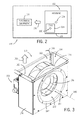
- FIG. 2 is a schematic of an electrical equipment system, which may include a blower or fan having an eccentric housing, in accordance with an embodiment of the present invention
- FIG. 3 is a perspective view of a fan having an eccentric housing, in accordance with an embodiment of the present invention.
- FIG. 4 is a perspective view of a fan having an eccentric housing, in accordance with an embodiment of the present invention.
- FIG. 5 is an orthographic projection of a fan having an eccentric housing, in accordance with an embodiment of the present invention.
- FIG. 6 is a perspective view of a fan and an inlet ring, in accordance with an embodiment of the present invention.
- FIG. 7 is a table illustrating the effect of grid size on volumetric flow at an inlet of a fan, in accordance with an embodiment of the present invention.
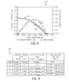
- FIG. 8 is graph illustrating a comparison between simulated results of a modeled fan and data provided by a manufacturer of the fan, in accordance with an embodiment of the present invention
- FIG. 9 is a table of various data points used to determine a corrected fan speed of a fan model, in accordance with an embodiment of the present invention.
- FIG. 10 is a graph illustrating a comparison between fan manufacturer data and a corrected fan speed, in accordance with an embodiment of the present invention.
- FIG. 11 is an orthographic projection of a parametric model of a fan having an eccentric housing, in accordance with an embodiment of the present invention.
- FIG. 12 is a table having ranges of various geometric variables used for a parametric modeling of an eccentric housing, in accordance with an embodiment of the present invention.
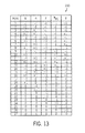
- FIG. 13 is a table listing runs or iterations computed with a computational fluid dynamics tool, in accordance with an embodiment of the present invention.
- FIG. 14 is a table listing parameters derived to predict localized flow coefficients of an eccentric housing, in accordance with an embodiment of the present invention.
- FIG. 15 is a table including values of various geometric variables used to define eccentric placement of a fan within a fan housing, in accordance with an embodiment of the present invention.
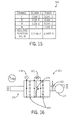
- FIG. 16 is a schematic illustrating a flow bench for testing a fan housing, in accordance with an embodiment of the present invention.
- FIG. 17 is a graph illustrating test results for a fan housing tested using the flow bench of FIG. 16 , in accordance with an embodiment of the present invention.
- FIG. 18 is a graph illustrating test results for a fan housing tested using the flow bench of FIG. 16 , in accordance with an embodiment of the present invention.
- FIG. 19 is a graph illustrating test results for a fan housing tested using the flow bench of FIG. 16 , in accordance with an embodiment of the present invention.
- FIG. 20 is a graph illustrating test results for a fan housing tested using the flow bench of FIG. 16 , in accordance with an embodiment of the present invention.
- FIG. 21 is a graph illustrating a design curve for an eccentric fan housing, in accordance with an embodiment of the present invention.
- FIG. 22 is a graph illustrating a design curve for an eccentric fan housing, in accordance with an embodiment of the present invention.
- Embodiments of the present disclosure are directed towards a fan or blower housing with a fan disposed eccentrically within the housing.
- the geometric center or axis of rotation of the fan is not concentric with a geometric center of the housing.
- the housing may have a rectangular or square configuration.
- the eccentric or offset placement of the fan within the housing may be uniquely customized or optimized based upon various variables such as fan size, fan capacity, housing size, operating pressure, and so forth.
- FIG. 1 is a perspective view of a motor drive 100, which may include a blower or fan with an eccentric housing.
- the motor drive 100 may be a PowerFlex drive manufactured by Rockwell Automation of Milwaukee, Wisconsin.
- the motor drive 100 may be representative of other electronic devices employing an air cooling system in accordance with present techniques.
- the motor drive 100 includes a housing 102 having cooling vents 104 on one or more sides of the drive 100.
- the motor drive 100 may include a human-machine interface (HMI) 106.
- the HMI 106 may include a display 108, such as an LCD or other display and a keypad 110 allowing input by a user. Additionally, the HMI 106 may be removable and dockable in a receptacle in the housing 102.
- the motor drive 100 may include a thermal management system 112 including a blower or fan with an eccentric housing.
- the blower or fan e.g., a centrifugal fan
- the blower or fan may be configured to provide a cooling air flow into the motor drive 100. That is, the blower or fan may force a cooling air flow across electrical equipment within the motor drive 100.
- the motor drive 100 may include motor starters, overload relays, circuit breakers, and solid-state motor control devices, such as variable frequency drives, programmable logic controllers, power regeneration circuitry, and so forth.
- such electrical equipment may generate heat during operation, thereby reducing efficiency of the electrical equipment.
- the temperature of such electrical equipment may be controlled and/or lowered by the cooling air flow generated by a fan or blower.
- the fan or blower may be disposed within an eccentric housing.
- the fan or blower may be positioned in an offset or off-center location relative to the housing.
- the housing generally may be rectangular (e.g., square) to facilitate consistent installation in electrical devices and to conserve limited available space within the electrical devices. It is now recognized that by eccentrically positioning the blower or fan within the housing, the shape and quantity of the cooling air flow exiting fan or blower may be adjusted. In this manner, the efficiency of the thermal management system 112 (i.e., the fan or blower) may be improved. For example, the shape, pressure, and/or flow rate of the cooling air flow may be modified without adjusting the size of the housing.
- the noise performance and energy use of the blower or fan may be improved.
- the off-center or eccentric placement of the blower or fan may be optimized for specific applications or operating conditions.
- the fan or blower may be modeled using computational fluid dynamics software, and the eccentric placement of the fan or blower within the housing may be customized or calculated (e.g., using a design of experiments approach) to achieve a desired fan or blower performance.
- FIG. 2 is a schematic of an electrical equipment system 120 (e.g., a motor drive), which may include the thermal management system 112. While embodiments of the thermal management system 112 described above are discussed in the context of the motor drive 100, the thermal management system 112 having a fan or blower with an eccentric housing may be used in other systems having electrical equipment.
- the electrical equipment system 120 illustrated in FIG. 2 may be any of a variety of systems having electrical equipment 122.
- the electrical equipment system 120 may be a personal computer, a router or switch, a transformer, a manufacturing plant, a household appliance, an automobile, or any other system having electrical equipment 122.
- the thermal management system 112 includes a fan 124 disposed within a housing 126. More specifically, as discussed in detail below, the fan 124 is disposed within the housing 126 such that the fan 124 has an eccentric, offset, or off-center placement relative to a geometric center 128 (e.g., center point) of the housing 126. That is, a geometric center 130 (e.g., center point) of the fan 124 is not concentric with the geometric center 128 of the housing 126. As shown, the thermal management system 112 generates a cooling air flow 132, which may pass towards, over, or across the electrical equipment 122, thereby reducing the temperature of the electrical equipment 122. Due to the eccentric placement of the fan 124 within the housing 126, various properties of the cooling air flow 132 may be adjusted, and efficiency of the thermal management system 112 and the electrical equipment 122 may be improved, as discussed below.
- a geometric center 128 e.g., center point
- the thermal management system 112 generates a cooling air flow 132, which
- FIG. 3 is a perspective view of the thermal management system 112, illustrating the fan 124 disposed eccentrically within the housing 126. That is, the geometric center 130 of the fan 124 (e.g., an axis of rotation 140 of the fan 124) is not concentric with the geometric center 128 of the housing 126.
- the housing 126 which may be formed from sheet metal or other material, has a rectangular configuration. That is, front and rear faces of the housing 126 are substantially rectangular.
- the housing 126 may have a rectangular prism configuration, and/or an interior of the housing 126 may have a substantially cubic volume.
- other embodiments of the housing 126 may have other configurations.
- the fan 124 in the illustrated embodiment is mounted within the housing 126 with an inlet ring 142 and is configured to generate an air flow 150, which exits the housing 126 at an approximately 90 degree angle relative to an air inlet 152 of the fan 124. More particularly, air 154 enters the housing 126 through the air inlet 152, and the fan 124, which is driven in a clockwise direction 156 by a motor 158, generates the air flow 150, which exits through an open top 160 of the housing 126. Due to the eccentric mounting of the fan 124 within the housing 126, a high pressure zone 162 within the housing 126 may be larger than a low pressure zone 164 within the housing.
- the flow rate of the air flow 150 of the fan 124 and the housing 126 may be improved, thereby improving the efficiency of the fan 124 and the housing 126. Additionally, the decrease in size of the low pressure zone 164 may help reduce portions of the air flow 150, represented by arrow 166, from re-entering the housing 126.
- FIG. 4 is a perspective view of the thermal management system 112, illustrating the fan 124 disposed eccentrically within the housing 126. More particularly, FIG. 4 provides a perspective view of the thermal management system 112 with the motor 158 positioned in front. As a result, FIG. 4 clearly illustrates that the motor 158 is also disposed eccentrically with respect to the housing 126. In other words, a geometric center or axis of rotation of the motor 158 is offset from the geometric center 128 of the housing 126.
- the motor 158 may be an electric motor, such as a brushless DC motor, however, other types of motors 158 may be used to power the fan 124.
- FIG. 5 is an orthographic projection of the fan 124 disposed eccentrically within the housing 126.
- the housing 126 has a rectangular configuration. More specifically, the illustrated housing 126 has a height 180, a length 182, and a depth 184. Additionally, the fan 124 has a diameter 186.
- the diameter 186 may be approximately 100 to 500 mm, 150 to 450 mm, 200 to 400 mm, or 250 to 350 mm.
- the fan 124 has an offset or off-center placement within the housing 126. That is, while the fan 124 itself is generally uniform in shape, the geometric center 130 of the fan 124 is not concentric with the geometric center 128 of the housing 126.
- the eccentricity of the fan 124 within the housing 126 may be described with reference to various geometric variables.
- the location of the fan 124 within the housing 126 may be described with respect to various distances from the fan 124 to the housing 126.
- an outer circumference 188 of the fan 124 is approximately a distance 190 from a base 192 of the housing 126. That is, the fan 124 is positioned the distance 190 above the base 192 of the housing 126. Consequently, the outer circumference 188 of the fan 124 is located a distance 194 from the top 160 of the housing 126.
- the outer circumference 188 of the fan 124 is positioned a distance 196 from a left wall 198 of the housing 126 and a distance 200 from a right wall of the housing 126.
- the distances 196 and 200 may not be equal, thereby positioning the fan 124 in an off-center or offset location relative to the housing 126.
- the distances 190, 194, 196, and 200 may be used to define the position of the fan 124 within the housing 126, at least with respect to a front face 204 and a rear face 206 of the housing 126.
- the position of the fan 124 within the housing 126 may be at least partially expressed in terms of a distance 208 the motor 158 is positioned from the rear face 206 of the housing 126. That is, the distance 208 is the distance from a front facing surface 210 of the motor to the housing wall forming the rear face 206 (i.e., the face opposite the front face 204 or air inlet 152).
- the discussed geometric variables may be customized or optimized to achieve desired or target characteristics of the air flow 150 generated by the fan 124 and the housing 126.
- the geometric variables discussed above may be optimized based upon factors such as a size or capacity of the fan 124 and/or size constraints of the housing 126 (e.g., the height 180, the length 182, and the depth 184 of the housing 126).
- a ratio of the distance 196 to the diameter 186 of the fan 124 may be approximately 0.10 to 0.30.
- a ratio of the distance 190 to the diameter 186 of the fan 124 may be approximately 0.05 to 0.30.
- a ratio of the distance 200 to the diameter 186 of the fan 124 may be approximately 0.05 to 0.20.
- a ratio of the distance 196 to the distance 190 may be approximately 2.50 to 0.50.
- a ratio of the distance 196 to the distance 200 may be approximately 2.50 to 1.50, and a ratio of the distance 190 to the distance 200 may be approximately 0.50 to 2.00.
- the geometric variables may be optimized using parametric modeling (e.g., modeling of the fan 124 and/or the housing 126) and statistical methods to achieve an improved air flow 150.
- an ambient or operating pressure of the environment having the housing 126 and fan 124, indicated by arrows 212, may be considered in optimizing the eccentricity of the fan 124 within the housing 126.
- the experimental data reproduced below indicates that the eccentric positioning of the fan 124 within the housing 126 may contribute to improved flow rates, pressure, efficiencies, and so forth, of the air flow 150.
- the improved air flow 150 may then enable improved cooling of electrical equipment 122 within the electrical equipment system 120 (e.g., the motor drive 100), thereby improving performance and efficiency of the electrical equipment system 120.
- Q volumetric flow
- ⁇ rotational speed of the fan 124
- P pressure
- ⁇ density of air
- D the diameter 186 of the fan 124.
- ANSYS Icepak 13 The computational fluid dynamics (CFD) software used in the present experiments was ANSYS Icepak 13.
- ANSYS Icepak 13 has built-in objects that represent simplified impellers and centrifugal fans (e.g., fan 124). These built-in objects may be used to simulate flow in various applications. Additionally, a Moving Reference Frame (MRF) technique was used to account for effects of blade geometry and swirl.
- MRF Moving Reference Frame
- FIG. 6 is a perspective view of the fan 124 and the inlet ring 142 imported into ANYSS Icepak 13.
- the models of the fan 124 and the inlet ring 142 were placed in a box 220 where the boundaries were located one diameter from the fan 124. As shown, all sides 222 of the box 220, except for an inlet side 224 were open. In this way, the performance of the fan 124 without the housing 126 could be simulated.
- the MRF fluid cylinder was defined to be 2% larger than the diameter 186 of the fan 124, so as to enclose the entire moving portion of the fan 124. Additionally, the operational fan 124 speed was assigned to the MRF fluid region.
- a multi-level meshing technique was used along with an automated hex-dominated mesher to capture detailed interactions between blades 226 of the fan 124 and the MRF fluid.
- the blade 226 geometry was assigned a value of two, while the remaining geometry was assigned a value of one.
- the model was run at a temperature of 20°C and an air density of 1.2 kg/m 3 using first-order discretization methods for continuity, momentum, and turbulence equations. Model convergence was achieved when the maximum normalized residual was less than 1 x 10 -4 .
- FIG. 7 is a table 240 illustrating the effect of grid size on volumetric flow at the inlet 152 of the fan 124 with the normalized pressure coefficient ( ⁇ ) of 0.058.
- FIG. 7 includes maximum grid size, size ration, mesh count, and flow coefficient ( ⁇ ) for coarse, medium, and fine grids.
- the grid convergence index was calculated to be 0.011% for the flow coefficient ( ⁇ ) at the inlet 152 of the fan 124.
- the finest grid e.g., "Fine", shown in table 240 was used.
- FIG. 8 is a graph 250 illustrating a comparison between the Icepak MRF simulation results of the fan 124, indicated by reference numeral 252, and fan 124 data provided by the fan 124 manufacturer, indicated by reference numeral 254. As shown, the fan 124 performance predicted by the Icepak MRF simulation (e.g., line 252) followed, but consistently under-predicted, the performance measured by the manufacturer (e.g., lines 254).
- FIG. 9 is a table 260 of various data points used to determine a corrected fan speed of the fan 124 model.
- the approach used to tune the model of the fan 124 was to adjust the fan 124 speed used in the model (e.g., ⁇ model ) to minimize the error between the predicted fan 124 curve (e.g., line 252 in the graph 250 of FIG. 8 ) and the manufacturer's data curve (e.g., line 254 in the graph 250 of FIG. 8 ).
- the expected fan 124 pressure for teach data point at the same corrected Icepak volumetric flow was calculated using Eqn. (4) above.
- the tuned fan speed ⁇ model for the Icepak model was found to be 2.4% higher than the actual operating speed.
- FIG. 10 shows a graph 270 illustrating a comparison between the manufacturer data, indicated by reference numeral 272, and the corrected or tuned fan speed, indicated by reference numeral 274. More specifically, over the pressure coefficient range of 0.032 to 0.069, the graph 270 shows that the manufacturer data (e.g., line 272) and the corrected model fan speed (e.g., line 274) are in agreement. In other words, the fan 124 performance predicted by the Icepak model approximately matches the manufacturer data after a 2.4% speed increase in the Icepak model.
- certain disclosed embodiments are directed towards fan housings 126 with rectangular or square configurations or shapes. Additionally, certain embodiments of the housing 126 output an air flow (e.g., air flow 150) at essentially a 90 degree angle from a central axis of an inlet (e.g., inlet 152) of the housing 126. In other words, air enters the fan 124 on one side (e.g., inlet side 224) and exits on a side 90 degrees from the inlet. Additionally, as discussed above, the eccentric placement of the fan 124 within the housing 126 may be defined with respect to various geometric variables. For example, FIG.
- FIG. 11 is an orthographic projection of a parametric model of the housing 126, illustrating various input factors (e.g., geometric variables) that define the eccentricity of the fan 124.
- the orthographic projection shown in FIG. 11 is similar to the orthographic projection shown in FIG. 5 .
- the orthographic projection shown in FIG. 11 includes the experimental variables used in the discussion below.
- the four geometric variables that were selected for the rectangular fan housing 126 that defined the eccentric placement of the fan having a diameter D within the housing 126 were each of the distances from the front (F), bottom (B), and rear (R) walls to the fan 124 and the distance (M) from the motor (e.g., motor 158) to the wall opposite the fan inlet (e.g., inlet 152).
- a fifth variable, the pressure coefficient applied at the blower housing outlet ( ⁇ BC ) was selected so that the fan performance curve could be extracted over the expected pressure coefficient operating region of 0.032 and 0.069. Furthermore, as shown in FIG.
- FIG. 12 illustrates a table 280 which includes ranges, expressed in terms of the diameter D of the fan 124, of the input factors (e.g., geometric variables) used for the parametric modeling of the fan housing 126. Specifically, FIG. 12 includes minimum and maximum values for variables F, R, B, M, and ⁇ , which are all illustrated in FIG. 11 and described in table 280.
- Design of Experiments is a statistical method where a set of input factors (Xs) are varied in a controlled manner in order to measure their effects on one or more response variables (Ys).
- Xs input factors
- Ys response variables
- the advantage of using a DoE approach is that the relationships among the input factors and response variables can be extracted in a fewer number of experiments. Additionally, the relationships among the input factors and response variables may be expressed in an empirical model that contains first-order and second-order terms.
- a five-factor, 2-level, half-factorial design was used. This design required multiple runs or iterations in Icepak, which are listed in table 290 shown in FIG. 13 .
- the -1 value indicates the minimum value and the +1 value indicates the maximum value for each variable listed in table 280 of FIG. 12 .
- the flow coefficient responses were expected to have strong second-order effects, so additional face-centered points (e.g., runs 17-26 in table 290) were added, as well as a center point (e.g., run 27 in table 290).
- a value of zero indicates a mid-point value between the minimum (-1) and maximum (+1) values listed in table 280.
- the model parameters ( a n ) in Eqn. (8) below were calculated using a backward linear regression algorithm where a term was removed if the t-statistic for that term was greater than 0.05 (indicating that there is a 95% probability that the term is zero). The backward regression algorithm starts with removing any insignificant second-order terms, followed by a two-way interaction, and linear terms.
- ⁇ 1 ⁇ ⁇ 2 ⁇ ⁇ 3 ⁇ ⁇ 4 ⁇ ⁇ 5 ⁇ ⁇ 6 a 0 + a 1 ⁇ M + a 2 ⁇ R + a 3 ⁇ F + a 4 ⁇ ⁇ BC + a 5 ⁇ B + a 12 ⁇ M ⁇ R + a 13 ⁇ M ⁇ F + a 14 ⁇ M ⁇ ⁇ BC + a 15 ⁇ M ⁇ B + a 23 ⁇ R ⁇ F + a 24 ⁇ R ⁇ ⁇ BC + a 25 ⁇ R ⁇ B + a 24 ⁇ F ⁇ ⁇ BC + a 35 ⁇ F ⁇ B + a 45 ⁇ ⁇ BC ⁇ B + a 11 ⁇ M 2 + a 22 ⁇ R 2 + a 33 .
- the first housing 126 design attempted to maximize the power coefficient over the expected pressure coefficient range of 0.032 to 0.069.
- F + R D ⁇ 0.248 M 0 B D ⁇ 0.08
- the genetic algorithm was run with a population of 200 individuals until there was no change in objective function for at least 20 generations.
- the average power coefficient for Design 1 is 17% lower than the average power coefficient for Design 2, due to more stringent geometric constraints which limit the flow (e.g., air flow 150).
- the table 300 includes values, expressed in terms of the diameter D of the fan 124, of the various geometric variables used to define the eccentric placement of the fan 124 within the housing 126.
- FIG. 16 is a schematic illustrating a flow bench 320 that was designed and built to allow for testing the housing 126 according to ANSI/AMCA 210-07 standards.
- the flow bench 320 was capable of measuring volumetric flow rates up to 1100 ft 3 /min and pressure up to 3 inches of water.
- the volumetric flow through the tested device e.g., the housing 126) was obtained by first measuring a pressure drop 322 across precision flow nozzles 324 installed in parallel.
- the precision nozzles 324 may be 1, 2, 3, or 4 inch flow nozzles 324, and the flow nozzles 324 may be manufactured to the AMCA 210-07 standard.
- Settling screens 326 upstream and downstream of the flow nozzles 324 were incorporated to smooth out the flow field.
- a static pressure for the housing 126 was measured using a manometer 328, with one end open to atmosphere. The pressure measurements were obtained by average four pressure taps located 90 degrees apart, perpendicular to the flow direction. Fan performance curves, discussed below, were obtained by adjusting the flow rate with an adjustable blast gate 330 while holding the flow bench blower (e.g., fan 124) constant.
- FIGS. 17-20 are graphs illustrating the results of the experiments described above. That is, the graphs in FIGS. 17-20 show the housing 126 performance on the flow bench 320 for Designs 1 and 2 of the housing 126 described above.
- FIG. 17 is a graph 350 of the flow bench 320 test results for the first, second, and third samples of Design 1 of the housing 126.
- the graph 350 shows flow and pressure coefficient performance for Design 1 of the housing 126 as predicted by Icepak and the Design of Experiments calculations compared to the measured performance (e.g., using the flow bench 320) for the three samples of Design 1 of the housing 126.
- the Design of Experiments model predicted the flow coefficient with a maximum error of 4.3%, it did not completely capture the curvature.
- the Icepak model that was run for Design 1 of the housing 126 correctly predicted the flow coefficients and agreed with the measured samples with a maximum error of 1.6%.
- FIG. 18 is a graph 360 of the flow bench 320 test results for the first, second, and third samples of Design 1 of the housing 126, illustrating power coefficient performance (e.g., calculated from flow and pressure measurements) for Design 1 of the fan housing 126 compared with the performance predicted by Icepak and the Design of Experiments calculations.
- the Design of Experiments predicted the power coefficient with a maximum error of 6.3% over the pressure coefficient range of 0.032 to 0.069
- the Icepak model predicted the power coefficient with a maximum error of 3.8%.
- the Icepak model accurately captured the power coefficient behavior as it varied with flow coefficient.
- FIG. 19 is a graph 370 of the flow bench 320 test results for the first, second, and third samples of Design 2 of the housing 126.
- the graph 370 shows flow and pressure coefficient performance for Design 2 of the housing 126 as predicted by Icepak and the Design of Experiments calculations compared to the measured performance (e.g., using the flow bench 320) for the three samples of Design 2 of the housing 126.
- the Design of Experiments model predicted the flow coefficient with a maximum error of 6.0%.
- the maximum error for the Icepack prediction for the flow coefficient was 7.1%.
- FIG. 20 is a graph 380 of the flow bench 320 test results for the first, second, and third samples of Design 2 of the housing 126, illustrating power coefficient performance (e.g., calculated from flow and pressure measurements) for Design 2 of the fan housing 126 compared with the performance predicted by Icepak and the Design of Experiments calculations.
- the Design of Experiments model predicted the power coefficient with a maximum error of 3.5% over the pressure coefficient range of 0.032 to 0.069, while the Icepak prediction for power coefficient has a maximum error of 5.6%.
- one advantage of having performed a Design of Experiments study on the housing 126 design is that the flow, pressure, and power coefficient behavior may be captured over a wide geometry for the housing 126 and pressure coefficient range for the fan 124.
- FIGS. 21 and 22 illustrate the design curves generated using the process described above.
- the curves in graphs 400 and 410 can be used to help understand housing 126 geometric effects on fan 124 performance.
- the power coefficient curves in graph 410 indicate the d h /D ratio has a greater effect on power coefficient as the pressure coefficient value increases.
- Embodiments of the present disclosure are directed towards a fan or blower housing with a fan disposed eccentrically within the housing. Indeed, the geometric center or axis of rotation of the symmetrical fan is not concentric with a geometric center of the housing.
- the housing may have a rectangular or square configuration. Additionally, the eccentric or offset placement of the fan within the housing may be customized or optimized based upon variables such as fan size, fan capacity, housing size, operating pressure, and so forth.
Landscapes
- Engineering & Computer Science (AREA)
- Microelectronics & Electronic Packaging (AREA)
- Physics & Mathematics (AREA)
- Thermal Sciences (AREA)
- Structures Of Non-Positive Displacement Pumps (AREA)
- Cooling Or The Like Of Electrical Apparatus (AREA)
Applications Claiming Priority (1)
| Application Number | Priority Date | Filing Date | Title |
|---|---|---|---|
| US13/436,551 US20130260664A1 (en) | 2012-03-30 | 2012-03-30 | Eccentric fan housing |
Publications (3)
| Publication Number | Publication Date |
|---|---|
| EP2645840A2 true EP2645840A2 (de) | 2013-10-02 |
| EP2645840A3 EP2645840A3 (de) | 2018-03-21 |
| EP2645840B1 EP2645840B1 (de) | 2022-08-17 |
Family
ID=48190699
Family Applications (1)
| Application Number | Title | Priority Date | Filing Date |
|---|---|---|---|
| EP13161920.7A Active EP2645840B1 (de) | 2012-03-30 | 2013-04-02 | Exzentrisches Lüftergehäuse |
Country Status (5)
| Country | Link |
|---|---|
| US (1) | US20130260664A1 (de) |
| EP (1) | EP2645840B1 (de) |
| CN (1) | CN103557183B (de) |
| BR (1) | BR102013007545A2 (de) |
| CA (1) | CA2810656A1 (de) |
Families Citing this family (8)
| Publication number | Priority date | Publication date | Assignee | Title |
|---|---|---|---|---|
| DE102012016606A1 (de) * | 2012-08-23 | 2014-02-27 | Robert Bosch Gmbh | Verfahren zur Regelung einer Heizeinrichtung und Heizeinrichtung |
| US9322127B2 (en) * | 2013-05-22 | 2016-04-26 | Whirlpool Corporation | Method of operating a home appliance |
| US20150195923A1 (en) * | 2014-01-03 | 2015-07-09 | Passam Yusef Yusef | Ergonomic Computer Design |
| US9869722B1 (en) | 2016-09-22 | 2018-01-16 | Rockwell Automation Technologies, Inc. | Method and apparatus for electrical component life estimation |
| US11236762B2 (en) * | 2019-04-26 | 2022-02-01 | Johnson Controls Technology Company | Variable geometry of a housing for a blower assembly |
| US11476792B2 (en) | 2020-06-16 | 2022-10-18 | Rockwell Automation Technologies, Inc. | Method and apparatus for electrical component life estimation with corrosion compensation |
| CN116241943B (zh) * | 2021-12-08 | 2025-09-05 | 青岛海尔空调电子有限公司 | 空调室内机 |
| CN115179815A (zh) * | 2022-03-29 | 2022-10-14 | 中国第一汽车股份有限公司 | 一种动力电池温度控制方法、系统、终端及存储介质 |
Family Cites Families (14)
| Publication number | Priority date | Publication date | Assignee | Title |
|---|---|---|---|---|
| GB1007068A (en) * | 1963-10-29 | 1965-10-13 | Brightside Heating And Enginee | Improvements relating to centrifugal fans |
| DE1904311A1 (de) * | 1968-01-31 | 1969-09-04 | Svenska Flaektfabriken Ab | Schleudergeblaese |
| DE2139036A1 (de) * | 1971-08-04 | 1973-02-15 | Papst Motoren Kg | Luefter, insbesondere tischluefter |
| US4128364A (en) * | 1972-11-23 | 1978-12-05 | Papst-Motoren Kg | Radial flow fan with motor cooling and resilient support of rotor shaft |
| US4073597A (en) * | 1977-01-28 | 1978-02-14 | The Celotex Corporation | Fan housing assembly |
| TW581158U (en) * | 2003-03-31 | 2004-03-21 | Delta Electronics Inc | Side-blown fan |
| TWM242763U (en) * | 2003-06-17 | 2004-09-01 | Wistron Corp | System structure and fan module thereof |
| US6884033B2 (en) * | 2003-09-29 | 2005-04-26 | Cheng Home Electronics Co., Ltd. | Volute inlet of fan |
| US6979169B2 (en) * | 2003-11-21 | 2005-12-27 | Broan-Nutone Llc | Modular ventilating exhaust fan assembly and method |
| EP1657451A1 (de) * | 2004-11-12 | 2006-05-17 | Hans Östberg | Kanalgebläse |
| US7443670B2 (en) * | 2005-01-07 | 2008-10-28 | Intel Corporation | Systems for improved blower fans |
| TWI330223B (en) * | 2005-01-27 | 2010-09-11 | Delta Electronics Inc | Blower |
| JP4240061B2 (ja) * | 2006-05-29 | 2009-03-18 | ソニー株式会社 | ファンモータおよび電子機器 |
| US8325479B2 (en) * | 2010-07-16 | 2012-12-04 | Rockwell Automation Technologies, Inc. | Motor drive cooling duct system and method |
-
2012
- 2012-03-30 US US13/436,551 patent/US20130260664A1/en not_active Abandoned
-
2013
- 2013-03-27 CA CA2810656A patent/CA2810656A1/en not_active Abandoned
- 2013-03-28 BR BR102013007545A patent/BR102013007545A2/pt not_active Application Discontinuation
- 2013-04-01 CN CN201310133102.6A patent/CN103557183B/zh not_active Expired - Fee Related
- 2013-04-02 EP EP13161920.7A patent/EP2645840B1/de active Active
Non-Patent Citations (1)
| Title |
|---|
| None |
Also Published As
| Publication number | Publication date |
|---|---|
| CN103557183B (zh) | 2016-12-28 |
| EP2645840B1 (de) | 2022-08-17 |
| CN103557183A (zh) | 2014-02-05 |
| US20130260664A1 (en) | 2013-10-03 |
| BR102013007545A2 (pt) | 2015-10-06 |
| CA2810656A1 (en) | 2013-09-30 |
| EP2645840A3 (de) | 2018-03-21 |
Similar Documents
| Publication | Publication Date | Title |
|---|---|---|
| EP2645840B1 (de) | Exzentrisches Lüftergehäuse | |
| Huang et al. | Performance analysis and optimized design of backward-curved airfoil centrifugal blowers | |
| JP2017062676A (ja) | 軸流ファンの通風解析方法,通風解析装置及び通風解析プログラム | |
| Kim et al. | Development of a low-noise cooling fan for an alternator using numerical and doe methods | |
| Morris et al. | Driving energy efficiency with design optimization of a centrifugal fan housing system for variable frequency drives | |
| Lee et al. | Reduction of flow-induced noise in a household air purifier | |
| Mehravaran et al. | Optimizing the Geometry of Fan-Shroud Assembly Using CFD | |
| Srinivas et al. | Numerical simulation of axial flow fan using Gambit and Fluent | |
| Hermez et al. | Comparison of inlet curved disk arrangements for suppression of recirculation in centrifugal pump impellers | |
| Park et al. | Aerodynamic Characteristics of a Cooling Fan in a Low-voltage Electric Motor | |
| Charapale et al. | Prediction of flow in the industrial blower using computational fluid dynamics | |
| Stoyanov et al. | Numerical study of radial high-pressure blower with frequency converter | |
| Kim et al. | Performance of a cross-flow fan with various shapes of a rearguider and an exit duct | |
| JP2017101590A (ja) | 送風機の設計方法 | |
| Fukayama et al. | An adaptive state estimator for pulverizer control using moments of particle size distribution | |
| Frank et al. | Design improvements of sirocco type fans by means of computational fluid dynamics and stereoscopic particle image velocimetry | |
| Younsi et al. | 2D and 3D unsteady flow in squirrel-cage centrifugal fan and aeroacoustic behavior | |
| Ellorde et al. | Numerical Investigation on the Effects of Varying Centrifugal Impeller Blade Number on Pump Head and Efficiency Using ANSYS 2020 R2 | |
| Syka et al. | Hub and shroud fillets influence on the radial compressor stage efficiency | |
| Hur et al. | A numerical study on the performance of a magnesium-based automotive cooling fan with bead structure | |
| Amjadimanesh et al. | Effect of blade type on a 3D FC centrifugal fan | |
| Vahdati et al. | Core-compressor rotating stall simulation with a multi-bladerow model | |
| Lee et al. | Development of high-efficiency axial flow fan using the FANDAS code | |
| Heo et al. | Aerodynamic Optimization of a Backward-Curved Blades Centrifugal Fan Using Total FAN-Turbo | |
| Hashim et al. | An investigation into performance characteristics of an axial flow fan using CFD for electronic devices |
Legal Events
| Date | Code | Title | Description |
|---|---|---|---|
| PUAI | Public reference made under article 153(3) epc to a published international application that has entered the european phase |
Free format text: ORIGINAL CODE: 0009012 |
|
| AK | Designated contracting states |
Kind code of ref document: A2 Designated state(s): AL AT BE BG CH CY CZ DE DK EE ES FI FR GB GR HR HU IE IS IT LI LT LU LV MC MK MT NL NO PL PT RO RS SE SI SK SM TR |
|
| AX | Request for extension of the european patent |
Extension state: BA ME |
|
| PUAL | Search report despatched |
Free format text: ORIGINAL CODE: 0009013 |
|
| AK | Designated contracting states |
Kind code of ref document: A3 Designated state(s): AL AT BE BG CH CY CZ DE DK EE ES FI FR GB GR HR HU IE IS IT LI LT LU LV MC MK MT NL NO PL PT RO RS SE SI SK SM TR |
|
| AX | Request for extension of the european patent |
Extension state: BA ME |
|
| RIC1 | Information provided on ipc code assigned before grant |
Ipc: H05K 7/20 20060101AFI20180214BHEP |
|
| STAA | Information on the status of an ep patent application or granted ep patent |
Free format text: STATUS: REQUEST FOR EXAMINATION WAS MADE |
|
| 17P | Request for examination filed |
Effective date: 20180904 |
|
| RBV | Designated contracting states (corrected) |
Designated state(s): AL AT BE BG CH CY CZ DE DK EE ES FI FR GB GR HR HU IE IS IT LI LT LU LV MC MK MT NL NO PL PT RO RS SE SI SK SM TR |
|
| STAA | Information on the status of an ep patent application or granted ep patent |
Free format text: STATUS: EXAMINATION IS IN PROGRESS |
|
| 17Q | First examination report despatched |
Effective date: 20200227 |
|
| GRAP | Despatch of communication of intention to grant a patent |
Free format text: ORIGINAL CODE: EPIDOSNIGR1 |
|
| STAA | Information on the status of an ep patent application or granted ep patent |
Free format text: STATUS: GRANT OF PATENT IS INTENDED |
|
| INTG | Intention to grant announced |
Effective date: 20220110 |
|
| GRAJ | Information related to disapproval of communication of intention to grant by the applicant or resumption of examination proceedings by the epo deleted |
Free format text: ORIGINAL CODE: EPIDOSDIGR1 |
|
| STAA | Information on the status of an ep patent application or granted ep patent |
Free format text: STATUS: EXAMINATION IS IN PROGRESS |
|
| INTC | Intention to grant announced (deleted) | ||
| GRAP | Despatch of communication of intention to grant a patent |
Free format text: ORIGINAL CODE: EPIDOSNIGR1 |
|
| STAA | Information on the status of an ep patent application or granted ep patent |
Free format text: STATUS: GRANT OF PATENT IS INTENDED |
|
| INTG | Intention to grant announced |
Effective date: 20220523 |
|
| GRAS | Grant fee paid |
Free format text: ORIGINAL CODE: EPIDOSNIGR3 |
|
| GRAA | (expected) grant |
Free format text: ORIGINAL CODE: 0009210 |
|
| STAA | Information on the status of an ep patent application or granted ep patent |
Free format text: STATUS: THE PATENT HAS BEEN GRANTED |
|
| AK | Designated contracting states |
Kind code of ref document: B1 Designated state(s): AL AT BE BG CH CY CZ DE DK EE ES FI FR GB GR HR HU IE IS IT LI LT LU LV MC MK MT NL NO PL PT RO RS SE SI SK SM TR |
|
| REG | Reference to a national code |
Ref country code: GB Ref legal event code: FG4D |
|
| REG | Reference to a national code |
Ref country code: CH Ref legal event code: EP |
|
| REG | Reference to a national code |
Ref country code: DE Ref legal event code: R096 Ref document number: 602013082320 Country of ref document: DE |
|
| REG | Reference to a national code |
Ref country code: IE Ref legal event code: FG4D |
|
| REG | Reference to a national code |
Ref country code: AT Ref legal event code: REF Ref document number: 1513018 Country of ref document: AT Kind code of ref document: T Effective date: 20220915 |
|
| REG | Reference to a national code |
Ref country code: NL Ref legal event code: MP Effective date: 20220817 |
|
| REG | Reference to a national code |
Ref country code: LT Ref legal event code: MG9D |
|
| PG25 | Lapsed in a contracting state [announced via postgrant information from national office to epo] |
Ref country code: SE Free format text: LAPSE BECAUSE OF FAILURE TO SUBMIT A TRANSLATION OF THE DESCRIPTION OR TO PAY THE FEE WITHIN THE PRESCRIBED TIME-LIMIT Effective date: 20220817 Ref country code: RS Free format text: LAPSE BECAUSE OF FAILURE TO SUBMIT A TRANSLATION OF THE DESCRIPTION OR TO PAY THE FEE WITHIN THE PRESCRIBED TIME-LIMIT Effective date: 20220817 Ref country code: PT Free format text: LAPSE BECAUSE OF FAILURE TO SUBMIT A TRANSLATION OF THE DESCRIPTION OR TO PAY THE FEE WITHIN THE PRESCRIBED TIME-LIMIT Effective date: 20221219 Ref country code: NO Free format text: LAPSE BECAUSE OF FAILURE TO SUBMIT A TRANSLATION OF THE DESCRIPTION OR TO PAY THE FEE WITHIN THE PRESCRIBED TIME-LIMIT Effective date: 20221117 Ref country code: NL Free format text: LAPSE BECAUSE OF FAILURE TO SUBMIT A TRANSLATION OF THE DESCRIPTION OR TO PAY THE FEE WITHIN THE PRESCRIBED TIME-LIMIT Effective date: 20220817 Ref country code: LV Free format text: LAPSE BECAUSE OF FAILURE TO SUBMIT A TRANSLATION OF THE DESCRIPTION OR TO PAY THE FEE WITHIN THE PRESCRIBED TIME-LIMIT Effective date: 20220817 Ref country code: LT Free format text: LAPSE BECAUSE OF FAILURE TO SUBMIT A TRANSLATION OF THE DESCRIPTION OR TO PAY THE FEE WITHIN THE PRESCRIBED TIME-LIMIT Effective date: 20220817 Ref country code: FI Free format text: LAPSE BECAUSE OF FAILURE TO SUBMIT A TRANSLATION OF THE DESCRIPTION OR TO PAY THE FEE WITHIN THE PRESCRIBED TIME-LIMIT Effective date: 20220817 Ref country code: ES Free format text: LAPSE BECAUSE OF FAILURE TO SUBMIT A TRANSLATION OF THE DESCRIPTION OR TO PAY THE FEE WITHIN THE PRESCRIBED TIME-LIMIT Effective date: 20220817 |
|
| REG | Reference to a national code |
Ref country code: AT Ref legal event code: MK05 Ref document number: 1513018 Country of ref document: AT Kind code of ref document: T Effective date: 20220817 |
|
| PG25 | Lapsed in a contracting state [announced via postgrant information from national office to epo] |
Ref country code: PL Free format text: LAPSE BECAUSE OF FAILURE TO SUBMIT A TRANSLATION OF THE DESCRIPTION OR TO PAY THE FEE WITHIN THE PRESCRIBED TIME-LIMIT Effective date: 20220817 Ref country code: IS Free format text: LAPSE BECAUSE OF FAILURE TO SUBMIT A TRANSLATION OF THE DESCRIPTION OR TO PAY THE FEE WITHIN THE PRESCRIBED TIME-LIMIT Effective date: 20221217 Ref country code: HR Free format text: LAPSE BECAUSE OF FAILURE TO SUBMIT A TRANSLATION OF THE DESCRIPTION OR TO PAY THE FEE WITHIN THE PRESCRIBED TIME-LIMIT Effective date: 20220817 Ref country code: GR Free format text: LAPSE BECAUSE OF FAILURE TO SUBMIT A TRANSLATION OF THE DESCRIPTION OR TO PAY THE FEE WITHIN THE PRESCRIBED TIME-LIMIT Effective date: 20221118 |
|
| PG25 | Lapsed in a contracting state [announced via postgrant information from national office to epo] |
Ref country code: SM Free format text: LAPSE BECAUSE OF FAILURE TO SUBMIT A TRANSLATION OF THE DESCRIPTION OR TO PAY THE FEE WITHIN THE PRESCRIBED TIME-LIMIT Effective date: 20220817 Ref country code: RO Free format text: LAPSE BECAUSE OF FAILURE TO SUBMIT A TRANSLATION OF THE DESCRIPTION OR TO PAY THE FEE WITHIN THE PRESCRIBED TIME-LIMIT Effective date: 20220817 Ref country code: DK Free format text: LAPSE BECAUSE OF FAILURE TO SUBMIT A TRANSLATION OF THE DESCRIPTION OR TO PAY THE FEE WITHIN THE PRESCRIBED TIME-LIMIT Effective date: 20220817 Ref country code: CZ Free format text: LAPSE BECAUSE OF FAILURE TO SUBMIT A TRANSLATION OF THE DESCRIPTION OR TO PAY THE FEE WITHIN THE PRESCRIBED TIME-LIMIT Effective date: 20220817 Ref country code: AT Free format text: LAPSE BECAUSE OF FAILURE TO SUBMIT A TRANSLATION OF THE DESCRIPTION OR TO PAY THE FEE WITHIN THE PRESCRIBED TIME-LIMIT Effective date: 20220817 |
|
| REG | Reference to a national code |
Ref country code: DE Ref legal event code: R097 Ref document number: 602013082320 Country of ref document: DE |
|
| PG25 | Lapsed in a contracting state [announced via postgrant information from national office to epo] |
Ref country code: SK Free format text: LAPSE BECAUSE OF FAILURE TO SUBMIT A TRANSLATION OF THE DESCRIPTION OR TO PAY THE FEE WITHIN THE PRESCRIBED TIME-LIMIT Effective date: 20220817 Ref country code: EE Free format text: LAPSE BECAUSE OF FAILURE TO SUBMIT A TRANSLATION OF THE DESCRIPTION OR TO PAY THE FEE WITHIN THE PRESCRIBED TIME-LIMIT Effective date: 20220817 |
|
| P01 | Opt-out of the competence of the unified patent court (upc) registered |
Effective date: 20230404 |
|
| PLBE | No opposition filed within time limit |
Free format text: ORIGINAL CODE: 0009261 |
|
| STAA | Information on the status of an ep patent application or granted ep patent |
Free format text: STATUS: NO OPPOSITION FILED WITHIN TIME LIMIT |
|
| PG25 | Lapsed in a contracting state [announced via postgrant information from national office to epo] |
Ref country code: AL Free format text: LAPSE BECAUSE OF FAILURE TO SUBMIT A TRANSLATION OF THE DESCRIPTION OR TO PAY THE FEE WITHIN THE PRESCRIBED TIME-LIMIT Effective date: 20220817 |
|
| 26N | No opposition filed |
Effective date: 20230519 |
|
| PG25 | Lapsed in a contracting state [announced via postgrant information from national office to epo] |
Ref country code: SI Free format text: LAPSE BECAUSE OF FAILURE TO SUBMIT A TRANSLATION OF THE DESCRIPTION OR TO PAY THE FEE WITHIN THE PRESCRIBED TIME-LIMIT Effective date: 20220817 |
|
| REG | Reference to a national code |
Ref country code: CH Ref legal event code: PL |
|
| PG25 | Lapsed in a contracting state [announced via postgrant information from national office to epo] |
Ref country code: LU Free format text: LAPSE BECAUSE OF NON-PAYMENT OF DUE FEES Effective date: 20230402 |
|
| REG | Reference to a national code |
Ref country code: BE Ref legal event code: MM Effective date: 20230430 |
|
| PG25 | Lapsed in a contracting state [announced via postgrant information from national office to epo] |
Ref country code: MC Free format text: LAPSE BECAUSE OF FAILURE TO SUBMIT A TRANSLATION OF THE DESCRIPTION OR TO PAY THE FEE WITHIN THE PRESCRIBED TIME-LIMIT Effective date: 20220817 |
|
| PG25 | Lapsed in a contracting state [announced via postgrant information from national office to epo] |
Ref country code: MC Free format text: LAPSE BECAUSE OF FAILURE TO SUBMIT A TRANSLATION OF THE DESCRIPTION OR TO PAY THE FEE WITHIN THE PRESCRIBED TIME-LIMIT Effective date: 20220817 Ref country code: LI Free format text: LAPSE BECAUSE OF NON-PAYMENT OF DUE FEES Effective date: 20230430 Ref country code: CH Free format text: LAPSE BECAUSE OF NON-PAYMENT OF DUE FEES Effective date: 20230430 |
|
| REG | Reference to a national code |
Ref country code: IE Ref legal event code: MM4A |
|
| PG25 | Lapsed in a contracting state [announced via postgrant information from national office to epo] |
Ref country code: BE Free format text: LAPSE BECAUSE OF NON-PAYMENT OF DUE FEES Effective date: 20230430 |
|
| PG25 | Lapsed in a contracting state [announced via postgrant information from national office to epo] |
Ref country code: IE Free format text: LAPSE BECAUSE OF NON-PAYMENT OF DUE FEES Effective date: 20230402 |
|
| PG25 | Lapsed in a contracting state [announced via postgrant information from national office to epo] |
Ref country code: IE Free format text: LAPSE BECAUSE OF NON-PAYMENT OF DUE FEES Effective date: 20230402 |
|
| PGFP | Annual fee paid to national office [announced via postgrant information from national office to epo] |
Ref country code: GB Payment date: 20240320 Year of fee payment: 12 |
|
| PG25 | Lapsed in a contracting state [announced via postgrant information from national office to epo] |
Ref country code: IT Free format text: LAPSE BECAUSE OF FAILURE TO SUBMIT A TRANSLATION OF THE DESCRIPTION OR TO PAY THE FEE WITHIN THE PRESCRIBED TIME-LIMIT Effective date: 20220817 |
|
| PGFP | Annual fee paid to national office [announced via postgrant information from national office to epo] |
Ref country code: FR Payment date: 20240320 Year of fee payment: 12 |
|
| PGFP | Annual fee paid to national office [announced via postgrant information from national office to epo] |
Ref country code: DE Payment date: 20240320 Year of fee payment: 12 |
|
| PG25 | Lapsed in a contracting state [announced via postgrant information from national office to epo] |
Ref country code: BG Free format text: LAPSE BECAUSE OF FAILURE TO SUBMIT A TRANSLATION OF THE DESCRIPTION OR TO PAY THE FEE WITHIN THE PRESCRIBED TIME-LIMIT Effective date: 20220817 |
|
| PG25 | Lapsed in a contracting state [announced via postgrant information from national office to epo] |
Ref country code: BG Free format text: LAPSE BECAUSE OF FAILURE TO SUBMIT A TRANSLATION OF THE DESCRIPTION OR TO PAY THE FEE WITHIN THE PRESCRIBED TIME-LIMIT Effective date: 20220817 |
|
| PG25 | Lapsed in a contracting state [announced via postgrant information from national office to epo] |
Ref country code: CY Free format text: LAPSE BECAUSE OF FAILURE TO SUBMIT A TRANSLATION OF THE DESCRIPTION OR TO PAY THE FEE WITHIN THE PRESCRIBED TIME-LIMIT; INVALID AB INITIO Effective date: 20130402 |
|
| PG25 | Lapsed in a contracting state [announced via postgrant information from national office to epo] |
Ref country code: HU Free format text: LAPSE BECAUSE OF FAILURE TO SUBMIT A TRANSLATION OF THE DESCRIPTION OR TO PAY THE FEE WITHIN THE PRESCRIBED TIME-LIMIT; INVALID AB INITIO Effective date: 20130402 |
|
| REG | Reference to a national code |
Ref country code: DE Ref legal event code: R119 Ref document number: 602013082320 Country of ref document: DE |
|
| PG25 | Lapsed in a contracting state [announced via postgrant information from national office to epo] |
Ref country code: TR Free format text: LAPSE BECAUSE OF FAILURE TO SUBMIT A TRANSLATION OF THE DESCRIPTION OR TO PAY THE FEE WITHIN THE PRESCRIBED TIME-LIMIT Effective date: 20220817 |
|
| GBPC | Gb: european patent ceased through non-payment of renewal fee |
Effective date: 20250402 |
|
| PG25 | Lapsed in a contracting state [announced via postgrant information from national office to epo] |
Ref country code: DE Free format text: LAPSE BECAUSE OF NON-PAYMENT OF DUE FEES Effective date: 20251104 |
|
| PG25 | Lapsed in a contracting state [announced via postgrant information from national office to epo] |
Ref country code: GB Free format text: LAPSE BECAUSE OF NON-PAYMENT OF DUE FEES Effective date: 20250402 |
|
| PG25 | Lapsed in a contracting state [announced via postgrant information from national office to epo] |
Ref country code: FR Free format text: LAPSE BECAUSE OF NON-PAYMENT OF DUE FEES Effective date: 20250430 |