EP2645043A2 - Wärmeübertrager - Google Patents
Wärmeübertrager Download PDFInfo
- Publication number
- EP2645043A2 EP2645043A2 EP13160498.5A EP13160498A EP2645043A2 EP 2645043 A2 EP2645043 A2 EP 2645043A2 EP 13160498 A EP13160498 A EP 13160498A EP 2645043 A2 EP2645043 A2 EP 2645043A2
- Authority
- EP
- European Patent Office
- Prior art keywords
- heat exchanger
- mounting plate
- block
- weakening
- fastening
- Prior art date
- Legal status (The legal status is an assumption and is not a legal conclusion. Google has not performed a legal analysis and makes no representation as to the accuracy of the status listed.)
- Granted
Links
Images


Classifications
-
- F—MECHANICAL ENGINEERING; LIGHTING; HEATING; WEAPONS; BLASTING
- F28—HEAT EXCHANGE IN GENERAL
- F28F—DETAILS OF HEAT-EXCHANGE AND HEAT-TRANSFER APPARATUS, OF GENERAL APPLICATION
- F28F9/00—Casings; Header boxes; Auxiliary supports for elements; Auxiliary members within casings
- F28F9/02—Header boxes; End plates
- F28F9/0246—Arrangements for connecting header boxes with flow lines
-
- F—MECHANICAL ENGINEERING; LIGHTING; HEATING; WEAPONS; BLASTING
- F28—HEAT EXCHANGE IN GENERAL
- F28D—HEAT-EXCHANGE APPARATUS, NOT PROVIDED FOR IN ANOTHER SUBCLASS, IN WHICH THE HEAT-EXCHANGE MEDIA DO NOT COME INTO DIRECT CONTACT
- F28D9/00—Heat-exchange apparatus having stationary plate-like or laminated conduit assemblies for both heat-exchange media, the media being in contact with different sides of a conduit wall
- F28D9/0031—Heat-exchange apparatus having stationary plate-like or laminated conduit assemblies for both heat-exchange media, the media being in contact with different sides of a conduit wall the conduits for one heat-exchange medium being formed by paired plates touching each other
- F28D9/0043—Heat-exchange apparatus having stationary plate-like or laminated conduit assemblies for both heat-exchange media, the media being in contact with different sides of a conduit wall the conduits for one heat-exchange medium being formed by paired plates touching each other the plates having openings therein for circulation of at least one heat-exchange medium from one conduit to another
- F28D9/005—Heat-exchange apparatus having stationary plate-like or laminated conduit assemblies for both heat-exchange media, the media being in contact with different sides of a conduit wall the conduits for one heat-exchange medium being formed by paired plates touching each other the plates having openings therein for circulation of at least one heat-exchange medium from one conduit to another the plates having openings therein for both heat-exchange media
-
- F—MECHANICAL ENGINEERING; LIGHTING; HEATING; WEAPONS; BLASTING
- F28—HEAT EXCHANGE IN GENERAL
- F28F—DETAILS OF HEAT-EXCHANGE AND HEAT-TRANSFER APPARATUS, OF GENERAL APPLICATION
- F28F9/00—Casings; Header boxes; Auxiliary supports for elements; Auxiliary members within casings
- F28F9/001—Casings in the form of plate-like arrangements; Frames enclosing a heat exchange core
- F28F9/002—Casings in the form of plate-like arrangements; Frames enclosing a heat exchange core with fastening means for other structures
-
- F—MECHANICAL ENGINEERING; LIGHTING; HEATING; WEAPONS; BLASTING
- F28—HEAT EXCHANGE IN GENERAL
- F28F—DETAILS OF HEAT-EXCHANGE AND HEAT-TRANSFER APPARATUS, OF GENERAL APPLICATION
- F28F9/00—Casings; Header boxes; Auxiliary supports for elements; Auxiliary members within casings
- F28F9/02—Header boxes; End plates
-
- F—MECHANICAL ENGINEERING; LIGHTING; HEATING; WEAPONS; BLASTING
- F28—HEAT EXCHANGE IN GENERAL
- F28D—HEAT-EXCHANGE APPARATUS, NOT PROVIDED FOR IN ANOTHER SUBCLASS, IN WHICH THE HEAT-EXCHANGE MEDIA DO NOT COME INTO DIRECT CONTACT
- F28D21/00—Heat-exchange apparatus not covered by any of the groups F28D1/00 - F28D20/00
- F28D2021/0019—Other heat exchangers for particular applications; Heat exchange systems not otherwise provided for
- F28D2021/008—Other heat exchangers for particular applications; Heat exchange systems not otherwise provided for for vehicles
- F28D2021/0089—Oil coolers
-
- F—MECHANICAL ENGINEERING; LIGHTING; HEATING; WEAPONS; BLASTING
- F28—HEAT EXCHANGE IN GENERAL
- F28F—DETAILS OF HEAT-EXCHANGE AND HEAT-TRANSFER APPARATUS, OF GENERAL APPLICATION
- F28F2265/00—Safety or protection arrangements; Arrangements for preventing malfunction
- F28F2265/16—Safety or protection arrangements; Arrangements for preventing malfunction for preventing leakage
-
- F—MECHANICAL ENGINEERING; LIGHTING; HEATING; WEAPONS; BLASTING
- F28—HEAT EXCHANGE IN GENERAL
- F28F—DETAILS OF HEAT-EXCHANGE AND HEAT-TRANSFER APPARATUS, OF GENERAL APPLICATION
- F28F2265/00—Safety or protection arrangements; Arrangements for preventing malfunction
- F28F2265/30—Safety or protection arrangements; Arrangements for preventing malfunction for preventing vibrations
-
- F—MECHANICAL ENGINEERING; LIGHTING; HEATING; WEAPONS; BLASTING
- F28—HEAT EXCHANGE IN GENERAL
- F28F—DETAILS OF HEAT-EXCHANGE AND HEAT-TRANSFER APPARATUS, OF GENERAL APPLICATION
- F28F2275/00—Fastening; Joining
- F28F2275/20—Fastening; Joining with threaded elements
-
- F—MECHANICAL ENGINEERING; LIGHTING; HEATING; WEAPONS; BLASTING
- F28—HEAT EXCHANGE IN GENERAL
- F28F—DETAILS OF HEAT-EXCHANGE AND HEAT-TRANSFER APPARATUS, OF GENERAL APPLICATION
- F28F2280/00—Mounting arrangements; Arrangements for facilitating assembling or disassembling of heat exchanger parts
- F28F2280/06—Adapter frames, e.g. for mounting heat exchanger cores on other structure and for allowing fluidic connections
Definitions
- the invention relates to a heat exchanger according to the preamble of claim 1.
- stacked plate heat exchangers such as stacked plate oil coolers, are known in the art, which can be fastened by means of a mounting plate to an engine or transmission housing of a motor vehicle.
- connection areas are partly integrated in the mounting plate, so that at the same time the connection areas can be connected in a fluid-tight manner with the provided connections of the unit by attaching the heat exchanger to the unit.
- the heat exchanger is screwed with provided at the corner regions of the mounting plate holes at screw points of the unit.
- heat exchangers have also become known, which are received and fastened to the mounting plate in a housing, in which case the mounting plate has a protruding edge which is used as a mounting flange.
- Such heat exchangers are for example by the DE 10 2005 048 452 A1 known. Therein is disclosed a stacked-plate oil cooler in which a mounting plate with screw holes for attachment is provided and in which the heat exchanger block is soldered to the mounting plate.
- An advantageous embodiment of the invention relates to a heat exchanger having a heat exchanger block with first fluid channels for flowing through a first fluid and second fluid channels for flow through a second fluid, wherein the heat exchanger has a mounting plate which carries the heat transfer block, wherein the attachment of the heat exchanger by means of the mounting plate wherein the attachment plate for attachment comprises attachment portions disposed adjacent to the heat transfer block, wherein there is at least a portion of weakening of the attachment plate between the attachment portions and the heat transfer block.
- fastening areas are provided as fastening or screwing holes, wherein a weakening is provided between at least one fastening or screwing bore and the heat exchanger block in the mounting plate.
- the weakening between the heat exchanger block and each fastening or screwing bore is provided.
- the mounting portions are provided as areas by means of which the mounting plate is connected to a holding element or housing, as soldered or mechanically joined, wherein at least one weakening is provided between at least one mounting area and the heat exchanger block in the mounting plate ,
- the at least one weakening is a recess, such as an opening, in the mounting plate.
- the at least one weakening is a material reduction in the mounting plate.
- the weakening such as recess or material reduction linear, such as arcuate designed.
- the arcuate course extends or is arranged at least partially around the bore.
- the recess or material reduction has a linear or arcuate contour which is at least partially disposed between a mounting region and a heat exchanger block.
- the mounting plate being able to oscillate with respect to the mounting areas while the mounting areas are connected to another object such as a motor block, an assembly or housing.
- the heat exchanger block is a block of stacked disks or disk pairs stacked on top of each other.
- the heat exchanger block may be formed as a tube-rib block.
- a first medium is oil and a second medium is a cooling fluid.
- the FIG. 1 shows a heat exchanger 1 with a heat exchanger block 2 with a mounting plate 3.
- the heat exchanger block 2 has inside first fluid channels for the flow through a first fluid and second fluid channels for the passage of a second fluid. These fluid channels can advantageously alternate, so that a good heat transfer between the two fluids can take place.
- the connection pipes 4, 5 serve to supply or discharge of the first or the second fluid in the Heat exchanger block 2 and for distribution there to the respective fluid channels.
- the heat exchanger block 2 is advantageously placed on the mounting plate and connected thereto.
- the heat exchanger block 2 can be soldered to the mounting plate or welded.
- Alternative fastening methods such as by gluing or by a mechanical connection by clipping or screwing or riveting, are also possible.
- the attachment areas 6 are in the example of FIG. 1 designed as fastening or screwing holes 7.
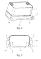
- FIG. 2 shows a heat exchanger 10 according to the invention, which has a heat exchanger block 11 and a mounting plate 12.
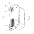
- the mounting plate 12 is in the FIG. 3 also shown once again individually.
- the mounting plate 12 has mounting portions 13, which serve to attach the mounting plate 12 and thus also the heat exchanger.
- the heat exchanger block 11 is arranged on the mounting plate 12 and connected thereto.
- the connection can also be made in this embodiment by soldering, welding, gluing, clamping, clipping, screws or other mechanical fastening.
- At least a portion 14 of a weakening of the mounting plate is provided between at least some of the mounting portions 13 and the heat exchanger block 11.
- This Area 14 of the weakening is in the embodiment of FIGS. 2 and 3 formed as a recess, such as a slot, wherein the weakening between the mounting portion and the heat exchanger block is arranged.
- the attachment areas are formed as fastening or screwing holes, wherein the weakening is introduced as a slot-shaped or arcuate recess in the mounting plate and arranged between a corner region of the heat exchanger block and the mounting area.
- the continuous through the material of the mounting plate slot as a recess and only partially continuous weakening be designed as a material reduction.
- This type of weakening is thus designed as a groove. It can be introduced on one or both sides of the mounting plate in the surface of the mounting plate.
- the arcuate contour of the recess between the mounting hole and the heat exchanger block is formed so that the arcuate contour of the recess follows the arcuate contour of the heat exchanger block in the corner substantially.
- the weakenings or recesses in the embodiment of the FIG. 3 not provided at each corner of the heat exchanger block. There are only two weakenings or recesses adjacent corners of a longitudinal side of the heat exchanger provided. In an alternative embodiment, the weakenings or recesses may also be provided adjacent to all four corners of the heat exchanger block.
- the recess 14 goes over into the fastening or screwing bore 13.
- the recess 14 is formed separately from the mounting hole 13 and spaced.
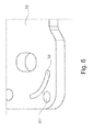
- FIG. 4 shows the heat exchanger 10 from its underside, wherein the mounting plate 12 with the mounting portions 13, which are formed as fastening or screw holes can be seen. Also, the recesses 14 can be seen in the region of the attachment regions 13, as they pass into the attachment regions 13. On the bottom connection areas 15, 16 are further provided to guide a second medium or a first medium on and out of the heat exchanger.
- FIG. 5 schematically shows again a section of a mounting plate 20 with a mounting portion 21 which is formed as a screw hole. With this screwing a weakening region 22 is connected, which is formed as a recess. In the embodiment of FIG. 5 the weakened region 22 merges into the fastening region 21, so that the two regions form a common recess. It is advantageous in the embodiment of FIG. 5 when the region of the recess 22 is arc-shaped and preferably arcuately around the inlet or outlet opening 23 for introducing or discharging a fluid in the heat exchanger or from the heat exchanger through an opening in the mounting plate.
- FIG. 6 shows a further embodiment of a section of a mounting plate 30 having a mounting portion 31 and a region of weakening 32, wherein the mounting portion 31 is spatially separated from the region of the weakening 32.
- the mounting portion 31 is in the embodiment of FIG. 6 shown as an opening or hole, wherein the region of the weakening is also shown as a recess.
- the fastening region extends around the heat exchanger block as a flange and is provided, for example, for a mechanical or material connection with a housing.
Landscapes
- Engineering & Computer Science (AREA)
- Physics & Mathematics (AREA)
- Thermal Sciences (AREA)
- Mechanical Engineering (AREA)
- General Engineering & Computer Science (AREA)
- Heat-Exchange Devices With Radiators And Conduit Assemblies (AREA)
Abstract
Description
- Die Erfindung betrifft einen Wärmeübertrager nach dem Oberbegriff von Anspruch 1.
- Zur Befestigung eines Wärmeübertragers an einer dafür vorgesehenen Position oder an einem Aggregat sind Befestigungsplatten als Befestigungselemente bekannt. Beispielsweise sind Stapelscheibenwärmeübertrager, wie beispielsweise Stapelscheibenölkühler, im Stand der Technik bekannt, welche mittels einer Befestigungsplatte an einem Motor-oder Getriebegehäuse eines Kraftfahrzeugs befestigbar sind.
- Dabei sind in der Befestigungsplatte zum Teil auch die Anschlüsse des Wärmeübertragers integriert, so dass durch die Befestigung des Wärmeübertragers am Aggregat auch gleichzeitig die Anschlussbereiche mit dafür vorgesehenen Anschlüssen des Aggregats fluiddicht verbunden werden können.
- Dabei ist es insbesondere bekannt geworden, dass der Wärmeübertrager mit an den Eckbereichen der Befestigungsplatte versehenen Bohrungen an Anschraubpunkte des Aggregats geschraubt wird.
- Alternativ sind auch Wärmeübertrager bekannt geworden, die mit der Befestigungsplatte in einem Gehäuse aufgenommen und befestigt sind, wobei in diesen Fällen die Befestigungsplatte einen überstehenden Rand aufweist, der als Befestigungsflansch verwendet wird.
- Solche Wärmeübertrager sind beispielweise durch die
DE 10 2005 048 452 A1 bekannt geworden. Darin ist ein Stapelscheibenölkühler offenbart, bei dem eine Befestigungsplatte mit Schraubbohrungen zur Befestigung vorgesehen ist und bei welchem der Wärmeübertragerblock auf die Befestigungsplatte aufgelötet ist. - Bei solchen Wärmeübertragern hat sich herausgestellt, dass aufgrund der Druckbeaufschlagung der Fluidkanäle sich mechanische Belastungen ergeben, die auf die Befestigungsplatte übertragen werden. So sind Biegeschwingungen der Fluidkanäle bekannt, die auf Befestigungsplatte bzw. auf die Grenzfläche zwischen Wärmeübertragerblock und Befestigungsplatte übertragen, die auf Dauer zu Ermüdungserscheinungen des Materials und damit zu Versagen des Wärmeübertragers führen.
- Es ist die Aufgabe der Erfindung, einen Wärmeübertrager zu schaffen, der gegenüber dem Stand der Technik weitergebildet ist, so dass er den Festigkeitsanforderungen besser genügt.
- Dies wird erreicht mit den Merkmalen von Anspruch 1.
- Ein vorteilhaftes Ausführungsbeispiel der Erfindung betrifft einen Wärmeübertrager mit einem Wärmeübertragerblock mit ersten Fluidkanälen zur Durchströmung eines ersten Fluids und mit zweiten Fluidkanälen zur Durchströmung für ein zweites Fluid, wobei der Wärmeübertrager eine Befestigungsplatte aufweist, welche den Wärmeübertragerblock trägt, wobei die Befestigung des Wärmeübertragers mittels der Befestigungsplatte erfolgt, wobei die Befestigungsplatte zur Befestigung Befestigungsbereiche aufweist, die benachbart zu dem Wärmeübertragerblock angeordnet sind, wobei zwischen den Befestigungsbereichen und dem Wärmeübertragerblock zumindest ein Bereich einer Schwächung der Befestigungsplatte vorliegt.
- Dabei ist es zweckmäßig, wenn die Befestigungsbereiche als Befestigungs-oder Verschraubungsbohrungen vorgesehen sind, wobei zwischen zumindest einer Befestigungs- oder Verschraubungsbohrung und dem Wärmeübertragerblock in der Befestigungsplatte eine Schwächung vorgesehen ist. Bei einem vorteilhaften Ausführungsbeispiel ist die Schwächung zwischen dem Wärmeübertragerblock und jeder Befestigungs-oder Verschraubungsbohrung vorgesehen.
- Dabei ist es alternativ besonders vorteilhaft, wenn die Befestigungsbereiche als Bereiche vorgesehen sind, mittels welchen die Befestigungsplatte mit einem Halteelement oder Gehäuse verbunden ist, wie verlötet oder mechanisch gefügt ist, wobei zwischen zumindest einem Befestigungsbereich und dem Wärmeübertragerblock in der Befestigungsplatte zumindest eine Schwächung vorgesehen ist.
- So ist es auch vorteilhaft, wenn die zumindest eine Schwächung eine Aussparung, wie eine Öffnung, in der Befestigungsplatte ist.
- Auch ist es alternativ vorteilhaft, wenn die zumindest eine Schwächung eine Materialreduktion in der Befestigungsplatte ist.
- Dabei ist es vorteilhaft, wenn die Schwächung, wie Aussparung oder Materialreduktion linienförmig, wie beispielsweise bogenförmig ausgestaltet ist. Bei Befestigungs- oder Verschraubungsbohrungen ist es vorteilhaft, wenn der bogenförmige Verlauf zumindest teilweise um die Bohrung herum verläuft oder angeordnet ist.
- Dabei ist es vorteilhaft, wenn die Aussparung oder Materialreduktion eine linienförmige oder bogenförmige Kontur aufweist, die zumindest teilweise zwischen einem Befestigungsbereich und einem Wärmeübertragerblock angeordnet ist.
- Dies führt dazu, dass die Befestigungsplatte gegenüber den Befestigungsbereichen schwingen kann, während die Befestigungsbereiche mit einem anderen Gegenstand, wie einem Motorblock, einem Aggregat oder Gehäuse verbunden sind.
- Auch ist es zweckmäßig, wenn der Wärmeübertragerblock ein Block aus aufeinandergestapelten Stapelscheiben oder Scheibenpaaren ist. Alternativ kann der Wärmeübertragerblock als Rohr-Rippen-Block ausgebildet sein.
- Auch ist es vorteilhaft, wenn ein erstes Medium Öl und ein zweites Medium ein Kühlfluid ist.
- Weitere vorteilhafte Ausgestaltungen sind durch die nachfolgende Figurenbeschreibung und durch die Unteransprüche beschrieben.
- Nachstehend wird die Erfindung auf der Grundlage zumindest eines Ausführungsbeispiels anhand der Zeichnungen näher erläutert. Es zeigen:
- Fig. 1
- einen Wärmeübertrager mit Wärmeübertragerblock und Befestigungsplatte,
- Fig. 2
- einen Wärmeübertrager mit Wärmeübertragerblock und Befestigungsplatte,
- Fig. 3
- eine Befestigungsplatte,
- Fig. 4
- einen Wärmeübertrager mit Wärmeübertragerblock und Befestigungsplatte,
- Fig. 5
- einen Ausschnitt einer Befestigungsplatte, und
- Fig. 6
- einen Ausschnitt einer Befestigungsplatte.
- Die
Figur 1 zeigt einen Wärmeübertrager 1 mit einem Wärmeübertragerblock 2 mit einer Befestigungsplatte 3. Der Wärmeübertragerblock 2 weist im inneren erste Fluidkanäle zur Durchströmung eines ersten Fluids und zweite Fluidkanäle zur Durchströmung eines zweiten Fluids auf. Diese Fluidkanäle können sich vorteilhaft abwechseln, so dass ein guter Wärmeübergang zwischen den beiden Fluiden erfolgen kann. Die Anschlussrohre 4, 5 dienen zur Zu- bzw. Ableitung des ersten oder des zweiten Fluides in den Wärmeübertragerblock 2 und zur dortigen Verteilung auf die jeweiligen Fluidkanäle. - Der Wärmeübertragerblock 2 ist vorteilhaft auf der Befestigungsplatte platziert und mit dieser verbunden. Dabei kann der Wärmeübertragerblock 2 mit der Befestigungsplatte verlötet oder auch verschweißt sein. Alternative Befestigungsmethoden, wie durch Kleben oder durch eine mechanische Verbindung durch Klipsen oder Schrauben oder Nieten, sind ebenso möglich.
- Wie zu erkennen ist, weist die Befestigungsplatte 3 außen liegende Befestigungsbereiche 6 auf, die der Befestigung des Wärmeübertragers an einem anderen Aggregat oder in einem Gehäuse etc. dienen, wobei die Befestigungsbereiche 6 benachbart zu dem Wärmeübertragerblock 2 in der Befestigungsplatte 3 angeordnet sind. Die Befestigungsbereiche 6 sind im Beispiel der
Figur 1 als Befestigungs- oder Verschraubungsbohrungen 7 ausgebildet. - Die
Figur 2 zeigt einen erfindungsgemäßen Wärmeübertrager 10, welcher einen Wärmeübertragerblock 11 und eine Befestigungsplatte 12 aufweist. Die Befestigungsplatte 12 ist in derFigur 3 auch noch einmal für sich betrachtet dargestellt. Die Befestigungsplatte12 weist Befestigungsbereiche 13 auf, die der Befestigung der Befestigungsplatte 12 und somit auch des Wärmeübertragers dienen. Dabei ist der Wärmeübertragerblock 11 auf der Befestigungsplatte 12 angeordnet und mit dieser verbunden. Die Verbindung kann auch in diesem Ausführungsbeispiel durch ein Verlöten, Verschweißen, Kleben, Klemmen, Klipsen, Schrauben oder eine anderweitige mechanische Befestigung erfolgen. - Wie in
Figur 2 und inFigur 3 zu erkennen ist, ist zwischen zumindest einigen der Befestigungsbereiche 13 und dem Wärmeübertragerblock 11 zumindest ein Bereich 14 einer Schwächung der Befestigungsplatte vorgesehen. Dieser Bereich 14 der Schwächung ist im Ausführungsbeispiel derFiguren 2 und 3 als Aussparung, wie als Schlitz, ausgebildet, wobei die Schwächung zwischen dem Befestigungsbereich und dem Wärmeübertragerblock angeordnet ist. Im Ausführungsbeispiel derFiguren 2 und 3 sind die Befestigungsbereiche als Befestigungs- oder Verschraubungsbohrungen ausgebildet, wobei die Schwächung als schlitzförmige oder bogenförmige Aussparung in die Befestigungsplatte eingebracht ist und zwischen einem Eckbereich des Wärmeübertragerblocks und dem Befestigungsbereich angeordnet. - Alternativ kann statt des durch das Material der Befestigungsplatte durchgängigen Schlitzes als Aussparung auch eine nur teilweise durchgängige Schwächung als Materialreduktion ausgebildet sein. Diese Art der Schwächung ist also etwa als Nut ausgebildet. Sie kann einseitig oder beidseitige der Befestigungsplatte in die Oberfläche der Befestigungsplatte eingebracht sein.
- Im vorliegenden Fall, ist die bogenförmige Kontur der Aussparung zwischen der Befestigungsbohrung und dem Wärmeübertragerblock so ausgebildet, dass die bogenförmige Kontur der Aussparung der bogenförmigen Kontur des Wärmeübertragerblocks im Eckbereich im Wesentlichen folgt.
- Dabei sind die Schwächungen bzw. Aussparungen im Ausführungsbeispiel der
Figur 3 nicht an jeder Ecke des Wärmeübertragerblocks vorgesehen. Es sind lediglich zwei Schwächungen bzw. Aussparungen benachbart von Ecken einer Längsseite des Wärmeübertragers vorgesehen. Bei einem alternativen Ausführungsbeispiel können die Schwächungen bzw. Aussparungen auch benachbart von allen vier Ecken des Wärmeübertragerblocks vorgesehen sein. - Im Ausführungsbeispiel der
Figur 3 geht die Aussparung 14 in die Befestigungs- oder Verschraubungsbohrung 13 über. In einem alternativen Ausführungsbeispiel, kann es auch vorteilhaft sein, wenn die Aussparung 14 von der Befestigungsbohrung 13 getrennt ausgebildet und beabstandet ist. - Die
Figur 4 zeigt den Wärmeübertrager 10 von seiner Unterseite, wobei die Befestigungsplatte 12 mit den Befestigungsbereichen 13, die als Befestigungs- oder Verschraubungsbohrungen ausgebildet sind zu erkennen ist. Auch sind die Aussparungen 14 im Bereich der Befestigungsbereiche 13 zu erkennen, wie sie in die Befestigungsbereiche 13 übergehen. Auf der Unterseite sind weiterhin Anschlussbereiche 15, 16 vorgesehen, um ein zweites Medium oder ein erstes Medium ein und aus dem Wärmeübertrager zu führen. - Die
Figur 5 zeigt schematisch noch einmal einen Ausschnitt einer Befestigungsplatte 20 mit einem Befestigungsbereich 21, der als Verschraubungsbohrung ausgebildet ist. Mit diesem Verschraubungsbereich ist ein Schwächungsbereich 22 verbunden, der als Aussparung ausgebildet ist. Im Ausführungsbeispiel derFigur 5 geht der Schwächungsbereich 22 in den Befestigungsbereich 21 über, so dass die beiden Bereiche eine gemeinsame Aussparung bilden. Vorteilhaft ist es bei dem Ausführungsbeispiel derFigur 5 , wenn der Bereich der Aussparung 22 bogenförmig ausgebildet ist und bevorzugt bogenförmig um die Ein- bzw. Auslassöffnung 23 zum Ein- oder Auslassen eines Fluids in den Wärmetauscher oder aus dem Wärmetauscher durch eine Öffnung in der Befestigungsplatte. - Die
Figur 6 zeigt ein weiteres Ausführungsbeispiel eines Ausschnitts einer Befestigungsplatte 30, die einen Befestigungsbereich 31 und einen Bereich einer Schwächung 32 aufweist, wobei der Befestigungsbereich 31 von dem Bereich der Schwächung 32 räumlich getrennt ist. Der Befestigungsbereich 31 ist im Ausführungsbeispiel derFigur 6 als Öffnung oder Bohrung dargestellt, wobei der Bereich der Schwächung ebenso als Aussparung dargestellt ist. In einem alternativen Ausführungsbeispiel kann es vorteilhaft sein, wenn der Befestigungsbereich als Flansch um den Wärmeübertragerblock herum verläuft und beispielsweise zur mechanischen oder stoffschlüssigen Verbindung mit einem Gehäuse vorgesehen ist.
Claims (9)
- Wärmeübertrager mit einem Wärmeübertragerblock mit ersten Fluidkanälen zur Durchströmung eines ersten Fluids und mit zweiten Fluidkanälen zur Durchströmung für ein zweites Fluid, wobei der Wärmeübertrager eine Befestigungsplatte aufweist, welche den Wärmeübertragerblock trägt, wobei die Befestigung des Wärmeübertragers mittels der Befestigungsplatte erfolgt, wobei die Befestigungsplatte zur Befestigung Befestigungsbereiche aufweist, die benachbart zu dem Wärmeübertragerblock angeordnet sind, dadurch gekennzeichnet, dass zwischen den Befestigungsbereichen und dem Wärmeübertragerblock zumindest ein Bereich einer Schwächung der Befestigungsplatte vorliegt.
- Wärmeübertrager nach Anspruch 1, dadurch gekennzeichnet, dass die Befestigungsbereiche als Befestigungs- oder Verschraubungsbohrungen vorgesehen sind, wobei zwischen zumindest einer Befestigungs- oder Verschraubungsbohrung und dem Wärmeübertragerblock in der Befestigungsplatte eine Schwächung vorgesehen ist.
- Wärmeübertrager nach Anspruch 1, dadurch gekennzeichnet, dass die Befestigungsbereiche als Bereiche vorgesehen sind, mittels welchen die Befestigungsplatte mit einem Halteelement oder Gehäuse verbunden ist, wie verlötet oder mechanisch gefügt ist, wobei zwischen zumindest einem Befestigungsbereich und dem Wärmeübertragerblock in der Befestigungsplatte zumindest eine Schwächung vorgesehen ist
- Wärmeübertrager nach Anspruch 2 oder 3, dadurch gekennzeichnet, dass die zumindest eine Schwächung eine Aussparung in der Befestigungsplatte ist.
- Wärmeübertrager nach Anspruch 2 oder 3, dadurch gekennzeichnet, dass die zumindest eine Schwächung eine Materialreduktion in der Befestigungsplatte ist.
- Wärmeübertrager nach einem der vorhergehenden Ansprüche, dadurch gekennzeichnet, dass die Aussparung oder Materialreduktion eine linienförmige oder bogenförmige Kontur aufweist, die teilweise um eine Befestigungs- oder Verschraubungsbohrung angeordnet ist.
- Wärmeübertrager nach einem der vorhergehenden Ansprüche, dadurch gekennzeichnet, dass die Aussparung oder Materialreduktion eine linienförmige oder bogenförmige Kontur aufweist, die zumindest teilweise zwischen einem Befestigungsbereich und einem Wärmeübertragerblock angeordnet ist.
- Wärmeübertrager nach einem der vorhergehenden Ansprüche, dadurch gekennzeichnet, dass der Wärmeübertragerblock ein Block aus aufeinandergestapelten Stapelscheiben oder Scheibenpaaren ist.
- Wärmeübertrager nach einem der vorhergehenden Ansprüche, dadurch gekennzeichnet, dass ein erstes Medium Öl und ein zweites Medium ein Kühlfluid ist.
Applications Claiming Priority (1)
| Application Number | Priority Date | Filing Date | Title |
|---|---|---|---|
| DE102012204729A DE102012204729A1 (de) | 2012-03-23 | 2012-03-23 | Wärmeübertrager |
Publications (3)
| Publication Number | Publication Date |
|---|---|
| EP2645043A2 true EP2645043A2 (de) | 2013-10-02 |
| EP2645043A3 EP2645043A3 (de) | 2015-12-30 |
| EP2645043B1 EP2645043B1 (de) | 2021-05-19 |
Family
ID=47915527
Family Applications (1)
| Application Number | Title | Priority Date | Filing Date |
|---|---|---|---|
| EP13160498.5A Active EP2645043B1 (de) | 2012-03-23 | 2013-03-21 | Wärmeübertrager |
Country Status (3)
| Country | Link |
|---|---|
| EP (1) | EP2645043B1 (de) |
| CN (1) | CN203385315U (de) |
| DE (1) | DE102012204729A1 (de) |
Families Citing this family (1)
| Publication number | Priority date | Publication date | Assignee | Title |
|---|---|---|---|---|
| DE102013214403B4 (de) | 2013-07-23 | 2026-05-13 | Bayerische Motoren Werke Aktiengesellschaft | Grundplatte für einen Fahrzeugwärmetauscher, Verfahren zu ihrer Herstellung, Wärmetauscher und Ölfiltermodul |
Family Cites Families (10)
| Publication number | Priority date | Publication date | Assignee | Title |
|---|---|---|---|---|
| DE102005048452A1 (de) | 2004-10-11 | 2006-04-20 | Behr Gmbh & Co. Kg | Wärmeübertrager |
| DE102005048294A1 (de) * | 2005-10-08 | 2007-04-12 | Modine Manufacturing Co., Racine | Gelöteter Wärmetauscher und Herstellungsverfahren |
| DE102007030563A1 (de) * | 2007-06-30 | 2009-01-02 | Modine Manufacturing Co., Racine | Plattenwärmetauscher und Montageverfahren |
| DE102009030095A1 (de) * | 2009-06-22 | 2010-12-23 | Behr Gmbh & Co. Kg | Stapelscheibenkühler |
| AT508537B1 (de) * | 2009-07-16 | 2011-04-15 | Mahle Int Gmbh | Plattenwärmetauscher mit mehreren übereinander gestapelten platten |
| DE102009034752A1 (de) * | 2009-07-25 | 2011-02-10 | Modine Europe Gmbh | Wärmetauscher, beispielsweise Ölkühler |
| DE102009035239A1 (de) * | 2009-07-29 | 2011-04-14 | Behr Gmbh & Co. Kg | Stapelscheiben-Kühler, Verwendung des Stapelscheiben-Kühlers und Brennkraftmaschine mit einem Stapelscheiben-Kühler |
| US20110024095A1 (en) * | 2009-07-30 | 2011-02-03 | Mark Kozdras | Heat Exchanger with End Plate Providing Mounting Flange |
| FR2948755B1 (fr) * | 2009-07-30 | 2015-08-21 | Dana Canada Corp | Echangeur de chaleur dont la plaque d'extremite fournit le rebord de montage. |
| DE202011002197U1 (de) * | 2011-02-01 | 2012-02-02 | Dana Gmbh | Wärmetauscher |
-
2012
- 2012-03-23 DE DE102012204729A patent/DE102012204729A1/de not_active Withdrawn
-
2013
- 2013-03-20 CN CN201320129727.0U patent/CN203385315U/zh not_active Expired - Lifetime
- 2013-03-21 EP EP13160498.5A patent/EP2645043B1/de active Active
Non-Patent Citations (1)
| Title |
|---|
| None * |
Also Published As
| Publication number | Publication date |
|---|---|
| EP2645043A3 (de) | 2015-12-30 |
| CN203385315U (zh) | 2014-01-08 |
| EP2645043B1 (de) | 2021-05-19 |
| DE102012204729A1 (de) | 2013-09-26 |
Similar Documents
| Publication | Publication Date | Title |
|---|---|---|
| EP2205922B1 (de) | Wärmetauscher, insbesondere ölkühler | |
| EP0828980B1 (de) | Wärmetauscher | |
| EP2267390B2 (de) | Stapelscheibenkühler | |
| EP2236969B1 (de) | Stapelscheiben-Wärmeübertrager für hohe Temperaturwechselbeanspruchung | |
| WO1998054527A2 (de) | Plattenwärmetauscher, insbesondere öl/kühlmittel-kühler für kraftfahrzeuge | |
| DE102013220313B4 (de) | Stapelscheiben-Wärmetauscher | |
| EP2809973B1 (de) | Metallische flachdichtung | |
| DE69823322T2 (de) | Metalldichtung mit Kantenstützscheibe | |
| DE102013207180A1 (de) | Wärmeübertrager mit in einem Sammelkanal angeordneten Einsatz | |
| DE3520876C1 (de) | Vorrichtung zum Zuführen von Schmieröl zu den Reibstellen einer Nockenwelle | |
| EP1443251B1 (de) | Flanscheinheit | |
| AT507352B1 (de) | Kühlanordnung | |
| DE102011000547B4 (de) | Wärmeableitvorrichtung | |
| EP3234313B1 (de) | Ölkühler für ein ölfiltermodul eines kraftfahrzeugs | |
| EP1985955B1 (de) | Plattenwärmetauscher | |
| EP2645043B1 (de) | Wärmeübertrager | |
| DE102010001828A1 (de) | Stapelanordnung | |
| EP1772633B1 (de) | Vorrichtung zum Verschrauben zweier Bauteile mit Toleranzausgleich | |
| DE102007003920A1 (de) | Kühler für ein elektrisches oder elektronisches Bauteil | |
| DE102013204345A1 (de) | Dichtung zum Halten von Schrauben | |
| DE102005002063A1 (de) | Stapelscheiben -Wärmetauscher | |
| DE602005000841T3 (de) | Dichtung | |
| DE102004040892A1 (de) | Schmiermittelfilter für eine Brennkraftmaschine | |
| DE202004016183U1 (de) | Wärmetauscher für einen Verbrennungsmotor | |
| WO2017167872A1 (de) | Stapelscheibenwärmetauscher |
Legal Events
| Date | Code | Title | Description |
|---|---|---|---|
| PUAI | Public reference made under article 153(3) epc to a published international application that has entered the european phase |
Free format text: ORIGINAL CODE: 0009012 |
|
| AK | Designated contracting states |
Kind code of ref document: A2 Designated state(s): AL AT BE BG CH CY CZ DE DK EE ES FI FR GB GR HR HU IE IS IT LI LT LU LV MC MK MT NL NO PL PT RO RS SE SI SK SM TR |
|
| AX | Request for extension of the european patent |
Extension state: BA ME |
|
| RAP1 | Party data changed (applicant data changed or rights of an application transferred) |
Owner name: MAHLE BEHR GMBH & CO. KG |
|
| PUAL | Search report despatched |
Free format text: ORIGINAL CODE: 0009013 |
|
| AK | Designated contracting states |
Kind code of ref document: A3 Designated state(s): AL AT BE BG CH CY CZ DE DK EE ES FI FR GB GR HR HU IE IS IT LI LT LU LV MC MK MT NL NO PL PT RO RS SE SI SK SM TR |
|
| AX | Request for extension of the european patent |
Extension state: BA ME |
|
| RIC1 | Information provided on ipc code assigned before grant |
Ipc: F28D 9/00 20060101ALI20151120BHEP Ipc: F28F 9/00 20060101AFI20151120BHEP Ipc: F28F 9/02 20060101ALI20151120BHEP Ipc: F28D 21/00 20060101ALI20151120BHEP |
|
| 17P | Request for examination filed |
Effective date: 20160630 |
|
| RBV | Designated contracting states (corrected) |
Designated state(s): AL AT BE BG CH CY CZ DE DK EE ES FI FR GB GR HR HU IE IS IT LI LT LU LV MC MK MT NL NO PL PT RO RS SE SI SK SM TR |
|
| STAA | Information on the status of an ep patent application or granted ep patent |
Free format text: STATUS: EXAMINATION IS IN PROGRESS |
|
| 17Q | First examination report despatched |
Effective date: 20181015 |
|
| GRAP | Despatch of communication of intention to grant a patent |
Free format text: ORIGINAL CODE: EPIDOSNIGR1 |
|
| STAA | Information on the status of an ep patent application or granted ep patent |
Free format text: STATUS: GRANT OF PATENT IS INTENDED |
|
| INTG | Intention to grant announced |
Effective date: 20201208 |
|
| GRAJ | Information related to disapproval of communication of intention to grant by the applicant or resumption of examination proceedings by the epo deleted |
Free format text: ORIGINAL CODE: EPIDOSDIGR1 |
|
| STAA | Information on the status of an ep patent application or granted ep patent |
Free format text: STATUS: EXAMINATION IS IN PROGRESS |
|
| GRAS | Grant fee paid |
Free format text: ORIGINAL CODE: EPIDOSNIGR3 |
|
| STAA | Information on the status of an ep patent application or granted ep patent |
Free format text: STATUS: GRANT OF PATENT IS INTENDED |
|
| GRAJ | Information related to disapproval of communication of intention to grant by the applicant or resumption of examination proceedings by the epo deleted |
Free format text: ORIGINAL CODE: EPIDOSDIGR1 |
|
| GRAP | Despatch of communication of intention to grant a patent |
Free format text: ORIGINAL CODE: EPIDOSNIGR1 |
|
| INTC | Intention to grant announced (deleted) | ||
| STAA | Information on the status of an ep patent application or granted ep patent |
Free format text: STATUS: EXAMINATION IS IN PROGRESS |
|
| GRAS | Grant fee paid |
Free format text: ORIGINAL CODE: EPIDOSNIGR3 |
|
| STAA | Information on the status of an ep patent application or granted ep patent |
Free format text: STATUS: GRANT OF PATENT IS INTENDED |
|
| GRAP | Despatch of communication of intention to grant a patent |
Free format text: ORIGINAL CODE: EPIDOSNIGR1 |
|
| GRAA | (expected) grant |
Free format text: ORIGINAL CODE: 0009210 |
|
| STAA | Information on the status of an ep patent application or granted ep patent |
Free format text: STATUS: THE PATENT HAS BEEN GRANTED |
|
| INTG | Intention to grant announced |
Effective date: 20210330 |
|
| AK | Designated contracting states |
Kind code of ref document: B1 Designated state(s): AL AT BE BG CH CY CZ DE DK EE ES FI FR GB GR HR HU IE IS IT LI LT LU LV MC MK MT NL NO PL PT RO RS SE SI SK SM TR |
|
| REG | Reference to a national code |
Ref country code: GB Ref legal event code: FG4D Free format text: NOT ENGLISH |
|
| REG | Reference to a national code |
Ref country code: CH Ref legal event code: EP |
|
| REG | Reference to a national code |
Ref country code: DE Ref legal event code: R096 Ref document number: 502013015720 Country of ref document: DE |
|
| REG | Reference to a national code |
Ref country code: AT Ref legal event code: REF Ref document number: 1394393 Country of ref document: AT Kind code of ref document: T Effective date: 20210615 |
|
| REG | Reference to a national code |
Ref country code: IE Ref legal event code: FG4D Free format text: LANGUAGE OF EP DOCUMENT: GERMAN |
|
| REG | Reference to a national code |
Ref country code: LT Ref legal event code: MG9D |
|
| REG | Reference to a national code |
Ref country code: NL Ref legal event code: MP Effective date: 20210519 |
|
| PG25 | Lapsed in a contracting state [announced via postgrant information from national office to epo] |
Ref country code: HR Free format text: LAPSE BECAUSE OF FAILURE TO SUBMIT A TRANSLATION OF THE DESCRIPTION OR TO PAY THE FEE WITHIN THE PRESCRIBED TIME-LIMIT Effective date: 20210519 Ref country code: BG Free format text: LAPSE BECAUSE OF FAILURE TO SUBMIT A TRANSLATION OF THE DESCRIPTION OR TO PAY THE FEE WITHIN THE PRESCRIBED TIME-LIMIT Effective date: 20210819 Ref country code: FI Free format text: LAPSE BECAUSE OF FAILURE TO SUBMIT A TRANSLATION OF THE DESCRIPTION OR TO PAY THE FEE WITHIN THE PRESCRIBED TIME-LIMIT Effective date: 20210519 Ref country code: LT Free format text: LAPSE BECAUSE OF FAILURE TO SUBMIT A TRANSLATION OF THE DESCRIPTION OR TO PAY THE FEE WITHIN THE PRESCRIBED TIME-LIMIT Effective date: 20210519 |
|
| PG25 | Lapsed in a contracting state [announced via postgrant information from national office to epo] |
Ref country code: LV Free format text: LAPSE BECAUSE OF FAILURE TO SUBMIT A TRANSLATION OF THE DESCRIPTION OR TO PAY THE FEE WITHIN THE PRESCRIBED TIME-LIMIT Effective date: 20210519 Ref country code: GR Free format text: LAPSE BECAUSE OF FAILURE TO SUBMIT A TRANSLATION OF THE DESCRIPTION OR TO PAY THE FEE WITHIN THE PRESCRIBED TIME-LIMIT Effective date: 20210820 Ref country code: IS Free format text: LAPSE BECAUSE OF FAILURE TO SUBMIT A TRANSLATION OF THE DESCRIPTION OR TO PAY THE FEE WITHIN THE PRESCRIBED TIME-LIMIT Effective date: 20210919 Ref country code: SE Free format text: LAPSE BECAUSE OF FAILURE TO SUBMIT A TRANSLATION OF THE DESCRIPTION OR TO PAY THE FEE WITHIN THE PRESCRIBED TIME-LIMIT Effective date: 20210519 Ref country code: RS Free format text: LAPSE BECAUSE OF FAILURE TO SUBMIT A TRANSLATION OF THE DESCRIPTION OR TO PAY THE FEE WITHIN THE PRESCRIBED TIME-LIMIT Effective date: 20210519 Ref country code: ES Free format text: LAPSE BECAUSE OF FAILURE TO SUBMIT A TRANSLATION OF THE DESCRIPTION OR TO PAY THE FEE WITHIN THE PRESCRIBED TIME-LIMIT Effective date: 20210519 Ref country code: PT Free format text: LAPSE BECAUSE OF FAILURE TO SUBMIT A TRANSLATION OF THE DESCRIPTION OR TO PAY THE FEE WITHIN THE PRESCRIBED TIME-LIMIT Effective date: 20210920 Ref country code: PL Free format text: LAPSE BECAUSE OF FAILURE TO SUBMIT A TRANSLATION OF THE DESCRIPTION OR TO PAY THE FEE WITHIN THE PRESCRIBED TIME-LIMIT Effective date: 20210519 Ref country code: NO Free format text: LAPSE BECAUSE OF FAILURE TO SUBMIT A TRANSLATION OF THE DESCRIPTION OR TO PAY THE FEE WITHIN THE PRESCRIBED TIME-LIMIT Effective date: 20210819 |
|
| PG25 | Lapsed in a contracting state [announced via postgrant information from national office to epo] |
Ref country code: NL Free format text: LAPSE BECAUSE OF FAILURE TO SUBMIT A TRANSLATION OF THE DESCRIPTION OR TO PAY THE FEE WITHIN THE PRESCRIBED TIME-LIMIT Effective date: 20210519 |
|
| PG25 | Lapsed in a contracting state [announced via postgrant information from national office to epo] |
Ref country code: DK Free format text: LAPSE BECAUSE OF FAILURE TO SUBMIT A TRANSLATION OF THE DESCRIPTION OR TO PAY THE FEE WITHIN THE PRESCRIBED TIME-LIMIT Effective date: 20210519 Ref country code: CZ Free format text: LAPSE BECAUSE OF FAILURE TO SUBMIT A TRANSLATION OF THE DESCRIPTION OR TO PAY THE FEE WITHIN THE PRESCRIBED TIME-LIMIT Effective date: 20210519 Ref country code: EE Free format text: LAPSE BECAUSE OF FAILURE TO SUBMIT A TRANSLATION OF THE DESCRIPTION OR TO PAY THE FEE WITHIN THE PRESCRIBED TIME-LIMIT Effective date: 20210519 Ref country code: SK Free format text: LAPSE BECAUSE OF FAILURE TO SUBMIT A TRANSLATION OF THE DESCRIPTION OR TO PAY THE FEE WITHIN THE PRESCRIBED TIME-LIMIT Effective date: 20210519 Ref country code: SM Free format text: LAPSE BECAUSE OF FAILURE TO SUBMIT A TRANSLATION OF THE DESCRIPTION OR TO PAY THE FEE WITHIN THE PRESCRIBED TIME-LIMIT Effective date: 20210519 Ref country code: RO Free format text: LAPSE BECAUSE OF FAILURE TO SUBMIT A TRANSLATION OF THE DESCRIPTION OR TO PAY THE FEE WITHIN THE PRESCRIBED TIME-LIMIT Effective date: 20210519 |
|
| REG | Reference to a national code |
Ref country code: DE Ref legal event code: R097 Ref document number: 502013015720 Country of ref document: DE |
|
| PLBE | No opposition filed within time limit |
Free format text: ORIGINAL CODE: 0009261 |
|
| STAA | Information on the status of an ep patent application or granted ep patent |
Free format text: STATUS: NO OPPOSITION FILED WITHIN TIME LIMIT |
|
| 26N | No opposition filed |
Effective date: 20220222 |
|
| PG25 | Lapsed in a contracting state [announced via postgrant information from national office to epo] |
Ref country code: IS Free format text: LAPSE BECAUSE OF FAILURE TO SUBMIT A TRANSLATION OF THE DESCRIPTION OR TO PAY THE FEE WITHIN THE PRESCRIBED TIME-LIMIT Effective date: 20210919 Ref country code: AL Free format text: LAPSE BECAUSE OF FAILURE TO SUBMIT A TRANSLATION OF THE DESCRIPTION OR TO PAY THE FEE WITHIN THE PRESCRIBED TIME-LIMIT Effective date: 20210519 |
|
| PG25 | Lapsed in a contracting state [announced via postgrant information from national office to epo] |
Ref country code: IT Free format text: LAPSE BECAUSE OF FAILURE TO SUBMIT A TRANSLATION OF THE DESCRIPTION OR TO PAY THE FEE WITHIN THE PRESCRIBED TIME-LIMIT Effective date: 20210519 |
|
| REG | Reference to a national code |
Ref country code: DE Ref legal event code: R119 Ref document number: 502013015720 Country of ref document: DE |
|
| PG25 | Lapsed in a contracting state [announced via postgrant information from national office to epo] |
Ref country code: MC Free format text: LAPSE BECAUSE OF FAILURE TO SUBMIT A TRANSLATION OF THE DESCRIPTION OR TO PAY THE FEE WITHIN THE PRESCRIBED TIME-LIMIT Effective date: 20210519 |
|
| REG | Reference to a national code |
Ref country code: CH Ref legal event code: PL |
|
| GBPC | Gb: european patent ceased through non-payment of renewal fee |
Effective date: 20220321 |
|
| REG | Reference to a national code |
Ref country code: BE Ref legal event code: MM Effective date: 20220331 |
|
| PG25 | Lapsed in a contracting state [announced via postgrant information from national office to epo] |
Ref country code: LU Free format text: LAPSE BECAUSE OF NON-PAYMENT OF DUE FEES Effective date: 20220321 Ref country code: LI Free format text: LAPSE BECAUSE OF NON-PAYMENT OF DUE FEES Effective date: 20220331 Ref country code: IE Free format text: LAPSE BECAUSE OF NON-PAYMENT OF DUE FEES Effective date: 20220321 Ref country code: GB Free format text: LAPSE BECAUSE OF NON-PAYMENT OF DUE FEES Effective date: 20220321 Ref country code: FR Free format text: LAPSE BECAUSE OF NON-PAYMENT OF DUE FEES Effective date: 20220331 Ref country code: DE Free format text: LAPSE BECAUSE OF NON-PAYMENT OF DUE FEES Effective date: 20221001 Ref country code: CH Free format text: LAPSE BECAUSE OF NON-PAYMENT OF DUE FEES Effective date: 20220331 |
|
| PG25 | Lapsed in a contracting state [announced via postgrant information from national office to epo] |
Ref country code: BE Free format text: LAPSE BECAUSE OF NON-PAYMENT OF DUE FEES Effective date: 20220331 |
|
| REG | Reference to a national code |
Ref country code: AT Ref legal event code: MM01 Ref document number: 1394393 Country of ref document: AT Kind code of ref document: T Effective date: 20220321 |
|
| PG25 | Lapsed in a contracting state [announced via postgrant information from national office to epo] |
Ref country code: AT Free format text: LAPSE BECAUSE OF NON-PAYMENT OF DUE FEES Effective date: 20220321 |
|
| PG25 | Lapsed in a contracting state [announced via postgrant information from national office to epo] |
Ref country code: HU Free format text: LAPSE BECAUSE OF FAILURE TO SUBMIT A TRANSLATION OF THE DESCRIPTION OR TO PAY THE FEE WITHIN THE PRESCRIBED TIME-LIMIT; INVALID AB INITIO Effective date: 20130321 |
|
| PG25 | Lapsed in a contracting state [announced via postgrant information from national office to epo] |
Ref country code: MK Free format text: LAPSE BECAUSE OF FAILURE TO SUBMIT A TRANSLATION OF THE DESCRIPTION OR TO PAY THE FEE WITHIN THE PRESCRIBED TIME-LIMIT Effective date: 20210519 Ref country code: CY Free format text: LAPSE BECAUSE OF FAILURE TO SUBMIT A TRANSLATION OF THE DESCRIPTION OR TO PAY THE FEE WITHIN THE PRESCRIBED TIME-LIMIT Effective date: 20210519 |
|
| PG25 | Lapsed in a contracting state [announced via postgrant information from national office to epo] |
Ref country code: MT Free format text: LAPSE BECAUSE OF FAILURE TO SUBMIT A TRANSLATION OF THE DESCRIPTION OR TO PAY THE FEE WITHIN THE PRESCRIBED TIME-LIMIT Effective date: 20210519 |
|
| PG25 | Lapsed in a contracting state [announced via postgrant information from national office to epo] |
Ref country code: TR Free format text: LAPSE BECAUSE OF FAILURE TO SUBMIT A TRANSLATION OF THE DESCRIPTION OR TO PAY THE FEE WITHIN THE PRESCRIBED TIME-LIMIT Effective date: 20210519 |