EP2644422A1 - Open roof construction for a vehicle - Google Patents
Open roof construction for a vehicle Download PDFInfo
- Publication number
- EP2644422A1 EP2644422A1 EP12161182.6A EP12161182A EP2644422A1 EP 2644422 A1 EP2644422 A1 EP 2644422A1 EP 12161182 A EP12161182 A EP 12161182A EP 2644422 A1 EP2644422 A1 EP 2644422A1
- Authority
- EP
- European Patent Office
- Prior art keywords
- roof
- telescoping
- construction according
- panels
- roof construction
- Prior art date
- Legal status (The legal status is an assumption and is not a legal conclusion. Google has not performed a legal analysis and makes no representation as to the accuracy of the status listed.)
- Granted
Links
Images


Classifications
-
- B—PERFORMING OPERATIONS; TRANSPORTING
- B60—VEHICLES IN GENERAL
- B60J—WINDOWS, WINDSCREENS, NON-FIXED ROOFS, DOORS, OR SIMILAR DEVICES FOR VEHICLES; REMOVABLE EXTERNAL PROTECTIVE COVERINGS SPECIALLY ADAPTED FOR VEHICLES
- B60J7/00—Non-fixed roofs; Roofs with movable panels, e.g. rotary sunroofs
- B60J7/02—Non-fixed roofs; Roofs with movable panels, e.g. rotary sunroofs of sliding type, e.g. comprising guide shoes
- B60J7/04—Non-fixed roofs; Roofs with movable panels, e.g. rotary sunroofs of sliding type, e.g. comprising guide shoes with rigid plate-like element or elements, e.g. open roofs with harmonica-type folding rigid panels
- B60J7/057—Driving or actuating arrangements e.g. manually operated levers or knobs
-
- B—PERFORMING OPERATIONS; TRANSPORTING
- B60—VEHICLES IN GENERAL
- B60J—WINDOWS, WINDSCREENS, NON-FIXED ROOFS, DOORS, OR SIMILAR DEVICES FOR VEHICLES; REMOVABLE EXTERNAL PROTECTIVE COVERINGS SPECIALLY ADAPTED FOR VEHICLES
- B60J7/00—Non-fixed roofs; Roofs with movable panels, e.g. rotary sunroofs
- B60J7/02—Non-fixed roofs; Roofs with movable panels, e.g. rotary sunroofs of sliding type, e.g. comprising guide shoes
- B60J7/04—Non-fixed roofs; Roofs with movable panels, e.g. rotary sunroofs of sliding type, e.g. comprising guide shoes with rigid plate-like element or elements, e.g. open roofs with harmonica-type folding rigid panels
- B60J7/047—Non-fixed roofs; Roofs with movable panels, e.g. rotary sunroofs of sliding type, e.g. comprising guide shoes with rigid plate-like element or elements, e.g. open roofs with harmonica-type folding rigid panels movable to overlapping or nested relationship
-
- B—PERFORMING OPERATIONS; TRANSPORTING
- B60—VEHICLES IN GENERAL
- B60J—WINDOWS, WINDSCREENS, NON-FIXED ROOFS, DOORS, OR SIMILAR DEVICES FOR VEHICLES; REMOVABLE EXTERNAL PROTECTIVE COVERINGS SPECIALLY ADAPTED FOR VEHICLES
- B60J7/00—Non-fixed roofs; Roofs with movable panels, e.g. rotary sunroofs
- B60J7/02—Non-fixed roofs; Roofs with movable panels, e.g. rotary sunroofs of sliding type, e.g. comprising guide shoes
- B60J7/026—Non-fixed roofs; Roofs with movable panels, e.g. rotary sunroofs of sliding type, e.g. comprising guide shoes with rigid non plate-like elements, e.g. for convertible vehicles
-
- B—PERFORMING OPERATIONS; TRANSPORTING
- B60—VEHICLES IN GENERAL
- B60J—WINDOWS, WINDSCREENS, NON-FIXED ROOFS, DOORS, OR SIMILAR DEVICES FOR VEHICLES; REMOVABLE EXTERNAL PROTECTIVE COVERINGS SPECIALLY ADAPTED FOR VEHICLES
- B60J7/00—Non-fixed roofs; Roofs with movable panels, e.g. rotary sunroofs
- B60J7/02—Non-fixed roofs; Roofs with movable panels, e.g. rotary sunroofs of sliding type, e.g. comprising guide shoes
- B60J7/026—Non-fixed roofs; Roofs with movable panels, e.g. rotary sunroofs of sliding type, e.g. comprising guide shoes with rigid non plate-like elements, e.g. for convertible vehicles
- B60J7/028—Non-fixed roofs; Roofs with movable panels, e.g. rotary sunroofs of sliding type, e.g. comprising guide shoes with rigid non plate-like elements, e.g. for convertible vehicles the sliding movement being combined with a pivoting movement
Definitions
- the invention relates to an open roof construction for a vehicle, comprising a number of separate roof panels which are movable between a closed position for closing a roof opening of said vehicle and an opened position for at least partially freeing said roof opening.
- the open roof construction is characterized in that a telescoping mechanism is provided for moving said number of roof panels, substantially in a longitudinal direction of the vehicle, between the closed and opened positions, which telescoping mechanism is provided with a number of telescoping members which in a telescoping manner are movable relative to each other and wherein each panel is attached to and moved by a different one of said telescoping members.
- the invention also relates to a case in which only one roof panel is present.
- the telescoping mechanism comprises two telescoping members, of which one is attached to the roof panel and the other is attached to a stationary part of the vehicle (e.g. the vehicle body).
- the open roof construction according to the present invention is provided with a single telescoping mechanism located substantially along a longitudinal centre line of said roof panels.
- a single telescoping mechanism located substantially along a longitudinal centre line of said roof panels.
- Such an embodiment may be used when the dimensions (and, thus, weight) of the roof panels are moderate and sufficient stability may be obtained by just a single, central, telescoping mechanism.
- the open roof construction may be provided with two telescoping mechanisms located substantially at the opposite longitudinal edges of said roof panels.
- each telescoping mechanism moves in a fixed direction. Said fixed direction will be determined by the relative (translating) telescoping movement of the telescoping members of the telescoping mechanism.
- each telescoping mechanism may move in a variable direction.
- each telescoping mechanism is mounted for a rotation about an axis of rotation extending substantially in a transverse direction.
- the direction of the telescoping movement of the telescoping mechanism may be varied (at any desired stage of the movement, for example before or during said movement).
- the telescoping mechanism is devised for carrying out its telescoping movement and its rotation about said axis of rotation substantially successively. That means that one of said movements (telescoping movement or rotation) substantially will be completed before the other one of said movements is carried out. For example, when moving the roof panels from the closed to the fully opened position initially a translating telescoping movement may be carried out, followed by a rotation of the telescoping mechanism.
- the telescoping mechanism may be devised for carrying out its telescoping movement and its rotation about said axis of rotation at least partly simultaneously. This means that a translating telescoping movement and said rotation at least partly are carried out at the same time.
- each telescoping mechanism is attached to the vehicle at a position behind the roof opening, as seen in the longitudinal direction of said vehicle, such that the panels, when moved to the fully opened position, are located substantially behind said roof opening.
- the free roof opening, in the fully opened position of the roof panels may be maximised.
- the open roof construction according to the present invention may be applied to a vehicle of the type having a rear trunk, in which case the telescoping mechanism may be devised for, in their fully opened position, positioning the panels in said trunk. It is noted, that especially in such a case the embodiment is favourable in which each telescoping mechanism can move in a variable direction (and, for example, may rotate around a transverse axis of rotation).
- the roof opening comprises two opposite longitudinal edges which are defined by cant rails which are devised for maintaining their position along said longitudinal edges when the panels move between the closed and opened positions.
- said cant rails will maintain their original position at opposite longitudinal edges of the roof opening (connecting a forward body part -e.g. the so called A-beam-of the vehicle with a rearward body part -e.g. the so called C-beam- when the roof panels are moved to an opened position and, thus, add to the overall constructional stability of the vehicle).
- the roof opening comprises two opposite longitudinal edges which are defined by cant rails which are devised for moving along with the panels when these move between the closed and opened positions.
- cant rails which are devised for moving along with the panels when these move between the closed and opened positions.
- each cant rail may comprise a number of cant rail members attached to longitudinal side edges of respective ones of the roof panels, which cant rail members are provided with cooperating connecting members for establishing a connection between successive cant rail members in the closed position of the roof panels.
- the connecting members ensure that the cant rail members define rigid cant rails.
- each roof panel is attached to a respective telescoping member in a rigid manner
- the roof panels are attached to the respective telescoping members in a manner to allow a change of the relative position between a roof panel and the corresponding telescoping member. This allows to achieve more complicated movements of the roof panels (for example to take into account space limitations).
- each roof panel is attached to a respective telescoping member through an axis of rotation extending substantially in a transverse direction.
- the rotation of a roof panel around such axis may be synchronised with the movement of the telescoping mechanism.
- the telescoping mechanism may be rectilinear or curved.
- the resulting translating movement then also will be according to a straight or curved line, respectively.
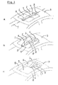
- a first embodiment of a roof construction for a vehicle comprising two separate roof panels 1,2 which are movable between a closed position ( figure 1a ) for closing a roof opening 3 of said vehicle and an opened position ( figure 1c ) for at least partially freeing said roof opening.
- a telescoping mechanism 4 is provided for moving said roof panels 1,2, substantially in a longitudinal direction 5 of the vehicle, between the closed and opened positions.
- the telescoping mechanism 4 is provided with a number of telescoping members 6-8 which in a telescoping manner are movable relative to each other.
- a first panel 1 is attached to and moved by telescoping member 6, whereas a second panel 2 is attached to and moved by telescoping member 7.
- telescoping member 8 is attached to a stationary roof part 9 at a position behind the roof opening 3, as seen in the longitudinal direction of said vehicle, such that the panels 1,2, when moved to the fully opened position, are located substantially behind said roof opening 3.
- the open roof construction is provided with a single telescoping mechanism 4 located substantially along a longitudinal centre line of said roof panels 1,2.
- the telescoping mechanism 4 moves in a fixed direction according to a translational movement, and thus its telescoping member 8 may be attached to the stationary roof part 9 in a fixed manner.
- each roof panel 1,2 is attached to the respective telescoping members 6,7 in a manner to allow a change of the relative position between a roof panel and the corresponding telescoping member.
- each roof panel 1,2 may be attached to the respective telescoping member 6,7 through an axis of rotation 10 (illustrated schematically in figure 1b only) extending substantially in a transverse direction (and in the illustrated embodiment in the immediate vicinity of a leading edge 11 of the respective roof panel).
- roof opening 3 comprises two opposite longitudinal edges which are defined by cant rails 12 which are devised for maintaining their position along said longitudinal edges when the panels 1,2 move between the closed and opened positions.
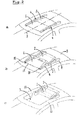
- Figure 2 shows (again in three successive positions) a second embodiment of the open roof construction according to the present invention which closely resembles the embodiment according to figure 1 and in which like parts are indicated by like reference numbers.
- this second embodiment comprises two telescoping mechanisms 4 located substantially at the opposite longitudinal edges of the roof panels 1,2.
- the operation of this embodiment is similar to that of figure 1 and will not be repeated here.
- the third embodiment shown in figure 3 comprises a number of parts similar to figure 1 and thus provided with like reference numbers.
- the roof opening 3 comprises two opposite longitudinal edges which are defined by cant rails 12' which are devised for moving along with the panels 1,2 when these move between the closed and opened positions.
- Each cant rail 12' comprises a number of cant rail members 13,14 attached to longitudinal side edges of respective ones of the roof panels 1,2 (and stationary cant rail members 15,16 making part of the body of the vehicle).
- the cant rail members 13-16 are provided with cooperating connecting members 17 (indicated only schematically in figure 3b ) for establishing a connection between successive cant rail members 13-16 in the closed position of the panel members.
- Figure 4 shows a fourth embodiment which closely resembles the embodiment according to figure 3 and in which like parts are indicated by like reference numbers.
- this second embodiment again comprises two telescoping mechanisms 4 located substantially at the opposite longitudinal edges of the roof panels 1,2.
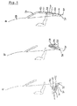
- figure 5 illustrating a fifth embodiment of the open roof construction in accordance with the present invention.
- a schematic side elevational view part of the vehicle body 18 is illustrated with a wind shield area 19 and a trunk area 24.
- a telescoping mechanism 4 with telescoping members 6-8 and roof panels 20-22 attached thereto is provided.
- a closed position figure 5a
- the leading roof panel 20 substantially abuts the wind shield area 19.
- embodiment according to figure 5 also may comprise two telescoping mechanisms 4 located substantially at the opposite longitudinal edges of said roof panels 20-22.
- each telescoping mechanism 4 moves in a fixed direction
- each telescoping mechanism 4 can move in a variable direction.
- each telescoping mechanism 4 is mounted for a rotation about an axis of rotation 23 extending substantially in a transverse direction (of the vehicle).
- the telescoping mechanism 4 is devised for firstly carrying out its translating telescoping movement (from figure 5a to figure 5b ) and next its rotation about said axis of rotation 23 (from figure 5b to figure 5c ).
- the telescoping mechanism 4 is devised for carrying out its telescoping movement and its rotation about said axis of rotation 23 at least partly simultaneously (and synchronised) or in any other order or combination of movements.
- the telescoping mechanism 4 is devised for, in their fully opened position, positioning the roof panels 20-22 in a trunk being part of the trunk area 24.
- the open roof construction according to the embodiment illustrated in figure 5 may comprise a roof opening with two opposite longitudinal edges which are defined by cant rails (not illustrated here) which are devised for maintaining their position along said longitudinal edges when the panels 20-22 move between the closed and opened positions or which are devised for moving along with the panels when these move between the closed and opened positions.
- cant rails again may comprise a number of cant rail members (not illustrated here) attached to longitudinal side edges of respective ones of the roof panels 20-22, which cant rail members then may be provided with cooperating connecting members for establishing a connection between successive cant rail members in the closed position of the roof panels.
- the roof panels 20-22 are attached to the respective telescoping members 6-8 in a manner to allow a change of the relative position between a roof panel and the corresponding telescoping member, for example through an axis of rotation (not illustrated here) extending substantially in a transverse direction.
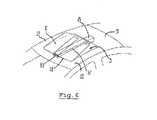
- figure 6 shows an embodiment of the open roof construction according to the invention in a situation similar to figure 16. In this case, however, only one roof panel 1' attached to a telescoping member 6' is provided.
Landscapes
- Engineering & Computer Science (AREA)
- Mechanical Engineering (AREA)
- Body Structure For Vehicles (AREA)
Abstract
Description
- The invention relates to an open roof construction for a vehicle, comprising a number of separate roof panels which are movable between a closed position for closing a roof opening of said vehicle and an opened position for at least partially freeing said roof opening.
- It is an object of the present invention to provide an improved open roof construction of the above type.
- Thus, in accordance with the present invention the open roof construction is characterized in that a telescoping mechanism is provided for moving said number of roof panels, substantially in a longitudinal direction of the vehicle, between the closed and opened positions, which telescoping mechanism is provided with a number of telescoping members which in a telescoping manner are movable relative to each other and wherein each panel is attached to and moved by a different one of said telescoping members.
- The use of such a telescoping mechanism, among others, offers the advantage that in the opened position of the roof panels a roof opening is obtained which, to a large amount, is free of obstacles and which, therefore, may be maximised (in correspondence with the constant demand for increasingly larger, unobstructed, roof openings in vehicles).
- It is noted, that the invention also relates to a case in which only one roof panel is present. In such a case, generally the telescoping mechanism comprises two telescoping members, of which one is attached to the roof panel and the other is attached to a stationary part of the vehicle (e.g. the vehicle body).
- In one embodiment, the open roof construction according to the present invention is provided with a single telescoping mechanism located substantially along a longitudinal centre line of said roof panels. Such an embodiment, for example, may be used when the dimensions (and, thus, weight) of the roof panels are moderate and sufficient stability may be obtained by just a single, central, telescoping mechanism.
- However, under certain circumstances (for example, when the dimensions, and thus weight, of the roof panels are more substantial) the open roof construction may be provided with two telescoping mechanisms located substantially at the opposite longitudinal edges of said roof panels.
- In one embodiment of the open roof construction according to present invention each telescoping mechanism moves in a fixed direction. Said fixed direction will be determined by the relative (translating) telescoping movement of the telescoping members of the telescoping mechanism.
- In an alternative embodiment however, which for example may be used in an open roof construction of which the roof panels have to describe a more complex (at least partially curved) track when moving between the closed and opened positions, each telescoping mechanism may move in a variable direction.
- For example, it is possible that each telescoping mechanism is mounted for a rotation about an axis of rotation extending substantially in a transverse direction. As a result the direction of the telescoping movement of the telescoping mechanism may be varied (at any desired stage of the movement, for example before or during said movement).
- In one embodiment, then, the telescoping mechanism is devised for carrying out its telescoping movement and its rotation about said axis of rotation substantially successively. That means that one of said movements (telescoping movement or rotation) substantially will be completed before the other one of said movements is carried out. For example, when moving the roof panels from the closed to the fully opened position initially a translating telescoping movement may be carried out, followed by a rotation of the telescoping mechanism.
- Alternatively, the telescoping mechanism may be devised for carrying out its telescoping movement and its rotation about said axis of rotation at least partly simultaneously. This means that a translating telescoping movement and said rotation at least partly are carried out at the same time.
- In yet another embodiment of the open roof construction according to the present invention, each telescoping mechanism is attached to the vehicle at a position behind the roof opening, as seen in the longitudinal direction of said vehicle, such that the panels, when moved to the fully opened position, are located substantially behind said roof opening. As a result the free roof opening, in the fully opened position of the roof panels, may be maximised.
- The open roof construction according to the present invention may be applied to a vehicle of the type having a rear trunk, in which case the telescoping mechanism may be devised for, in their fully opened position, positioning the panels in said trunk. It is noted, that especially in such a case the embodiment is favourable in which each telescoping mechanism can move in a variable direction (and, for example, may rotate around a transverse axis of rotation).
- In one embodiment of the open roof construction, the roof opening comprises two opposite longitudinal edges which are defined by cant rails which are devised for maintaining their position along said longitudinal edges when the panels move between the closed and opened positions. This means, that said cant rails will maintain their original position at opposite longitudinal edges of the roof opening (connecting a forward body part -e.g. the so called A-beam-of the vehicle with a rearward body part -e.g. the so called C-beam- when the roof panels are moved to an opened position and, thus, add to the overall constructional stability of the vehicle).
- However, as an alternative, it is possible that the roof opening comprises two opposite longitudinal edges which are defined by cant rails which are devised for moving along with the panels when these move between the closed and opened positions. Such an embodiment allows to offer the vehicle the appearance of a convertible when the roof panels have moved to the opened position.
- In such a case, each cant rail may comprise a number of cant rail members attached to longitudinal side edges of respective ones of the roof panels, which cant rail members are provided with cooperating connecting members for establishing a connection between successive cant rail members in the closed position of the roof panels. In the closed position of the roof panels the connecting members ensure that the cant rail members define rigid cant rails. When the roof panels have to be moved to the opened position, the connecting members will be disconnected from each other.
- Although it is conceivable that each roof panel is attached to a respective telescoping member in a rigid manner, in one embodiment of the open roof construction according to the present invention the roof panels are attached to the respective telescoping members in a manner to allow a change of the relative position between a roof panel and the corresponding telescoping member. This allows to achieve more complicated movements of the roof panels (for example to take into account space limitations).
- For example it is conceivable, that each roof panel is attached to a respective telescoping member through an axis of rotation extending substantially in a transverse direction. The rotation of a roof panel around such axis may be synchronised with the movement of the telescoping mechanism.
- It is noted, that the telescoping mechanism may be rectilinear or curved. The resulting translating movement then also will be according to a straight or curved line, respectively.
- Hereinafter the invention will be elucidated while referring to the drawings in which a number of embodiments of the open roof construction according the present invention are illustrated. In the drawings:
-
Figure 1 shows, in perspective and schematically, a first embodiment of the open roof construction according to the present invention, in a closed position, an intermediate position and an opened position; -
Figure 2 shows, in perspective and schematically, a second embodiment of the open roof construction according to the present invention, in a closed position, an intermediate position and an opened position; -
Figure 3 shows, in perspective and schematically, a third embodiment of the open roof construction according to the present invention, in a closed position and in an opened position; -
Figure 4 shows, in perspective and schematically, a fourth embodiment of the open roof construction according to the present invention, in a closed position and in an opened position; -
Figure 5 shows, in a side elevational view and schematically, a fifth embodiment of the open roof construction according to the present invention, in a closed position, an intermediate position and in an opened position; and -
Figure 6 shows, similar tofigure 1b , a sixth embodiment of the open roof construction according to the present invention. - Firstly referring to
figure 1 , a first embodiment of a roof construction for a vehicle is illustrated, comprising twoseparate roof panels figure 1a ) for closing a roof opening 3 of said vehicle and an opened position (figure 1c ) for at least partially freeing said roof opening. - A
telescoping mechanism 4 is provided for moving saidroof panels longitudinal direction 5 of the vehicle, between the closed and opened positions. Thetelescoping mechanism 4 is provided with a number of telescoping members 6-8 which in a telescoping manner are movable relative to each other. Afirst panel 1 is attached to and moved bytelescoping member 6, whereas asecond panel 2 is attached to and moved bytelescoping member 7. In the illustratedembodiment telescoping member 8 is attached to astationary roof part 9 at a position behind theroof opening 3, as seen in the longitudinal direction of said vehicle, such that thepanels - As appears clearly from
figure 1 , the open roof construction is provided with asingle telescoping mechanism 4 located substantially along a longitudinal centre line of saidroof panels telescoping mechanism 4 moves in a fixed direction according to a translational movement, and thus its telescopingmember 8 may be attached to thestationary roof part 9 in a fixed manner. - The
roof panels respective telescoping members roof panel respective telescoping member figure 1b only) extending substantially in a transverse direction (and in the illustrated embodiment in the immediate vicinity of a leadingedge 11 of the respective roof panel). - In the embodiment of
figure 1 the rotation of thepanels respective axis 10 and the telescoping (translating) movement of thetelescoping mechanism 4 are synchronised in such a manner that firstly a rotation of thepanels figure 1a to figure 1b ) and next a translation (fromfigure 1b to figure 1c ). It is conceivable, however, that such movements occur at least partly simultaneously and/or in a different order. - Finally
figure 1c shows that theroof opening 3 comprises two opposite longitudinal edges which are defined bycant rails 12 which are devised for maintaining their position along said longitudinal edges when thepanels -
Figure 2 shows (again in three successive positions) a second embodiment of the open roof construction according to the present invention which closely resembles the embodiment according tofigure 1 and in which like parts are indicated by like reference numbers. The only difference with the previous embodiment is that this second embodiment comprises twotelescoping mechanisms 4 located substantially at the opposite longitudinal edges of theroof panels figure 1 and will not be repeated here. - The third embodiment shown in
figure 3 comprises a number of parts similar tofigure 1 and thus provided with like reference numbers. In this case, however, theroof opening 3 comprises two opposite longitudinal edges which are defined by cant rails 12' which are devised for moving along with thepanels cant rail members roof panels 1,2 (and stationarycant rail members figure 3b ) for establishing a connection between successive cant rail members 13-16 in the closed position of the panel members. -
Figure 4 shows a fourth embodiment which closely resembles the embodiment according tofigure 3 and in which like parts are indicated by like reference numbers. The only difference with the previous embodiment is that this second embodiment again comprises twotelescoping mechanisms 4 located substantially at the opposite longitudinal edges of theroof panels - Next, reference is made to
figure 5 illustrating a fifth embodiment of the open roof construction in accordance with the present invention. In a schematic side elevational view part of thevehicle body 18 is illustrated with awind shield area 19 and atrunk area 24. Atelescoping mechanism 4 with telescoping members 6-8 and roof panels 20-22 attached thereto is provided. In a closed position (figure 5a ) the leadingroof panel 20 substantially abuts thewind shield area 19. - It is noted that the embodiment according to
figure 5 also may comprise twotelescoping mechanisms 4 located substantially at the opposite longitudinal edges of said roof panels 20-22. - Whereas in the embodiments of the open roof construction according to
figures 1-4 , eachtelescoping mechanism 4 moves in a fixed direction, in the present embodiment eachtelescoping mechanism 4 can move in a variable direction. As represented schematically, eachtelescoping mechanism 4 is mounted for a rotation about an axis ofrotation 23 extending substantially in a transverse direction (of the vehicle). - In the illustrated embodiment of the open roof construction the
telescoping mechanism 4 is devised for firstly carrying out its translating telescoping movement (fromfigure 5a to figure 5b ) and next its rotation about said axis of rotation 23 (fromfigure 5b to figure 5c ). - It is conceivable, however, that the
telescoping mechanism 4 is devised for carrying out its telescoping movement and its rotation about said axis ofrotation 23 at least partly simultaneously (and synchronised) or in any other order or combination of movements. - In the embodiment of the open roof construction according to
figure 5 , thetelescoping mechanism 4 is devised for, in their fully opened position, positioning the roof panels 20-22 in a trunk being part of thetrunk area 24. - In accordance with some aspects of the previous embodiments, the open roof construction according to the embodiment illustrated in
figure 5 may comprise a roof opening with two opposite longitudinal edges which are defined by cant rails (not illustrated here) which are devised for maintaining their position along said longitudinal edges when the panels 20-22 move between the closed and opened positions or which are devised for moving along with the panels when these move between the closed and opened positions. In the latter case such cant rails again may comprise a number of cant rail members (not illustrated here) attached to longitudinal side edges of respective ones of the roof panels 20-22, which cant rail members then may be provided with cooperating connecting members for establishing a connection between successive cant rail members in the closed position of the roof panels. - In the embodiment according to
figure 5 the roof panels 20-22 are attached to the respective telescoping members 6-8 in a manner to allow a change of the relative position between a roof panel and the corresponding telescoping member, for example through an axis of rotation (not illustrated here) extending substantially in a transverse direction. - Finally,
figure 6 shows an embodiment of the open roof construction according to the invention in a situation similar to figure 16. In this case, however, only one roof panel 1' attached to a telescoping member 6' is provided. - The invention is not limited to the embodiments described before which may be varied widely within the scope of the invention as defined by the appending claims.
Claims (15)
- Open roof construction for a vehicle, comprising a number of separate roof panels (1,2:20-22) which are movable between a closed position for closing a roof opening (3) of said vehicle and an opened position for at least partially freeing said roof opening, characterized in that a telescoping mechanism (4) is provided for moving said number of roof panels (1,2;20-22), substantially in a longitudinal direction of the vehicle, between the closed and opened positions, which telescoping mechanism (4) is provided with a number of telescoping members (6-8) which in a telescoping manner are movable relative to each other and wherein each panel (1,2;20-22) is attached to and moved by a different one of said telescoping members (6-8).
- Open roof construction according to claim 1, provided with a single telescoping mechanism (4) located substantially along a longitudinal centre line of said roof panels (1,2;20-22).
- Open roof construction according to claim 1, provided with two telescoping mechanism (4) located substantially at the opposite longitudinal edges of said roof panels (1,2;20-22).
- Open roof construction according to any of the previous claims, wherein each telescoping mechanism (4) moves in a fixed direction.
- Open roof construction according to any of the claims 1-3, wherein each telescoping mechanism (4) moves in a variable direction.
- Open roof construction according to claim 5, wherein each telescoping mechanism (4) is mounted for a rotation about an axis of rotation (23) extending substantially in a transverse direction.
- Open roof construction according to claim 6, wherein the telescoping mechanism (4) is devised for carrying out its telescoping movement and its rotation about said axis of rotation (23) substantially successively.
- Open roof construction according to claim 6, wherein the telescoping mechanism (4) is devised for carrying out its telescoping movement and its rotation about said axis of rotation (23) at least partly simultaneously.
- Open roof construction according to any of the previous claims, wherein each telescoping mechanism (4) is attached to the vehicle at a position behind the roof opening (3), as seen in the longitudinal direction of said vehicle, such that the panels (1,2:20-22), when moved to the fully opened position, are located substantially behind said roof opening.
- Open roof construction according to any of the previous claims for a vehicle of the type having a rear trunk (24), wherein the telescoping mechanism (4) is devised for positioning the panels (1,2;20-22) in their fully opened position in said trunk.
- Open roof construction according to any of the previous claims, wherein the roof opening (3) comprises two opposite longitudinal edges which are defined by cant rails (12) which are devised for maintaining their position along said longitudinal edges when the panels (1,2;20-22) move between the closed and opened positions.
- Open roof construction according to any of the claims 1-10, wherein the roof opening comprises two opposite longitudinal edges which are defined by cant rails (1-2') which are devised for moving along with the panels (1,2;20-22) when these move between the closed and opened positions.
- Open roof construction according to claim 12,
wherein each cant rail (1-2') comprises a number of cant rail members (13,14) attached to longitudinal side edges of respective ones of the roof panels (1,2;20-22), which cant rail members are provided with cooperating connecting members (17) for, in the closed position of the roof panels (1,2;20-22), establishing a connection between successive cant rail members (13-16). - Open roof construction according to any of the previous claims, wherein the roof panels (1,2;20-22) are attached to the respective telescoping members (6-8) in a manner to allow a change of the relative position between a roof panel and the corresponding telescoping member.
- Open roof construction according to claim 14, wherein each roof panel (1,2;20-22) is attached to a respective telescoping member (6-8) through an axis of rotation (10) extending substantially in a transverse direction.
Priority Applications (4)
| Application Number | Priority Date | Filing Date | Title |
|---|---|---|---|
| EP12161182.6A EP2644422B1 (en) | 2012-03-26 | 2012-03-26 | Open roof construction for a vehicle |
| PCT/EP2013/054511 WO2013143815A1 (en) | 2012-03-26 | 2013-03-06 | Open roof construction for a vehicle |
| US14/387,166 US20150048645A1 (en) | 2012-03-26 | 2013-03-06 | Open roof construction for a vehicle |
| CN201380022064.5A CN104245378B (en) | 2012-03-26 | 2013-03-06 | Open roof construction for a vehicle |
Applications Claiming Priority (1)
| Application Number | Priority Date | Filing Date | Title |
|---|---|---|---|
| EP12161182.6A EP2644422B1 (en) | 2012-03-26 | 2012-03-26 | Open roof construction for a vehicle |
Publications (2)
| Publication Number | Publication Date |
|---|---|
| EP2644422A1 true EP2644422A1 (en) | 2013-10-02 |
| EP2644422B1 EP2644422B1 (en) | 2014-10-15 |
Family
ID=47790257
Family Applications (1)
| Application Number | Title | Priority Date | Filing Date |
|---|---|---|---|
| EP12161182.6A Active EP2644422B1 (en) | 2012-03-26 | 2012-03-26 | Open roof construction for a vehicle |
Country Status (4)
| Country | Link |
|---|---|
| US (1) | US20150048645A1 (en) |
| EP (1) | EP2644422B1 (en) |
| CN (1) | CN104245378B (en) |
| WO (1) | WO2013143815A1 (en) |
Cited By (1)
| Publication number | Priority date | Publication date | Assignee | Title |
|---|---|---|---|---|
| CN110356209A (en) * | 2019-07-12 | 2019-10-22 | 重庆长安汽车股份有限公司 | A kind of panorama type power sunroof |
Families Citing this family (1)
| Publication number | Priority date | Publication date | Assignee | Title |
|---|---|---|---|---|
| US10202026B1 (en) * | 2017-08-10 | 2019-02-12 | Ford Global Technologies, Llc | Multi-panel moonroof and method of using the same |
Citations (3)
| Publication number | Priority date | Publication date | Assignee | Title |
|---|---|---|---|---|
| GB923270A (en) * | 1960-10-28 | 1963-04-10 | Webasto Werk Baier Kg W | A slidable roof assembly on a vehicle |
| FR2808482A1 (en) * | 2000-05-05 | 2001-11-09 | France Design | CONVERTIBLE ROOF FOR VEHICLE, PARTICULARLY OF THE TYPE FOR TRANSFORMING A CUT INTO CONVERTIBLE AND VICE-VERSA |
| EP1454783A1 (en) * | 2003-03-07 | 2004-09-08 | ArvinMeritor GmbH | Vehicle roof with a serie of lamellar plates |
Family Cites Families (9)
| Publication number | Priority date | Publication date | Assignee | Title |
|---|---|---|---|---|
| JPH0790695B2 (en) * | 1989-09-26 | 1995-10-04 | 株式会社大井製作所 | Roof door opening and closing device |
| DE19542884C1 (en) * | 1995-11-17 | 1996-12-12 | Webasto Karosseriesysteme | Vehicle roof with extensible slats |
| DE19608916C1 (en) * | 1996-03-07 | 1997-04-17 | Webasto Karosseriesysteme | Vehicle roof in at least two parts |
| DE19634507C1 (en) * | 1996-08-27 | 1998-01-22 | Daimler Benz Ag | Roof for convertible sports car |
| NL1006925C2 (en) * | 1997-09-03 | 1999-03-04 | Inalfa Ind Bv | Method for opening and closing an open roof construction of a vehicle with an opening in the fixed roof; as well as such an open roof construction. |
| DE19835535C1 (en) * | 1998-08-06 | 1999-10-07 | Webasto Karosseriesysteme | Road vehicle roof with sequence of cover components formed as lamellas |
| DE10154777A1 (en) * | 2001-11-08 | 2003-05-22 | Arvinmeritor Gmbh | Sliding system for closing and opening a roof opening |
| JP2008221900A (en) * | 2007-03-08 | 2008-09-25 | Yachiyo Industry Co Ltd | Sunroof device for vehicle |
| EP2017108B1 (en) * | 2007-07-16 | 2011-03-30 | Inalfa Roof Systems Group B.V. | Open roof construction for a vehicle |
-
2012
- 2012-03-26 EP EP12161182.6A patent/EP2644422B1/en active Active
-
2013
- 2013-03-06 CN CN201380022064.5A patent/CN104245378B/en active Active
- 2013-03-06 US US14/387,166 patent/US20150048645A1/en not_active Abandoned
- 2013-03-06 WO PCT/EP2013/054511 patent/WO2013143815A1/en not_active Ceased
Patent Citations (3)
| Publication number | Priority date | Publication date | Assignee | Title |
|---|---|---|---|---|
| GB923270A (en) * | 1960-10-28 | 1963-04-10 | Webasto Werk Baier Kg W | A slidable roof assembly on a vehicle |
| FR2808482A1 (en) * | 2000-05-05 | 2001-11-09 | France Design | CONVERTIBLE ROOF FOR VEHICLE, PARTICULARLY OF THE TYPE FOR TRANSFORMING A CUT INTO CONVERTIBLE AND VICE-VERSA |
| EP1454783A1 (en) * | 2003-03-07 | 2004-09-08 | ArvinMeritor GmbH | Vehicle roof with a serie of lamellar plates |
Cited By (1)
| Publication number | Priority date | Publication date | Assignee | Title |
|---|---|---|---|---|
| CN110356209A (en) * | 2019-07-12 | 2019-10-22 | 重庆长安汽车股份有限公司 | A kind of panorama type power sunroof |
Also Published As
| Publication number | Publication date |
|---|---|
| WO2013143815A1 (en) | 2013-10-03 |
| EP2644422B1 (en) | 2014-10-15 |
| US20150048645A1 (en) | 2015-02-19 |
| CN104245378B (en) | 2017-02-22 |
| CN104245378A (en) | 2014-12-24 |
Similar Documents
| Publication | Publication Date | Title |
|---|---|---|
| DE10134370B4 (en) | Covering device for a convertible top compartment | |
| US6502892B2 (en) | Convertible motor vehicle roof | |
| DE10028405B4 (en) | Boot lid assembly for a vehicle with a retractable top | |
| EP1308333A1 (en) | Storable roof for convertible vehicle | |
| DE102012025566A1 (en) | Automotive body | |
| DE10234351A1 (en) | Cabriolet with retractable folding roof | |
| EP2644422B1 (en) | Open roof construction for a vehicle | |
| IT9021536A1 (en) | CONVERTIBLE CAR | |
| DE10249299B4 (en) | Storage compartment cover of a convertible | |
| DE19932502A1 (en) | Cover device for a convertible top compartment | |
| DE10026095B4 (en) | Hard top vehicle roof adjustable between a closed position and an open position | |
| DE102012025071A1 (en) | Glazed roof for e.g. motor vehicle, has shuttle controlling displacement of movable deflector between retracted position corresponding to closed position of movable panel and deflection position corresponding to open position of panel | |
| EP1842709A2 (en) | Adjustable vehicle roof | |
| US20070090664A1 (en) | Hardtop vehicle roof with external roof kinematic system | |
| CN105235483A (en) | Roof device suitable for cabriolet | |
| DE102014216369A1 (en) | Hinge arrangement for a door of a motor vehicle | |
| DE102006028078B4 (en) | Openable vehicle roof with fin top and operating method for this | |
| DE102012113232B4 (en) | Cabriolet vehicle with a rear cover and a hood | |
| DE102013114964B4 (en) | Soft-top convertible top | |
| DE102006055276B4 (en) | Moving roof of a construction of a motor vehicle | |
| EP2377708B1 (en) | Soft top for a convertible vehicle | |
| DE102014203581B4 (en) | Motor vehicle roof | |
| US9827837B2 (en) | Moveable panel system for non-parallel tracks | |
| DE102010012121A1 (en) | Separating device for separating baggage compartment from bonnet receiving space in rear room of e.g. cabriolet car, has pivot axes that are movable along guide link when rear and front bonnets are adjusted | |
| DE102014213730B3 (en) | roof |
Legal Events
| Date | Code | Title | Description |
|---|---|---|---|
| PUAI | Public reference made under article 153(3) epc to a published international application that has entered the european phase |
Free format text: ORIGINAL CODE: 0009012 |
|
| AK | Designated contracting states |
Kind code of ref document: A1 Designated state(s): AL AT BE BG CH CY CZ DE DK EE ES FI FR GB GR HR HU IE IS IT LI LT LU LV MC MK MT NL NO PL PT RO RS SE SI SK SM TR |
|
| AX | Request for extension of the european patent |
Extension state: BA ME |
|
| 17P | Request for examination filed |
Effective date: 20140320 |
|
| RBV | Designated contracting states (corrected) |
Designated state(s): AL AT BE BG CH CY CZ DE DK EE ES FI FR GB GR HR HU IE IS IT LI LT LU LV MC MK MT NL NO PL PT RO RS SE SI SK SM TR |
|
| GRAP | Despatch of communication of intention to grant a patent |
Free format text: ORIGINAL CODE: EPIDOSNIGR1 |
|
| INTG | Intention to grant announced |
Effective date: 20140603 |
|
| GRAS | Grant fee paid |
Free format text: ORIGINAL CODE: EPIDOSNIGR3 |
|
| GRAA | (expected) grant |
Free format text: ORIGINAL CODE: 0009210 |
|
| AK | Designated contracting states |
Kind code of ref document: B1 Designated state(s): AL AT BE BG CH CY CZ DE DK EE ES FI FR GB GR HR HU IE IS IT LI LT LU LV MC MK MT NL NO PL PT RO RS SE SI SK SM TR |
|
| REG | Reference to a national code |
Ref country code: CH Ref legal event code: EP Ref country code: GB Ref legal event code: FG4D |
|
| REG | Reference to a national code |
Ref country code: IE Ref legal event code: FG4D |
|
| REG | Reference to a national code |
Ref country code: AT Ref legal event code: REF Ref document number: 691471 Country of ref document: AT Kind code of ref document: T Effective date: 20141115 |
|
| REG | Reference to a national code |
Ref country code: DE Ref legal event code: R096 Ref document number: 602012003382 Country of ref document: DE Effective date: 20141127 |
|
| REG | Reference to a national code |
Ref country code: NL Ref legal event code: VDEP Effective date: 20141015 |
|
| REG | Reference to a national code |
Ref country code: AT Ref legal event code: MK05 Ref document number: 691471 Country of ref document: AT Kind code of ref document: T Effective date: 20141015 |
|
| REG | Reference to a national code |
Ref country code: FR Ref legal event code: PLFP Year of fee payment: 4 |
|
| REG | Reference to a national code |
Ref country code: LT Ref legal event code: MG4D |
|
| PG25 | Lapsed in a contracting state [announced via postgrant information from national office to epo] |
Ref country code: NL Free format text: LAPSE BECAUSE OF FAILURE TO SUBMIT A TRANSLATION OF THE DESCRIPTION OR TO PAY THE FEE WITHIN THE PRESCRIBED TIME-LIMIT Effective date: 20141015 |
|
| PG25 | Lapsed in a contracting state [announced via postgrant information from national office to epo] |
Ref country code: LT Free format text: LAPSE BECAUSE OF FAILURE TO SUBMIT A TRANSLATION OF THE DESCRIPTION OR TO PAY THE FEE WITHIN THE PRESCRIBED TIME-LIMIT Effective date: 20141015 Ref country code: IS Free format text: LAPSE BECAUSE OF FAILURE TO SUBMIT A TRANSLATION OF THE DESCRIPTION OR TO PAY THE FEE WITHIN THE PRESCRIBED TIME-LIMIT Effective date: 20150215 Ref country code: PT Free format text: LAPSE BECAUSE OF FAILURE TO SUBMIT A TRANSLATION OF THE DESCRIPTION OR TO PAY THE FEE WITHIN THE PRESCRIBED TIME-LIMIT Effective date: 20150216 Ref country code: NO Free format text: LAPSE BECAUSE OF FAILURE TO SUBMIT A TRANSLATION OF THE DESCRIPTION OR TO PAY THE FEE WITHIN THE PRESCRIBED TIME-LIMIT Effective date: 20150115 Ref country code: FI Free format text: LAPSE BECAUSE OF FAILURE TO SUBMIT A TRANSLATION OF THE DESCRIPTION OR TO PAY THE FEE WITHIN THE PRESCRIBED TIME-LIMIT Effective date: 20141015 Ref country code: ES Free format text: LAPSE BECAUSE OF FAILURE TO SUBMIT A TRANSLATION OF THE DESCRIPTION OR TO PAY THE FEE WITHIN THE PRESCRIBED TIME-LIMIT Effective date: 20141015 |
|
| PG25 | Lapsed in a contracting state [announced via postgrant information from national office to epo] |
Ref country code: CY Free format text: LAPSE BECAUSE OF FAILURE TO SUBMIT A TRANSLATION OF THE DESCRIPTION OR TO PAY THE FEE WITHIN THE PRESCRIBED TIME-LIMIT Effective date: 20141015 Ref country code: SE Free format text: LAPSE BECAUSE OF FAILURE TO SUBMIT A TRANSLATION OF THE DESCRIPTION OR TO PAY THE FEE WITHIN THE PRESCRIBED TIME-LIMIT Effective date: 20141015 Ref country code: GR Free format text: LAPSE BECAUSE OF FAILURE TO SUBMIT A TRANSLATION OF THE DESCRIPTION OR TO PAY THE FEE WITHIN THE PRESCRIBED TIME-LIMIT Effective date: 20150116 Ref country code: HR Free format text: LAPSE BECAUSE OF FAILURE TO SUBMIT A TRANSLATION OF THE DESCRIPTION OR TO PAY THE FEE WITHIN THE PRESCRIBED TIME-LIMIT Effective date: 20141015 Ref country code: AT Free format text: LAPSE BECAUSE OF FAILURE TO SUBMIT A TRANSLATION OF THE DESCRIPTION OR TO PAY THE FEE WITHIN THE PRESCRIBED TIME-LIMIT Effective date: 20141015 Ref country code: LV Free format text: LAPSE BECAUSE OF FAILURE TO SUBMIT A TRANSLATION OF THE DESCRIPTION OR TO PAY THE FEE WITHIN THE PRESCRIBED TIME-LIMIT Effective date: 20141015 Ref country code: PL Free format text: LAPSE BECAUSE OF FAILURE TO SUBMIT A TRANSLATION OF THE DESCRIPTION OR TO PAY THE FEE WITHIN THE PRESCRIBED TIME-LIMIT Effective date: 20141015 Ref country code: RS Free format text: LAPSE BECAUSE OF FAILURE TO SUBMIT A TRANSLATION OF THE DESCRIPTION OR TO PAY THE FEE WITHIN THE PRESCRIBED TIME-LIMIT Effective date: 20141015 |
|
| REG | Reference to a national code |
Ref country code: DE Ref legal event code: R097 Ref document number: 602012003382 Country of ref document: DE |
|
| PG25 | Lapsed in a contracting state [announced via postgrant information from national office to epo] |
Ref country code: DK Free format text: LAPSE BECAUSE OF FAILURE TO SUBMIT A TRANSLATION OF THE DESCRIPTION OR TO PAY THE FEE WITHIN THE PRESCRIBED TIME-LIMIT Effective date: 20141015 Ref country code: RO Free format text: LAPSE BECAUSE OF FAILURE TO SUBMIT A TRANSLATION OF THE DESCRIPTION OR TO PAY THE FEE WITHIN THE PRESCRIBED TIME-LIMIT Effective date: 20141015 Ref country code: EE Free format text: LAPSE BECAUSE OF FAILURE TO SUBMIT A TRANSLATION OF THE DESCRIPTION OR TO PAY THE FEE WITHIN THE PRESCRIBED TIME-LIMIT Effective date: 20141015 Ref country code: CZ Free format text: LAPSE BECAUSE OF FAILURE TO SUBMIT A TRANSLATION OF THE DESCRIPTION OR TO PAY THE FEE WITHIN THE PRESCRIBED TIME-LIMIT Effective date: 20141015 Ref country code: SK Free format text: LAPSE BECAUSE OF FAILURE TO SUBMIT A TRANSLATION OF THE DESCRIPTION OR TO PAY THE FEE WITHIN THE PRESCRIBED TIME-LIMIT Effective date: 20141015 |
|
| PLBE | No opposition filed within time limit |
Free format text: ORIGINAL CODE: 0009261 |
|
| STAA | Information on the status of an ep patent application or granted ep patent |
Free format text: STATUS: NO OPPOSITION FILED WITHIN TIME LIMIT |
|
| PG25 | Lapsed in a contracting state [announced via postgrant information from national office to epo] |
Ref country code: IT Free format text: LAPSE BECAUSE OF FAILURE TO SUBMIT A TRANSLATION OF THE DESCRIPTION OR TO PAY THE FEE WITHIN THE PRESCRIBED TIME-LIMIT Effective date: 20141015 |
|
| 26N | No opposition filed |
Effective date: 20150716 |
|
| PG25 | Lapsed in a contracting state [announced via postgrant information from national office to epo] |
Ref country code: MC Free format text: LAPSE BECAUSE OF FAILURE TO SUBMIT A TRANSLATION OF THE DESCRIPTION OR TO PAY THE FEE WITHIN THE PRESCRIBED TIME-LIMIT Effective date: 20141015 Ref country code: LU Free format text: LAPSE BECAUSE OF FAILURE TO SUBMIT A TRANSLATION OF THE DESCRIPTION OR TO PAY THE FEE WITHIN THE PRESCRIBED TIME-LIMIT Effective date: 20150326 |
|
| REG | Reference to a national code |
Ref country code: CH Ref legal event code: PL |
|
| REG | Reference to a national code |
Ref country code: IE Ref legal event code: MM4A |
|
| PG25 | Lapsed in a contracting state [announced via postgrant information from national office to epo] |
Ref country code: LI Free format text: LAPSE BECAUSE OF NON-PAYMENT OF DUE FEES Effective date: 20150331 Ref country code: IE Free format text: LAPSE BECAUSE OF NON-PAYMENT OF DUE FEES Effective date: 20150326 Ref country code: CH Free format text: LAPSE BECAUSE OF NON-PAYMENT OF DUE FEES Effective date: 20150331 |
|
| PG25 | Lapsed in a contracting state [announced via postgrant information from national office to epo] |
Ref country code: SI Free format text: LAPSE BECAUSE OF FAILURE TO SUBMIT A TRANSLATION OF THE DESCRIPTION OR TO PAY THE FEE WITHIN THE PRESCRIBED TIME-LIMIT Effective date: 20141015 |
|
| REG | Reference to a national code |
Ref country code: FR Ref legal event code: PLFP Year of fee payment: 5 |
|
| PG25 | Lapsed in a contracting state [announced via postgrant information from national office to epo] |
Ref country code: MT Free format text: LAPSE BECAUSE OF FAILURE TO SUBMIT A TRANSLATION OF THE DESCRIPTION OR TO PAY THE FEE WITHIN THE PRESCRIBED TIME-LIMIT Effective date: 20141015 |
|
| REG | Reference to a national code |
Ref country code: FR Ref legal event code: PLFP Year of fee payment: 6 |
|
| PG25 | Lapsed in a contracting state [announced via postgrant information from national office to epo] |
Ref country code: BG Free format text: LAPSE BECAUSE OF FAILURE TO SUBMIT A TRANSLATION OF THE DESCRIPTION OR TO PAY THE FEE WITHIN THE PRESCRIBED TIME-LIMIT Effective date: 20141015 Ref country code: HU Free format text: LAPSE BECAUSE OF FAILURE TO SUBMIT A TRANSLATION OF THE DESCRIPTION OR TO PAY THE FEE WITHIN THE PRESCRIBED TIME-LIMIT; INVALID AB INITIO Effective date: 20120326 Ref country code: SM Free format text: LAPSE BECAUSE OF FAILURE TO SUBMIT A TRANSLATION OF THE DESCRIPTION OR TO PAY THE FEE WITHIN THE PRESCRIBED TIME-LIMIT Effective date: 20141015 |
|
| PG25 | Lapsed in a contracting state [announced via postgrant information from national office to epo] |
Ref country code: TR Free format text: LAPSE BECAUSE OF FAILURE TO SUBMIT A TRANSLATION OF THE DESCRIPTION OR TO PAY THE FEE WITHIN THE PRESCRIBED TIME-LIMIT Effective date: 20141015 |
|
| PG25 | Lapsed in a contracting state [announced via postgrant information from national office to epo] |
Ref country code: BE Free format text: LAPSE BECAUSE OF FAILURE TO SUBMIT A TRANSLATION OF THE DESCRIPTION OR TO PAY THE FEE WITHIN THE PRESCRIBED TIME-LIMIT Effective date: 20141015 |
|
| REG | Reference to a national code |
Ref country code: FR Ref legal event code: PLFP Year of fee payment: 7 |
|
| PG25 | Lapsed in a contracting state [announced via postgrant information from national office to epo] |
Ref country code: MK Free format text: LAPSE BECAUSE OF FAILURE TO SUBMIT A TRANSLATION OF THE DESCRIPTION OR TO PAY THE FEE WITHIN THE PRESCRIBED TIME-LIMIT Effective date: 20141015 |
|
| PG25 | Lapsed in a contracting state [announced via postgrant information from national office to epo] |
Ref country code: AL Free format text: LAPSE BECAUSE OF FAILURE TO SUBMIT A TRANSLATION OF THE DESCRIPTION OR TO PAY THE FEE WITHIN THE PRESCRIBED TIME-LIMIT Effective date: 20141015 |
|
| PGFP | Annual fee paid to national office [announced via postgrant information from national office to epo] |
Ref country code: DE Payment date: 20250327 Year of fee payment: 14 |
|
| PGFP | Annual fee paid to national office [announced via postgrant information from national office to epo] |
Ref country code: FR Payment date: 20250325 Year of fee payment: 14 |
|
| PGFP | Annual fee paid to national office [announced via postgrant information from national office to epo] |
Ref country code: GB Payment date: 20250327 Year of fee payment: 14 |