EP2017108B1 - Open roof construction for a vehicle - Google Patents
Open roof construction for a vehicle Download PDFInfo
- Publication number
- EP2017108B1 EP2017108B1 EP07112527A EP07112527A EP2017108B1 EP 2017108 B1 EP2017108 B1 EP 2017108B1 EP 07112527 A EP07112527 A EP 07112527A EP 07112527 A EP07112527 A EP 07112527A EP 2017108 B1 EP2017108 B1 EP 2017108B1
- Authority
- EP
- European Patent Office
- Prior art keywords
- slide
- locking
- panel
- stationary
- roof construction
- Prior art date
- Legal status (The legal status is an assumption and is not a legal conclusion. Google has not performed a legal analysis and makes no representation as to the accuracy of the status listed.)
- Active
Links
- 238000010276 construction Methods 0.000 title claims description 32
- 230000007246 mechanism Effects 0.000 description 2
- 230000001133 acceleration Effects 0.000 description 1
- 238000006073 displacement reaction Methods 0.000 description 1
- 230000035939 shock Effects 0.000 description 1
- 230000007704 transition Effects 0.000 description 1
Images


Classifications
-
- B—PERFORMING OPERATIONS; TRANSPORTING
- B60—VEHICLES IN GENERAL
- B60J—WINDOWS, WINDSCREENS, NON-FIXED ROOFS, DOORS, OR SIMILAR DEVICES FOR VEHICLES; REMOVABLE EXTERNAL PROTECTIVE COVERINGS SPECIALLY ADAPTED FOR VEHICLES
- B60J7/00—Non-fixed roofs; Roofs with movable panels, e.g. rotary sunroofs
- B60J7/02—Non-fixed roofs; Roofs with movable panels, e.g. rotary sunroofs of sliding type, e.g. comprising guide shoes
- B60J7/024—Non-fixed roofs; Roofs with movable panels, e.g. rotary sunroofs of sliding type, e.g. comprising guide shoes characterised by the height regulating mechanism of the sliding panel
-
- B—PERFORMING OPERATIONS; TRANSPORTING
- B60—VEHICLES IN GENERAL
- B60J—WINDOWS, WINDSCREENS, NON-FIXED ROOFS, DOORS, OR SIMILAR DEVICES FOR VEHICLES; REMOVABLE EXTERNAL PROTECTIVE COVERINGS SPECIALLY ADAPTED FOR VEHICLES
- B60J7/00—Non-fixed roofs; Roofs with movable panels, e.g. rotary sunroofs
- B60J7/02—Non-fixed roofs; Roofs with movable panels, e.g. rotary sunroofs of sliding type, e.g. comprising guide shoes
- B60J7/04—Non-fixed roofs; Roofs with movable panels, e.g. rotary sunroofs of sliding type, e.g. comprising guide shoes with rigid plate-like element or elements, e.g. open roofs with harmonica-type folding rigid panels
- B60J7/05—Non-fixed roofs; Roofs with movable panels, e.g. rotary sunroofs of sliding type, e.g. comprising guide shoes with rigid plate-like element or elements, e.g. open roofs with harmonica-type folding rigid panels pivoting upwardly to vent mode and moving downward before sliding to fully open mode
Definitions
- the invention relates to an open roof construction for a vehicle, comprising a roof opening defined in a stationary roof part and a movable panel for opening and closing said roof opening, with a slide which is movable along a stationary slide guide and which is provided with panel engagement means cooperating with a panel curve of the movable panel, wherein a movement of the slide is capable of generating a tilting and/or sliding movement of the panel, as known from EP-A-1 500 539 .
- the movement of the slide basically is responsible for the movements of the movable panel (i.e. tilting and/or sliding movements of the panel).
- the movable panel i.e. tilting and/or sliding movements of the panel.
- an open roof construction of the type referred to above which is characterised by a locking lever which by means of a hinge point is connected to the panel and which is provided firstly with slide engagement means cooperating with a slide curve of the slide, secondly with guide means cooperating with a stationary lever guide and thirdly with a locking member cooperating with a stationary locking guide, such that in a first position of the slide the locking member is housed in a first stationary locking guide part preventing a translational movement of the locking lever and panel connected therewith and in a second position of the slide the locking member is housed in a second stationary locking guide part allowing a translational movement of the locking lever, and thus of the panel connected therewith at the hinge point.
- the open roof construction in accordance with the present invention allows to obtain the desired movements of the movable panel with a minimum of parts.
- the position of the locking lever basically defines two situations.
- a situation (locking member positioned in the first stationary locking guide part) in which a translational movement of the locking lever (and thus of the panel connected therewith at the hinge point) is prevented, but in which the moveable panel can be tilted to a tilt position
- a situation (locking member positioned in the second stationery locking guide part) in which such a translational movement (possibly in combination with a tilting movement of the movable panel) is allowed.
- the movement of the locking lever is generated automatically by the sliding movement of the slide, and no complicated additional mechanisms are necessary.
- the present open roof construction provides a total design freedom of the movement of the panel and specifically the leading edge thereof. As a result shocks and clicks as a result of excessive or uncontrolled accelerations can be avoided, leading to smoother movements of the construction parts.
- the open roof construction for a vehicle in accordance with the present invention comprises a roof opening 1 defined in a stationary roof part 2 and a movable panel 3 for opening and closing said roof opening (for some of these elements reference is made to figures 3 until 7).
- a slide 4 is illustrated which is movable along a stationary slide guide 5 (see figure 3 ).
- the movement of the slide 4 may be obtained by drive means 6, for example a drive cable known per se.
- the slide 4 may be provided with guide shoes 7 cooperating with the stationary slide guide 5.
- the slide 4 comprises panel engagement means 8 for cooperation with a panel curve 9 of the movable panel.
- said panel engagement means 8 are defined by a T-shaped recess
- the panel curve 9 is defined by a correspondingly shaped longitudinal T-shaped member being part of a bracket 10 which, in a manner not illustrated in detail, is connected to the movable panel 3.
- the slide 4 further comprises a slide curve 11 which, in the embodiment illustrated here, has an inclined extension, as will be elucidated below.
- the open roof construction further comprises a locking lever 12 which by means of a hinge pin 13 can be connected to a corresponding hinge point 14 on the (bracket of the) panel 3.
- the locking lever 12 is constructed as a member having a U-shaped cross section with two distanced webs 15 and 16 defining therebetween a gap 17 for at least partially receiving a part of the (bracket 10 of the) panel 3.
- the locking lever further is provided with a slide engagement means 18, in the illustrated embodiment a pin, which will cooperate with the slide curve 11 of the slide 4.
- the locking lever 12 comprises guide means 19 cooperating with a stationary lever guide 20 (illustrated in figure 3 ) and a locking member 21 cooperating with a stationary locking guide 22.
- Figure 2 shows the parts represented in figure 1 in an assembled position, in which a connection between the locking lever 12 and bracket 10 (and thus panel 3) is defined by the hinge pin 13 (and hinge point 14, not visible here), and wherein the T-shaped recess 8 receives the T-shaped member 9. Further, in this position the pin 18 (not visible here) is received in the slide curve 11 and the locking member 21 (neither visible here) is received in the stationary locking guide 22.
- Figure 3 shows schematically the relative positions and cooperation between the respective parts of the open roof construction in accordance with the present invention. It is noted, that figure 3 only shows a possible embodiment, and that other embodiments are possible.
- Figure 3 shows a situation, in which the panel 3 closes the roof opening 1 and in which the locking member 21 of the locking lever 12 is positioned in a first part 22' of the stationary locking guide 22.
- This first stationary locking guide part 22' extends substantially vertically and connects to a second stationary locking guide part 22" extending substantially horizontally (or, more correctly, in parallel to the direction of movement of the slide 4).
- the slide curve 11 may be provided with such an inclination that the locking lever 12, during such a movement of the slide 4, will slightly rotate around the guide means 19 such that the hinge pin 13/hinge point 14 and thus the panel 3 obtains a corresponding movement, which may be necessary to obtain or maintain an appropriate position at the leading edge of the panel 3 where it engages the stationary roof part 2.
- a longitudinal displacement of the panel 3 can be generated by moving the vertically extending first stationary locking guide part 22' out of the vertical and/or moving the locking guide part 22" out of the horizontal orientation.
- firstly panel engagement means 8 moves along the panel curve 9 and thus the panel 3 will rotate around hinge point 14 to a downwardly tilted position.
- slide engagement means 18 of the locking lever 12 is moved to the left relative to and in the slide curve 11 of the slide 4, and eventually will reach an upwardly extending part 11' thereof.
- the slide engagement means 18 and lever 12 will move upwardly and the locking member 21 will move upwardly out of the vertically extending stationary locking guide part 22'.
- the locking member 21 then will enter the horizontally extending stationary locking guide part 22", such that the locking lever 12 now may move along with the slide 4 to the right.
- the panel 3 also will move to the right.
- the guide means 19, as seen in lengthwise direction of the locking lever 12, is positioned between the hinge pin 13 (hinge point 14) and the slide engagement means 18.
- the hinge pin 13 (hinge point 14) is positioned between the guide means 19 and the slide engagement means 18, or that the hinge pin 13 (hinge point 14), as seen in lengthwise direction of the locking lever 12, coincides with the guide means 19 of the locking lever.
- Such different embodiments will lead to different movements of the hinge point 14 (and, thus, the leading edge of the panel 3) in an upward or downward direction when the locking lever 12 is rotated around the guide means 19 as a result of the slide engagement means 18 thereof moving in an inclined (part of the) slide curve 11 of the slide 4.
- the position of the locking member 21 also may be changed; in stead of being a separate member as illustrated here, such a locking member 21 for example also could coincide with the hinge pin 13 or with the slide engagement means 18.
- stationary slide guide 5 and stationary lever guide 20 are illustrated as distinct members, such guides also could be combined into one single guide.
- figure 4 shows a closed position (basically in correspondence with figure 3 );
- figure 5 shows a position in which the panel 3 is rotated upwardly to a tilt position;
- figure 6 shows a position in which the panel 3 is rotated downwardly to a tilt position and
- figure 7 shows a position in which the panel 3, starting from the position illustrated in figure 6 , is moved to the right.
- slide 4 In figure 4 the slide 4 is in a central position and locking member 21 is received in the vertically extending stationary locking guide part 22'.
- slide 4 In figure 5 slide 4 has been moved to the left thus lifting panel 3 to a tilt position due to the cooperation between the panel engagement means 8 and panel curve 9.
- the locking member 21 remains in the stationary locking guide part 22', thus maintaining the locking lever 12 and panel 3 in the same longitudinal position.
- the slide engagement means 18 has moved to the right relative to and in the slide curve 11.
- the slide 4 now has been moved to the right, starting from the position illustrated in figure 4 .
- the panel 3 is rotated to a downwardly tilt position (again as a result of the cooperation between the panel engagement means 8 of the slide 4 and the panel curve 9).
- the slide engagement means (pin) 18 of the locking lever 12 has moved to the left relative to an in the slide curve 11 and has nearly reached the upwardly extending part 11' thereof.
- the locking lever 12, due to the inclined extension of the slide curve 12, has been moved upwardly slightly with its end carrying the slide engagement means 18, such that the locking member 21 of the locking lever 12 is moved upwardly to a position at the transition between the vertically extending stationary locking guide part 22' and horizontally extending stationary locking guide part 22".
Description
- The invention relates to an open roof construction for a vehicle, comprising a roof opening defined in a stationary roof part and a movable panel for opening and closing said roof opening, with a slide which is movable along a stationary slide guide and which is provided with panel engagement means cooperating with a panel curve of the movable panel, wherein a movement of the slide is capable of generating a tilting and/or sliding movement of the panel, as known from
EP-A-1 500 539 . - In such an open roof construction the movement of the slide basically is responsible for the movements of the movable panel (i.e. tilting and/or sliding movements of the panel). For discriminating between a tilting movement and a sliding movement of the panel, in the state of the art complicated mechanisms are used.
- It is an object of the present invention to provide an improved open roof construction of the type referred to above in which the number of parts is reduced and by means of which an optimisation of the movements of the movable panel can be achieved.
- In accordance with the present invention there is provided an open roof construction of the type referred to above, which is characterised by a locking lever which by means of a hinge point is connected to the panel and which is provided firstly with slide engagement means cooperating with a slide curve of the slide, secondly with guide means cooperating with a stationary lever guide and thirdly with a locking member cooperating with a stationary locking guide, such that in a first position of the slide the locking member is housed in a first stationary locking guide part preventing a translational movement of the locking lever and panel connected therewith and in a second position of the slide the locking member is housed in a second stationary locking guide part allowing a translational movement of the locking lever, and thus of the panel connected therewith at the hinge point.
- Preferred embodiments of the open roof construction in accordance with the present invention are defined in the depending claims.
- The open roof construction in accordance with the present invention allows to obtain the desired movements of the movable panel with a minimum of parts. The position of the locking lever basically defines two situations.
- Firstly a situation (locking member positioned in the first stationary locking guide part) in which a translational movement of the locking lever (and thus of the panel connected therewith at the hinge point) is prevented, but in which the moveable panel can be tilted to a tilt position, and secondly a situation (locking member positioned in the second stationery locking guide part) in which such a translational movement (possibly in combination with a tilting movement of the movable panel) is allowed. The movement of the locking lever is generated automatically by the sliding movement of the slide, and no complicated additional mechanisms are necessary.
- The present open roof construction provides a total design freedom of the movement of the panel and specifically the leading edge thereof. As a result shocks and clicks as a result of excessive or uncontrolled accelerations can be avoided, leading to smoother movements of the construction parts.
- Hereinafter the invention will be elucidated while referring to the drawing, in which:
-
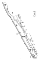
figure 1 shows, in an isometric exploded view parts of an embodiment of the open roof construction in accordance with the present invention; -
figure 2 illustrates the embodiment offigure 1 in an assembled position; -
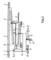
figure 3 is a schematical side elevational representation of an open roof construction in accordance with the present invention, and -
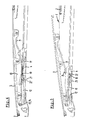
figures 4-7 illustrate in a side elevational view the cooperation of parts of an open roof construction in accordance with the present invention in four different positions. - The open roof construction for a vehicle in accordance with the present invention comprises a
roof opening 1 defined in astationary roof part 2 and amovable panel 3 for opening and closing said roof opening (for some of these elements reference is made tofigures 3 until 7). - Referring to
figure 1 , aslide 4 is illustrated which is movable along a stationary slide guide 5 (seefigure 3 ). - As illustrated, for example, in
figure 3 , the movement of theslide 4 may be obtained bydrive means 6, for example a drive cable known per se. Theslide 4 may be provided withguide shoes 7 cooperating with thestationary slide guide 5. - The
slide 4 comprises panel engagement means 8 for cooperation with apanel curve 9 of the movable panel. In the embodiment illustrated infigure 1 said panel engagement means 8 are defined by a T-shaped recess, whereas thepanel curve 9 is defined by a correspondingly shaped longitudinal T-shaped member being part of abracket 10 which, in a manner not illustrated in detail, is connected to themovable panel 3. - The
slide 4 further comprises aslide curve 11 which, in the embodiment illustrated here, has an inclined extension, as will be elucidated below. - The open roof construction further comprises a
locking lever 12 which by means of ahinge pin 13 can be connected to a corresponding hinge point 14 on the (bracket of the)panel 3. - In the embodiment illustrated in
figure 1 thelocking lever 12 is constructed as a member having a U-shaped cross section with two distancedwebs bracket 10 of the)panel 3. - The locking lever further is provided with a slide engagement means 18, in the illustrated embodiment a pin, which will cooperate with the
slide curve 11 of theslide 4. Further thelocking lever 12 comprises guide means 19 cooperating with a stationary lever guide 20 (illustrated infigure 3 ) and alocking member 21 cooperating with astationary locking guide 22. -
Figure 2 shows the parts represented infigure 1 in an assembled position, in which a connection between thelocking lever 12 and bracket 10 (and thus panel 3) is defined by the hinge pin 13 (and hinge point 14, not visible here), and wherein the T-shaped recess 8 receives the T-shaped member 9. Further, in this position the pin 18 (not visible here) is received in theslide curve 11 and the locking member 21 (neither visible here) is received in thestationary locking guide 22. -
Figure 3 shows schematically the relative positions and cooperation between the respective parts of the open roof construction in accordance with the present invention. It is noted, thatfigure 3 only shows a possible embodiment, and that other embodiments are possible. -
Figure 3 shows a situation, in which thepanel 3 closes the roof opening 1 and in which thelocking member 21 of thelocking lever 12 is positioned in a first part 22' of thestationary locking guide 22. This first stationary locking guide part 22' extends substantially vertically and connects to a second stationarylocking guide part 22" extending substantially horizontally (or, more correctly, in parallel to the direction of movement of the slide 4). - When, starting in the position illustrated in
figure 3 , theslide 4 is moved to the left, the slide engagement means 18 of thelocking lever 12 will slide in theslide curve 11 because thelocking lever 12 cannot move to the left (this is prevented by the position of thelocking member 21 in the vertically extending first stationary locking guide part 22'); as a consequence, the panel 3 (which is connected to thelocking lever 12 at the hinge point 14) neither will follow the movement of theslide 4. - During the movement of the
slide 4 to the left its panel engagement means 8 moves along thepanel curve 9 which extends inclined downwardly (to the left), such that thepanel 3 will rotate around hinge point 14 to an upwardly tilted position. - It is noted, that the
slide curve 11 may be provided with such an inclination that thelocking lever 12, during such a movement of theslide 4, will slightly rotate around the guide means 19 such that thehinge pin 13/hinge point 14 and thus thepanel 3 obtains a corresponding movement, which may be necessary to obtain or maintain an appropriate position at the leading edge of thepanel 3 where it engages thestationary roof part 2. In addition a longitudinal displacement of thepanel 3 can be generated by moving the vertically extending first stationary locking guide part 22' out of the vertical and/or moving thelocking guide part 22" out of the horizontal orientation. - Again referring to
figure 3 , when the slide 4 (as driven by drive cable 6) is moved to the right, firstly panel engagement means 8 moves along thepanel curve 9 and thus thepanel 3 will rotate around hinge point 14 to a downwardly tilted position. Meanwhile the slide engagement means 18 of thelocking lever 12 is moved to the left relative to and in theslide curve 11 of theslide 4, and eventually will reach an upwardly extending part 11' thereof. As a result, the slide engagement means 18 andlever 12 will move upwardly and thelocking member 21 will move upwardly out of the vertically extending stationary locking guide part 22'. Thelocking member 21 then will enter the horizontally extending stationarylocking guide part 22", such that thelocking lever 12 now may move along with theslide 4 to the right. As a consequence, thepanel 3 also will move to the right. - The above means, that, during the movement of the
slide 4 to the right, thepanel 3 firstly is moved to a downwardly tilted position and then is slid to the right underneath the adjacentstationary roof part 2. - For again closing the panel 3 a reverse movement of the
slide 4 to the left will lead to a reversed order of movements of the respective parts of the open roof construction. - In the illustrated embodiments the guide means 19, as seen in lengthwise direction of the
locking lever 12, is positioned between the hinge pin 13 (hinge point 14) and the slide engagement means 18. However, it is possible too that the hinge pin 13 (hinge point 14) is positioned between the guide means 19 and the slide engagement means 18, or that the hinge pin 13 (hinge point 14), as seen in lengthwise direction of thelocking lever 12, coincides with the guide means 19 of the locking lever. Such different embodiments will lead to different movements of the hinge point 14 (and, thus, the leading edge of the panel 3) in an upward or downward direction when thelocking lever 12 is rotated around the guide means 19 as a result of the slide engagement means 18 thereof moving in an inclined (part of the)slide curve 11 of theslide 4. Thus one can choose the most appropriate movement of the leading edge of thepanel 3, depending on the respective circumstances. - The position of the
locking member 21 also may be changed; in stead of being a separate member as illustrated here, such alocking member 21 for example also could coincide with thehinge pin 13 or with the slide engagement means 18. - Further it is noted, that, whereas in
figure 3 thestationary slide guide 5 andstationary lever guide 20 are illustrated as distinct members, such guides also could be combined into one single guide. - Finally, reference is made to
figures 4-7 in which an embodiment of the open roof construction in accordance with the present invention is illustrated in four different positions:figure 4 shows a closed position (basically in correspondence withfigure 3 );figure 5 shows a position in which thepanel 3 is rotated upwardly to a tilt position;figure 6 shows a position in which thepanel 3 is rotated downwardly to a tilt position andfigure 7 shows a position in which thepanel 3, starting from the position illustrated infigure 6 , is moved to the right. - In
figure 4 theslide 4 is in a central position andlocking member 21 is received in the vertically extending stationary locking guide part 22'. Infigure 5 slide 4 has been moved to the left thus liftingpanel 3 to a tilt position due to the cooperation between the panel engagement means 8 andpanel curve 9. Thelocking member 21 remains in the stationary locking guide part 22', thus maintaining thelocking lever 12 andpanel 3 in the same longitudinal position. The slide engagement means 18 has moved to the right relative to and in theslide curve 11. - Referring to
figure 6 , theslide 4 now has been moved to the right, starting from the position illustrated infigure 4 . As a result, thepanel 3 is rotated to a downwardly tilt position (again as a result of the cooperation between the panel engagement means 8 of theslide 4 and the panel curve 9). The slide engagement means (pin) 18 of thelocking lever 12 has moved to the left relative to an in theslide curve 11 and has nearly reached the upwardly extending part 11' thereof. Thelocking lever 12, due to the inclined extension of theslide curve 12, has been moved upwardly slightly with its end carrying the slide engagement means 18, such that thelocking member 21 of thelocking lever 12 is moved upwardly to a position at the transition between the vertically extending stationary locking guide part 22' and horizontally extending stationarylocking guide part 22". - In
figure 7 theslide 4 has moved still further to the right and the slide engagement means 18 has been moved to its uppermost position in the slide curve part 11'. As a result, thelocking member 21 has left the stationary locking guide part 22' and has entered the stationarylocking guide part 22". Now thelever 12, together with thepanel 3, moves along with theslide 4 to the right. - The invention is not limited to the embodiments described before, which may be varied widely within the scope of the invention as defined by the appending claims. It is noted that an additional control of the panel move-mentt can be obtained when the lever guide at least partially is tilted or inclined.
Claims (15)
- Open roof construction for a vehicle, comprising a roof opening (1) defined in a stationary roof part (2) and a movable panel (3) for opening and closing said roof opening, with a slide (4) which is movable along a stationary slide guide(5) and which is provided with panel engagement means (8) cooperating with a panel curve (9) of the movable panel, wherein a movement of the slide is capable of generating a tilting and/or sliding movement of the panel (3), characterized by a locking lever (12) which by means of a hinge point (14) is connected to the panel and which is provided firstly slide engagement means (18) cooperating with a slide curve (11) of the slide, secondly with guide means (19) cooperating with a stationary lever guide (20) and thirty with a locking member (21) cooperating with a stationary locking guide (22), such that in a first position of the slide (4) the locking member (21) is housed in a first stationary locking guide part (22') preventing a translational movement of the locking lever (12) and panel (3) connected therewith and in a second position of the slide the locking member (21) is housed in a second stationary locking guide part (22") allowing a translational movement of the locking lever (12), and thus of the panel (3) connected therewith at the hinge point (14).
- Open roof construction according to claim 1, wherein the slide curve (11) has an inclined extension, such that when moving the slide (4) relative to the locking lever (12) the cooperation between the slide curve (11) and slide engagement means (18) will move the locking member (21) in or out of, respectively, the first stationary locking guide part (22').
- Open roof construction according to claim 1 or 2, wherein the first stationary locking guide part (22') extends substantially vertically, whereas the second stationary locking guide part (22") extends substantially horizontally.
- Open roof construction according to claim 1 or 2, wherein the first stationary locking guide part (22') extends inclined relative to the vertical and/or the second station-(22") ary locking guide part (22") extends inclined relative to the horizontal and/or the lever guide (20) extends inclined relative to the horizontal.
- Open roof construction according to any of the previous claims, wherein, as seen in lengthwise direction of the locking lever (12), the guide means (19) is positioned between the hinge point (14) and the slide engagement means (18) of the locking lever (12).
- Open roof construction according to any of the claims 1-4, wherein, as seen in lengthwise direction of the locking lever (12), the hinge point (14) is positioned between the guide means (19) and the slide engagement means (18) of the locking lever (12).
- Open roof construction according to any of the claims 1-4, wherein, as seen in lengthwise direction of the locking lever (12), the hinge point (14) coincides with the guide means (19) of the locking lever (12).
- Open roof construction according to any of the previous claims, wherein the locking member (21) coincides with the slide engagement means (18).
- Open roof construction according to any of the claims 1-7, wherein the locking member (21) coincides with the hinge point (14).
- Open roof construction according to any of the previous claims, wherein the stationary slide guid (5) and the stationary lever guide (20) coincide.
- Open roof construction according to any of the previous claims, wherein the locking lever (12) is constructed as a plate-shaped member.
- Open roof construction according to any of the claims 1-10, wherein the locking lever (12) is constructed as a member having a U-shaped cross section with two distanced webs (15, 16) defining there between a gap (17) for at least partially receiving a part of the panel (3) which is provided with the panel curve (9).
- Open roof construction according to any of the previous claims, wherein the panel curve (9) is defined by a longitudinal T-shaped member and wherein the panel engagement means (8) of the slide (4) correspondingly define a T-shaped recess for receiving the T-shaped member.
- Open roof construction according to any of the previous claims, wherein the shape of the slide curve (11) and panel curve (9) is such that during a movement of the slide (4) in a first direction the locking member (21) remains in the first stationary locking guide part (22') and the panel (3) is tilted upwardly to an open position, whereas during a movement of the slide (4) in the opposite direction the locking member (21) is moved out of the first stationary locking guide part (22'), and into the second stationary locking guide part (22"), and the panel (3) is firstly tilted downwardly to an open position and secondly slid along with the slide (4) in said opposite direction.
- Open roof construction according to claim 14, wherein said first direction is the forward direction of the vehicle and said opposite direction is the rearward direction of the vehicle.
Priority Applications (7)
| Application Number | Priority Date | Filing Date | Title |
|---|---|---|---|
| DE602007013548T DE602007013548D1 (en) | 2007-07-16 | 2007-07-16 | Open roof construction for a vehicle |
| EP07112527A EP2017108B1 (en) | 2007-07-16 | 2007-07-16 | Open roof construction for a vehicle |
| JP2008182859A JP5311906B2 (en) | 2007-07-16 | 2008-07-14 | Open roof structure for vehicles |
| US12/172,500 US7753438B2 (en) | 2007-07-16 | 2008-07-14 | Open roof construction for a vehicle |
| CN2008101611454A CN101367327B (en) | 2007-07-16 | 2008-07-15 | Open roof construction for a vehicle |
| CA002637866A CA2637866A1 (en) | 2007-07-16 | 2008-07-15 | Open roof construction for a vehicle |
| MX2008009216A MX2008009216A (en) | 2007-07-16 | 2008-07-16 | Open roof construction for a vehicle. |
Applications Claiming Priority (1)
| Application Number | Priority Date | Filing Date | Title |
|---|---|---|---|
| EP07112527A EP2017108B1 (en) | 2007-07-16 | 2007-07-16 | Open roof construction for a vehicle |
Publications (2)
| Publication Number | Publication Date |
|---|---|
| EP2017108A1 EP2017108A1 (en) | 2009-01-21 |
| EP2017108B1 true EP2017108B1 (en) | 2011-03-30 |
Family
ID=38659647
Family Applications (1)
| Application Number | Title | Priority Date | Filing Date |
|---|---|---|---|
| EP07112527A Active EP2017108B1 (en) | 2007-07-16 | 2007-07-16 | Open roof construction for a vehicle |
Country Status (7)
| Country | Link |
|---|---|
| US (1) | US7753438B2 (en) |
| EP (1) | EP2017108B1 (en) |
| JP (1) | JP5311906B2 (en) |
| CN (1) | CN101367327B (en) |
| CA (1) | CA2637866A1 (en) |
| DE (1) | DE602007013548D1 (en) |
| MX (1) | MX2008009216A (en) |
Families Citing this family (23)
| Publication number | Priority date | Publication date | Assignee | Title |
|---|---|---|---|---|
| EP2234831B1 (en) | 2009-02-09 | 2012-06-20 | Webasto AG | Mechanism for an adjustable chassis component of a vehicle |
| DE102009011472B4 (en) | 2009-03-03 | 2011-06-09 | Webasto Ag | Vehicle roof with drive carriage for cover element |
| EP2305500B1 (en) * | 2009-10-05 | 2013-09-25 | Inalfa Roof Systems Group B.V. | Open roof construction for a vehicle |
| US8297692B2 (en) * | 2009-11-20 | 2012-10-30 | AISIN Technical Center of America, Inc. | Tiltable sun roof for vehicles |
| JP5638367B2 (en) * | 2010-12-06 | 2014-12-10 | ベバスト ジャパン株式会社 | Sunroof device |
| KR101245802B1 (en) * | 2010-12-17 | 2013-03-21 | 주식회사 엠에스 오토텍 | Sunroof panel opening/closing apparatus |
| DE102011119991B3 (en) | 2011-12-02 | 2012-05-24 | Webasto Ag | Side panel of a vehicle roof to be opened |
| EP2644422B1 (en) * | 2012-03-26 | 2014-10-15 | Inalfa Roof Systems Group B.V. | Open roof construction for a vehicle |
| CN102848889A (en) * | 2012-10-10 | 2013-01-02 | 上海毓恬冠佳汽车零部件有限公司 | Skylight sliding system |
| JP6079283B2 (en) * | 2013-02-08 | 2017-02-15 | アイシン精機株式会社 | Sunroof device for vehicle |
| JP6264793B2 (en) * | 2013-09-06 | 2018-01-24 | アイシン精機株式会社 | Sunroof device for vehicle |
| JP6268829B2 (en) | 2013-09-06 | 2018-01-31 | アイシン精機株式会社 | Sunroof device for vehicle |
| JP6286956B2 (en) * | 2013-09-06 | 2018-03-07 | アイシン精機株式会社 | Sunroof device for vehicle |
| DE102014110234A1 (en) * | 2014-05-14 | 2015-11-19 | Webasto SE | Arrangement with a cover for a vehicle roof |
| JP6330558B2 (en) * | 2014-07-31 | 2018-05-30 | アイシン精機株式会社 | Sunroof device |
| EP3034343B1 (en) * | 2014-12-17 | 2020-05-13 | Inalfa Roof Systems Group B.V. | Roof system for a vehicle |
| CN104589974B (en) * | 2014-12-19 | 2017-01-18 | 成都飞机设计研究所 | Time sequence logic control mechanism |
| DE102015203056A1 (en) * | 2015-02-20 | 2016-08-25 | Magna Car Top Systems Gmbh | Opening / closing mechanism for a fabric roof or folding roof of a vehicle |
| CN105480063B (en) * | 2015-03-31 | 2017-09-26 | 苏州美驰汽车系统有限公司 | Panoramic roofs machinery group |
| DE102015105380A1 (en) * | 2015-04-09 | 2016-10-13 | Webasto SE | Arrangement with a cover for a vehicle roof and vehicle roof for a motor vehicle |
| EP3476632B1 (en) * | 2017-10-31 | 2020-05-27 | Inalfa Roof Systems Group B.V. | Open roof construction for a vehicle |
| DE202018102477U1 (en) * | 2018-05-03 | 2019-08-12 | Inalfa Roof Systems Group B.V. | Locking mechanism and thus provided open roof construction |
| US11390150B2 (en) * | 2019-09-19 | 2022-07-19 | Inalfa Roof Systems Group B.V. | Support mechanism for an open-roof assembly in a vehicle roof |
Family Cites Families (7)
| Publication number | Priority date | Publication date | Assignee | Title |
|---|---|---|---|---|
| JPS6353114A (en) * | 1986-08-22 | 1988-03-07 | Aisin Seiki Co Ltd | T-bar roof |
| JPH08175185A (en) * | 1994-12-28 | 1996-07-09 | Aisin Seiki Co Ltd | Movable panel |
| DE10158174B4 (en) * | 2001-11-28 | 2004-06-17 | Webasto Vehicle Systems International Gmbh | Sunroof for vehicles |
| JP2003211967A (en) * | 2002-01-21 | 2003-07-30 | Honda Motor Co Ltd | Glass panel of sun roof device |
| WO2004103752A1 (en) * | 2003-05-20 | 2004-12-02 | Grupo Antolin-Ingenieria, S.A. | Sunroof support frame for motor vehicle |
| DE10333781B4 (en) * | 2003-07-24 | 2007-04-19 | Webasto Ag | Openable vehicle roof |
| DE102004061376A1 (en) * | 2004-12-21 | 2006-06-22 | Bayerische Motoren Werke Ag | Cover for vehicle roof, has adjusting unit in which transverse axis forming front swivel axis for cover is formed, and adjusting mechanism adjusting adjusting unit in elevation and/or vehicle length direction |
-
2007
- 2007-07-16 EP EP07112527A patent/EP2017108B1/en active Active
- 2007-07-16 DE DE602007013548T patent/DE602007013548D1/en active Active
-
2008
- 2008-07-14 JP JP2008182859A patent/JP5311906B2/en active Active
- 2008-07-14 US US12/172,500 patent/US7753438B2/en active Active
- 2008-07-15 CA CA002637866A patent/CA2637866A1/en not_active Abandoned
- 2008-07-15 CN CN2008101611454A patent/CN101367327B/en active Active
- 2008-07-16 MX MX2008009216A patent/MX2008009216A/en active IP Right Grant
Also Published As
| Publication number | Publication date |
|---|---|
| CA2637866A1 (en) | 2009-01-16 |
| EP2017108A1 (en) | 2009-01-21 |
| MX2008009216A (en) | 2009-03-05 |
| JP5311906B2 (en) | 2013-10-09 |
| CN101367327A (en) | 2009-02-18 |
| DE602007013548D1 (en) | 2011-05-12 |
| CN101367327B (en) | 2012-08-15 |
| JP2009018799A (en) | 2009-01-29 |
| US20090021056A1 (en) | 2009-01-22 |
| US7753438B2 (en) | 2010-07-13 |
Similar Documents
| Publication | Publication Date | Title |
|---|---|---|
| EP2017108B1 (en) | Open roof construction for a vehicle | |
| US5971473A (en) | Adjustment apparatus for a sunroof | |
| EP2559576B1 (en) | Sunroof apparatus | |
| EP2254764B1 (en) | Open roof construction for a vehicle | |
| EP2650157B1 (en) | Sunroof apparatus | |
| EP1424234B1 (en) | An open roof construction for a vehicle | |
| EP2263896B1 (en) | Open roof construction for a vehicle | |
| EP3476632B1 (en) | Open roof construction for a vehicle | |
| EP1494883B1 (en) | Roof assembly for a vehicle | |
| EP1331119B1 (en) | Vehicle with sliding and venting sunroof | |
| EP3647094B1 (en) | Roof system for a vehicle | |
| US7367614B2 (en) | Multi-panel sunshade device | |
| US11331988B2 (en) | Roof system for a vehicle | |
| JP4411985B2 (en) | Sunroof device | |
| WO2015188863A1 (en) | A drive mechanism for a sunroof of a vehicle and a sunroof apparatus including the same | |
| EP4289647A1 (en) | Roof system for a vehicle | |
| US11607937B2 (en) | Roof system for a vehicle | |
| JP2002166727A (en) | Sunshine roof device | |
| EP1533160B1 (en) | Actuating device for an open roof construction for a vehicle | |
| JPH01257622A (en) | Separate sun roof for automobile |
Legal Events
| Date | Code | Title | Description |
|---|---|---|---|
| PUAI | Public reference made under article 153(3) epc to a published international application that has entered the european phase |
Free format text: ORIGINAL CODE: 0009012 |
|
| AK | Designated contracting states |
Kind code of ref document: A1 Designated state(s): AT BE BG CH CY CZ DE DK EE ES FI FR GB GR HU IE IS IT LI LT LU LV MC MT NL PL PT RO SE SI SK TR |
|
| AX | Request for extension of the european patent |
Extension state: AL BA HR MK RS |
|
| 17P | Request for examination filed |
Effective date: 20090709 |
|
| 17Q | First examination report despatched |
Effective date: 20090820 |
|
| AKX | Designation fees paid |
Designated state(s): DE FR GB |
|
| GRAP | Despatch of communication of intention to grant a patent |
Free format text: ORIGINAL CODE: EPIDOSNIGR1 |
|
| GRAS | Grant fee paid |
Free format text: ORIGINAL CODE: EPIDOSNIGR3 |
|
| GRAA | (expected) grant |
Free format text: ORIGINAL CODE: 0009210 |
|
| AK | Designated contracting states |
Kind code of ref document: B1 Designated state(s): DE FR GB |
|
| REG | Reference to a national code |
Ref country code: GB Ref legal event code: FG4D |
|
| REF | Corresponds to: |
Ref document number: 602007013548 Country of ref document: DE Date of ref document: 20110512 Kind code of ref document: P |
|
| REG | Reference to a national code |
Ref country code: DE Ref legal event code: R096 Ref document number: 602007013548 Country of ref document: DE Effective date: 20110512 |
|
| PLBE | No opposition filed within time limit |
Free format text: ORIGINAL CODE: 0009261 |
|
| STAA | Information on the status of an ep patent application or granted ep patent |
Free format text: STATUS: NO OPPOSITION FILED WITHIN TIME LIMIT |
|
| 26N | No opposition filed |
Effective date: 20120102 |
|
| GBPC | Gb: european patent ceased through non-payment of renewal fee |
Effective date: 20110716 |
|
| REG | Reference to a national code |
Ref country code: DE Ref legal event code: R097 Ref document number: 602007013548 Country of ref document: DE Effective date: 20120102 |
|
| PG25 | Lapsed in a contracting state [announced via postgrant information from national office to epo] |
Ref country code: GB Free format text: LAPSE BECAUSE OF NON-PAYMENT OF DUE FEES Effective date: 20110716 |
|
| REG | Reference to a national code |
Ref country code: FR Ref legal event code: PLFP Year of fee payment: 10 |
|
| REG | Reference to a national code |
Ref country code: FR Ref legal event code: PLFP Year of fee payment: 11 |
|
| REG | Reference to a national code |
Ref country code: FR Ref legal event code: PLFP Year of fee payment: 12 |
|
| PGFP | Annual fee paid to national office [announced via postgrant information from national office to epo] |
Ref country code: DE Payment date: 20220727 Year of fee payment: 16 |
|
| PGFP | Annual fee paid to national office [announced via postgrant information from national office to epo] |
Ref country code: FR Payment date: 20230725 Year of fee payment: 17 |
|
| REG | Reference to a national code |
Ref country code: DE Ref legal event code: R119 Ref document number: 602007013548 Country of ref document: DE |