EP2644392A2 - System for printing of an object - Google Patents
System for printing of an object Download PDFInfo
- Publication number
- EP2644392A2 EP2644392A2 EP13156896.6A EP13156896A EP2644392A2 EP 2644392 A2 EP2644392 A2 EP 2644392A2 EP 13156896 A EP13156896 A EP 13156896A EP 2644392 A2 EP2644392 A2 EP 2644392A2
- Authority
- EP
- European Patent Office
- Prior art keywords
- movement
- printing
- detector
- robot
- printhead
- Prior art date
- Legal status (The legal status is an assumption and is not a legal conclusion. Google has not performed a legal analysis and makes no representation as to the accuracy of the status listed.)
- Granted
Links
Images


Classifications
-
- B—PERFORMING OPERATIONS; TRANSPORTING
- B41—PRINTING; LINING MACHINES; TYPEWRITERS; STAMPS
- B41J—TYPEWRITERS; SELECTIVE PRINTING MECHANISMS, i.e. MECHANISMS PRINTING OTHERWISE THAN FROM A FORME; CORRECTION OF TYPOGRAPHICAL ERRORS
- B41J25/00—Actions or mechanisms not otherwise provided for
- B41J25/001—Mechanisms for bodily moving print heads or carriages parallel to the paper surface
-
- B—PERFORMING OPERATIONS; TRANSPORTING
- B41—PRINTING; LINING MACHINES; TYPEWRITERS; STAMPS
- B41J—TYPEWRITERS; SELECTIVE PRINTING MECHANISMS, i.e. MECHANISMS PRINTING OTHERWISE THAN FROM A FORME; CORRECTION OF TYPOGRAPHICAL ERRORS
- B41J2/00—Typewriters or selective printing mechanisms characterised by the printing or marking process for which they are designed
- B41J2/005—Typewriters or selective printing mechanisms characterised by the printing or marking process for which they are designed characterised by bringing liquid or particles selectively into contact with a printing material
- B41J2/01—Ink jet
- B41J2/135—Nozzles
-
- B—PERFORMING OPERATIONS; TRANSPORTING
- B05—SPRAYING OR ATOMISING IN GENERAL; APPLYING FLUENT MATERIALS TO SURFACES, IN GENERAL
- B05B—SPRAYING APPARATUS; ATOMISING APPARATUS; NOZZLES
- B05B1/00—Nozzles, spray heads or other outlets, with or without auxiliary devices such as valves, heating means
- B05B1/14—Nozzles, spray heads or other outlets, with or without auxiliary devices such as valves, heating means with multiple outlet openings; with strainers in or outside the outlet opening
-
- B—PERFORMING OPERATIONS; TRANSPORTING
- B05—SPRAYING OR ATOMISING IN GENERAL; APPLYING FLUENT MATERIALS TO SURFACES, IN GENERAL
- B05B—SPRAYING APPARATUS; ATOMISING APPARATUS; NOZZLES
- B05B13/00—Machines or plants for applying liquids or other fluent materials to surfaces of objects or other work by spraying, not covered by groups B05B1/00 - B05B11/00
- B05B13/02—Means for supporting work; Arrangement or mounting of spray heads; Adaptation or arrangement of means for feeding work
- B05B13/04—Means for supporting work; Arrangement or mounting of spray heads; Adaptation or arrangement of means for feeding work the spray heads being moved during spraying operation
- B05B13/0447—Installation or apparatus for applying liquid or other fluent material to conveyed separate articles
- B05B13/0452—Installation or apparatus for applying liquid or other fluent material to conveyed separate articles the conveyed articles being vehicle bodies
-
- B—PERFORMING OPERATIONS; TRANSPORTING
- B41—PRINTING; LINING MACHINES; TYPEWRITERS; STAMPS
- B41J—TYPEWRITERS; SELECTIVE PRINTING MECHANISMS, i.e. MECHANISMS PRINTING OTHERWISE THAN FROM A FORME; CORRECTION OF TYPOGRAPHICAL ERRORS
- B41J3/00—Typewriters or selective printing or marking mechanisms characterised by the purpose for which they are constructed
- B41J3/407—Typewriters or selective printing or marking mechanisms characterised by the purpose for which they are constructed for marking on special material
- B41J3/4073—Printing on three-dimensional objects not being in sheet or web form, e.g. spherical or cubic objects
Landscapes
- Engineering & Computer Science (AREA)
- Manufacturing & Machinery (AREA)
- Ink Jet (AREA)
- Coating Apparatus (AREA)
- Manipulator (AREA)
- Spray Control Apparatus (AREA)
Abstract
Description
Die vorliegende Erfindung betrifft ein System zum Bedrucken eines Objekts gemäß Anspruch 1, welches wenigstens einen nicht ebenen Bereich der Oberfläche des Objekts mit einem Bild bedruckt.The present invention relates to a system for printing an object according to claim 1, which prints at least one non-planar area of the surface of the object with an image.
Im Stand der Technik ist es bereits bekannt, nicht ebene Bereiche der Oberfläche eines Objekts, z. B. gekrümmte Abschnitte von Karosserien von Fahrzeugen, mit einem Tintenstrahl-Druckkopf zu bedrucken und dabei beliebige, mehrfarbige Bilder auf der Oberfläche zu erzeugen. Zu diesem Zweck wird der Druckkopf an einem Roboter, z. B. einem Gelenkarmroboter, entlang der Oberfläche des Objekts in einem definierten Abstand zur Oberfläche geführt, so dass die vom Druckkopf ausgestoßenen Tintentröpfchen an die gewünschten Stellen auf der Oberfläche gelangen und dort das gewünschte Bild erzeugen. Da die Oberfläche des Objekts in der Regel weitaus größer als die Ausdehnung des Druckkopfes ist, ist es notwendig, den Druckkopf mehrfach auf sogenannten Druckbahnen entlang der Oberfläche zu führen und das gewünschte Druckbild aus den nebeneinander liegenden Druckbahnen aufzubauen. Dabei ist es wiederum erforderlich, dass die Druckbahnen derart aneinander anschließen, dass keine optisch wahrnehmbaren Störungen an den Kanten der Druckbahnen erzeugt werden. Wird z. B. eine zweite Druckbahn in zu großem Abstand zur ersten Druckbahn erzeugt, so kann es sein, dass zwischen den beiden Druckbahnen ein wahrnehmbarer Streifen entsteht, der das gewünschte Druckbild stört. Gleichfalls kann es möglich sein, dass die beiden Druckbahnen zu weit überlappen und dadurch ebenfalls ein wahrnehmbarer Streifen zwischen den beiden Druckbahnen entsteht, der das gewünschte Druckbild stören kann. Solche Störungen im Druckbild können z.B. dann entstehen, wenn die Mechanik der Druckkopf-Führung keine ausreichende Präzision aufweist. Sie können aber z.B. auch entstehen, wenn der Druckkopf während seiner Bewegung Fliehkräften ausgesetzt ist, so dass die ausgestoßenen Tropfen nicht an den gewünschten Stellen auf der Oberfläche platziert werden.In the prior art, it is already known, non-planar areas of the surface of an object, for. B. curved sections of bodies of vehicles to print with an inkjet printhead and thereby produce any multicolored images on the surface. For this purpose, the printhead is attached to a robot, e.g. As an articulated arm robot, guided along the surface of the object at a defined distance from the surface, so that the ejected from the print head ink droplets reach the desired locations on the surface and generate the desired image there. Since the surface of the object is usually much larger than the extent of the print head, it is necessary to repeatedly guide the print head on so-called print paths along the surface and build the desired print image from the juxtaposed print webs. In this case, it is again necessary for the printing webs to adjoin one another in such a way that no visually perceptible disturbances are produced at the edges of the printing webs. If z. For example, if a second printing web is generated at too great a distance from the first printing web, then it may be that a perceptible strip is formed between the two printing webs, which disturbs the desired printed image. Likewise, it may be possible that the two printing webs overlap too far and thus also creates a noticeable strip between the two printing webs, which can disturb the desired printed image. Such disturbances in the printed image can arise, for example, when the mechanics of the print head guide does not have sufficient precision. However, they may also arise, for example, when the printhead is subjected to centrifugal forces during its movement, so that the ejected drops are not placed at the desired locations on the surface.
Es ist beispielsweise aus der
In der vom gleichen Patentanmelder stammenden
Die
Die
Aus der
Vor diesem Hintergrund ist es eine Aufgabe der vorliegenden Erfindung, ein System zum Bedrucken eines Objektes, welches wenigstens einen nicht ebenen Bereich der Oberfläche eines Objektes mit einem Bild bedruckt, zu schaffen, welches Streifenbildung beim Bedrucken der Oberfläche in mehreren Druckbahnen verhindert oder wenigstens soweit reduziert, dass die verbleibenden Streifen nicht als störend wahrgenommen werden.Against this background, it is an object of the present invention to provide a system for printing an object which imprints at least one non-planar area of the surface of an object with an image, which prevents or at least reduces striping when printing the surface in multiple printing webs in that the remaining strips are not perceived as disturbing.
Diese Aufgabe wird mit den Merkmalen von Anspruch 1 gelöst. Vorteilhafte Weiterbildungen der Erfindung ergeben sich aus den zugehörigen Unteransprüchen sowie aus der Beschreibung und den Zeichnungen.This object is achieved with the features of claim 1. Advantageous developments of the invention will become apparent from the accompanying dependent claims and from the description and the drawings.
Ein erfindungsgemäßes System zum Bedrucken eines Objektes, welches wenigstens einen nicht ebenen Bereich der Oberfläche des Objekts mit einem Bild bedruckt, weist folgende Merkmale auf: ein Tintenstrahl-Druckkopf mit Düsen; ein Roboter, welcher eine Primärbewegung erzeugt, wobei die Primärbewegung wenigstens zwei seitlich zueinander liegende Druckbahnen des Tintenstrahl-Druckkopfs umfasst; und eine Vorrichtung, welche eine Sekundärbewegung erzeugt, wobei die Sekundärbewegung im Wesentlichen senkrecht zur Primärbewegung erfolgt und wodurch die Druckbahnen seitlich aneinander anschließen.An inventive system for printing an object which imprints at least one non-planar area of the surface of the object with an image has the following features: an ink-jet printhead with nozzles; a robot which generates a primary movement, the primary movement comprising at least two laterally juxtaposed printing paths of the inkjet printhead; and a device which generates a secondary movement, wherein the secondary movement is substantially perpendicular to the primary movement and whereby the pressure paths laterally adjoin one another.
Das Vorsehen der Vorrichtung zur Erzeugung von Sekundärbewegungen in dem erfindungsgemäßen System führt in vorteilhafterweise dazu, dass Positionsabweichungen des Tintenstrahl-Druckkopfs, d. h. Abweichungen der Ist-Position von der Soll-Position für das Drucken eines fehlerfreien Bildes, während der Primärbewegung ausgeglichen werden können, wodurch sichtbare und daher störende Streifen zwischen den Druckbahnen verhindert oder ausreichend reduziert werden können. Dass die Druckbahnen seitlich aneinander anschließen, meint dabei, dass die Kanten der einzelnen Druckbahnen derart exakt nebeneinander liegen, dass weder zu große Abstände zwischen den Kanten noch ein zu großer Überlapp erzeugt wird und dass dadurch störende, insbesondere zu helle oder zu dunkle Streifen im Bereich der Kanten der Druckbahnen verhindert oder ausreichend reduziert werden. Die Primärbewegung, welche der Roboter erzeugt ist dabei bevorzugt eine Bewegung des Tintenstrahl-Druckkopfes, welcher beispielsweise mehrere, seitlich zueinander liegende Druckbahnen in gleicher Richtung oder auch in entgegengesetzter Richtung durchläuft. Beispielsweise kann eine erste Druckbahn bei einer Hinbewegung des Druckkopfes über der Oberfläche des Objektes erzeugt werden und eine zweite an diese anschließende Druckbahn bei einer Rückbewegung des Druckkopfes benachbart zur ersten Druckbahn. Es kann jedoch auch vorgesehen sein, den Druckkopf zunächst inaktiv zurückzuführen und parallel zur ersten Druckbahn wieder vorwärts zu bewegen. Der Roboter kann ein Gelenkarm-Roboter oder eine Portal-Roboter sein.The provision of the device for generating secondary movements in the system according to the invention advantageously leads to positional deviations of the inkjet printhead, i. H. Deviations of the actual position from the desired position for printing a defect-free image, during the primary movement can be compensated, whereby visible and therefore disturbing stripes between the printing webs can be prevented or reduced sufficiently. The fact that the pressure paths laterally adjoin one another, means that the edges of the individual printing webs are so exactly adjacent to each other that neither too large distances between the edges still too much overlap is generated and thereby annoying, especially too light or too dark stripes in the area the edges of the printing lines are prevented or reduced sufficiently. The primary movement, which is generated by the robot is preferably a movement of the inkjet printhead, which passes through, for example, a plurality of laterally juxtaposed printing webs in the same direction or in the opposite direction. For example, a first printing web can be generated during a forward movement of the print head over the surface of the object, and a second printing web adjacent thereto during a return movement of the print head adjacent to the first printing web. However, it can also be provided to initially return the print head inactive and to move it forward again parallel to the first print web. The robot may be an articulated arm robot or a portal robot.
Eine vorteilhafte Weiterbildung des erfindungsgemäßen Systems sieht vor, dass die Vorrichtung einen Piezo-Aktor bzw. ein elektro-mechanisches Bauelement umfasst und die Sekundärbewegung eine Bewegung des Tintenstrahl-Druckkopfes ist. Der Piezo-Aktor wirkt dabei auf den Tintenstrahl-Druckkopf als Ganzes ein und bewirkt, dass dieser senkrecht zur Primärbewegung die Sekundärbewegung als Ausgleichsbewegung ausführt.An advantageous development of the system according to the invention provides that the device comprises a piezoactuator or an electro-mechanical component and the secondary movement is a movement of the inkjet printhead. The piezo actuator acts on the inkjet printhead as a whole and causes it to perform perpendicular to the primary movement, the secondary movement as a compensating movement.
Gemäß einer weiteren vorteilhaften Weiterbildung des erfindungsgemäßen Systems ist es vorgesehen, dass die Vorrichtung einen Piezo-Aktor umfasst und die Sekundärbewegung eine Bewegung wenigstens einer Düse des Tintenstrahl-Druckkopfes ist. Gemäß dieser Weiterbildung wird somit nicht der Druckkopf als Ganzes, sondern lediglich wenigstens eine Düse senkrecht zur Primärbewegung bewegt. Dabei kann vorgesehen sein, dass die wenigstens eine Düse, eine Düsengruppe oder auch alle Düsen beweglich am Tintenstrahl-Druckkopf aufgenommen sind, so dass die Sekundärbewegung mittels des Piezo-Aktors als eine Relativbewegung bezüglich des Tintenstrahl-Druckkopfes erfolgt.According to a further advantageous embodiment of the system according to the invention, it is provided that the device comprises a piezoelectric actuator and the secondary movement is a movement of at least one nozzle of the inkjet printhead. According to this embodiment, therefore, not the printhead as a whole, but only at least one nozzle is moved perpendicular to the primary movement. It can be provided that the at least one nozzle, a nozzle group or even all nozzles are movably received on the inkjet printhead, so that the secondary movement by means of the piezo actuator takes place as a relative movement with respect to the inkjet printhead.
Es gemäß einer weiteren vorteilhaften Weiterbildung kann auch vorgesehen sein, dass die Sekundärbewegung weder den Druckkopf als Ganzes noch einzelne Düsen des Druckkopfes erfasst, sondern dass gemäß einer bevorzugten Weiterbildung des erfindungsgemäßen Systems die Vorrichtung einen Piezo-Aktor umfasst und die Sekundärbewegung eine Bewegung wenigstens der Tropfen einer Düse des Tintenstrahl-Druckkopfes ist. Dabei handelt es sich bei dem Piezo-Aktor nicht um einen Piezo-Aktor, der den Tropfen erzeugt, sondern um einen davon verschiedenen und separaten Piezo-Aktor.According to a further advantageous development, it can also be provided that the secondary movement does not detect the printhead as a whole nor individual nozzles of the printhead, but that according to a preferred embodiment of the system according to the invention the device comprises a piezoactuator and the secondary movement comprises a movement of at least the droplets a nozzle of the inkjet printhead is. The piezo actuator is not a piezoactuator that generates the droplet, but a separate and separate piezoactuator.
Eine weitere vorteilhafte Weiterbildung des erfindungsgemäßen Systems kann sich dadurch auszeichnen, dass die Vorrichtung einen Detektor umfasst, der die Ist-Positionen von Druckpunkten einer ersten Druckbahn erfasst; dass die Vorrichtung einen Rechner umfasst, der die Abweichung der Ist-Positionen der Druckpunkte von deren Soll-Positionen berechnet; und dass die Vorrichtung als Sekundärbewegung eine die Abweichung im Wesentlichen kompensierende Ausgleichsbewegung auf der zweiten Druckbahn erzeugt. Mit anderen Worten: die (mögliche störende Streifen) ausgleichende Sekundärbewegung findet auf Basis eines Soll-Ist-Wert-Vergleiches von bereits gedruckten Druckpunkten statt.A further advantageous development of the system according to the invention can be characterized in that the device comprises a detector which detects the actual positions of pressure points of a first pressure path; in that the apparatus comprises a computer which calculates the deviation of the actual positions of the pressure points from their desired positions; and that the device generates as a secondary movement a compensating movement substantially compensating for the deviation on the second printing web. In other words, the (possibly disturbing stripes) compensating secondary movement takes place on the basis of a desired-actual-value comparison of already printed pressure points.
Gemäß einer weiteren vorteilhaften Weiterbildung kann vorgesehen sein, dass die Vorrichtung wenigstens einen Detektor umfasst, dass der Roboter ein Gelenkarm-Roboter ist, und dass der Detektor einen Drehgeber umfasst, welcher die Winkelposition eines Gelenkes des Gelenkarm-Roboters erfasst. Sofern der Gelenkarm-Roboter mehrere Gelenke aufweist, wird bevorzugt an jedem Gelenk ein Detektor vorgesehen, so dass die Position des Roboters im Raum und insbesondere des am Roboter aufgenommenen Druckkopfes im Raum als Ist-Position exakt bestimmt werden kann. Sofern diese Ist-Position von einer vorgegebenen Soll-Position abweicht, kann eine Nachführung des Roboters erfolgen. Die Nachführung dient dabei als (mögliche störende Streifen) ausgleichende Sekundärbewegung. Alternativ können auch Beschleunigungssensoren, Neigungssensoren, Gyrometer Anwendung finden, um die Koordinaten des Druckkopfes im Raum und ggf. auch in zeitliche Abfolge zu bestimmen.According to a further advantageous development it can be provided that the device comprises at least one detector, that the robot is an articulated arm robot, and that the detector comprises a rotary encoder which detects the angular position of a joint of the articulated arm robot. If the articulated arm robot has a plurality of joints, a detector is preferably provided at each joint, so that the position of the robot in space and in particular of the print head recorded on the robot can be determined exactly in space as the actual position. If this actual position deviates from a predetermined desired position, tracking of the robot can take place. The tracking serves as (possible disturbing stripes) compensating secondary movement. Alternatively, acceleration sensors, inclination sensors, gyrometers can be used to determine the coordinates of the print head in space and possibly also in chronological order.
Es kann ferner gemäß einer weiteren vorteilhaften Weiterbildung des erfindungsgemäßen Systems vorgesehen sein, dass der Detektor einen optischen Sensor oder einen Ultraschall-Sensor umfasst, welcher auf die Oberfläche des Objektes gerichtet ist. Der Sensor kann beispielsweise auf der Oberfläche bereits zuvor gedruckte Druckpunkte des Bildes erfassen und daraus eine Kante der zuvor gedruckten Druckbahn bestimmen. Von Vorteil ist es dabei, wenn zumindest für die Druckfarbe von randnahen Düsen des Druckkopfes solche Druckfarben zum Einsatz kommen, die leicht mit dem Detektor aufgenommen werden können. Besonders von Vorteil ist dabei der Einsatz von speziellen Additiven in der Druckfarbe, welche beispielsweise eine Fluoreszenzeigenschaft aufweisen und deren Fluoreszenzlicht durch den Detektor mit hoher Präzision erfasst werden kann. Es kann daher gemäß einer weiteren vorteilhaften Weiterbildung des erfindungsgemäßen Systems vorgesehen sein, dass der optische Sensor auf bereits gedruckte Druckpunkte auf der Oberfläche gerichtet ist und deren Fluoreszenzstrahlung erfasst. Auf diese Weise wird es möglich, die Kante einer zuvor gedruckten Bahn präzise zu erfassen und die Kante einer noch zu druckenden Bahn präzise an die erfasste Kante auszurichten und dadurch störende Streifenbildung zu unterbinden oder zu verringern.It can also be provided according to a further advantageous development of the system according to the invention, that the detector comprises an optical sensor or an ultrasonic sensor, which is directed to the surface of the object. By way of example, the sensor can detect previously printed print dots of the image on the surface and determine therefrom an edge of the previously printed print web. It is advantageous if at least for the ink of near-edge nozzles of the print head such printing inks are used, which can be easily taken with the detector. Particularly advantageous is the use of special additives in the printing ink, which for example have a fluorescence property and whose fluorescent light can be detected by the detector with high precision. It may therefore be provided according to a further advantageous embodiment of the system according to the invention that the optical sensor is directed to already printed pressure points on the surface and detects their fluorescence radiation. In this way, it becomes possible to precisely detect the edge of a previously printed web and to precisely align the edge of a web to be printed with the detected edge and thereby prevent or reduce troublesome banding.
Es kann gemäß einer weiteren vorteilhaften Weiterbildung des erfindungsgemäßen Systems auch vorgesehen sein, ein sogenanntes Tracking-System einzusetzen, welches die Position des Tintenstrahl-Druckkopfes erfasst. Somit liegt ständig Information über die aktuelle Ist-Position des Druckkopfes im Raum vor und es können ständig Korrekturbewegungen in Form von (mögliche störende Streifen) ausgleichenden Sekundärbewegungen im Raum durchgeführt werden. Das Tracking-System verfolgt dabei einen bestimmten Punkt des Druckkopfes oder eine Markierung an diesem und ermittelt dessen Bahn im Raum. Alternativ befinden sich am Druckkopf drei Laser-Pointer, deren (bevorzugt rechtwinklig zueinander verlaufenden) Strahlen Lichtpunkte auf den umliegenden Wänden oder speziell vorgesehenen Detektionsschirmen erzeugen. Diese Lichtpunkte können kameratechnisch in ihrer Bewegung erfasst werden. Daraus wiederum kann die aktuelle Position des Druckkopfes errechnet werden.It can also be provided according to a further advantageous embodiment of the system according to the invention to use a so-called tracking system, which the Position of the inkjet printhead detected. Thus, there is always information about the current actual position of the print head in the room and it can constantly correction movements in the form of (possible disturbing stripes) balancing secondary movements are performed in space. The tracking system tracks a specific point of the print head or a mark on it and determines its path in space. Alternatively, there are three laser pointers on the print head whose (preferably perpendicular to each other) rays generate light spots on the surrounding walls or specially provided detection screens. These points of light can be detected camera-technically in their movement. In turn, the current position of the printhead can be calculated.
Es kann gemäß einer weiteren vorteilhaften Weiterbildung des erfindungsgemäßen Systems auch vorgesehen sein, dass die Vorrichtung einen Detektor umfasst, der die Ist-Positionen von Druckpunkten einer ersten Druckbahn erfasst; dass die Vorrichtung einen Rechner umfasst, der die Abweichung der Ist-Positionen der Druckpunkte von deren Soll-Positionen berechnet; und dass die Vorrichtung als Sekundärbewegung eine die Abweichung im Wesentlichen korrespondierende, seitliche Verschiebung des zu druckenden Bildes relativ zu den Düsen erzeugt. Vorteilhaft bei dieser Weiterbildung ist es, dass bei der Sekundärbewegung keine Komponenten des Druckkopfes bewegt werden, sondern dass lediglich eine Verschiebung des Bildes stattfindet, derart, dass ein Druckpunkt nicht mit einer ersten Düse, sondern z. B. mit einer zu dieser benachbarten zweiten Düse gedruckt wird. Hierdurch wird erreicht, dass der Druckpunkt um eine oder mehrere Druckdüse bzw. Druckdüsen versetzt auf die Oberfläche des Objektes gelangt, ohne dass der Druckkopf oder die Düse selbst bewegt werden müssen. Da dabei keine Massen bewegt werden müssen, sind solche Ausgleichsbewegungen sehr schnell und in Abhängigkeit der Rechenkapazität des benötigten Rechners sogar in Echtzeit möglich.It can also be provided according to a further advantageous development of the system according to the invention that the device comprises a detector which detects the actual positions of pressure points of a first pressure path; in that the apparatus comprises a computer which calculates the deviation of the actual positions of the pressure points from their desired positions; and in that the device generates, as a secondary movement, a lateral displacement, which substantially corresponds to the deviation, of the image to be printed relative to the nozzles. An advantage of this development is that in the secondary movement no components of the print head are moved, but that only a shift of the image takes place, such that a pressure point not with a first nozzle, but z. B. is printed with an adjacent to this second nozzle. This ensures that the pressure point offset by one or more pressure nozzle or pressure nozzles on the surface of the object passes without the printhead or the nozzle itself must be moved. Since no masses have to be moved, such compensatory movements are possible very quickly and even in real time, depending on the computing capacity of the required computer.
Die Erfindung wird nachfolgend unter Bezug auf die Zeichnungen anhand mehrerer Ausführungsbeispiele näher beschrieben. In den Zeichnungen sind einander entsprechende Elemente mit jeweils denselben Bezugszeichen versehen.The invention will be described below with reference to the drawings with reference to several embodiments. In the drawings, corresponding elements are provided with the same reference numerals.
Die Zeichnungen zeigen:
- Figur 1
- eine schematische Ansicht eines bevorzugten Ausführungsbeispiels eines erfindungsgemäßen Systems;
Figuren 2bis 8- Ausschnitte schematischer Ansichten von verschiedenen, bevorzugten Ausführungsbeispielen eines erfindungsgemäßen Systems.
- FIG. 1
- a schematic view of a preferred embodiment of a system according to the invention;
- FIGS. 2 to 8
- Cut-outs of schematic views of various preferred embodiments of a system according to the invention.
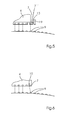
In
Es kann nun vorgesehen sein, dass der Roboter 5 und der daran aufgenommene Druckkopf 4 von seiner aktuellen Soll-Position abweicht und daher die Druckbahn A in einem Abstand zur Druckbahn B aufgebracht wird ober mit der Druckbahn B überlappt. In beiden Fällen kann es dabei zu sichtbaren und daher störenden Streifenbildungen an der Stelle 8 kommen. Solche Störungen können erfindungsgemäß jedoch verhindert werden. In den nachfolgenden
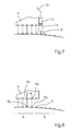
In
Konkretes und bevorzugtes Beispiel: Die Tropfengröße der Tropfen 9 (mittlerer Durchmesser) auf der Oberfläche 2 liegt bei etwa 100 Mikrometer. Der Mittenabstand der Tropfen 9 voneinander liegt ebenfalls bei etwa 100 Mikrometer. Die Variation der Auftreffpunkte und die Bahngenauigkeit des Roboters 5 liegen ebenfalls bei etwa 100 Mikrometer. Somit kann über die Erzeugung einer Sekundärbewegung in dieser Größenordnung die störende Streifenbildung reduziert oder verhindert werden.Specific and preferred example: The drop size of the drops 9 (average diameter) on the
In
Die Vibrationen des Piezo-Aktors 10 erzeugen Variationen der Auftreffpunkte der Tropfen bzw. der Druckpunkte 9. Diese Variationen können bevorzugt im bevorzugten Beispiel in der Größenordnungen 10 bis 100 Mikrometer liegen. Die Vibrationen können einem weißen Rauschen entsprechen. Die Vibrationen können auch über die Zeit periodisch sein, müssen dann allerdings in einem nicht ganzzahligen Verhältnis zur Taktfrequenz stehen, mit der die Druckpunkte 9 erzeugt werden.The vibrations of the
Die Amplitude der Störung des Druckkopfes 4 durch den Piezo-Aktor 10 entspricht der Amplitude der Variation des Auftreffpunkts der Tropfen, sofern die Sekundärbewegung 16 in der Ebene des Druckkopfes 4, z.B. dessen Unterseite liegt.The amplitude of the disturbance of the
Die in
Die Ausführungsform, welche in
Ein weiteres bevorzugtes Ausführungsbeispiel ist in
Eine alternative Lösung sieht vor, dass der Druckkopf beim Drucken im "multi-pass"-Betrieb bei verschiedenen Durchgängen mit verschiedenen Geschwindigkeiten bewegt wird, wodurch eine Sekundärbewegung infolge der Variation in der Flugbahn der Tropfen erzeugt wird.An alternative approach is to move the printhead in multi-pass printing at various speeds at various speeds, thereby producing secondary motion due to variation in the trajectory of the drops.
Gemäß einer weiteren alternativen Lösung werden beim Drucken im "multi-pass"-Betrieb im Bereich der Kante nicht alle Druckpunkte bei einem ersten Durchlauf gedruckt. Die Lücken zwischen den Druckpunkten des ersten Durchlaufs werden bei einem zweiten oder weiteren Durchläufen gefüllt. Druckbahn A und Druckbahn B greifen somit gewissermaßen ineinander und es gibt keine geraden Kanten zwischen ihnen.According to another alternative solution, when printing in "multi-pass" mode in the area of the edge, not all printing dots are printed on a first pass. The gaps between the pressure points of the first pass are filled in a second or further passes. Printing web A and printing web B thus effectively engage each other and there are no straight edges between them.
Claims (10)
dadurch gekennzeichnet,
dass die Vorrichtung (18) einen Piezo-Aktor (10) umfasst und die Sekundärbewegung (16) eine Bewegung des Tintenstrahl-Druckkopfs (4) ist.System according to claim 1,
characterized,
in that the device (18) comprises a piezoactuator (10) and the secondary movement (16) is a movement of the inkjet printhead (4).
dadurch gekennzeichnet,
dass die Vorrichtung (18) einen Piezo-Aktor (10) umfasst und die Sekundärbewegung (16) eine Bewegung wenigstens einer Düse (7) des Tintenstrahl-Druckkopfs (4) ist.System according to claim 1,
characterized,
in that the device (18) comprises a piezoactuator (10) and the secondary movement (16) is a movement of at least one nozzle (7) of the inkjet printhead (4).
dadurch gekennzeichnet,
dass die Vorrichtung (18) einen Piezo-Aktor (10) umfasst und die Sekundärbewegung (16) eine Bewegung wenigstens der Tropfen (9) einer Düse (7) des Tintenstrahl-Druckkopfs (4) ist.System according to claim 1,
characterized,
in that the device (18) comprises a piezoactuator (10) and the secondary movement (16) is a movement of at least the droplets (9) of a nozzle (7) of the inkjet printhead (4).
dadurch gekennzeichnet,
characterized,
dadurch gekennzeichnet,
characterized,
dadurch gekennzeichnet,
dass der Detektor einen optischer Sensor (13) oder einen Ultraschall-Sensor umfasst, welcher auf die Oberfläche (3) des Objekts (2) gerichtet ist.System according to claim 5,
characterized,
in that the detector comprises an optical sensor (13) or an ultrasonic sensor which is directed onto the surface (3) of the object (2).
dadurch gekennzeichnet,
dass der optische Sensor (13) auf bereits gedruckte Druckpunkte auf der Oberfläche (3) gerichtet ist und deren Fluoreszenzstrahlung erfasst.System according to claim 7,
characterized,
that the optical sensor (13) is directed to already printed pressure points on the surface (3) and detects their fluorescence radiation.
dadurch gekennzeichnet,
dass der Detektor (13) ein Tracking-System umfasst, welches die Position des Tintenstrahl-Druckkopfs (4) erfasst.System according to claim 5,
characterized,
in that the detector (13) comprises a tracking system which detects the position of the ink-jet printhead (4).
dadurch gekennzeichnet,
characterized,
Applications Claiming Priority (1)
| Application Number | Priority Date | Filing Date | Title |
|---|---|---|---|
| DE102012006370A DE102012006370A1 (en) | 2012-03-29 | 2012-03-29 | System for printing on an object |
Publications (3)
| Publication Number | Publication Date |
|---|---|
| EP2644392A2 true EP2644392A2 (en) | 2013-10-02 |
| EP2644392A3 EP2644392A3 (en) | 2013-11-13 |
| EP2644392B1 EP2644392B1 (en) | 2018-04-11 |
Family
ID=47900578
Family Applications (1)
| Application Number | Title | Priority Date | Filing Date |
|---|---|---|---|
| EP13156896.6A Not-in-force EP2644392B1 (en) | 2012-03-29 | 2013-02-27 | System for printing of an object |
Country Status (5)
| Country | Link |
|---|---|
| US (1) | US8882242B2 (en) |
| EP (1) | EP2644392B1 (en) |
| JP (1) | JP6157174B2 (en) |
| CN (1) | CN103358710B (en) |
| DE (1) | DE102012006370A1 (en) |
Cited By (21)
| Publication number | Priority date | Publication date | Assignee | Title |
|---|---|---|---|---|
| DE102013214980A1 (en) * | 2013-07-31 | 2015-02-05 | Krones Ag | Printing machine with printhead control |
| WO2016083078A1 (en) * | 2014-11-24 | 2016-06-02 | Heraeus Nobelight Gmbh | Method for producing a reflector on a reflector main part made of glass |
| WO2017084748A1 (en) * | 2015-11-20 | 2017-05-26 | Dürr Systems Ag | Coating method and corresponding coating installation |
| WO2017134193A1 (en) * | 2016-02-05 | 2017-08-10 | Schmidt E K Andreas | Printing method and printing device |
| EP3213823A1 (en) * | 2016-03-04 | 2017-09-06 | Exel Industries | Coating device, mutliaxial robot provided with such a coating device and corresponding coating method |
| WO2018108564A1 (en) * | 2016-12-14 | 2018-06-21 | Dürr Systems Ag | Push button for application of a coating agent on a component |
| WO2018108576A1 (en) * | 2016-12-14 | 2018-06-21 | Dürr Systems Ag | Printing head for the application of a coating medium |
| WO2019110422A1 (en) * | 2017-12-06 | 2019-06-13 | Robert Bosch Gmbh | Media application device |
| WO2019110418A1 (en) * | 2017-12-06 | 2019-06-13 | Robert Bosch Gmbh | Media application device |
| WO2019115108A1 (en) * | 2017-12-14 | 2019-06-20 | J. Wagner Gmbh | Method for operating a hand-controlled spraying device, and hand-controlled spraying device |
| NL2020542B1 (en) * | 2018-03-07 | 2019-09-13 | B A T Holding B V | Printing device and method for printing on a lateral surface of a rotationally symmetrical object |
| WO2020065208A1 (en) | 2018-09-28 | 2020-04-02 | Ivy Group Holding | Ink-jet printing module for printing robot, magazine for these modules, and ink-jet printing method using this robot |
| US10695784B2 (en) | 2015-11-20 | 2020-06-30 | Dürr Systems Ag | Coating apparatus having an intercepting device |
| US11154892B2 (en) | 2016-12-14 | 2021-10-26 | Dürr Systems Ag | Coating device for applying coating agent in a controlled manner |
| US11167302B2 (en) | 2016-12-14 | 2021-11-09 | Dürr Systems Ag | Coating device and associated operating method |
| US11203030B2 (en) | 2016-12-14 | 2021-12-21 | Dürr Systems Ag | Coating method and corresponding coating device |
| US11298717B2 (en) | 2016-12-14 | 2022-04-12 | Dürr Systems Ag | Print head having a temperature-control device |
| US11338312B2 (en) | 2016-12-14 | 2022-05-24 | Dürr Systems Ag | Print head and associated operating method |
| US11440035B2 (en) | 2016-12-14 | 2022-09-13 | Dürr Systems Ag | Application device and method for applying a multicomponent coating medium |
| US11504735B2 (en) | 2016-12-14 | 2022-11-22 | Dürr Systems Ag | Coating device having first and second printheads and corresponding coating process |
| US11944990B2 (en) | 2016-12-14 | 2024-04-02 | Dürr Systems Ag | Coating device for coating components |
Families Citing this family (40)
| Publication number | Priority date | Publication date | Assignee | Title |
|---|---|---|---|---|
| EP2873496A1 (en) * | 2013-11-18 | 2015-05-20 | ABB Technology AG | Printing system |
| DE102014221103A1 (en) * | 2013-11-19 | 2014-12-18 | Heidelberger Druckmaschinen Ag | A method of producing an imprint on an object having a curved surface |
| CN103692770B (en) * | 2013-12-04 | 2016-06-08 | 合肥海闻自动化设备有限公司 | The automatic tracing and detecting apparatus of printing press of a kind of special print heterotypic material |
| FI126677B (en) * | 2014-07-17 | 2017-03-31 | Johannes Vähänen | Spraying device, remote controlled tool and method for controlling the spraying direction of the device |
| DE102014012395A1 (en) * | 2014-08-21 | 2016-02-25 | Heidelberger Druckmaschinen Ag | Method and apparatus for printing a curved surface of an object with an ink jet head |
| NL2013931B1 (en) * | 2014-12-05 | 2016-10-11 | Spgprints B V | Method for manufacturing a printing bar unit for a printing system, and a printing bar unit. |
| WO2016111688A1 (en) * | 2015-01-08 | 2016-07-14 | Hewlett-Packard Development Company, L.P. | Mobile printers |
| WO2016122661A1 (en) * | 2015-01-30 | 2016-08-04 | Hewlett-Packard Development Company, L.P. | Mobile printing |
| DE102015202399A1 (en) | 2015-02-11 | 2016-08-11 | Heidelberger Druckmaschinen Ag | Apparatus for printing at least a portion of the surface of an object |
| US9452616B1 (en) * | 2015-05-29 | 2016-09-27 | The Boeing Company | System and method for printing an image on a surface |
| MX368235B (en) * | 2015-07-01 | 2019-09-25 | Volkswagen De Mexico S A De C V | Digital printing process of a vehicle body. |
| DE102017202195A1 (en) * | 2016-03-09 | 2017-09-14 | Heidelberger Druckmaschinen Ag | Multi-axis robot with drives, a tool head and a drag chain for guiding flexible cables |
| US10875045B2 (en) * | 2016-12-16 | 2020-12-29 | The Boeing Company | Variable cross-section compliance mechanism |
| JP6834765B2 (en) * | 2017-05-16 | 2021-02-24 | 株式会社リコー | Inkjet printer and 3D printing method |
| US10532561B2 (en) * | 2017-07-11 | 2020-01-14 | The Boeing Company | Metrology-based path planning for inkjet printing along a contoured surface |
| EP3676102A4 (en) * | 2017-08-31 | 2021-05-05 | MacDonald, Dettwiler and Associates Inc. | Robotic livery printing system |
| DE102017215437A1 (en) * | 2017-09-04 | 2019-03-07 | Krones Ag | Apparatus for printing on containers, printing machine and method for pivoting a printing module with a built-in printhead |
| DE102018213105A1 (en) * | 2017-09-05 | 2019-03-07 | Heidelberger Druckmaschinen Ag | Compensation pattern for failed pressure nozzles |
| DE102017218357B4 (en) * | 2017-10-13 | 2022-10-27 | BSH Hausgeräte GmbH | System for printing a component of a household appliance |
| DE102018103034A1 (en) * | 2018-02-12 | 2019-08-14 | Dr. Ing. H.C. F. Porsche Aktiengesellschaft | Print on a vehicle |
| FR3078900B1 (en) | 2018-03-15 | 2020-09-18 | Exel Ind | APPLICATION DEVICE FOR A FLUID PRODUCT WHOSE DOSING RATE DEPENDS ON THE SPEED OF AN OUTLET OF THE SAID FLUID PRODUCT |
| CN112020437B (en) * | 2018-05-15 | 2022-08-02 | 惠普发展公司,有限责任合伙企业 | Print head maintenance |
| DE102018210113B3 (en) | 2018-06-21 | 2019-07-11 | Heidelberger Druckmaschinen Ag | Ink-jet printing process for producing homogeneous-looking printed images on spherical bodies |
| FR3082780B1 (en) * | 2018-06-21 | 2020-07-24 | Reydel Automotive Bv | PRINTING OR COATING INSTALLATION OF SURFACES OF THREE-DIMENSIONAL PARTS |
| US10828889B2 (en) * | 2018-10-05 | 2020-11-10 | Southwest Research Institute | Printing using an externally generated reference |
| GB2579050B (en) * | 2018-11-16 | 2021-12-01 | Global Inkjet Systems Ltd | Control methods and systems |
| CN113382830A (en) * | 2019-02-12 | 2021-09-10 | 惠普发展公司,有限责任合伙企业 | Surface marking robot |
| US10940698B2 (en) * | 2019-02-22 | 2021-03-09 | Xyrec Ip B.V. | System and method for high accuracy printing on a 3D surface |
| DE102019004784A1 (en) | 2019-07-09 | 2020-01-09 | Daimler Ag | Method for printing an image on a three-dimensional free-form surface, and device designed to carry out such a method |
| DE102019119730A1 (en) * | 2019-07-22 | 2021-01-28 | Dr. Ing. H.C. F. Porsche Aktiengesellschaft | Pattern printing applicator and methods therefor |
| JP7204925B2 (en) | 2019-07-31 | 2023-01-16 | 京セラ株式会社 | Coating equipment and coating method |
| JPWO2021039292A1 (en) * | 2019-08-30 | 2021-03-04 | ||
| EP4023344A4 (en) | 2019-08-30 | 2023-08-23 | Kyocera Corporation | Painting device, painted film, and painting method |
| DE102019125844A1 (en) * | 2019-09-25 | 2021-03-25 | Krones Aktiengesellschaft | Container treatment machine for treating containers |
| JP7342727B2 (en) * | 2020-02-06 | 2023-09-12 | トヨタ車体株式会社 | Coating equipment, coating method and program |
| JP7010398B2 (en) * | 2021-02-04 | 2022-01-26 | 株式会社リコー | Control device and control method |
| DE102021108563A1 (en) | 2021-04-07 | 2022-10-13 | Dürr Systems Ag | Path correction method for a coating plant |
| EP4094947A3 (en) * | 2021-05-27 | 2023-03-08 | The Boeing Company | Printing system for generating nozzle firing patterns based on positional offsets |
| WO2023284967A1 (en) * | 2021-07-15 | 2023-01-19 | Abb Schweiz Ag | A method for controlling a printhead |
| WO2024046547A1 (en) * | 2022-08-30 | 2024-03-07 | Abb Schweiz Ag | Method of creating modified design on surface, control system and robot system |
Citations (5)
| Publication number | Priority date | Publication date | Assignee | Title |
|---|---|---|---|---|
| DE3140486A1 (en) | 1981-10-12 | 1982-05-06 | Jagenberg-Werke AG, 4000 Düsseldorf | DEVICE FOR COATING OBJECTS, LIKE GLASS BOTTLES, WITH PLASTIC |
| DE3737455A1 (en) | 1986-11-06 | 1988-05-19 | Westinghouse Electric Corp | DEVICE AND METHOD FOR PRODUCING COLOR PATTERNS |
| DE69005185T2 (en) | 1989-02-08 | 1994-04-28 | Canon Kk | Liquid jet recorder and method. |
| DE10202553A1 (en) | 2002-01-24 | 2003-08-07 | Burkhard Buestgens | Method of applying paints or varnishes |
| US20040036725A1 (en) | 2002-08-22 | 2004-02-26 | Kouji Ikeda | Ink jet recording apparatus |
Family Cites Families (20)
| Publication number | Priority date | Publication date | Assignee | Title |
|---|---|---|---|---|
| JPS61100805A (en) * | 1984-10-22 | 1986-05-19 | Kobe Steel Ltd | Device for correcting positional deviation of robot |
| DE3526769A1 (en) * | 1985-07-26 | 1987-01-29 | Schmalbach Lubeca | METHOD FOR DECORATING METAL OR PLASTIC CONTAINERS |
| JPS62188350A (en) * | 1986-02-14 | 1987-08-17 | Nec Ic Microcomput Syst Ltd | Lead frame |
| US4980839A (en) * | 1989-02-03 | 1990-12-25 | Matsushita Electric Industrial Co., Ltd. | Method for detecting original position of robot arm for alignment |
| JP3596095B2 (en) * | 1995-06-15 | 2004-12-02 | 豊田工機株式会社 | Robot controller |
| DE10031030B4 (en) | 2000-06-26 | 2005-08-04 | Bauer, Jörg R. | Method and device for producing flat components with a predetermined surface appearance and planar component, in particular front panel of a kitchen element |
| JP3995037B2 (en) * | 2001-11-28 | 2007-10-24 | 富士フイルム株式会社 | Scanning printing apparatus and printing method using the same |
| WO2003059631A1 (en) * | 2002-01-11 | 2003-07-24 | Brother Kogyo Kabushiki Kaisha | Image formation apparatus |
| JP4419015B2 (en) * | 2004-03-04 | 2010-02-24 | リコープリンティングシステムズ株式会社 | Inkjet coating method and apparatus |
| US7686414B2 (en) * | 2004-04-01 | 2010-03-30 | Hewlett-Packard Development Company, L.P. | Method of printing on large format flexible substrate and printing apparatus |
| EP1837189B1 (en) * | 2006-03-08 | 2016-10-12 | HOMAG GmbH | Device for refining of workpieces |
| ES2601398T3 (en) | 2006-03-08 | 2017-02-15 | Homag Holzbearbeitungssysteme Ag | Procedure and device for printing work pieces in plate form |
| JP4999505B2 (en) * | 2007-03-17 | 2012-08-15 | 株式会社リコー | Image forming apparatus and landing position deviation correction method |
| JP2011514234A (en) * | 2007-12-31 | 2011-05-06 | エグザテック・リミテッド・ライアビリティー・カンパニー | Apparatus and method for printing on a three-dimensional object |
| CN101952126A (en) * | 2007-12-31 | 2011-01-19 | 埃克阿泰克有限责任公司 | Method for printing high quality images on curved substrates |
| JP5564819B2 (en) * | 2009-04-03 | 2014-08-06 | セイコーエプソン株式会社 | Correction value calculation method and fluid ejection device manufacturing method |
| CN101722733B (en) * | 2009-11-19 | 2012-01-11 | 南开大学 | Three-dimensional spray-painting ink supply system |
| DE102010004496B4 (en) * | 2010-01-12 | 2020-06-18 | Hermann Müller | Method for operating a device for coating and / or printing a workpiece |
| JP5942403B2 (en) | 2011-12-06 | 2016-06-29 | セイコーエプソン株式会社 | Piezoelectric motor, drive device, electronic component inspection device, electronic component transport device, printing device, robot hand, and robot |
| JP5929138B2 (en) | 2011-12-06 | 2016-06-01 | セイコーエプソン株式会社 | Piezoelectric motors and robots |
-
2012
- 2012-03-29 DE DE102012006370A patent/DE102012006370A1/en not_active Withdrawn
-
2013
- 2013-02-27 EP EP13156896.6A patent/EP2644392B1/en not_active Not-in-force
- 2013-03-29 US US13/853,212 patent/US8882242B2/en not_active Expired - Fee Related
- 2013-03-29 CN CN201310106850.5A patent/CN103358710B/en not_active Expired - Fee Related
- 2013-03-29 JP JP2013071360A patent/JP6157174B2/en not_active Expired - Fee Related
Patent Citations (6)
| Publication number | Priority date | Publication date | Assignee | Title |
|---|---|---|---|---|
| DE3140486A1 (en) | 1981-10-12 | 1982-05-06 | Jagenberg-Werke AG, 4000 Düsseldorf | DEVICE FOR COATING OBJECTS, LIKE GLASS BOTTLES, WITH PLASTIC |
| DE3737455A1 (en) | 1986-11-06 | 1988-05-19 | Westinghouse Electric Corp | DEVICE AND METHOD FOR PRODUCING COLOR PATTERNS |
| DE69005185T2 (en) | 1989-02-08 | 1994-04-28 | Canon Kk | Liquid jet recorder and method. |
| DE10202553A1 (en) | 2002-01-24 | 2003-08-07 | Burkhard Buestgens | Method of applying paints or varnishes |
| DE10390349B4 (en) | 2002-01-24 | 2010-12-09 | Büstgens, Burkhard, Dr.-Ing. | Method and device for applying paints or varnishes |
| US20040036725A1 (en) | 2002-08-22 | 2004-02-26 | Kouji Ikeda | Ink jet recording apparatus |
Cited By (42)
| Publication number | Priority date | Publication date | Assignee | Title |
|---|---|---|---|---|
| DE102013214980A1 (en) * | 2013-07-31 | 2015-02-05 | Krones Ag | Printing machine with printhead control |
| US9327492B2 (en) | 2013-07-31 | 2016-05-03 | Krones Ag | Printing machine with print head control |
| US10322964B2 (en) | 2014-11-24 | 2019-06-18 | Heraeus Noblelight Gmbh | Method for producing a reflector on a reflector base made of glass |
| WO2016083078A1 (en) * | 2014-11-24 | 2016-06-02 | Heraeus Nobelight Gmbh | Method for producing a reflector on a reflector main part made of glass |
| US10493481B2 (en) | 2015-11-20 | 2019-12-03 | Dürr Systems Ag | Coating method and corresponding coating installation |
| US11278927B2 (en) | 2015-11-20 | 2022-03-22 | Dürr Systems Ag | Coating apparatus having an intercepting device and corresponding coating process |
| CN108698065A (en) * | 2015-11-20 | 2018-10-23 | 杜尔系统股份公司 | Painting method and corresponding coating equipment |
| US11192131B2 (en) | 2015-11-20 | 2021-12-07 | Dürr Systems Ag | Coating method and corresponding coating installation |
| CN108698065B (en) * | 2015-11-20 | 2021-11-09 | 杜尔系统股份公司 | Coating method and corresponding coating device |
| WO2017084748A1 (en) * | 2015-11-20 | 2017-05-26 | Dürr Systems Ag | Coating method and corresponding coating installation |
| US10695784B2 (en) | 2015-11-20 | 2020-06-30 | Dürr Systems Ag | Coating apparatus having an intercepting device |
| WO2017134193A1 (en) * | 2016-02-05 | 2017-08-10 | Schmidt E K Andreas | Printing method and printing device |
| US11084301B2 (en) | 2016-02-05 | 2021-08-10 | A. Schmidt e.K. | Printing method and printing device |
| EP3213823A1 (en) * | 2016-03-04 | 2017-09-06 | Exel Industries | Coating device, mutliaxial robot provided with such a coating device and corresponding coating method |
| FR3048368A1 (en) * | 2016-03-04 | 2017-09-08 | Exel Ind | COATING PRODUCT APPLICATOR, MULTIAXIS ROBOT COMPRISING SUCH APPLICATOR AND METHOD FOR APPLYING COATING PRODUCT |
| US11161134B2 (en) | 2016-03-04 | 2021-11-02 | Exel Industries | Applicator of coating product, multiaxis robot comprising such an applicator and application method of a coating product |
| US11203030B2 (en) | 2016-12-14 | 2021-12-21 | Dürr Systems Ag | Coating method and corresponding coating device |
| US11440035B2 (en) | 2016-12-14 | 2022-09-13 | Dürr Systems Ag | Application device and method for applying a multicomponent coating medium |
| US11944990B2 (en) | 2016-12-14 | 2024-04-02 | Dürr Systems Ag | Coating device for coating components |
| US11878317B2 (en) | 2016-12-14 | 2024-01-23 | Dürr Systems Ag | Coating device with printhead storage |
| CN110072630A (en) * | 2016-12-14 | 2019-07-30 | 杜尔系统股份公司 | Jet-printing head for being applied to coating agent on component |
| EP3698883A1 (en) * | 2016-12-14 | 2020-08-26 | Dürr Systems AG | Printing head for applying a coating material onto a workpiece |
| CN110072626A (en) * | 2016-12-14 | 2019-07-30 | 杜尔系统股份公司 | For applying the jet-printing head of coating agent |
| US11154892B2 (en) | 2016-12-14 | 2021-10-26 | Dürr Systems Ag | Coating device for applying coating agent in a controlled manner |
| US11813630B2 (en) | 2016-12-14 | 2023-11-14 | Dürr Systems Ag | Coating method and corresponding coating device |
| US11167302B2 (en) | 2016-12-14 | 2021-11-09 | Dürr Systems Ag | Coating device and associated operating method |
| US11167297B2 (en) | 2016-12-14 | 2021-11-09 | Dürr Systems Ag | Print head for the application of a coating agent |
| US11504735B2 (en) | 2016-12-14 | 2022-11-22 | Dürr Systems Ag | Coating device having first and second printheads and corresponding coating process |
| US11167308B2 (en) | 2016-12-14 | 2021-11-09 | Dürr Systems Ag | Print head for the application of a coating agent on a component |
| US11338312B2 (en) | 2016-12-14 | 2022-05-24 | Dürr Systems Ag | Print head and associated operating method |
| WO2018108576A1 (en) * | 2016-12-14 | 2018-06-21 | Dürr Systems Ag | Printing head for the application of a coating medium |
| WO2018108564A1 (en) * | 2016-12-14 | 2018-06-21 | Dürr Systems Ag | Push button for application of a coating agent on a component |
| US11298717B2 (en) | 2016-12-14 | 2022-04-12 | Dürr Systems Ag | Print head having a temperature-control device |
| CN110072630B (en) * | 2016-12-14 | 2022-05-03 | 杜尔系统股份公司 | Jet printing head for applying coating agent to parts |
| WO2019110422A1 (en) * | 2017-12-06 | 2019-06-13 | Robert Bosch Gmbh | Media application device |
| WO2019110418A1 (en) * | 2017-12-06 | 2019-06-13 | Robert Bosch Gmbh | Media application device |
| US11813620B2 (en) | 2017-12-14 | 2023-11-14 | J. Wagner Gmbh | Method of operating a hand-held spray device and hand-held spray device |
| WO2019115108A1 (en) * | 2017-12-14 | 2019-06-20 | J. Wagner Gmbh | Method for operating a hand-controlled spraying device, and hand-controlled spraying device |
| NL2020542B1 (en) * | 2018-03-07 | 2019-09-13 | B A T Holding B V | Printing device and method for printing on a lateral surface of a rotationally symmetrical object |
| US11745509B2 (en) | 2018-09-28 | 2023-09-05 | Westlake Compounds Holding | Ink-jet printing module for printing robot, magazine for these modules, and ink-jet printing method using this robot |
| FR3086575A1 (en) | 2018-09-28 | 2020-04-03 | Ivy Group Holding | INK JET PRINTING MODULE FOR PRINTING ROBOT, STORE FOR THESE MODULES, AND INK JET PRINTING METHOD USING THE SAME |
| WO2020065208A1 (en) | 2018-09-28 | 2020-04-02 | Ivy Group Holding | Ink-jet printing module for printing robot, magazine for these modules, and ink-jet printing method using this robot |
Also Published As
| Publication number | Publication date |
|---|---|
| CN103358710A (en) | 2013-10-23 |
| US20130257984A1 (en) | 2013-10-03 |
| US8882242B2 (en) | 2014-11-11 |
| JP6157174B2 (en) | 2017-07-05 |
| DE102012006370A1 (en) | 2013-10-02 |
| EP2644392B1 (en) | 2018-04-11 |
| EP2644392A3 (en) | 2013-11-13 |
| JP2013202781A (en) | 2013-10-07 |
| CN103358710B (en) | 2016-12-28 |
Similar Documents
| Publication | Publication Date | Title |
|---|---|---|
| EP2644392B1 (en) | System for printing of an object | |
| DE69932146T2 (en) | Correction system for droplet positioning errors in the printing direction axis in inkjet printers | |
| EP2832546B1 (en) | Printing machine with print head control | |
| DE60025582T2 (en) | Printer with simplified manufacturing process and manufacturing process | |
| DE69927330T2 (en) | Inkjet printhead calibration | |
| DE102005063486B3 (en) | Inkjet printing device | |
| DE60106185T2 (en) | METHOD AND DEVICE FOR CONTINUOUS INK JET PRESSURE | |
| EP3512707B1 (en) | Method and device for ink-jet application on sheet-type substrates | |
| DE102014221103A1 (en) | A method of producing an imprint on an object having a curved surface | |
| DE102014012395A1 (en) | Method and apparatus for printing a curved surface of an object with an ink jet head | |
| EP3208746A1 (en) | Method for inkjet printing of at least one curved area of the surface of an object | |
| DE102015218614A1 (en) | System and method for test pattern formation when printing 3D objects | |
| DE102019200354A1 (en) | Method for compensating defective printing nozzles in an inkjet printing machine | |
| DE102006045060A1 (en) | Method and apparatus for producing variable drop volume ink drops | |
| EP1990206B1 (en) | Method and device for embossing a component with two mutually inclined surface areas by means of a digital printing process | |
| DE3532437A1 (en) | INK-JET PRINTER WITH CORRECTION OF DROP DROP SPACING | |
| DE102018003096A1 (en) | Drop-on-demand - coating of surfaces | |
| DE102010038332B4 (en) | Coating process of at least one side surface of a tabular material | |
| DE102014108092A1 (en) | Direct printing machine for printing on containers | |
| DE2611282A1 (en) | INKJET PEN | |
| EP3538373B1 (en) | Method for printing a varying pattern of landing zones on a substrate by means of ink-jet printing | |
| EP2769848A2 (en) | Method for producing a printed image | |
| DE2628415A1 (en) | METHOD AND ARRANGEMENT FOR PREVENTING THE AERODYNAMIC DELAY OF INK JETS IN INK PRINTERS | |
| DE102012101432A1 (en) | Method for adjusting print heads in print head assembly of ink printing apparatus that is utilized for printing of paper web, involves adjusting correction value if deviation of actual distance from target distance of heads is identified | |
| DE3116412C2 (en) | Method and device for generating dots that are largely lined up without gaps with an inkjet printer |
Legal Events
| Date | Code | Title | Description |
|---|---|---|---|
| PUAI | Public reference made under article 153(3) epc to a published international application that has entered the european phase |
Free format text: ORIGINAL CODE: 0009012 |
|
| AK | Designated contracting states |
Kind code of ref document: A2 Designated state(s): AL AT BE BG CH CY CZ DE DK EE ES FI FR GB GR HR HU IE IS IT LI LT LU LV MC MK MT NL NO PL PT RO RS SE SI SK SM TR |
|
| AX | Request for extension of the european patent |
Extension state: BA ME |
|
| PUAL | Search report despatched |
Free format text: ORIGINAL CODE: 0009013 |
|
| AK | Designated contracting states |
Kind code of ref document: A3 Designated state(s): AL AT BE BG CH CY CZ DE DK EE ES FI FR GB GR HR HU IE IS IT LI LT LU LV MC MK MT NL NO PL PT RO RS SE SI SK SM TR |
|
| AX | Request for extension of the european patent |
Extension state: BA ME |
|
| RIC1 | Information provided on ipc code assigned before grant |
Ipc: B41J 3/407 20060101AFI20131004BHEP |
|
| RIC1 | Information provided on ipc code assigned before grant |
Ipc: B41J 3/407 20060101AFI20131015BHEP |
|
| 17P | Request for examination filed |
Effective date: 20140513 |
|
| RBV | Designated contracting states (corrected) |
Designated state(s): AL AT BE BG CH CY CZ DE DK EE ES FI FR GB GR HR HU IE IS IT LI LT LU LV MC MK MT NL NO PL PT RO RS SE SI SK SM TR |
|
| GRAP | Despatch of communication of intention to grant a patent |
Free format text: ORIGINAL CODE: EPIDOSNIGR1 |
|
| STAA | Information on the status of an ep patent application or granted ep patent |
Free format text: STATUS: GRANT OF PATENT IS INTENDED |
|
| INTG | Intention to grant announced |
Effective date: 20171011 |
|
| GRAS | Grant fee paid |
Free format text: ORIGINAL CODE: EPIDOSNIGR3 |
|
| GRAA | (expected) grant |
Free format text: ORIGINAL CODE: 0009210 |
|
| STAA | Information on the status of an ep patent application or granted ep patent |
Free format text: STATUS: THE PATENT HAS BEEN GRANTED |
|
| AK | Designated contracting states |
Kind code of ref document: B1 Designated state(s): AL AT BE BG CH CY CZ DE DK EE ES FI FR GB GR HR HU IE IS IT LI LT LU LV MC MK MT NL NO PL PT RO RS SE SI SK SM TR |
|
| REG | Reference to a national code |
Ref country code: GB Ref legal event code: FG4D Free format text: NOT ENGLISH |
|
| REG | Reference to a national code |
Ref country code: CH Ref legal event code: EP |
|
| REG | Reference to a national code |
Ref country code: AT Ref legal event code: REF Ref document number: 987590 Country of ref document: AT Kind code of ref document: T Effective date: 20180415 |
|
| REG | Reference to a national code |
Ref country code: IE Ref legal event code: FG4D Free format text: LANGUAGE OF EP DOCUMENT: GERMAN |
|
| REG | Reference to a national code |
Ref country code: DE Ref legal event code: R096 Ref document number: 502013009875 Country of ref document: DE |
|
| REG | Reference to a national code |
Ref country code: NL Ref legal event code: MP Effective date: 20180411 |
|
| REG | Reference to a national code |
Ref country code: LT Ref legal event code: MG4D |
|
| PG25 | Lapsed in a contracting state [announced via postgrant information from national office to epo] |
Ref country code: NL Free format text: LAPSE BECAUSE OF FAILURE TO SUBMIT A TRANSLATION OF THE DESCRIPTION OR TO PAY THE FEE WITHIN THE PRESCRIBED TIME-LIMIT Effective date: 20180411 |
|
| PG25 | Lapsed in a contracting state [announced via postgrant information from national office to epo] |
Ref country code: AL Free format text: LAPSE BECAUSE OF FAILURE TO SUBMIT A TRANSLATION OF THE DESCRIPTION OR TO PAY THE FEE WITHIN THE PRESCRIBED TIME-LIMIT Effective date: 20180411 Ref country code: ES Free format text: LAPSE BECAUSE OF FAILURE TO SUBMIT A TRANSLATION OF THE DESCRIPTION OR TO PAY THE FEE WITHIN THE PRESCRIBED TIME-LIMIT Effective date: 20180411 Ref country code: NO Free format text: LAPSE BECAUSE OF FAILURE TO SUBMIT A TRANSLATION OF THE DESCRIPTION OR TO PAY THE FEE WITHIN THE PRESCRIBED TIME-LIMIT Effective date: 20180711 Ref country code: FI Free format text: LAPSE BECAUSE OF FAILURE TO SUBMIT A TRANSLATION OF THE DESCRIPTION OR TO PAY THE FEE WITHIN THE PRESCRIBED TIME-LIMIT Effective date: 20180411 Ref country code: BG Free format text: LAPSE BECAUSE OF FAILURE TO SUBMIT A TRANSLATION OF THE DESCRIPTION OR TO PAY THE FEE WITHIN THE PRESCRIBED TIME-LIMIT Effective date: 20180711 Ref country code: LT Free format text: LAPSE BECAUSE OF FAILURE TO SUBMIT A TRANSLATION OF THE DESCRIPTION OR TO PAY THE FEE WITHIN THE PRESCRIBED TIME-LIMIT Effective date: 20180411 Ref country code: SE Free format text: LAPSE BECAUSE OF FAILURE TO SUBMIT A TRANSLATION OF THE DESCRIPTION OR TO PAY THE FEE WITHIN THE PRESCRIBED TIME-LIMIT Effective date: 20180411 Ref country code: PL Free format text: LAPSE BECAUSE OF FAILURE TO SUBMIT A TRANSLATION OF THE DESCRIPTION OR TO PAY THE FEE WITHIN THE PRESCRIBED TIME-LIMIT Effective date: 20180411 |
|
| PG25 | Lapsed in a contracting state [announced via postgrant information from national office to epo] |
Ref country code: GR Free format text: LAPSE BECAUSE OF FAILURE TO SUBMIT A TRANSLATION OF THE DESCRIPTION OR TO PAY THE FEE WITHIN THE PRESCRIBED TIME-LIMIT Effective date: 20180712 Ref country code: HR Free format text: LAPSE BECAUSE OF FAILURE TO SUBMIT A TRANSLATION OF THE DESCRIPTION OR TO PAY THE FEE WITHIN THE PRESCRIBED TIME-LIMIT Effective date: 20180411 Ref country code: LV Free format text: LAPSE BECAUSE OF FAILURE TO SUBMIT A TRANSLATION OF THE DESCRIPTION OR TO PAY THE FEE WITHIN THE PRESCRIBED TIME-LIMIT Effective date: 20180411 Ref country code: RS Free format text: LAPSE BECAUSE OF FAILURE TO SUBMIT A TRANSLATION OF THE DESCRIPTION OR TO PAY THE FEE WITHIN THE PRESCRIBED TIME-LIMIT Effective date: 20180411 |
|
| PG25 | Lapsed in a contracting state [announced via postgrant information from national office to epo] |
Ref country code: PT Free format text: LAPSE BECAUSE OF FAILURE TO SUBMIT A TRANSLATION OF THE DESCRIPTION OR TO PAY THE FEE WITHIN THE PRESCRIBED TIME-LIMIT Effective date: 20180813 |
|
| REG | Reference to a national code |
Ref country code: DE Ref legal event code: R097 Ref document number: 502013009875 Country of ref document: DE |
|
| RAP2 | Party data changed (patent owner data changed or rights of a patent transferred) |
Owner name: HEIDELBERGER DRUCKMASCHINEN AG |
|
| PG25 | Lapsed in a contracting state [announced via postgrant information from national office to epo] |
Ref country code: CZ Free format text: LAPSE BECAUSE OF FAILURE TO SUBMIT A TRANSLATION OF THE DESCRIPTION OR TO PAY THE FEE WITHIN THE PRESCRIBED TIME-LIMIT Effective date: 20180411 Ref country code: RO Free format text: LAPSE BECAUSE OF FAILURE TO SUBMIT A TRANSLATION OF THE DESCRIPTION OR TO PAY THE FEE WITHIN THE PRESCRIBED TIME-LIMIT Effective date: 20180411 Ref country code: SK Free format text: LAPSE BECAUSE OF FAILURE TO SUBMIT A TRANSLATION OF THE DESCRIPTION OR TO PAY THE FEE WITHIN THE PRESCRIBED TIME-LIMIT Effective date: 20180411 Ref country code: EE Free format text: LAPSE BECAUSE OF FAILURE TO SUBMIT A TRANSLATION OF THE DESCRIPTION OR TO PAY THE FEE WITHIN THE PRESCRIBED TIME-LIMIT Effective date: 20180411 Ref country code: DK Free format text: LAPSE BECAUSE OF FAILURE TO SUBMIT A TRANSLATION OF THE DESCRIPTION OR TO PAY THE FEE WITHIN THE PRESCRIBED TIME-LIMIT Effective date: 20180411 |
|
| PLBE | No opposition filed within time limit |
Free format text: ORIGINAL CODE: 0009261 |
|
| STAA | Information on the status of an ep patent application or granted ep patent |
Free format text: STATUS: NO OPPOSITION FILED WITHIN TIME LIMIT |
|
| PG25 | Lapsed in a contracting state [announced via postgrant information from national office to epo] |
Ref country code: SM Free format text: LAPSE BECAUSE OF FAILURE TO SUBMIT A TRANSLATION OF THE DESCRIPTION OR TO PAY THE FEE WITHIN THE PRESCRIBED TIME-LIMIT Effective date: 20180411 |
|
| 26N | No opposition filed |
Effective date: 20190114 |
|
| PG25 | Lapsed in a contracting state [announced via postgrant information from national office to epo] |
Ref country code: SI Free format text: LAPSE BECAUSE OF FAILURE TO SUBMIT A TRANSLATION OF THE DESCRIPTION OR TO PAY THE FEE WITHIN THE PRESCRIBED TIME-LIMIT Effective date: 20180411 |
|
| REG | Reference to a national code |
Ref country code: CH Ref legal event code: PL |
|
| PG25 | Lapsed in a contracting state [announced via postgrant information from national office to epo] |
Ref country code: LU Free format text: LAPSE BECAUSE OF NON-PAYMENT OF DUE FEES Effective date: 20190227 Ref country code: MC Free format text: LAPSE BECAUSE OF FAILURE TO SUBMIT A TRANSLATION OF THE DESCRIPTION OR TO PAY THE FEE WITHIN THE PRESCRIBED TIME-LIMIT Effective date: 20180411 |
|
| REG | Reference to a national code |
Ref country code: BE Ref legal event code: MM Effective date: 20190228 |
|
| REG | Reference to a national code |
Ref country code: IE Ref legal event code: MM4A |
|
| PG25 | Lapsed in a contracting state [announced via postgrant information from national office to epo] |
Ref country code: LI Free format text: LAPSE BECAUSE OF NON-PAYMENT OF DUE FEES Effective date: 20190228 Ref country code: CH Free format text: LAPSE BECAUSE OF NON-PAYMENT OF DUE FEES Effective date: 20190228 |
|
| PG25 | Lapsed in a contracting state [announced via postgrant information from national office to epo] |
Ref country code: IE Free format text: LAPSE BECAUSE OF NON-PAYMENT OF DUE FEES Effective date: 20190227 |
|
| PG25 | Lapsed in a contracting state [announced via postgrant information from national office to epo] |
Ref country code: BE Free format text: LAPSE BECAUSE OF NON-PAYMENT OF DUE FEES Effective date: 20190228 |
|
| PG25 | Lapsed in a contracting state [announced via postgrant information from national office to epo] |
Ref country code: TR Free format text: LAPSE BECAUSE OF FAILURE TO SUBMIT A TRANSLATION OF THE DESCRIPTION OR TO PAY THE FEE WITHIN THE PRESCRIBED TIME-LIMIT Effective date: 20180411 |
|
| REG | Reference to a national code |
Ref country code: AT Ref legal event code: MM01 Ref document number: 987590 Country of ref document: AT Kind code of ref document: T Effective date: 20190227 |
|
| PG25 | Lapsed in a contracting state [announced via postgrant information from national office to epo] |
Ref country code: AT Free format text: LAPSE BECAUSE OF NON-PAYMENT OF DUE FEES Effective date: 20190227 |
|
| PG25 | Lapsed in a contracting state [announced via postgrant information from national office to epo] |
Ref country code: MT Free format text: LAPSE BECAUSE OF FAILURE TO SUBMIT A TRANSLATION OF THE DESCRIPTION OR TO PAY THE FEE WITHIN THE PRESCRIBED TIME-LIMIT Effective date: 20180411 |
|
| PGFP | Annual fee paid to national office [announced via postgrant information from national office to epo] |
Ref country code: IT Payment date: 20210226 Year of fee payment: 9 Ref country code: FR Payment date: 20210223 Year of fee payment: 9 |
|
| PG25 | Lapsed in a contracting state [announced via postgrant information from national office to epo] |
Ref country code: CY Free format text: LAPSE BECAUSE OF FAILURE TO SUBMIT A TRANSLATION OF THE DESCRIPTION OR TO PAY THE FEE WITHIN THE PRESCRIBED TIME-LIMIT Effective date: 20180411 |
|
| PGFP | Annual fee paid to national office [announced via postgrant information from national office to epo] |
Ref country code: GB Payment date: 20210219 Year of fee payment: 9 Ref country code: DE Payment date: 20210228 Year of fee payment: 9 |
|
| PG25 | Lapsed in a contracting state [announced via postgrant information from national office to epo] |
Ref country code: IS Free format text: LAPSE BECAUSE OF FAILURE TO SUBMIT A TRANSLATION OF THE DESCRIPTION OR TO PAY THE FEE WITHIN THE PRESCRIBED TIME-LIMIT Effective date: 20180811 |
|
| PG25 | Lapsed in a contracting state [announced via postgrant information from national office to epo] |
Ref country code: HU Free format text: LAPSE BECAUSE OF FAILURE TO SUBMIT A TRANSLATION OF THE DESCRIPTION OR TO PAY THE FEE WITHIN THE PRESCRIBED TIME-LIMIT; INVALID AB INITIO Effective date: 20130227 |
|
| PG25 | Lapsed in a contracting state [announced via postgrant information from national office to epo] |
Ref country code: MK Free format text: LAPSE BECAUSE OF FAILURE TO SUBMIT A TRANSLATION OF THE DESCRIPTION OR TO PAY THE FEE WITHIN THE PRESCRIBED TIME-LIMIT Effective date: 20180411 |
|
| REG | Reference to a national code |
Ref country code: DE Ref legal event code: R119 Ref document number: 502013009875 Country of ref document: DE |
|
| GBPC | Gb: european patent ceased through non-payment of renewal fee |
Effective date: 20220227 |
|
| PG25 | Lapsed in a contracting state [announced via postgrant information from national office to epo] |
Ref country code: FR Free format text: LAPSE BECAUSE OF NON-PAYMENT OF DUE FEES Effective date: 20220228 |
|
| PG25 | Lapsed in a contracting state [announced via postgrant information from national office to epo] |
Ref country code: GB Free format text: LAPSE BECAUSE OF NON-PAYMENT OF DUE FEES Effective date: 20220227 Ref country code: DE Free format text: LAPSE BECAUSE OF NON-PAYMENT OF DUE FEES Effective date: 20220901 |
|
| PG25 | Lapsed in a contracting state [announced via postgrant information from national office to epo] |
Ref country code: IT Free format text: LAPSE BECAUSE OF NON-PAYMENT OF DUE FEES Effective date: 20220227 |
|
| P01 | Opt-out of the competence of the unified patent court (upc) registered |
Effective date: 20230403 |