EP2643702B1 - Resonant biaxial accelerometer structure of the microelectromechanical type - Google Patents
Resonant biaxial accelerometer structure of the microelectromechanical type Download PDFInfo
- Publication number
- EP2643702B1 EP2643702B1 EP11799844.3A EP11799844A EP2643702B1 EP 2643702 B1 EP2643702 B1 EP 2643702B1 EP 11799844 A EP11799844 A EP 11799844A EP 2643702 B1 EP2643702 B1 EP 2643702B1
- Authority
- EP
- European Patent Office
- Prior art keywords
- inertial mass
- resonant
- elastic elements
- detection
- elements
- Prior art date
- Legal status (The legal status is an assumption and is not a legal conclusion. Google has not performed a legal analysis and makes no representation as to the accuracy of the status listed.)
- Active
Links
- 238000001514 detection method Methods 0.000 claims description 77
- 230000001133 acceleration Effects 0.000 claims description 56
- 239000000758 substrate Substances 0.000 claims description 23
- 230000002093 peripheral effect Effects 0.000 claims description 6
- 230000004044 response Effects 0.000 claims description 5
- 230000035945 sensitivity Effects 0.000 description 14
- 230000035882 stress Effects 0.000 description 14
- 238000000034 method Methods 0.000 description 9
- 230000005484 gravity Effects 0.000 description 8
- 230000000694 effects Effects 0.000 description 7
- 238000005259 measurement Methods 0.000 description 7
- 238000005459 micromachining Methods 0.000 description 6
- 238000013519 translation Methods 0.000 description 6
- XUIMIQQOPSSXEZ-UHFFFAOYSA-N Silicon Chemical compound [Si] XUIMIQQOPSSXEZ-UHFFFAOYSA-N 0.000 description 5
- 239000000463 material Substances 0.000 description 5
- 230000008569 process Effects 0.000 description 5
- 229910052710 silicon Inorganic materials 0.000 description 5
- 239000010703 silicon Substances 0.000 description 5
- 230000009471 action Effects 0.000 description 4
- 230000008901 benefit Effects 0.000 description 4
- 239000004065 semiconductor Substances 0.000 description 4
- 230000003321 amplification Effects 0.000 description 3
- 238000005452 bending Methods 0.000 description 3
- 238000000151 deposition Methods 0.000 description 3
- 230000008021 deposition Effects 0.000 description 3
- 238000006073 displacement reaction Methods 0.000 description 3
- 238000005516 engineering process Methods 0.000 description 3
- 238000003199 nucleic acid amplification method Methods 0.000 description 3
- 238000000059 patterning Methods 0.000 description 3
- 230000009467 reduction Effects 0.000 description 3
- 238000004626 scanning electron microscopy Methods 0.000 description 3
- 230000008859 change Effects 0.000 description 2
- 230000008878 coupling Effects 0.000 description 2
- 238000010168 coupling process Methods 0.000 description 2
- 238000005859 coupling reaction Methods 0.000 description 2
- 230000006355 external stress Effects 0.000 description 2
- 238000004519 manufacturing process Methods 0.000 description 2
- 230000010355 oscillation Effects 0.000 description 2
- 229910021420 polycrystalline silicon Inorganic materials 0.000 description 2
- 229920005591 polysilicon Polymers 0.000 description 2
- 230000000284 resting effect Effects 0.000 description 2
- 238000012360 testing method Methods 0.000 description 2
- 230000000930 thermomechanical effect Effects 0.000 description 2
- 230000002238 attenuated effect Effects 0.000 description 1
- 238000003486 chemical etching Methods 0.000 description 1
- 239000000470 constituent Substances 0.000 description 1
- 238000010586 diagram Methods 0.000 description 1
- 238000005530 etching Methods 0.000 description 1
- 230000005284 excitation Effects 0.000 description 1
- 238000010438 heat treatment Methods 0.000 description 1
- 230000003993 interaction Effects 0.000 description 1
- 238000005304 joining Methods 0.000 description 1
- 230000007246 mechanism Effects 0.000 description 1
- 238000001465 metallisation Methods 0.000 description 1
- 238000012986 modification Methods 0.000 description 1
- 230000004048 modification Effects 0.000 description 1
- 238000012544 monitoring process Methods 0.000 description 1
- 230000003647 oxidation Effects 0.000 description 1
- 238000007254 oxidation reaction Methods 0.000 description 1
- 238000012545 processing Methods 0.000 description 1
- 238000004088 simulation Methods 0.000 description 1
Images


Classifications
-
- G—PHYSICS
- G01—MEASURING; TESTING
- G01P—MEASURING LINEAR OR ANGULAR SPEED, ACCELERATION, DECELERATION, OR SHOCK; INDICATING PRESENCE, ABSENCE, OR DIRECTION, OF MOVEMENT
- G01P15/00—Measuring acceleration; Measuring deceleration; Measuring shock, i.e. sudden change of acceleration
- G01P15/02—Measuring acceleration; Measuring deceleration; Measuring shock, i.e. sudden change of acceleration by making use of inertia forces using solid seismic masses
- G01P15/08—Measuring acceleration; Measuring deceleration; Measuring shock, i.e. sudden change of acceleration by making use of inertia forces using solid seismic masses with conversion into electric or magnetic values
- G01P15/097—Measuring acceleration; Measuring deceleration; Measuring shock, i.e. sudden change of acceleration by making use of inertia forces using solid seismic masses with conversion into electric or magnetic values by vibratory elements
-
- G—PHYSICS
- G01—MEASURING; TESTING
- G01P—MEASURING LINEAR OR ANGULAR SPEED, ACCELERATION, DECELERATION, OR SHOCK; INDICATING PRESENCE, ABSENCE, OR DIRECTION, OF MOVEMENT
- G01P15/00—Measuring acceleration; Measuring deceleration; Measuring shock, i.e. sudden change of acceleration
- G01P15/02—Measuring acceleration; Measuring deceleration; Measuring shock, i.e. sudden change of acceleration by making use of inertia forces using solid seismic masses
- G01P15/08—Measuring acceleration; Measuring deceleration; Measuring shock, i.e. sudden change of acceleration by making use of inertia forces using solid seismic masses with conversion into electric or magnetic values
- G01P15/0888—Measuring acceleration; Measuring deceleration; Measuring shock, i.e. sudden change of acceleration by making use of inertia forces using solid seismic masses with conversion into electric or magnetic values for indicating angular acceleration
-
- G—PHYSICS
- G01—MEASURING; TESTING
- G01P—MEASURING LINEAR OR ANGULAR SPEED, ACCELERATION, DECELERATION, OR SHOCK; INDICATING PRESENCE, ABSENCE, OR DIRECTION, OF MOVEMENT
- G01P15/00—Measuring acceleration; Measuring deceleration; Measuring shock, i.e. sudden change of acceleration
- G01P15/18—Measuring acceleration; Measuring deceleration; Measuring shock, i.e. sudden change of acceleration in two or more dimensions
-
- G—PHYSICS
- G01—MEASURING; TESTING
- G01P—MEASURING LINEAR OR ANGULAR SPEED, ACCELERATION, DECELERATION, OR SHOCK; INDICATING PRESENCE, ABSENCE, OR DIRECTION, OF MOVEMENT
- G01P15/00—Measuring acceleration; Measuring deceleration; Measuring shock, i.e. sudden change of acceleration
- G01P15/02—Measuring acceleration; Measuring deceleration; Measuring shock, i.e. sudden change of acceleration by making use of inertia forces using solid seismic masses
- G01P15/08—Measuring acceleration; Measuring deceleration; Measuring shock, i.e. sudden change of acceleration by making use of inertia forces using solid seismic masses with conversion into electric or magnetic values
- G01P2015/0805—Measuring acceleration; Measuring deceleration; Measuring shock, i.e. sudden change of acceleration by making use of inertia forces using solid seismic masses with conversion into electric or magnetic values being provided with a particular type of spring-mass-system for defining the displacement of a seismic mass due to an external acceleration
- G01P2015/0808—Measuring acceleration; Measuring deceleration; Measuring shock, i.e. sudden change of acceleration by making use of inertia forces using solid seismic masses with conversion into electric or magnetic values being provided with a particular type of spring-mass-system for defining the displacement of a seismic mass due to an external acceleration for defining in-plane movement of the mass, i.e. movement of the mass in the plane of the substrate
- G01P2015/082—Measuring acceleration; Measuring deceleration; Measuring shock, i.e. sudden change of acceleration by making use of inertia forces using solid seismic masses with conversion into electric or magnetic values being provided with a particular type of spring-mass-system for defining the displacement of a seismic mass due to an external acceleration for defining in-plane movement of the mass, i.e. movement of the mass in the plane of the substrate for two degrees of freedom of movement of a single mass
Definitions
- the present invention relates to a resonant biaxial accelerometer structure of a MEMS (microelectromechanical system) type, in particular capable of detecting with high electrical performance two independent components of acceleration in a plane.
- MEMS microelectromechanical system
- MEMS accelerometers are currently used, thanks to their extremely compact dimensions, low levels of consumption, and good electrical performance, in a wide range of fields of application, amongst which the automotive industry, monitoring of vibrations, and portable electronics.
- MEMS accelerometers proposed in the literature and currently present on the market can be generally grouped into three classes, on the basis of the principle of detection used by the corresponding microelectromechanical detection structure: capacitive, resonant, and piezoresistive.
- the external acceleration to be measured produces a detectable shift of the resonance frequency of the microelectromechanical structure, or of some part thereof.
- the resonant detection as compared to other measurement principles, presents the advantage of offering a direct frequency output, high sensitivity, and wide dynamic range.
- the external acceleration is detected in terms of a shift in the resonance frequency of a resonant element, in general beam-shaped, coupled to an inertial mass (the so-called “proof mass” or “free mass”).
- a and I are, respectively, the length, the area of the cross section, and the moment of inertia of the resonant element
- ⁇ is the mass density of the material of which it is made
- E is the elastic modulus
- c and ⁇ are coefficients, the value of which depends, in a known way, upon the conditions of constraint of the beam that constitutes said resonant element.
- the various MEMS resonant accelerometers so far proposed differ from the standpoint of the geometries envisaged for the microelectromechanical detection structure (in particular for the different arrangements of the resonant element with respect to the inertial mass), and consequently for the electrical characteristics that derive therefrom, for example as regards the amplification of the axial force and consequently the sensitivity in the detection of acceleration.
- the sensitivity of resonant accelerometers is generally defined as the variation in frequency generated by an external acceleration the equal to 1g.
- Known resonant accelerometers obtained through techniques of surface micromachining typically have a sensitivity that starts from some tens of Hz/g and does not exceed 200 Hz/g, and, at least some of them, have rather large dimensions.
- the MEMS resonant accelerometers proposed so far are for the most part of a uniaxial type, i.e., able to detect, with a single inertial detection mass, a single component of acceleration directed along a given axis of detection. Consequently, it is necessary to replicate the microelectromechanical structures proposed, each provided with a corresponding inertial mass, to obtain a detection of components of acceleration directed along a number of axes of detection.
- US 4 851 080 A discloses a resonant accelerometer, including a mass suspended by pairs of resonating arms. One pair of arms lies on a first axis through the mass. Another pair of arms lies on a second axis through the mass, perpendicular to the first axis. Acceleration of the mass is detected by a measured change in resonant frequency of the arms of a pair. The resonating arms are directly attached to the mass.
- US 2006/096378 A1 discloses a uni-axial accelerometer structure, including a moveable seismic mass capable of moving translationally along a sensitive axis under the effect of an acceleration, and a resonator that can vibrate and be subjected to a tensile or compressive force depending on the direction of the acceleration.
- the resonator is placed symmetrically with respect to an axis of symmetry of the structure, this axis being parallel to the sensitive axis and passing through the center of gravity of the seismic mass.
- the structure further includes amplification means for amplifying the acceleration force, which comprise two rigid terminations of the resonator and two pairs of micromachined elastic arms, coupled to each rigid termination, and arranged at an angle with respect to the sensitive axis.
- US 6 389 898 B1 discloses a microsensor with a resonator structure, which is excited by first electrical signals to oscillate, and emits second electrical signals in dependence on the measuring variable; a heating element, supplied with at least one of the first electrical signals, is arranged on the resonator structure for the thermal excitations of oscillations.
- the aim of the present invention is consequently to provide a microelectromechanical structure for a resonant accelerometer that will present improved physical and electrical characteristics, and in particular that will enable a biaxial detection of components of accelerations acting along at least two axes of detection in a plane.
- a microelectromechanical structure for a resonant accelerometer is consequently provided, as defined in the annexed claims.
- one aspect of the present invention envisages the use of a single inertial mass for the detection of at least two independent components of acceleration in a plane, in particular coinciding with a plane of main extension of said inertial mass.
- a single inertial mass for the detection of at least two independent components of acceleration in a plane, in particular coinciding with a plane of main extension of said inertial mass.
- resonant elements for detecting the aforesaid components of acceleration according to the principle of the variation of the resonance frequency (see in this regard the foregoing description).
- Figure 1 shows a first embodiment of a microelectromechanical detection structure, designated as a whole by 1, of a resonant biaxial accelerometer.
- the microelectromechanical detection structure 1 is produced in an integrated way, with the surface-micromachining semiconductor techniques, in particular starting from a body made of semiconductor material (such as silicon).
- the microelectromechanical detection structure 1 comprises a single inertial mass 2, which has, for example, a generically square shape in a plane xy, corresponding to a principal plane of extension of its own, defined by a first axis x and by a second axis y, which correspond moreover to the directions of detection of the resonant biaxial accelerometer (as will be clarified hereinafter).
- the inertial mass 2 has a negligible dimension in the direction orthogonal to said plane xy, along a third axis z, which defines, with the aforesaid first and second axes x, y, a set of three orthogonal axes.
- the inertial mass 2 has, in said first embodiment, four portions of mass 2a- 2d, which have, for example, a substantially square shape in the plane xy and define an external boundary of the mass in said plane xy, and a central portion 2e, which radiuses the portions of mass 2a-2d at the centre and has also, for example, a substantially square shape in plan view.
- the inertial mass 2 moreover has a centroidal axis (defined as the axis passing through its centre of gravity G, in this case coinciding with the geometrical centre of the central portion 2e), which moreover represents an axis of symmetry for the microelectromechanical detection structure 1 and is directed orthogonal to the plane xy.
- the portions of mass 2a-2d define, in adjacent pairs, respective windows 4, numbering four in all, which extend starting from the central portion 2e and open towards the outside of the inertial mass 2.
- windows 4 of a first pair extend from opposite sides of the central portion 2e along the second axis y
- the remaining windows 4 extend along the first axis x, and are also set on opposite sides of the central portion 2e.
- the structure of the inertial mass 2 is symmetrical with respect to axes parallel to the axes x and y and passing through the geometrical centre of the central portion 2e (centre of gravity G).
- the inertial mass 2 is anchored to a substrate (not illustrated, for example a substrate made of semiconductor material, such as silicon) so as to be suspended above said substrate, with the plane xy substantially parallel to a top surface of said substrate.
- a substrate not illustrated, for example a substrate made of semiconductor material, such as silicon
- the inertial mass 2 is elastically coupled to first anchorages 6, numbering four in all in the first embodiment illustrated, set externally to said inertial mass 2, and aligned in pairs to the windows 4 in the direction of the prolongation of said windows 4, along the first axis x or the second axis y.
- the first anchorages 6 are for example constituted by pillars that extend as far as, and are mechanically connected to, the substrate.
- the inertial mass 2 is connected to the aforesaid first anchorages 6 by means of respective elastic elements 8 (which are also four in number in the embodiment illustrated), as a whole configured so as to maintain the inertial mass 2 suspended above the substrate and enable at least one first linear movement of translation and one second linear movement of translation thereof (with respect to said substrate), respectively along the first axis x and the second axis y, and as to prevent movements thereof out of said plane xy.
- Each elastic element 8 comprises: a first portion 8a, constituted by a rectilinear linear spring (the so-called “single beam”), which extends along the first axis x or second axis y starting from an external lateral surface of the central portion 2e of the inertial mass 2 (centrally with respect thereto), within a respective window 4; a second portion 8b, connected to the first portion 8a, and constituted by a folded spring (the so-called “folded beam”), having extension in a direction transverse to the first portion 8a, in particular along the second axis y or first axis x (the second portion 8b is hence constituted by a plurality of rectilinear springs, parallel to one another, which have main extension in the aforesaid transverse direction and are radiused to one another at the corresponding ends); and a third portion 8c, connected to the second portion 8b and constituted once again by a rectilinear spring, having extension along the first axis
- the elastic elements 8 are very thin (the corresponding constituent portions have, that is, a length in the direction of extension much greater than the corresponding width).
- the microelectromechanical detection structure 1 further comprises a resonant part, formed by four resonant elements 10a-10d, each of which is constituted by a thin resonant beam.
- the resonant elements 10a-10d are set externally to the inertial mass 2, with respect to the plane xy, and extend parallel in pairs along the first axis x or the second axis y, moreover parallel to the second portion 8b of an associated elastic element 8, externally thereto.
- each resonant element 10a-10d is rigidly constrained to the substrate at a first end thereof, by means of a respective second anchorage 12 (once again constituted, for example, by a pillar that extends as far as, and is connected to, the substrate), and extends starting from said second anchorage 12 until it joins, with a second end of its own, a respective elastic element 8, in particular the third portion 8c of said elastic element 8, in close proximity of the respective first anchorage 6 of said elastic element 8.
- the point of connection of the resonant element 10a-10d to the respective elastic element 8 is designated by c.
- Each resonant element 10a-10d hence forms with the part of the third portion 8c of the respective elastic element 8, comprised between the point of connection c and the corresponding first anchorage 6, an L-shaped resonant structure.
- Each resonant element 10a-10d is hence mechanically coupled to the inertial mass 2 through a respective elastic element 8.
- said configuration enables high values of detection sensitivity to be obtained with an inertial mass 2 of contained dimensions in so far as the intermediate presence of the elastic elements 8 prevents the stiffness of the resonant elements 10a-10d from hindering directly the inertial mass 2 and hence reducing the excursion of the movements thereof upon detection of the external accelerations.
- the position of the point of connection c in the close proximity of the first anchorages 6 is a factor that determines the electrical characteristics of the resonant detection structure (in terms of amplification of the axial force in response to an external acceleration, and hence of the detection sensitivity).
- the configuration described of the resonant elements 10a-10d moreover advantageously enables increase in the interval of linear behaviour in frequency of the microelectromechanical detection structure 1.
- the presence of the part of the third portion 8c of the elastic elements 8, comprised between the point of connection c and the corresponding first anchorage 6, of small dimensions causes the linear behaviour of each resonant element 10a-10d not to depart substantially from that of standard resonators constrained at both ends (the so-called "double-clamped" resonators), while the non-linear behaviour is instead considerably improved.
- the microelectromechanical detection structure 1 further comprises, for each resonant element 10a-10d, a pair of electrodes 13, 14, arranged parallel to one another and parallel to the corresponding resonant element 10a- 10d, on opposite sides of said resonant element 10a- 10d with respect to the first axis x or second axis y.
- a first electrode 13 is used to send the associated resonant element 10a-10d into a resonance condition by applying an appropriate difference of electrical potential
- a second electrode 14 is used as detection electrode, for detecting, by means of a variation of the capacitive coupling with the resonant element 10a-10d, variations of the corresponding resonance frequency (according to a detection scheme known as "parallel plate").
- the electrodes 13 and 14 have an encumbrance along the corresponding direction of extension that is advantageously contained between a second anchorage 12 and the third portion 8c of the facing elastic element 8.
- appropriate electrical-connection paths are envisaged for the electrical connection of the aforesaid electrodes 13, 14 to an electronic circuit coupled to the microelectromechanical detection structure 1.
- Said electronic circuit is configured so as to supply the electrical signals of actuation to the microelectromechanical detection structure 1, and receive and process the electrical detection signals supplied by said microelectromechanical detection structure 1.
- FIGS. 2a-2c illustrate possible deformations thereof in response to different external stresses, and in particular in response to: a first, linear, acceleration acting along the first axis x ( Figure 2a ); a second, linear, acceleration acting along the second axis y ( Figure 2b ); and a third, angular, acceleration acting about the centroidal axis, or, in an equivalent way, about the third axis z.
- the arrangement of the elastic elements 8 enables in fact three movements of the inertial mass 2 in the plane xy (a first translation and a second translation, respectively along the first axis x and the second axis y, and moreover a rotation about the third axis z); the effects of said movements on the resonant elements 10a-10d can be decoupled in such a way as to enable detection of the corresponding components of acceleration individually and without mutual interference.
- the four resonant elements 10a-10d have the same nominal frequency of resonance f 0 , as a result of the interaction with the corresponding first electrodes 13 and the associated electronic circuit.
- the inertial mass 2 When the inertial mass 2 is subjected to a first acceleration a x along the first axis x (in the direction of the arrow in Figure 2a ), the inertial mass 2 translates as a whole along said first axis x, as a result of the bending of the second (folded) portion 8b of a first pair of the elastic elements 8, and moreover of the bending of the first (linear) portion 8a of the remaining elastic elements 8 (in general, there occurs the bending of the springs with extension transverse to the direction of displacement, in this case with extension along the second axis y, whilst the springs with extension along the first axis x do not undergo an appreciable axial deformation).
- the movement of translation of the inertial mass 2 along the first axis x consequently causes, evidently, an compressive stress - N 1 on a first resonant element 10a of the pair of resonant elements arranged along the first axis x, and a tensile stress N 1 , having the same intensity, on the second resonant element 10c of said pair; in particular, the movement of the inertial mass 2 is transmitted to the resonant elements 10a, 10c by the respective elastic elements 8, at the point of connection c, the position of which is substantially constrained.
- the resonance frequency of the first resonant element 10a designated by f 1
- the resonance frequency of the second resonant element 10c of the pair designated by f 2
- the resonant elements 10b, 10d of the other pair of resonant elements arranged along the second axis y are, instead, substantially not loaded and not subject to axial stresses with respect to the resting condition, in the presence of said first external acceleration a x .
- a second acceleration a y acting along the second axis y determines an overall displacement of the inertial mass 2 along the second axis y (in the direction indicated by the arrow in Figure 2b ).
- the movement of translation of the inertial mass 2 along the second axis y causes in this case a compressive stress - N 2 (with N 2 that can be equal to N 1 , in the case of a perfectly symmetrical structure) on a first resonant element 10d of the pair of resonant elements arranged along the second axis y, and a tensile stress N 2 , of the same intensity, on the second resonant element 10b of the pair.
- the difference between the resonance frequencies (f 4 -f 3 ) of said resonant elements 10d, 10b is hence proportional to the value of the second external acceleration a y acting along the second axis y, which can conveniently be measured by the electronic circuit coupled to the microelectromechanical detection structure 1.
- the resonant elements 10a, 10c of the other pair of resonant elements arranged along the first axis x are, instead, substantially not loaded and not subject to stresses with respect to the resting condition, in the presence of the second external acceleration a y .
- the microelectromechanical detection structure 1 is moreover sensitive to a third, angular, external acceleration a ⁇ acting about the third axis z, as illustrated in Figure 2c .
- the inertial mass 2 is set in rotation about its centroidal axis, causing axial stresses of the same value and sign, N ⁇ , in all four resonant elements 10a-10d.
- N ⁇ the same value and sign
- N ⁇ the same value and sign
- microelectromechanical detection structure 1 is configured in such a way as to decouple the effects of the external accelerations on the resonant elements 10a-10d, and in particular in such a way that it is possible, by means of appropriate combinations of the electrical quantities supplied by the various resonant elements 10a-10d, to determine independently the value of said external accelerations.
- the microelectromechanical detection structure 1 is conveniently coupled to an appropriate electronic reading circuit 15, configured in such a way as to carry out the aforesaid processing operations and combinations of the values of frequency f 1 -f 4 in order to determine the values of the linear external accelerations, a x and a y , and angular acceleration a ⁇ .
- the electronic reading circuit 15 comprises three measurement channels decoupled from one another, for the measurement one of the first linear acceleration a x , one of the second external linear acceleration a y , and one of the external angular acceleration a ⁇ ).
- the microelectromechanical detection structure 1 and the associated electronic reading circuit 15 form together a resonant biaxial accelerometer 16 (moreover able to detect an angular acceleration, as illustrated previously).
- the electronic reading circuit 15 is conveniently provided in an integrated form as ASIC (application-specific integrated circuit), in a die, which can be advantageously housed in the same package that houses also the die in which the microelectromechanical detection structure 1 is provided.
- ASIC application-specific integrated circuit
- a control unit 19 for example, a microprocessor control unit
- microelectromechanical detection structure 1' which differs from the one illustrated previously by a different configuration of its constitutive elements. Operation of the microelectromechanical detection structure 1' does not differ, instead, from what has been illustrated previously, and, for said reason, will not be described again in what follows.
- said second embodiment is distinguished by the fact that the resonant elements 10a-10d are set internally with respect to the encumbrance of the inertial mass, designated here by 2', in the plane xy.
- the inertial mass 2' comprises in this case a frame 20, for example having a substantially square perimeter in the plane xy, and defining inside an internal opening 22.
- the inertial mass 2' also comprises in this case four portions of mass, designated here by 2a'-2d', which are arranged inside the frame 20 in the internal opening 22 and are connected to respective internal corners of said frame 20.
- the portions of mass 2a'-2d' have, for example, a substantially rectangular shape in the plane xy and are arranged parallel in pairs and symmetrically with respect to the centre of gravity G.
- the inertial mass 2' is here fixed to the substrate (once again not illustrated) by means of a single first anchorage 6, set centrally in the internal opening 22, and traversed centrally by the centroidal axis (in a position corresponding to the centre of gravity G).
- the second portion 8b of each elastic element 8 is in particular set between the internal lateral surface of said frame 20 and a lateral surface of respective portions of mass 2a'-2d' of the inertial mass 2', facing it.
- the first portion 8a of each elastic element 8 has a length much smaller than that of the third portion 8c, given the central position of the single first anchorage 6 and the arrangement of the second portion 8b of said elastic elements 8.
- the resonant elements 10a-10d are arranged in the internal opening 22, inside the frame 20, facing the respective electrodes 13, 14, which are also arranged in said internal opening 22.
- the resonant elements 10a-10d, and the associated electrodes 13, 14, are set internally with respect to the portions of mass 2a'-2d' with respect to the frame 20, in the proximity of central axes of symmetry of the inertial mass 2' (parallel to the first axis x and to the second axis y).
- the resonant elements 10a-10d extend from a respective second anchorage 12 (the second anchorages 12 being four in number and being arranged in the internal opening 22), until they connect up to a respective elastic element 8, in particular to the third portion 8c of said elastic element 8.
- the point of connection c in which each resonant element 10a-10d is connected to the respective elastic element 8 is in this case in close proximity of the single first anchorage 6, set centrally with respect to the structure.
- Said second embodiment has the advantage of presenting a compact structure, all enclosed inside the frame 20 of the inertial mass 2'.
- the presence of a single first anchorage 6 for said inertial mass 2', set in a position corresponding to the centre of gravity G of the structure is advantageous for the reduction of the thermomechanical stresses possibly acting on the structure (for example, due to deformations of the package of the resonant biaxial accelerometer 16).
- Figures 5 and 6 are top plan views of the microelectromechanical detection structures 1, 1' described previously, respectively according to the first embodiment and the second embodiment, obtained by means of SEM. There may be noted the presence of holes made throughout the thickness of the inertial mass 2, 2', in order to enable release thereof with respect to the substrate by chemical etching of underlying regions of material, and moreover the presence of appropriate paths for electrical connection to the elements of the structure.
- designated by 30 is the substrate of the microelectromechanical detection structures 1, 1', made for example of silicon, and designated by 31 are the stopper elements arranged at the corners of the inertial mass 2, 2'.
- the microelectromechanical detection structure 1, 1' can be obtaining with surface-micromachining processes, for example using the so-called ThELMA (thick epipoly layer for microactuators and accelerometers) process.
- ThELMA thin epipoly layer for microactuators and accelerometers
- the ThELMA process enables fabrication of suspended structures of relatively large thicknesses (for example of the order of 10-15 ⁇ m), anchored to the substrate through compliant parts (springs) and consequently capable of displacing at least in a plane parallel to the underlying silicon substrate (the plane xy referred to above).
- the process consists of different production steps:
- the microelectromechanical detection structure 1, 1' combined with an appropriate electronic reading circuit 15, provides biaxial resonant accelerometers 16 of a very small size, smaller in particular than that of capacitive accelerometers obtained with the same technology.
- the reduction in size is obtained by using a single inertial mass 2, 2' for detection of two components of acceleration in the plane xy, and possibly, albeit with lower sensitivity, of a further angular acceleration, and moreover by means of an appropriate arrangement of the resonant elements 10a-10d with respect to said inertial mass 2, 2'.
- the structure proposed enables, for example, with dimensions of approximately 550 ⁇ m x 550 ⁇ m, a sensitivity higher than 200 Hz/g to be obtained.
- the sensitivity for the angular acceleration is, instead, lower than the sensitivity for the linear accelerations in the plane xy, for example, in the region of 0.05 Hz/(rad/s 2 ).
- the structure proposed enables reduction of the effects of the spurious axial forces on the resonant beams, and moreover the differential measurement of frequency increases the range of linearity of the accelerometer.
- the presence of two resonant elements subjected to axial action of opposite sign for a given external linear acceleration enables measurement of acceleration even in the presence of a state of internal stress generated, for example, by a thermal variation.
- microelectromechanical detection structure 1, 1' could differ from the one described previously.
- the microelectromechanical detection structure 1, 1' could comprise a single resonant element 10a-10d for each axis of detection x, y.
- Figures 7a and 7b show further variants of the microelectromechanical detection structure 1, in which the resonant elements 10a-10d and the corresponding second anchorages 12, as also the first anchorages 6 of the inertial mass 2, are arranged externally with respect to the inertial mass 2, in the plane xy.
- a stopper element 31 is set centrally with respect to the inertial mass 2, within an opening made through said inertial mass 2, which otherwise is constituted by a single body of a generically square shape in plan view.
- the elastic elements 8, and in particular the corresponding second portions 8b, of a folded type are connected to projections 34 of the inertial mass 2 (which project with respect to the substantially square overall dimensions of said inertial mass 2 in the plane xy).
- the elastic elements 8 can also in this case comprise first rectilinear portions 8a, set between respective second portions 8b and projections 34.
- the projections 34 which are four in number, are arranged centrally with respect to respective peripheral sides of the inertial mass 2, whilst in the variant of Figure 7b the projections 34 are arranged at the corners of the inertial mass 2.
- the third portions 8c, of a rectilinear type, of said elastic elements 8 extend once again in a direction transverse to the respective resonant elements 10a-10d, connecting up to the respective first anchorages 6 of the inertial mass 2 (which are here again four in number).
- the resonant elements 10a-10d are connected to the elastic elements 8, at a point of connection c of the corresponding third portion 8c, close to the corresponding first anchorage 6.
- the second portions 8b of elastic elements 8 associated to resonant elements 10a-10d that do not belong to said pair are moreover arranged parallel and adjacent to peripheral opposite sides, facing one another, of the inertial mass 2.
Description
- The present invention relates to a resonant biaxial accelerometer structure of a MEMS (microelectromechanical system) type, in particular capable of detecting with high electrical performance two independent components of acceleration in a plane.
- As is known, MEMS accelerometers are currently used, thanks to their extremely compact dimensions, low levels of consumption, and good electrical performance, in a wide range of fields of application, amongst which the automotive industry, monitoring of vibrations, and portable electronics.
- The numerous MEMS accelerometers proposed in the literature and currently present on the market can be generally grouped into three classes, on the basis of the principle of detection used by the corresponding microelectromechanical detection structure: capacitive, resonant, and piezoresistive.
- In resonant accelerometers, the external acceleration to be measured produces a detectable shift of the resonance frequency of the microelectromechanical structure, or of some part thereof. The resonant detection, as compared to other measurement principles, presents the advantage of offering a direct frequency output, high sensitivity, and wide dynamic range.
- In greater detail, the external acceleration is detected in terms of a shift in the resonance frequency of a resonant element, in general beam-shaped, coupled to an inertial mass (the so-called "proof mass" or "free mass").
- An external linear acceleration a produces a force F on the inertial mass m, with F = m·a; said force in turn produces an axial action N, proportional thereto (and hence proportional to said external acceleration a) in the resonant element, which is appropriately kept in a resonance condition by an electronics coupled thereto. The axial action hence determines a variation of the natural resonance frequency, designated by f, of the resonant element, according to the following relation:


- If the external acceleration is angular, instead of linear, a torque is generated, proportional to the polar moment J of the mass, which induces, in a way similar to what has been discussed previously, an axial action on the resonant element, varying the frequency thereof according to the aforesaid relation (1).
- Various accelerometers based upon the resonant operating principle have been proposed and fabricated by the semiconductor technologies, and in particular by means of techniques of "bulk micromachining" or, more recently, of "surface micromachining". With reference to resonant accelerometers obtained with surface-micromachining techniques, the following documents may for example be cited: M. Aikele, K. Bauer, W. Ficker, F. Neubauer, U. Prechtel, J. Schalk, H. Seidel "Resonant accelerometer with self-test", Sensors and Actuators A, 92, 161-167, 2001;
A.A. Seshia, M. Palaniapan, T.A. Roessig, R.T. Howe, R.W. Gooch, T.R. Shimert, S. Montague "A vacuum packaged surface micromachined resonant accelerometer", JMEMS, 11,784-793, 2002;
L. He, Y.-P. Xu, A. Qiu "Folded silicon resonant accelerometer with temperature compensation", Sensors 2004. Proceedings of IEEE, 1, 512-515, 24-27 October 2004;
S.X.P. Su, H.S. Yang, A.M. Agogino "A resonant accelerometer with two-stage microleverage mechanisms fabricated by SOI-MEMS technology" Sensors, 5(6), 1214- 1223, 2005. - The various MEMS resonant accelerometers so far proposed differ from the standpoint of the geometries envisaged for the microelectromechanical detection structure (in particular for the different arrangements of the resonant element with respect to the inertial mass), and consequently for the electrical characteristics that derive therefrom, for example as regards the amplification of the axial force and consequently the sensitivity in the detection of acceleration. In particular, the sensitivity of resonant accelerometers is generally defined as the variation in frequency generated by an external acceleration the equal to 1g.
- Known resonant accelerometers obtained through techniques of surface micromachining typically have a sensitivity that starts from some tens of Hz/g and does not exceed 200 Hz/g, and, at least some of them, have rather large dimensions.
- In addition, the MEMS resonant accelerometers proposed so far are for the most part of a uniaxial type, i.e., able to detect, with a single inertial detection mass, a single component of acceleration directed along a given axis of detection. Consequently, it is necessary to replicate the microelectromechanical structures proposed, each provided with a corresponding inertial mass, to obtain a detection of components of acceleration directed along a number of axes of detection.
- The present applicant has recently proposed in the patent application No.
TO2009A000687, filed on September 7, 2009 -
US 4 851 080 A discloses a resonant accelerometer, including a mass suspended by pairs of resonating arms. One pair of arms lies on a first axis through the mass. Another pair of arms lies on a second axis through the mass, perpendicular to the first axis. Acceleration of the mass is detected by a measured change in resonant frequency of the arms of a pair. The resonating arms are directly attached to the mass. -
US 2006/096378 A1 discloses a uni-axial accelerometer structure, including a moveable seismic mass capable of moving translationally along a sensitive axis under the effect of an acceleration, and a resonator that can vibrate and be subjected to a tensile or compressive force depending on the direction of the acceleration. The resonator is placed symmetrically with respect to an axis of symmetry of the structure, this axis being parallel to the sensitive axis and passing through the center of gravity of the seismic mass. The structure further includes amplification means for amplifying the acceleration force, which comprise two rigid terminations of the resonator and two pairs of micromachined elastic arms, coupled to each rigid termination, and arranged at an angle with respect to the sensitive axis. -
US 6 389 898 B1 discloses a microsensor with a resonator structure, which is excited by first electrical signals to oscillate, and emits second electrical signals in dependence on the measuring variable; a heating element, supplied with at least one of the first electrical signals, is arranged on the resonator structure for the thermal excitations of oscillations. - The aim of the present invention is consequently to provide a microelectromechanical structure for a resonant accelerometer that will present improved physical and electrical characteristics, and in particular that will enable a biaxial detection of components of accelerations acting along at least two axes of detection in a plane.
- According to the present invention, a microelectromechanical structure for a resonant accelerometer is consequently provided, as defined in the annexed claims.
- For a better understanding of the present invention, preferred embodiments thereof are now described, purely by way of nonlimiting example and with reference to the attached drawings, wherein:
-
Figure 1 shows a schematic top plan view of a microelectromechanical detection structure of a resonant accelerometer, according to a first embodiment of the present invention; -
Figures 2a, 2b and2c show deformations of the microelectromechanical detection structure ofFigure 1 , in the presence of different external stresses; -
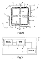
Figure 3 is a simplified block diagram of a resonant accelerometer incorporating the microelectromechanical detection structure, and an electronic apparatus provided with said resonant accelerometer; -
Figure 4 shows a schematic top plan view of a microelectromechanical detection structure, in accordance with a second embodiment of the present invention; -
Figures 5 and 6 are SEM (scanning electron microscopy) images of the microelectromechanical detection structure, respectively, ofFigures 1 and4 ; and -
Figures 7a and7b show simplified top plan views of further variants of the microelectromechanical detection structure. - As will be clarified hereinafter, one aspect of the present invention envisages the use of a single inertial mass for the detection of at least two independent components of acceleration in a plane, in particular coinciding with a plane of main extension of said inertial mass. Appropriately coupled to said single inertial mass are resonant elements for detecting the aforesaid components of acceleration according to the principle of the variation of the resonance frequency (see in this regard the foregoing description).
- In detail,
Figure 1 shows a first embodiment of a microelectromechanical detection structure, designated as a whole by 1, of a resonant biaxial accelerometer. Themicroelectromechanical detection structure 1 is produced in an integrated way, with the surface-micromachining semiconductor techniques, in particular starting from a body made of semiconductor material (such as silicon). - The
microelectromechanical detection structure 1 comprises a singleinertial mass 2, which has, for example, a generically square shape in a plane xy, corresponding to a principal plane of extension of its own, defined by a first axis x and by a second axis y, which correspond moreover to the directions of detection of the resonant biaxial accelerometer (as will be clarified hereinafter). Theinertial mass 2 has a negligible dimension in the direction orthogonal to said plane xy, along a third axis z, which defines, with the aforesaid first and second axes x, y, a set of three orthogonal axes. - In particular, the
inertial mass 2 has, in said first embodiment, four portions ofmass 2a- 2d, which have, for example, a substantially square shape in the plane xy and define an external boundary of the mass in said plane xy, and acentral portion 2e, which radiuses the portions ofmass 2a-2d at the centre and has also, for example, a substantially square shape in plan view. Theinertial mass 2 moreover has a centroidal axis (defined as the axis passing through its centre of gravity G, in this case coinciding with the geometrical centre of thecentral portion 2e), which moreover represents an axis of symmetry for themicroelectromechanical detection structure 1 and is directed orthogonal to the plane xy. - The portions of
mass 2a-2d define, in adjacent pairs,respective windows 4, numbering four in all, which extend starting from thecentral portion 2e and open towards the outside of theinertial mass 2. In particular,windows 4 of a first pair extend from opposite sides of thecentral portion 2e along the second axis y, whereas theremaining windows 4 extend along the first axis x, and are also set on opposite sides of thecentral portion 2e. In general, the structure of theinertial mass 2 is symmetrical with respect to axes parallel to the axes x and y and passing through the geometrical centre of thecentral portion 2e (centre of gravity G). - The
inertial mass 2 is anchored to a substrate (not illustrated, for example a substrate made of semiconductor material, such as silicon) so as to be suspended above said substrate, with the plane xy substantially parallel to a top surface of said substrate. - In particular, the
inertial mass 2 is elastically coupled tofirst anchorages 6, numbering four in all in the first embodiment illustrated, set externally to saidinertial mass 2, and aligned in pairs to thewindows 4 in the direction of the prolongation of saidwindows 4, along the first axis x or the second axis y. Thefirst anchorages 6 are for example constituted by pillars that extend as far as, and are mechanically connected to, the substrate. - In particular, the
inertial mass 2 is connected to the aforesaidfirst anchorages 6 by means of respective elastic elements 8 (which are also four in number in the embodiment illustrated), as a whole configured so as to maintain theinertial mass 2 suspended above the substrate and enable at least one first linear movement of translation and one second linear movement of translation thereof (with respect to said substrate), respectively along the first axis x and the second axis y, and as to prevent movements thereof out of said plane xy. - Each
elastic element 8 comprises: afirst portion 8a, constituted by a rectilinear linear spring (the so-called "single beam"), which extends along the first axis x or second axis y starting from an external lateral surface of thecentral portion 2e of the inertial mass 2 (centrally with respect thereto), within arespective window 4; asecond portion 8b, connected to thefirst portion 8a, and constituted by a folded spring (the so-called "folded beam"), having extension in a direction transverse to thefirst portion 8a, in particular along the second axis y or first axis x (thesecond portion 8b is hence constituted by a plurality of rectilinear springs, parallel to one another, which have main extension in the aforesaid transverse direction and are radiused to one another at the corresponding ends); and athird portion 8c, connected to thesecond portion 8b and constituted once again by a rectilinear spring, having extension along the first axis x or second axis y, as prolongation of thefirst portion 8a, with length much smaller than the corresponding length of saidfirst portion 8a, until it reaches a respectivefirst anchorage 6, joining to an external lateral surface thereof facing the corresponding lateral surface of thecentral portion 2e. - In particular, the
elastic elements 8 are very thin (the corresponding constituent portions have, that is, a length in the direction of extension much greater than the corresponding width). - The
microelectromechanical detection structure 1 further comprises a resonant part, formed by fourresonant elements 10a-10d, each of which is constituted by a thin resonant beam. - In the embodiment illustrated, the
resonant elements 10a-10d are set externally to theinertial mass 2, with respect to the plane xy, and extend parallel in pairs along the first axis x or the second axis y, moreover parallel to thesecond portion 8b of an associatedelastic element 8, externally thereto. - In particular, each
resonant element 10a-10d is rigidly constrained to the substrate at a first end thereof, by means of a respective second anchorage 12 (once again constituted, for example, by a pillar that extends as far as, and is connected to, the substrate), and extends starting from saidsecond anchorage 12 until it joins, with a second end of its own, a respectiveelastic element 8, in particular thethird portion 8c of saidelastic element 8, in close proximity of the respectivefirst anchorage 6 of saidelastic element 8. The point of connection of theresonant element 10a-10d to the respectiveelastic element 8 is designated by c. Eachresonant element 10a-10d hence forms with the part of thethird portion 8c of the respectiveelastic element 8, comprised between the point of connection c and the correspondingfirst anchorage 6, an L-shaped resonant structure. - Each
resonant element 10a-10d is hence mechanically coupled to theinertial mass 2 through a respectiveelastic element 8. Advantageously, said configuration enables high values of detection sensitivity to be obtained with aninertial mass 2 of contained dimensions in so far as the intermediate presence of theelastic elements 8 prevents the stiffness of theresonant elements 10a-10d from hindering directly theinertial mass 2 and hence reducing the excursion of the movements thereof upon detection of the external accelerations. - It has moreover been verified that the position of the point of connection c in the close proximity of the
first anchorages 6 is a factor that determines the electrical characteristics of the resonant detection structure (in terms of amplification of the axial force in response to an external acceleration, and hence of the detection sensitivity). In particular, it has been verified, by means of simulations and experimental tests, that it is advantageous, in order to improve the detection sensitivity (defined as the variation of frequency produced by an acceleration of 1g, g being the acceleration of gravity), to position the point of connection c very close to the position of thefirst anchorages 6 of theelastic elements 8. For example, if we designate by L the length of saidelastic elements 8, considered as a whole, along the first axis x or second axis y (from thecentral portion 2e of theinertial mass 2 up to the respective first anchorage 6), it is advantageous to position the point of connection c at a distance from the correspondingfirst anchorage 6 comprised between 0.01·L and 0.02·L, for example, at approximately one sixtieth of the length L starting from the correspondingfirst anchorage 6. - The configuration described of the
resonant elements 10a-10d moreover advantageously enables increase in the interval of linear behaviour in frequency of themicroelectromechanical detection structure 1. In particular, it may be shown that the presence of the part of thethird portion 8c of theelastic elements 8, comprised between the point of connection c and the correspondingfirst anchorage 6, of small dimensions, causes the linear behaviour of eachresonant element 10a-10d not to depart substantially from that of standard resonators constrained at both ends (the so-called "double-clamped" resonators), while the non-linear behaviour is instead considerably improved. For example, the so-called "hard spring" effect exhibited by double-clamped resonators, in the presence of oscillations of amplitude comparable with the width of said resonators, is considerably attenuated in the proposed structure, thanks to the change in the boundary conditions defined by coupling of one of the ends of theresonant elements 10a-10d to the respectiveelastic element 8. - The
microelectromechanical detection structure 1 further comprises, for eachresonant element 10a-10d, a pair ofelectrodes resonant element 10a- 10d, on opposite sides of saidresonant element 10a- 10d with respect to the first axis x or second axis y. Afirst electrode 13 is used to send the associatedresonant element 10a-10d into a resonance condition by applying an appropriate difference of electrical potential, whilst asecond electrode 14 is used as detection electrode, for detecting, by means of a variation of the capacitive coupling with theresonant element 10a-10d, variations of the corresponding resonance frequency (according to a detection scheme known as "parallel plate"). As shown inFigure 1 , theelectrodes second anchorage 12 and thethird portion 8c of the facingelastic element 8. In a way not illustrated, appropriate electrical-connection paths are envisaged for the electrical connection of theaforesaid electrodes microelectromechanical detection structure 1. Said electronic circuit is configured so as to supply the electrical signals of actuation to themicroelectromechanical detection structure 1, and receive and process the electrical detection signals supplied by saidmicroelectromechanical detection structure 1. - In a way not illustrated herein, there may be moreover provided appropriate stopper elements for limiting the excursion of the movement of the
inertial mass 2 in the plane xy. Said stoppers are conveniently anchored to the substrate and are able to stop the movement of theinertial mass 2. In any case, it has been shown that the stresses to which theelastic elements 8 are subjected, in particular at the correspondingfirst anchorages 6, can amply fall within the limits of resistance of the material of which they are made (for example polysilicon). - The principle of operation of the
microelectromechanical detection structure 1 will now be described with reference also toFigures 2a-2c , which illustrate possible deformations thereof in response to different external stresses, and in particular in response to: a first, linear, acceleration acting along the first axis x (Figure 2a ); a second, linear, acceleration acting along the second axis y (Figure 2b ); and a third, angular, acceleration acting about the centroidal axis, or, in an equivalent way, about the third axis z. As will be highlighted in detail, the arrangement of theelastic elements 8 enables in fact three movements of theinertial mass 2 in the plane xy (a first translation and a second translation, respectively along the first axis x and the second axis y, and moreover a rotation about the third axis z); the effects of said movements on theresonant elements 10a-10d can be decoupled in such a way as to enable detection of the corresponding components of acceleration individually and without mutual interference. - In the absence of external acceleration, the four
resonant elements 10a-10d have the same nominal frequency of resonance f0, as a result of the interaction with the correspondingfirst electrodes 13 and the associated electronic circuit. - When the
inertial mass 2 is subjected to a first acceleration ax along the first axis x (in the direction of the arrow inFigure 2a ), theinertial mass 2 translates as a whole along said first axis x, as a result of the bending of the second (folded)portion 8b of a first pair of theelastic elements 8, and moreover of the bending of the first (linear)portion 8a of the remaining elastic elements 8 (in general, there occurs the bending of the springs with extension transverse to the direction of displacement, in this case with extension along the second axis y, whilst the springs with extension along the first axis x do not undergo an appreciable axial deformation). It should be noted that inFigure 2a (as in the subsequentFigures 2b and2c ) the starting position of theinertial mass 2 is indicated with a dashed line, whilst the position resulting from the displacement due to the external acceleration is indicated with a solid line. - The movement of translation of the
inertial mass 2 along the first axis x consequently causes, evidently, an compressive stress - N1 on a firstresonant element 10a of the pair of resonant elements arranged along the first axis x, and a tensile stress N1, having the same intensity, on the secondresonant element 10c of said pair; in particular, the movement of theinertial mass 2 is transmitted to theresonant elements elastic elements 8, at the point of connection c, the position of which is substantially constrained. - Consequently, the resonance frequency of the first
resonant element 10a, designated by f1, undergoes a decrease in its value, whilst the resonance frequency of the secondresonant element 10c of the pair, designated by f2, undergoes a corresponding increase in its value. With an appropriate combination of the electrical signals at output from the tworesonant elements 
- Said difference is hence directly proportional to the compressive/tensile stress N1 acting on the
resonant elements - It is emphasized that the presence of the two resonant elements, in this case the
resonant elements - the sensitivity in detection of the external accelerations is twice as much when the difference between the frequency of the two resonant elements is measured instead of the variation of frequency of a single resonant element;
- the linearity of the system is improved, i.e., the response of the accelerometer can be linearized in a wider range of accelerations; and
- the geometry described is less sensitive to the spurious effects of the thermal load, given that, when the difference between the frequencies is considered, a non-elastic effect that causes a pre-stress in the resonant elements vanished.
- Advantageously, the
resonant elements - In an altogether similar way, and as illustrated in
Figure 2b , a second acceleration ay acting along the second axis y determines an overall displacement of theinertial mass 2 along the second axis y (in the direction indicated by the arrow inFigure 2b ). - The movement of translation of the
inertial mass 2 along the second axis y causes in this case a compressive stress - N2 (with N2 that can be equal to N1, in the case of a perfectly symmetrical structure) on a firstresonant element 10d of the pair of resonant elements arranged along the second axis y, and a tensile stress N2, of the same intensity, on the secondresonant element 10b of the pair. In a way altogether similar to what has been discussed previously, the difference between the resonance frequencies (f4-f3) of saidresonant elements microelectromechanical detection structure 1. - Also in this case, the
resonant elements - The
microelectromechanical detection structure 1 is moreover sensitive to a third, angular, external acceleration aθ acting about the third axis z, as illustrated inFigure 2c . - In this case, the
inertial mass 2 is set in rotation about its centroidal axis, causing axial stresses of the same value and sign, Nθ, in all fourresonant elements 10a-10d. In this case, by appropriately adding the values of resonance frequency f1-f4 of theresonant elements 10a-10d, a measurement of the stress acting on saidresonant elements 10a-10d, and hence of the third external acceleration aθ, is obtained as follows:
- It is hence evident that the
microelectromechanical detection structure 1 is configured in such a way as to decouple the effects of the external accelerations on theresonant elements 10a-10d, and in particular in such a way that it is possible, by means of appropriate combinations of the electrical quantities supplied by the variousresonant elements 10a-10d, to determine independently the value of said external accelerations. - For this purpose, as shown in
Figure 3 , themicroelectromechanical detection structure 1 is conveniently coupled to an appropriateelectronic reading circuit 15, configured in such a way as to carry out the aforesaid processing operations and combinations of the values of frequency f1-f4 in order to determine the values of the linear external accelerations, ax and ay, and angular acceleration aθ. Conveniently, theelectronic reading circuit 15 comprises three measurement channels decoupled from one another, for the measurement one of the first linear acceleration ax, one of the second external linear acceleration ay, and one of the external angular acceleration aθ). Themicroelectromechanical detection structure 1 and the associatedelectronic reading circuit 15 form together a resonant biaxial accelerometer 16 (moreover able to detect an angular acceleration, as illustrated previously). Theelectronic reading circuit 15 is conveniently provided in an integrated form as ASIC (application-specific integrated circuit), in a die, which can be advantageously housed in the same package that houses also the die in which themicroelectromechanical detection structure 1 is provided. - As shown schematically in said
Figure 3 , anelectronic apparatus 18, provided with said resonantbiaxial accelerometer 16, for example a portable apparatus, such as a laptop, a palm-top, or a photographic camera or a video-camera, further comprises a control unit 19 (for example, a microprocessor control unit), electrically connected to theelectronic reading circuit 15 so as to receive the measurements of acceleration for carrying out operations of control for management of saidelectronic apparatus 18. - There now follows a description, with reference to
Figure 4 , of a second embodiment of the microelectromechanical detection structure, designated herein by 1', which differs from the one illustrated previously by a different configuration of its constitutive elements. Operation of the microelectromechanical detection structure 1' does not differ, instead, from what has been illustrated previously, and, for said reason, will not be described again in what follows. - In particular, said second embodiment is distinguished by the fact that the
resonant elements 10a-10d are set internally with respect to the encumbrance of the inertial mass, designated here by 2', in the plane xy. - In detail, the inertial mass 2' comprises in this case a
frame 20, for example having a substantially square perimeter in the plane xy, and defining inside aninternal opening 22. The inertial mass 2' also comprises in this case four portions of mass, designated here by 2a'-2d', which are arranged inside theframe 20 in theinternal opening 22 and are connected to respective internal corners of saidframe 20. The portions ofmass 2a'-2d' have, for example, a substantially rectangular shape in the plane xy and are arranged parallel in pairs and symmetrically with respect to the centre of gravity G. - The inertial mass 2' is here fixed to the substrate (once again not illustrated) by means of a single
first anchorage 6, set centrally in theinternal opening 22, and traversed centrally by the centroidal axis (in a position corresponding to the centre of gravity G). - The
elastic elements 8, which are four in number, hence also extend in theinternal opening 22, within theframe 20, starting from respective external lateral surfaces of thefirst anchorage 6 as far as a facing lateral internal surface of saidframe 20. Thesecond portion 8b of eachelastic element 8 is in particular set between the internal lateral surface of saidframe 20 and a lateral surface of respective portions ofmass 2a'-2d' of the inertial mass 2', facing it. In this case, thefirst portion 8a of eachelastic element 8 has a length much smaller than that of thethird portion 8c, given the central position of the singlefirst anchorage 6 and the arrangement of thesecond portion 8b of saidelastic elements 8. - In addition, the
resonant elements 10a-10d are arranged in theinternal opening 22, inside theframe 20, facing therespective electrodes internal opening 22. In particular, theresonant elements 10a-10d, and the associatedelectrodes mass 2a'-2d' with respect to theframe 20, in the proximity of central axes of symmetry of the inertial mass 2' (parallel to the first axis x and to the second axis y). - Once again, the
resonant elements 10a-10d extend from a respective second anchorage 12 (thesecond anchorages 12 being four in number and being arranged in the internal opening 22), until they connect up to a respectiveelastic element 8, in particular to thethird portion 8c of saidelastic element 8. The point of connection c in which eachresonant element 10a-10d is connected to the respectiveelastic element 8 is in this case in close proximity of the singlefirst anchorage 6, set centrally with respect to the structure. - Said second embodiment has the advantage of presenting a compact structure, all enclosed inside the
frame 20 of the inertial mass 2'. In addition, the presence of a singlefirst anchorage 6 for said inertial mass 2', set in a position corresponding to the centre of gravity G of the structure, is advantageous for the reduction of the thermomechanical stresses possibly acting on the structure (for example, due to deformations of the package of the resonant biaxial accelerometer 16). Once again in order to reduce the thermomechanical stress, it is advantageous to arrange thesecond anchorages 12 of theresonant elements 10a-10d inside the inertial mass 2', which are also close to the centre of gravity G of the structure. -
Figures 5 and 6 are top plan views of themicroelectromechanical detection structures 1, 1' described previously, respectively according to the first embodiment and the second embodiment, obtained by means of SEM. There may be noted the presence of holes made throughout the thickness of theinertial mass 2, 2', in order to enable release thereof with respect to the substrate by chemical etching of underlying regions of material, and moreover the presence of appropriate paths for electrical connection to the elements of the structure. In addition, in said images, designated by 30 is the substrate of themicroelectromechanical detection structures 1, 1', made for example of silicon, and designated by 31 are the stopper elements arranged at the corners of theinertial mass 2, 2'. - The
microelectromechanical detection structure 1, 1' can be obtaining with surface-micromachining processes, for example using the so-called ThELMA (thick epipoly layer for microactuators and accelerometers) process. - The ThELMA process enables fabrication of suspended structures of relatively large thicknesses (for example of the order of 10-15 µm), anchored to the substrate through compliant parts (springs) and consequently capable of displacing at least in a plane parallel to the underlying silicon substrate (the plane xy referred to above). The process consists of different production steps:
- thermal oxidation of the substrate;
- deposition and patterning of horizontal electrical interconnections;
- deposition and patterning of a sacrificial layer;
- epitaxial growth of a structural layer (for example, made of polysilicon and with a thickness of 15 µm);
- patterning of the structural layer by means of trench etching; and
- removal of the sacrificial oxide and deposition of contact metallizations.
- From what has been described and illustrated previously, the advantages that the present invention affords are evident.
- In particular, the
microelectromechanical detection structure 1, 1', combined with an appropriateelectronic reading circuit 15, provides biaxialresonant accelerometers 16 of a very small size, smaller in particular than that of capacitive accelerometers obtained with the same technology. The reduction in size is obtained by using a singleinertial mass 2, 2' for detection of two components of acceleration in the plane xy, and possibly, albeit with lower sensitivity, of a further angular acceleration, and moreover by means of an appropriate arrangement of theresonant elements 10a-10d with respect to saidinertial mass 2, 2'. - Given the same overall dimensions, it is possible to obtain high values of sensitivity as compared to traditional structures. In the first embodiment, the structure proposed enables, for example, with dimensions of approximately 550 µm x 550 µm, a sensitivity higher than 200 Hz/g to be obtained. The sensitivity for the angular acceleration is, instead, lower than the sensitivity for the linear accelerations in the plane xy, for example, in the region of 0.05 Hz/(rad/s2).
- The structure proposed enables reduction of the effects of the spurious axial forces on the resonant beams, and moreover the differential measurement of frequency increases the range of linearity of the accelerometer. In particular, the presence of two resonant elements subjected to axial action of opposite sign for a given external linear acceleration enables measurement of acceleration even in the presence of a state of internal stress generated, for example, by a thermal variation.
- Finally, it is clear that modifications and variations may be made to what has been described and illustrated so far, without thereby departing from the scope of the present invention as defined in the annexed claims.
- In particular, it is evident that the geometrical shape of the
microelectromechanical detection structure 1, 1', or of parts thereof, could differ from the one described previously. In addition, themicroelectromechanical detection structure 1, 1' could comprise a singleresonant element 10a-10d for each axis of detection x, y. -
Figures 7a and7b show further variants of themicroelectromechanical detection structure 1, in which theresonant elements 10a-10d and the correspondingsecond anchorages 12, as also thefirst anchorages 6 of theinertial mass 2, are arranged externally with respect to theinertial mass 2, in the plane xy. In this case, astopper element 31 is set centrally with respect to theinertial mass 2, within an opening made through saidinertial mass 2, which otherwise is constituted by a single body of a generically square shape in plan view. - In said variants, the
elastic elements 8, and in particular the correspondingsecond portions 8b, of a folded type, are connected toprojections 34 of the inertial mass 2 (which project with respect to the substantially square overall dimensions of saidinertial mass 2 in the plane xy). It should be noted that, in a way not illustrated, theelastic elements 8 can also in this case comprise firstrectilinear portions 8a, set between respectivesecond portions 8b andprojections 34. - In particular, in the variant of
Figure 7a , theprojections 34, which are four in number, are arranged centrally with respect to respective peripheral sides of theinertial mass 2, whilst in the variant ofFigure 7b theprojections 34 are arranged at the corners of theinertial mass 2. - The
third portions 8c, of a rectilinear type, of saidelastic elements 8 extend once again in a direction transverse to the respectiveresonant elements 10a-10d, connecting up to the respectivefirst anchorages 6 of the inertial mass 2 (which are here again four in number). Theresonant elements 10a-10d are connected to theelastic elements 8, at a point of connection c of the correspondingthird portion 8c, close to the correspondingfirst anchorage 6. Thesecond portions 8b ofelastic elements 8 associated toresonant elements 10a-10d that do not belong to said pair (i.e., are not directed along said axis) are moreover arranged parallel and adjacent to peripheral opposite sides, facing one another, of theinertial mass 2. - Operation of the
microelectromechanical detection structure 1 in the embodiments ofFigures 7a ,7b , and in particular the deformations of the constitutive elements following upon external accelerations, does not differ from what has been described previously.
Claims (12)
- A microelectromechanical detection structure (1; 1') for a MEMS resonant biaxial accelerometer (16), comprising:- an inertial mass (2; 2'), anchored to a substrate (30) by means of elastic elements (8) so as to be suspended above said substrate (30), said elastic elements (8) configured to enable inertial movements of detection of said inertial mass (2; 2') along a first detection axis (x) and a second detection axis (y) belonging to a plane (xy) of main extension of said inertial mass (2; 2'), responsive to respective linear external accelerations (ax, ay); and- at least one first resonant element (10a) and one second resonant element (10b), having a respective longitudinal extension, respectively along said first detection axis (x) and said second detection axis (y), and mechanically coupled to said inertial mass (2; 2') through a respective one of said elastic elements (8), so as to undergo a respective axial stress (N1, N2) when said inertial mass moves respectively along said first detection axis (x) and along said second detection axis (y);wherein each of said elastic elements (8) extends starting from a first anchorage (6) of said inertial mass (2; 2') to said substrate (30), as far as said inertial mass (2; 2'); and wherein each of said first (10a) and second (10b) resonant element is anchored to said substrate (30) at a first end thereof by means of a respective second anchorage (12), and is moreover mechanically connected to the respective one of said elastic elements (8) at a second end thereof, to a connection point (c) of the respective one of said elastic elements (8); wherein said connection point (c) is positioned along said respective one of said elastic elements (8), at a distance from the corresponding first anchorage (6) comprised between 1/100 and 2/100 of a length (L) of said respective one of said elastic elements (8) in a direction transverse to said longitudinal extension of the associated first (10a) or second (10b) resonant element; and wherein each of said elastic elements (8) comprises: a rectilinear portion (8c), extending from the first anchorage (6) in a direction transverse to said longitudinal extension of the associated first (10a) or second (10b) resonant element, and a folded portion (8b), which is mechanically coupled, and extends in a direction transverse to said rectilinear portion (8c); said rectilinear portion (8c) being coupled to the associated first (10a) or second (10b) resonant element at said connection point (c).
- The structure according to any one of the preceding claims, wherein said rectilinear portion (8c) is configured to bend to enable axial stress (N1, N2) thereof when said inertial mass moves along said first (x) or second (y) detection axis, respectively, i.e., in a direction parallel to the longitudinal extension of the associated first (10a) or second (10b) resonant element; and said folded portion (8b) is configured to undergo deformation when said inertial mass moves along said second (y) or first (x) detection axis, respectively, i.e., in a direction transverse to the longitudinal extension of the associated first (10a) or second (10b) resonant element.
- The structure according to claim 1 or 2, wherein said folded portion (8b) comprises a plurality of rectilinear segments, parallel to one another and joined at respective ends; and wherein said rectilinear portion (8c) has a first end connected to the corresponding first anchorage (6) and a second end connected to a terminal rectilinear segment of said folded portion (8b); each of said elastic elements (8) comprising a further rectilinear portion (8a) having a first end connected to said inertial mass (2; 2') and a second end connected to an initial rectilinear segment of said folded portion (8b).
- The structure according to any one of the preceding claims, further comprising a third (10c) and a fourth (10d) resonant elements, having a longitudinal extension, respectively, along said first (x) and second (y) detection axis, in a direction parallel, respectively, to said first (10a) and second (10b) resonant element, and mechanically coupled to said inertial mass (2; 2') through respective ones of said elastic elements (8), in such a way as to undergo a respective axial stress (N1, N2) of the same intensity and opposite sign with respect to the axial stress of said first (10a) and second (10b) resonant element, respectively, when said inertial mass moves along said first (x) and second (y) detection axis, respectively.
- The structure according to any one of the preceding claims, wherein said first (10a) and second (10b) resonant elements are arranged externally to said inertial mass (2) with respect to said plane (xy); and wherein said inertial mass (2) has a central portion (2e) and side portions (2a-2d), which are connected by said central portion (2e) and define between them windows (4), which open towards the outside of said inertial mass (2); and wherein said elastic elements (8) extend starting from said central portion (2e), in part through said windows (4) so as to reach respective first anchorages (6) of said inertial mass (2) to said substrate (30), which are set externally to said inertial mass (2) with respect to said plane (xy).
- The structure according to any one of the preceding claims, wherein said first (10a) and second (10b) resonant elements are arranged externally to said inertial mass (2) with respect to said plane (xy), and said inertial mass (2) has projections (34) that extend in said plane (xy) starting from peripheral sides of said inertial mass; said elastic elements (8) extending starting from respective projections (34) until they reach respective first anchorages (6) of said inertial mass (2) to said substrate (30), said first anchorages (6) being arranged externally to said inertial mass (2) with respect to said plane (xy) ; and wherein said folded portion (8b) extends adjacent to a first one of said peripheral sides of said inertial mass (2), and said associated first (10a) or second (10b) resonant element extend adjacent to a second one of said peripheral sides, parallel to and facing said second peripheral side.
- The structure according to any one of claims 1-4, wherein said inertial mass (2') comprises a frame (20) defining inside it an internal opening (22), and said elastic elements (8) extend entirely in said internal opening (22) starting from said frame (20) until they reach a single first anchorage (6) of said inertial mass (2') to said substrate (30), said single first anchorage (6) being arranged centrally with respect to said internal opening (22); and wherein said first (10a) and second (10b) resonant elements are set internally to said inertial mass (2) with respect to said plane (xy), in said internal opening (22).
- The structure according to any one of the preceding claims, wherein said elastic elements (8) are configured to enable a further inertial movement of detection of said inertial mass (2; 2'), i.e., a rotation about an axis (z) orthogonal to said plane (xy), in response to an external angular acceleration (aθ); and wherein said first (10a) and second (10b) resonant elements are mechanically coupled to said inertial mass (2; 2') through a respective one of said elastic elements (8) in such a way as to undergo a same axial stress (Nθ), when said inertial mass moves according to said further inertial movement of detection.
- The structure according to any one of the preceding claims, further comprising first electrodes (13), electrically coupled to said first (10a) and second (10b) resonant elements to enable generation of a resonance state thereof; and second electrodes (14), electrically coupled to said first (10a) and second (10b) resonant elements to enable detection of a respective variation of a resonance frequency (f1, f2), as a function of said respective axial stress (N1, N2).
- A resonant biaxial accelerometer (16), comprising a microelectromechanical detection structure (1; 1') according to any one of the preceding claims, and configured to detect a first (ax) and a second (ay) linear external acceleration components, directed, respectively, along said first (x) and second (y) detection axes.
- The accelerometer according to claim 10, further comprising a reading circuit (15), electrically coupled to said microelectromechanical detection structure (1; 1').
- An electronic apparatus (18), comprising a resonant biaxial accelerometer (16) according to claim 10 or 11, and a control unit (19), electrically connected to said reading circuit (15).
Applications Claiming Priority (2)
| Application Number | Priority Date | Filing Date | Title |
|---|---|---|---|
| ITTO2010A000944A IT1405796B1 (en) | 2010-11-26 | 2010-11-26 | BIONIAL ACCELEROMETER STRUCTURE RESONANT OF MICROELETTROMECHANICAL TYPE |
| PCT/IB2011/055309 WO2012070021A1 (en) | 2010-11-26 | 2011-11-25 | Resonant biaxial accelerometer structure of the microelectromechanical type |
Publications (2)
| Publication Number | Publication Date |
|---|---|
| EP2643702A1 EP2643702A1 (en) | 2013-10-02 |
| EP2643702B1 true EP2643702B1 (en) | 2015-08-05 |
Family
ID=43743107
Family Applications (1)
| Application Number | Title | Priority Date | Filing Date |
|---|---|---|---|
| EP11799844.3A Active EP2643702B1 (en) | 2010-11-26 | 2011-11-25 | Resonant biaxial accelerometer structure of the microelectromechanical type |
Country Status (5)
| Country | Link |
|---|---|
| US (1) | US8671756B2 (en) |
| EP (1) | EP2643702B1 (en) |
| CN (1) | CN103250057B (en) |
| IT (1) | IT1405796B1 (en) |
| WO (1) | WO2012070021A1 (en) |
Families Citing this family (35)
| Publication number | Priority date | Publication date | Assignee | Title |
|---|---|---|---|---|
| US8022554B2 (en) | 2006-06-15 | 2011-09-20 | Sitime Corporation | Stacked die package for MEMS resonator system |
| IT1395419B1 (en) * | 2009-09-07 | 2012-09-14 | Milano Politecnico | ACCONEROMETER RESONATING MEMS WITH IMPROVED ELECTRIC CHARACTERISTICS |
| GB201009062D0 (en) * | 2010-05-28 | 2010-07-14 | Cambridge Entpr Ltd | MEMS inertial sensor and method of inertial sensing |
| US9695036B1 (en) * | 2012-02-02 | 2017-07-04 | Sitime Corporation | Temperature insensitive resonant elements and oscillators and methods of designing and manufacturing same |
| US8916407B1 (en) | 2012-03-29 | 2014-12-23 | Sitime Corporation | MEMS device and method of manufacturing same |
| ITTO20120691A1 (en) * | 2012-08-01 | 2014-02-02 | Milano Politecnico | IMPACT SENSOR WITH BISTABLE MECHANISM AND METHOD FOR DETECTING IMPACTS |
| GB2505875A (en) * | 2012-09-04 | 2014-03-19 | Cambridge Entpr Ltd | Dual and triple axis inertial sensors and methods of inertial sensing |
| JP6020392B2 (en) | 2013-09-03 | 2016-11-02 | 株式会社デンソー | Acceleration sensor |
| CN103454449A (en) * | 2013-09-15 | 2013-12-18 | 滕金燕 | Three-axis micro-mechanical accelerometer |
| US9705470B1 (en) | 2014-02-09 | 2017-07-11 | Sitime Corporation | Temperature-engineered MEMS resonator |
| US9712128B2 (en) | 2014-02-09 | 2017-07-18 | Sitime Corporation | Microelectromechanical resonator |
| US9581614B2 (en) | 2014-06-02 | 2017-02-28 | Meggit (Orange County), Inc. | High-output MEMS accelerometer |
| US9625486B2 (en) | 2014-07-17 | 2017-04-18 | Meggitt (Orange County), Inc. | MEMS accelerometer |
| US9689888B2 (en) * | 2014-11-14 | 2017-06-27 | Honeywell International Inc. | In-plane vibrating beam accelerometer |
| US10823754B2 (en) | 2014-11-14 | 2020-11-03 | Honeywell International Inc. | Accelerometer with strain compensation |
| CN104865406A (en) * | 2015-03-27 | 2015-08-26 | 东南大学 | Lever-amplification-principle-based dual-shaft full-decoupling silicone micro-resonator type accelerometer |
| EP3136052B1 (en) * | 2015-08-31 | 2021-03-24 | Commissariat à l'Énergie Atomique et aux Énergies Alternatives | Piezoresistive detection resonant device in particular with large vibration amplitude |
| US10545167B2 (en) | 2015-10-20 | 2020-01-28 | Analog Devices, Inc. | Multiple-axis resonant accelerometers |
| ITUA20162173A1 (en) | 2016-03-31 | 2017-10-01 | St Microelectronics Srl | ACCELEROMETRIC MEMS SENSOR HAVING HIGH ACCURACY AND REDUCED SENSITIVITY TOWARDS TEMPERATURE AND AGING |
| US10676349B1 (en) | 2016-08-12 | 2020-06-09 | Sitime Corporation | MEMS resonator |
| CN106771358A (en) * | 2016-11-30 | 2017-05-31 | 西安交通大学 | A kind of full quartz resonance accelerometer of miniature differential formula |
| CN106597011B (en) * | 2016-12-23 | 2018-11-23 | 中北大学 | Biaxial MEMS resonant mode acceleration sensor structure |
| CN108225544B (en) * | 2017-11-27 | 2020-02-18 | 东南大学 | Double-layer multiplexing type triangular folded beam mass block resonance system and trace detection method thereof |
| CN108092638B (en) * | 2017-11-27 | 2021-03-19 | 东南大学 | Resonance system, detection method and manufacturing process of mass block of triangular folding beam |
| RU180986U1 (en) * | 2018-03-05 | 2018-07-03 | Общество с ограниченной ответственностью "Лаборатория Микроприборов" (ООО "ЛМП) | Vibration linear acceleration sensor |
| US10895457B2 (en) | 2018-03-08 | 2021-01-19 | Analog Devices, Inc. | Differential z-axis resonant accelerometry |
| US11275099B1 (en) * | 2018-07-20 | 2022-03-15 | Hrl Laboratories, Llc | Navigational grade resonant MicroElectroMechanical Systems (mems) accelerometer and method of operation |
| RU190397U1 (en) * | 2018-08-13 | 2019-07-01 | Акционерное общество "ГИРООПТИКА" (АО "ГИРООПТИКА") | MICROMECHANICAL AXIAL ACCELEROMETER |
| US10816569B2 (en) | 2018-09-07 | 2020-10-27 | Analog Devices, Inc. | Z axis accelerometer using variable vertical gaps |
| US11255873B2 (en) | 2018-09-12 | 2022-02-22 | Analog Devices, Inc. | Increased sensitivity z-axis accelerometer |
| JP6870761B2 (en) | 2019-05-15 | 2021-05-12 | 株式会社村田製作所 | Robust Z-axis accelerometer |
| US10823569B1 (en) | 2019-08-22 | 2020-11-03 | Nxp Usa, Inc. | Multiple axis sensing device based on frequency modulation and method of operation |
| US11377346B2 (en) | 2019-09-11 | 2022-07-05 | Murata Manufacturing Co., Ltd. | Low-noise multi axis MEMS accelerometer |
| EP3792637B1 (en) | 2019-09-11 | 2023-05-03 | Murata Manufacturing Co., Ltd. | Low-noise multi-axis mems accelerometer |
| IT202100023795A1 (en) | 2021-09-15 | 2023-03-15 | St Microelectronics Srl | Z-AXIS RESONANT ACCELEROMETER WITH DETECTION STRUCTURE HAVING IMPROVED PERFORMANCE |
Family Cites Families (20)
| Publication number | Priority date | Publication date | Assignee | Title |
|---|---|---|---|---|
| US4851080A (en) * | 1987-06-29 | 1989-07-25 | Massachusetts Institute Of Technology | Resonant accelerometer |
| FR2667157B1 (en) | 1990-09-25 | 1994-06-10 | Sextant Avionique | RESONATOR MICRO-ACCELEROMETER AND MANUFACTURING METHOD. |
| FR2720509B1 (en) | 1994-05-27 | 1996-08-23 | Sextant Avionique | Temperature compensated resonator microaccelerometer. |
| FR2723638B1 (en) | 1994-08-10 | 1996-10-18 | Sagem | FORCE-FREQUENCY TRANSDUCER WITH VIBRATING BEAMS |
| US5894090A (en) * | 1996-05-31 | 1999-04-13 | California Institute Of Technology | Silicon bulk micromachined, symmetric, degenerate vibratorygyroscope, accelerometer and sensor and method for using the same |
| US5969249A (en) | 1997-05-07 | 1999-10-19 | The Regents Of The University Of California | Resonant accelerometer with flexural lever leverage system |
| US5948982A (en) | 1998-02-23 | 1999-09-07 | Alliedsignal Inc. | Vibrating beam accelerometers and methods of forming vibrating beam accelerometers |
| DE19812773C2 (en) * | 1998-03-24 | 2002-11-14 | Conti Temic Microelectronic | Microsensor with a resonator structure |
| FR2784752B1 (en) | 1998-10-20 | 2000-11-17 | Onera (Off Nat Aerospatiale) | MONOLITHIC MINIATURE ACCELEROMETER |
| JP2001174264A (en) | 1999-12-21 | 2001-06-29 | Murata Mfg Co Ltd | Resonance element and its vibration adjusting method |
| US6662655B2 (en) | 2000-10-31 | 2003-12-16 | Honeywell International, Inc. | Net zero isolator |
| US6662658B2 (en) | 2001-01-17 | 2003-12-16 | Honeywell International, Inc. | Whiffletree accelerometer |
| FR2821434B1 (en) | 2001-02-26 | 2003-07-04 | Sagem | TWO-CELL MINIATURE ACCELEROMETER |
| KR20030097874A (en) | 2001-05-15 | 2003-12-31 | 허니웰 인터내셔널 인코포레이티드 | Accelerometer strain relief structure |
| US6651500B2 (en) | 2001-10-03 | 2003-11-25 | Litton Systems, Inc. | Micromachined silicon tuned counterbalanced accelerometer-gyro with quadrature nulling |
| FR2848298B1 (en) * | 2002-12-10 | 2005-03-11 | Thales Sa | ACCELEROMETER WITH VIBRATING BEAM |
| FR2862761B1 (en) | 2003-11-25 | 2006-02-03 | Thales Sa | DIFFERENTIAL ACCELEROMETER MICRO-FACTORY MULTIAXES |
| FR2906038B1 (en) | 2006-09-19 | 2008-11-28 | Commissariat Energie Atomique | RESONANT BEAM ACCELEROMETER WITH ARTICULATING ROTATING LEVER ARM |
| WO2009048621A1 (en) * | 2007-10-11 | 2009-04-16 | Georgia Tech Research Corporation | Bulk acoustic wave accelerometers |
| IT1395419B1 (en) | 2009-09-07 | 2012-09-14 | Milano Politecnico | ACCONEROMETER RESONATING MEMS WITH IMPROVED ELECTRIC CHARACTERISTICS |
-
2010
- 2010-11-26 IT ITTO2010A000944A patent/IT1405796B1/en active
-
2011
- 2011-11-22 US US13/303,038 patent/US8671756B2/en active Active
- 2011-11-25 EP EP11799844.3A patent/EP2643702B1/en active Active
- 2011-11-25 CN CN201180058118.4A patent/CN103250057B/en active Active
- 2011-11-25 WO PCT/IB2011/055309 patent/WO2012070021A1/en active Application Filing
Also Published As
| Publication number | Publication date |
|---|---|
| WO2012070021A1 (en) | 2012-05-31 |
| IT1405796B1 (en) | 2014-01-24 |
| CN103250057A (en) | 2013-08-14 |
| EP2643702A1 (en) | 2013-10-02 |
| US20120132003A1 (en) | 2012-05-31 |
| ITTO20100944A1 (en) | 2012-05-27 |
| US8671756B2 (en) | 2014-03-18 |
| CN103250057B (en) | 2016-04-27 |
Similar Documents
| Publication | Publication Date | Title |
|---|---|---|
| EP2643702B1 (en) | Resonant biaxial accelerometer structure of the microelectromechanical type | |
| US8516889B2 (en) | MEMS resonant accelerometer having improved electrical characteristics | |
| EP2893362B1 (en) | Dual and triple axis inertial sensors and methods of inertial sensing | |
| US9989364B2 (en) | Acceleration and angular velocity resonant detection integrated structure, and related MEMS sensor device | |
| US6634231B2 (en) | Accelerometer strain isolator | |
| US6662658B2 (en) | Whiffletree accelerometer | |
| US8616059B2 (en) | Force sensor with reduced noise | |
| EP2577324B1 (en) | Mems inertial sensor and method of inertial sensing | |
| US8297121B2 (en) | Micro-machined accelerometer | |
| CA2733940A1 (en) | Solid-state inertial sensor on chip | |
| Li et al. | A micro-machined differential resonance accelerometer based on silicon on quartz method | |
| Tabata et al. | Two-axis detection resonant accelerometer based on rigidity change | |
| EP1166129B1 (en) | Vibrating beam force sensor | |
| EP2201387B1 (en) | Flexural pivot for micro-sensors | |
| JP2009092396A (en) | Vibration type sensor | |
| Li et al. | A micro resonant acceleration sensor comprising silicon support with temperature isolator and quartz doubled ended tuning fork | |
| Upadhyay et al. | Design, Simulation and Fabrication of MEMS-based Piezoresistive Accelerometer | |
| HaLevy et al. | Compliant Parallel Motion Linkage Amplification Mechanism for Resonant Force/Acceleration Sensing | |
| Li et al. | A Resonant Accelerometer Based on Piezoelectric TBTF MEMS Resonator and Two-stage Microleverage | |
| Hou et al. | A Double Differential Torsional Accelerometer with Higher Than 10kHz Measurement Bandwidth for Vibration Monitoring | |
| Li et al. | Design and sensitivity analysis of a micro-resonant accelerometer with adjustable stiffness | |
| JP2008170247A (en) | Acceleration detection unit |
Legal Events
| Date | Code | Title | Description |
|---|---|---|---|
| PUAI | Public reference made under article 153(3) epc to a published international application that has entered the european phase |
Free format text: ORIGINAL CODE: 0009012 |
|
| 17P | Request for examination filed |
Effective date: 20130524 |
|
| AK | Designated contracting states |
Kind code of ref document: A1 Designated state(s): AL AT BE BG CH CY CZ DE DK EE ES FI FR GB GR HR HU IE IS IT LI LT LU LV MC MK MT NL NO PL PT RO RS SE SI SK SM TR |
|
| DAX | Request for extension of the european patent (deleted) | ||
| 17Q | First examination report despatched |
Effective date: 20140725 |
|
| GRAP | Despatch of communication of intention to grant a patent |
Free format text: ORIGINAL CODE: EPIDOSNIGR1 |
|
| RIC1 | Information provided on ipc code assigned before grant |
Ipc: G01P 15/18 20130101ALI20150209BHEP Ipc: G01P 15/08 20060101ALI20150209BHEP Ipc: G01P 15/097 20060101AFI20150209BHEP |
|
| INTG | Intention to grant announced |
Effective date: 20150224 |
|
| GRAS | Grant fee paid |
Free format text: ORIGINAL CODE: EPIDOSNIGR3 |
|
| GRAA | (expected) grant |
Free format text: ORIGINAL CODE: 0009210 |
|
| AK | Designated contracting states |
Kind code of ref document: B1 Designated state(s): AL AT BE BG CH CY CZ DE DK EE ES FI FR GB GR HR HU IE IS IT LI LT LU LV MC MK MT NL NO PL PT RO RS SE SI SK SM TR |
|
| REG | Reference to a national code |
Ref country code: GB Ref legal event code: FG4D |
|
| REG | Reference to a national code |
Ref country code: CH Ref legal event code: EP |
|
| REG | Reference to a national code |
Ref country code: AT Ref legal event code: REF Ref document number: 741010 Country of ref document: AT Kind code of ref document: T Effective date: 20150815 |
|
| REG | Reference to a national code |
Ref country code: IE Ref legal event code: FG4D |
|
| REG | Reference to a national code |
Ref country code: DE Ref legal event code: R096 Ref document number: 602011018537 Country of ref document: DE |
|
| REG | Reference to a national code |
Ref country code: AT Ref legal event code: MK05 Ref document number: 741010 Country of ref document: AT Kind code of ref document: T Effective date: 20150805 |
|
| REG | Reference to a national code |
Ref country code: LT Ref legal event code: MG4D |
|
| REG | Reference to a national code |
Ref country code: NL Ref legal event code: MP Effective date: 20150805 |
|
| PG25 | Lapsed in a contracting state [announced via postgrant information from national office to epo] |
Ref country code: LV Free format text: LAPSE BECAUSE OF FAILURE TO SUBMIT A TRANSLATION OF THE DESCRIPTION OR TO PAY THE FEE WITHIN THE PRESCRIBED TIME-LIMIT Effective date: 20150805 Ref country code: NO Free format text: LAPSE BECAUSE OF FAILURE TO SUBMIT A TRANSLATION OF THE DESCRIPTION OR TO PAY THE FEE WITHIN THE PRESCRIBED TIME-LIMIT Effective date: 20151105 Ref country code: FI Free format text: LAPSE BECAUSE OF FAILURE TO SUBMIT A TRANSLATION OF THE DESCRIPTION OR TO PAY THE FEE WITHIN THE PRESCRIBED TIME-LIMIT Effective date: 20150805 Ref country code: LT Free format text: LAPSE BECAUSE OF FAILURE TO SUBMIT A TRANSLATION OF THE DESCRIPTION OR TO PAY THE FEE WITHIN THE PRESCRIBED TIME-LIMIT Effective date: 20150805 Ref country code: GR Free format text: LAPSE BECAUSE OF FAILURE TO SUBMIT A TRANSLATION OF THE DESCRIPTION OR TO PAY THE FEE WITHIN THE PRESCRIBED TIME-LIMIT Effective date: 20151106 |
|
| PG25 | Lapsed in a contracting state [announced via postgrant information from national office to epo] |
Ref country code: PT Free format text: LAPSE BECAUSE OF FAILURE TO SUBMIT A TRANSLATION OF THE DESCRIPTION OR TO PAY THE FEE WITHIN THE PRESCRIBED TIME-LIMIT Effective date: 20151207 Ref country code: AT Free format text: LAPSE BECAUSE OF FAILURE TO SUBMIT A TRANSLATION OF THE DESCRIPTION OR TO PAY THE FEE WITHIN THE PRESCRIBED TIME-LIMIT Effective date: 20150805 Ref country code: RS Free format text: LAPSE BECAUSE OF FAILURE TO SUBMIT A TRANSLATION OF THE DESCRIPTION OR TO PAY THE FEE WITHIN THE PRESCRIBED TIME-LIMIT Effective date: 20150805 Ref country code: HR Free format text: LAPSE BECAUSE OF FAILURE TO SUBMIT A TRANSLATION OF THE DESCRIPTION OR TO PAY THE FEE WITHIN THE PRESCRIBED TIME-LIMIT Effective date: 20150805 Ref country code: IS Free format text: LAPSE BECAUSE OF FAILURE TO SUBMIT A TRANSLATION OF THE DESCRIPTION OR TO PAY THE FEE WITHIN THE PRESCRIBED TIME-LIMIT Effective date: 20151205 Ref country code: ES Free format text: LAPSE BECAUSE OF FAILURE TO SUBMIT A TRANSLATION OF THE DESCRIPTION OR TO PAY THE FEE WITHIN THE PRESCRIBED TIME-LIMIT Effective date: 20150805 Ref country code: PL Free format text: LAPSE BECAUSE OF FAILURE TO SUBMIT A TRANSLATION OF THE DESCRIPTION OR TO PAY THE FEE WITHIN THE PRESCRIBED TIME-LIMIT Effective date: 20150805 Ref country code: SE Free format text: LAPSE BECAUSE OF FAILURE TO SUBMIT A TRANSLATION OF THE DESCRIPTION OR TO PAY THE FEE WITHIN THE PRESCRIBED TIME-LIMIT Effective date: 20150805 |
|
| PG25 | Lapsed in a contracting state [announced via postgrant information from national office to epo] |
Ref country code: NL Free format text: LAPSE BECAUSE OF FAILURE TO SUBMIT A TRANSLATION OF THE DESCRIPTION OR TO PAY THE FEE WITHIN THE PRESCRIBED TIME-LIMIT Effective date: 20150805 |
|
| PG25 | Lapsed in a contracting state [announced via postgrant information from national office to epo] |
Ref country code: DK Free format text: LAPSE BECAUSE OF FAILURE TO SUBMIT A TRANSLATION OF THE DESCRIPTION OR TO PAY THE FEE WITHIN THE PRESCRIBED TIME-LIMIT Effective date: 20150805 Ref country code: SK Free format text: LAPSE BECAUSE OF FAILURE TO SUBMIT A TRANSLATION OF THE DESCRIPTION OR TO PAY THE FEE WITHIN THE PRESCRIBED TIME-LIMIT Effective date: 20150805 Ref country code: EE Free format text: LAPSE BECAUSE OF FAILURE TO SUBMIT A TRANSLATION OF THE DESCRIPTION OR TO PAY THE FEE WITHIN THE PRESCRIBED TIME-LIMIT Effective date: 20150805 Ref country code: CZ Free format text: LAPSE BECAUSE OF FAILURE TO SUBMIT A TRANSLATION OF THE DESCRIPTION OR TO PAY THE FEE WITHIN THE PRESCRIBED TIME-LIMIT Effective date: 20150805 Ref country code: IT Free format text: LAPSE BECAUSE OF FAILURE TO SUBMIT A TRANSLATION OF THE DESCRIPTION OR TO PAY THE FEE WITHIN THE PRESCRIBED TIME-LIMIT Effective date: 20150805 |
|
| REG | Reference to a national code |
Ref country code: DE Ref legal event code: R097 Ref document number: 602011018537 Country of ref document: DE |
|
| PG25 | Lapsed in a contracting state [announced via postgrant information from national office to epo] |
Ref country code: RO Free format text: LAPSE BECAUSE OF FAILURE TO SUBMIT A TRANSLATION OF THE DESCRIPTION OR TO PAY THE FEE WITHIN THE PRESCRIBED TIME-LIMIT Effective date: 20150805 |
|
| PLBE | No opposition filed within time limit |
Free format text: ORIGINAL CODE: 0009261 |
|
| STAA | Information on the status of an ep patent application or granted ep patent |
Free format text: STATUS: NO OPPOSITION FILED WITHIN TIME LIMIT |
|
| PG25 | Lapsed in a contracting state [announced via postgrant information from national office to epo] |
Ref country code: LU Free format text: LAPSE BECAUSE OF FAILURE TO SUBMIT A TRANSLATION OF THE DESCRIPTION OR TO PAY THE FEE WITHIN THE PRESCRIBED TIME-LIMIT Effective date: 20151125 Ref country code: MC Free format text: LAPSE BECAUSE OF FAILURE TO SUBMIT A TRANSLATION OF THE DESCRIPTION OR TO PAY THE FEE WITHIN THE PRESCRIBED TIME-LIMIT Effective date: 20150805 |
|
| REG | Reference to a national code |
Ref country code: CH Ref legal event code: PL |
|
| 26N | No opposition filed |
Effective date: 20160509 |
|
| GBPC | Gb: european patent ceased through non-payment of renewal fee |
Effective date: 20151125 |
|
| PG25 | Lapsed in a contracting state [announced via postgrant information from national office to epo] |
Ref country code: CH Free format text: LAPSE BECAUSE OF NON-PAYMENT OF DUE FEES Effective date: 20151130 Ref country code: LI Free format text: LAPSE BECAUSE OF NON-PAYMENT OF DUE FEES Effective date: 20151130 |
|
| REG | Reference to a national code |
Ref country code: IE Ref legal event code: MM4A |
|
| REG | Reference to a national code |
Ref country code: FR Ref legal event code: ST Effective date: 20160729 |
|
| PG25 | Lapsed in a contracting state [announced via postgrant information from national office to epo] |
Ref country code: SI Free format text: LAPSE BECAUSE OF FAILURE TO SUBMIT A TRANSLATION OF THE DESCRIPTION OR TO PAY THE FEE WITHIN THE PRESCRIBED TIME-LIMIT Effective date: 20150805 |
|
| PG25 | Lapsed in a contracting state [announced via postgrant information from national office to epo] |
Ref country code: GB Free format text: LAPSE BECAUSE OF NON-PAYMENT OF DUE FEES Effective date: 20151125 Ref country code: IE Free format text: LAPSE BECAUSE OF NON-PAYMENT OF DUE FEES Effective date: 20151125 |
|
| PG25 | Lapsed in a contracting state [announced via postgrant information from national office to epo] |
Ref country code: FR Free format text: LAPSE BECAUSE OF NON-PAYMENT OF DUE FEES Effective date: 20151130 |
|
| PG25 | Lapsed in a contracting state [announced via postgrant information from national office to epo] |
Ref country code: BE Free format text: LAPSE BECAUSE OF FAILURE TO SUBMIT A TRANSLATION OF THE DESCRIPTION OR TO PAY THE FEE WITHIN THE PRESCRIBED TIME-LIMIT Effective date: 20150805 |
|
| PG25 | Lapsed in a contracting state [announced via postgrant information from national office to epo] |
Ref country code: HU Free format text: LAPSE BECAUSE OF FAILURE TO SUBMIT A TRANSLATION OF THE DESCRIPTION OR TO PAY THE FEE WITHIN THE PRESCRIBED TIME-LIMIT; INVALID AB INITIO Effective date: 20111125 Ref country code: SM Free format text: LAPSE BECAUSE OF FAILURE TO SUBMIT A TRANSLATION OF THE DESCRIPTION OR TO PAY THE FEE WITHIN THE PRESCRIBED TIME-LIMIT Effective date: 20150805 Ref country code: BG Free format text: LAPSE BECAUSE OF FAILURE TO SUBMIT A TRANSLATION OF THE DESCRIPTION OR TO PAY THE FEE WITHIN THE PRESCRIBED TIME-LIMIT Effective date: 20150805 |
|
| PG25 | Lapsed in a contracting state [announced via postgrant information from national office to epo] |
Ref country code: CY Free format text: LAPSE BECAUSE OF FAILURE TO SUBMIT A TRANSLATION OF THE DESCRIPTION OR TO PAY THE FEE WITHIN THE PRESCRIBED TIME-LIMIT Effective date: 20150805 |
|
| REG | Reference to a national code |
Ref country code: DE Ref legal event code: R082 Ref document number: 602011018537 Country of ref document: DE Representative=s name: SCHMITT-NILSON SCHRAUD WAIBEL WOHLFROM PATENTA, DE |
|
| PG25 | Lapsed in a contracting state [announced via postgrant information from national office to epo] |
Ref country code: MT Free format text: LAPSE BECAUSE OF FAILURE TO SUBMIT A TRANSLATION OF THE DESCRIPTION OR TO PAY THE FEE WITHIN THE PRESCRIBED TIME-LIMIT Effective date: 20150805 |
|
| PG25 | Lapsed in a contracting state [announced via postgrant information from national office to epo] |
Ref country code: TR Free format text: LAPSE BECAUSE OF FAILURE TO SUBMIT A TRANSLATION OF THE DESCRIPTION OR TO PAY THE FEE WITHIN THE PRESCRIBED TIME-LIMIT Effective date: 20150805 Ref country code: MK Free format text: LAPSE BECAUSE OF FAILURE TO SUBMIT A TRANSLATION OF THE DESCRIPTION OR TO PAY THE FEE WITHIN THE PRESCRIBED TIME-LIMIT Effective date: 20150805 |
|
| PG25 | Lapsed in a contracting state [announced via postgrant information from national office to epo] |
Ref country code: AL Free format text: LAPSE BECAUSE OF FAILURE TO SUBMIT A TRANSLATION OF THE DESCRIPTION OR TO PAY THE FEE WITHIN THE PRESCRIBED TIME-LIMIT Effective date: 20150805 |
|
| PGFP | Annual fee paid to national office [announced via postgrant information from national office to epo] |
Ref country code: DE Payment date: 20231019 Year of fee payment: 13 |