EP2642338A2 - Optisches Subsystem zur Projektion - Google Patents
Optisches Subsystem zur Projektion Download PDFInfo
- Publication number
- EP2642338A2 EP2642338A2 EP13172219.1A EP13172219A EP2642338A2 EP 2642338 A2 EP2642338 A2 EP 2642338A2 EP 13172219 A EP13172219 A EP 13172219A EP 2642338 A2 EP2642338 A2 EP 2642338A2
- Authority
- EP
- European Patent Office
- Prior art keywords
- projection
- image
- projection subsystem
- light
- lens
- Prior art date
- Legal status (The legal status is an assumption and is not a legal conclusion. Google has not performed a legal analysis and makes no representation as to the accuracy of the status listed.)
- Withdrawn
Links
Images




Classifications
-
- G—PHYSICS
- G02—OPTICS
- G02B—OPTICAL ELEMENTS, SYSTEMS OR APPARATUS
- G02B27/00—Optical systems or apparatus not provided for by any of the groups G02B1/00 - G02B26/00, G02B30/00
- G02B27/28—Optical systems or apparatus not provided for by any of the groups G02B1/00 - G02B26/00, G02B30/00 for polarising
- G02B27/288—Filters employing polarising elements, e.g. Lyot or Solc filters
-
- G—PHYSICS
- G02—OPTICS
- G02B—OPTICAL ELEMENTS, SYSTEMS OR APPARATUS
- G02B27/00—Optical systems or apparatus not provided for by any of the groups G02B1/00 - G02B26/00, G02B30/00
- G02B27/18—Optical systems or apparatus not provided for by any of the groups G02B1/00 - G02B26/00, G02B30/00 for optical projection, e.g. combination of mirror and condenser and objective
-
- G—PHYSICS
- G02—OPTICS
- G02B—OPTICAL ELEMENTS, SYSTEMS OR APPARATUS
- G02B13/00—Optical objectives specially designed for the purposes specified below
- G02B13/001—Miniaturised objectives for electronic devices, e.g. portable telephones, webcams, PDAs, small digital cameras
- G02B13/0015—Miniaturised objectives for electronic devices, e.g. portable telephones, webcams, PDAs, small digital cameras characterised by the lens design
-
- G—PHYSICS
- G02—OPTICS
- G02B—OPTICAL ELEMENTS, SYSTEMS OR APPARATUS
- G02B13/00—Optical objectives specially designed for the purposes specified below
- G02B13/001—Miniaturised objectives for electronic devices, e.g. portable telephones, webcams, PDAs, small digital cameras
- G02B13/0055—Miniaturised objectives for electronic devices, e.g. portable telephones, webcams, PDAs, small digital cameras employing a special optical element
-
- G—PHYSICS
- G02—OPTICS
- G02B—OPTICAL ELEMENTS, SYSTEMS OR APPARATUS
- G02B13/00—Optical objectives specially designed for the purposes specified below
- G02B13/16—Optical objectives specially designed for the purposes specified below for use in conjunction with image converters or intensifiers, or for use with projectors, e.g. objectives for projection TV
-
- G—PHYSICS
- G02—OPTICS
- G02B—OPTICAL ELEMENTS, SYSTEMS OR APPARATUS
- G02B27/00—Optical systems or apparatus not provided for by any of the groups G02B1/00 - G02B26/00, G02B30/00
- G02B27/10—Beam splitting or combining systems
-
- G—PHYSICS
- G02—OPTICS
- G02B—OPTICAL ELEMENTS, SYSTEMS OR APPARATUS
- G02B27/00—Optical systems or apparatus not provided for by any of the groups G02B1/00 - G02B26/00, G02B30/00
- G02B27/30—Collimators
-
- G—PHYSICS
- G03—PHOTOGRAPHY; CINEMATOGRAPHY; ANALOGOUS TECHNIQUES USING WAVES OTHER THAN OPTICAL WAVES; ELECTROGRAPHY; HOLOGRAPHY
- G03B—APPARATUS OR ARRANGEMENTS FOR TAKING PHOTOGRAPHS OR FOR PROJECTING OR VIEWING THEM; APPARATUS OR ARRANGEMENTS EMPLOYING ANALOGOUS TECHNIQUES USING WAVES OTHER THAN OPTICAL WAVES; ACCESSORIES THEREFOR
- G03B21/00—Projectors or projection-type viewers; Accessories therefor
- G03B21/14—Details
- G03B21/20—Lamp housings
-
- G—PHYSICS
- G03—PHOTOGRAPHY; CINEMATOGRAPHY; ANALOGOUS TECHNIQUES USING WAVES OTHER THAN OPTICAL WAVES; ELECTROGRAPHY; HOLOGRAPHY
- G03B—APPARATUS OR ARRANGEMENTS FOR TAKING PHOTOGRAPHS OR FOR PROJECTING OR VIEWING THEM; APPARATUS OR ARRANGEMENTS EMPLOYING ANALOGOUS TECHNIQUES USING WAVES OTHER THAN OPTICAL WAVES; ACCESSORIES THEREFOR
- G03B21/00—Projectors or projection-type viewers; Accessories therefor
- G03B21/14—Details
- G03B21/20—Lamp housings
- G03B21/2006—Lamp housings characterised by the light source
- G03B21/2033—LED or laser light sources
- G03B21/204—LED or laser light sources using secondary light emission, e.g. luminescence or fluorescence
-
- G—PHYSICS
- G03—PHOTOGRAPHY; CINEMATOGRAPHY; ANALOGOUS TECHNIQUES USING WAVES OTHER THAN OPTICAL WAVES; ELECTROGRAPHY; HOLOGRAPHY
- G03B—APPARATUS OR ARRANGEMENTS FOR TAKING PHOTOGRAPHS OR FOR PROJECTING OR VIEWING THEM; APPARATUS OR ARRANGEMENTS EMPLOYING ANALOGOUS TECHNIQUES USING WAVES OTHER THAN OPTICAL WAVES; ACCESSORIES THEREFOR
- G03B21/00—Projectors or projection-type viewers; Accessories therefor
- G03B21/14—Details
- G03B21/20—Lamp housings
- G03B21/2073—Polarisers in the lamp house
-
- G—PHYSICS
- G02—OPTICS
- G02B—OPTICAL ELEMENTS, SYSTEMS OR APPARATUS
- G02B13/00—Optical objectives specially designed for the purposes specified below
- G02B13/001—Miniaturised objectives for electronic devices, e.g. portable telephones, webcams, PDAs, small digital cameras
-
- H—ELECTRICITY
- H10—SEMICONDUCTOR DEVICES; ELECTRIC SOLID-STATE DEVICES NOT OTHERWISE PROVIDED FOR
- H10H—INORGANIC LIGHT-EMITTING SEMICONDUCTOR DEVICES HAVING POTENTIAL BARRIERS
- H10H20/00—Individual inorganic light-emitting semiconductor devices having potential barriers, e.g. light-emitting diodes [LED]
- H10H20/80—Constructional details
- H10H20/85—Packages
- H10H20/855—Optical field-shaping means, e.g. lenses
Definitions
- Optical projectors are used to project images onto surfaces for viewing by groups of people.
- Optical projectors include optical projector subsystems that include lenses, filters, polarizers, light sources, image forming devices and the like.
- Fixed front and rear electronic projectors are known for use in education, home theatres and business meeting use.
- Known light sources include black body lamps, gas discharge lamps, and solid state sources such as lasers, light emitting diodes (LED's) and organic light emitting diodes (OLEO's).
- Head mounted displays (HMD's) are known for individual use.
- For mobile applications there is a desire to miniaturize optical projectors both in terms of volume and thickness and make them extremely power efficient while maintaining low power consumption, low cost and high image quality.
- the large dimensions and high power consumption of existing optical projection subsystems limit efforts to create a truly portable projector.
- a method and optical projection subsystem are needed that provide both miniaturization and efficiency to project good quality images in a cost effective manner.
- the projection subsystem comprises an illumination subsystem that provides an incoherent, homogenized light beam.
- the illumination subsystem includes a collection lens, a collimator and at least one solid state light emitter.
- the solid state light emitter receives an electrical power level and is couplable to a heat sink.
- the projection subsystem includes an image-forming device.
- the image forming device receives image data and the polarized beam.
- the image-forming device provides an image to the refractive body.
- the projection subsystem comprises a projection lens assembly.
- the projection lens assembly receives the image from the refractive body and provides an image projection beam having a luminous flux level.
- the projection subsystem has a portability efficacy that comprises a volume of less than 14 cubic centimeters and a thickness of less than 14 millimeters.
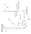
- FIG. 1 is a graph 100 that illustrates two aspects of portability efficacy for projection subsystems.
- the term "projection subsystem” refers to a light source, image forming device and associated refractive or reflective optical components such as lenses, mirrors, or beam splitters that are used to provide a projected optical image.
- a vertical axis 102 represents power efficiency of a projection subsystem in lumens for 1 watt of electrical power applied to the light source.
- a horizontal axis 104 represents a volume of a projection subsystem.
- Portability efficacy 108 increases as the efficiency increases, and increases as the volume decreases. Projection subsystems have increased portability when power efficiency is higher and the volume is smaller.
- Desired features for projection subsystems include a high level of optical flux in the projected image, large screen size, high contrast, large pixel content, and a wide color gamut.
- FIG. 1 illustrates one way of comparing some of these features for different optical systems.
- projection subsystems with incoherent light sources are able to provide useful combinations of the desired features.
- representative conventional projection subsystems A, C, D, and E are evaluated for power efficiency and size and mapped onto the graph 100.
- Subsystems A and C are generally superior to D and E in power efficiency and size, but they use coherent laser light sources that have drawbacks in terms of high cost, low image quality from laser speckle, and potential eye safety issues, particularly under electrical or mechanical fault conditions.
- Subsystems D and E use incoherent LED light sources, which may overcome the drawbacks of laser-based systems, but they are relatively large, low in power efficiency or both, leading to limited portability efficacy.
- the exemplary projection subsystem of the present invention is represented on graph 100 as projection subsystem B, which uses an incoherent light source and has smaller size and greater efficiency than subsystems D and E.
- Ambient lighting levels in projection environments do not scale down when a projector design is miniaturized or scaled down.
- a sufficient projection light power level is desired in order to provide a projection image that is bright enough for a group of viewers in the presence of ambient light. If the size of a light emitting source were to be miniaturized, for example, and the same electrical power level were to be applied to the smaller light emitting sources, increased temperature rises would be encountered in the smaller light emitting source that could cause overheating.
- high power solid state lasers that can efficiently produce highly collimated, coherent light might improve power efficiency, the use of coherent light may produce speckle, decreasing projected image quality. Also, the use of laser light raises concerns about eye safety, particularly under electrical or mechanical fault conditions.
- optical components are assembled in improved combinations to reach desired high levels of luminous flux with low levels of electrical power in a miniature projection subsystem.
- the use of coherent light sources is avoided.
- the portability efficacy of the projection subsystem is enhanced. In particular, many optical losses that typically occur when light passes through air between conventional projector optics components are avoided.
- Projection subsystems disclosed herein are capable of operation in a region 110 in graph 100 which has high portability efficacy.
- the region 110 is limited to a volume of no more than 14 cubic centimeters and an efficiency of no less than 3.8 lumens for 1 watt.
- Another measure of portability efficacy comprises a thickness of an projection subsystem along its thinnest axis.
- An projection subsystem is best suited for use in a pocket portable device when the projection subsystem has a thickness of less than 14 millimeters along a thickness axis.
- Another aspect of portability efficacy is luminous flux.
- An projection subsystem is best suited for use in a pocket portable device when the luminous flux is at least 3 lumens.
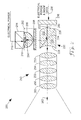
- FIG. 2 illustrates a projection subsystem 200.
- the projection subsystem 200 is useful for projecting still or video images from miniature electronic systems such as cell phones, personal digital assistants (PDA's), global positioning system (GPS) receivers.
- Projection subsystem 200 receives electrical power and image data from the miniature electronic system (not illustrated in FIG. 2 ) into which it is embedded.
- Projection subsystem 200 is useful as a component part of a miniature projector accessory for displaying computer video.
- Projection subsystem 200 is useful in systems that are small enough to be carried, when not in use, in a pocket of clothing, such as a shirt pocket.
- Images projected by the projection subsystem 200 can be projected onto a reflective projection screen, a light-colored painted wall, a whiteboard or sheet of paper or other known projection surfaces.
- Projection subsystem 200 can be embedded, for example, in a portable computer such as a laptop computer or a cell phone.
- Projection subsystem 200 comprises a light engine 202.
- the light engine 202 provides a light beam 204.
- the light engine includes a collection lens 206, a collimator 208 and a solid state light emitter 210.
- the collection lens 206 comprises a hyperhemispheric ball lens.
- the hyperhemispheric ball lens is arranged as taught in US Patent Publication US 2007/0152231 .
- the solid state light emitter 210 receives electrical power 212 with an electrical power level.
- the solid state emitter 210 thermally couples to a heat sink 214.
- the solid state light emitter provides an emitter light beam with an emitter luminous flux level.
- the light beam 204 comprises incoherent light.
- the light beam 204 comprises illumination that is a partially focussed image of the solid state light emitter 210.
- the solid state light emitter 210 comprises one or more light emitting diodes (LED's).
- the collection lens 206 comprises a hemispheric ball lens.
- the collimator 208 comprises a focusing unit comprising a first fresnel lens having a first non-faceted side for receiving a first non-collimated beam and a first faceted side for emitting the collimated beam; and a second fresnel lens having a second non faceted side for substantially directly receiving the collimated beam and second faceted side for emitting an output beam.
- the solid state light emitter 210 can be arranged as shown in US Provisional Application 60/820,883 .
- the light engine 202 can be arranged as shown in US Provisional Applications 60/820,887 , 60/820,888 , 60/821,032 , 60/838,988 .
- the projection subsystem 200 comprises a refractive body 220.
- the refractive body 220 receives the light beam 204.
- the refractive body 220 provides a polarized beam 222.
- the refractive body 220 includes an internal polarizing filter 224.
- One polarized component of the light beam 204 is reflected by the internal polarizing filter 224 to form the polarized beam 222.
- the refractive body is formed or utilized according to one or more aspects of US Patent Publication US 2007/0023941 A1 Duncan et al., US Patent Publication US 2007/0024981 A1 Duncan et al ., US Patent Publication US 2007/0085973 A1 Duncan et al ., and US Patent Publication US 2007/0030456 Duncan et al .
- the refractive body 220 comprises a first external lens surface 226 and a second external lens surface 228.
- the external lens surfaces 226, 228 have curved lens surfaces and have non-zero lens power.
- the external lens surface 226 comprises a convex lens surface that is useful in maintaining a small volume for the projection subsystem 200.
- the external lens surfaces 226, 228 are flat.
- the refractive body 220 comprises plastic resin material bodies 230, 232 on opposite sides of the internal polarizing filter 224.
- the internal polarizing filter 224 comprises a multilayer optical film.
- the refractive body 220 comprises a multifunction optical component that functions as a polarizing beam splitter as well as a lens. By combining the polarizing beam splitter and lens functions in a multifunction refractive body, losses that would otherwise occur at air interfaces between separate beam splitters and lenses are avoided.
- the projection subsystem 200 comprises an image-forming device 236.
- the image-forming device 236 receives image data on electrical input bus 238.
- the image-forming device 236 receives the polarized beam 222.
- the image-forming device 236 selectively reflects the polarized beam 222 according to the image data.
- the image-forming device 236 provides an image 240 with a polarization that is rotated relative to the polarization of the polarized beam 222.
- the image-forming device 236 provides the image 240 to the refractive body 220.
- the image 240 passes through the internal polarizing filter 224.
- the image-forming device 236 comprises a liquid crystal on silicon (LCOS) device.
- LCOS liquid crystal on silicon
- the projection subsystem 200 comprises a projection lens assembly 250.
- the projection lens assembly 250 comprises multiple lenses indicated schematically at 252, 254, 256, 258, 260.
- the projection lens assembly 250 receives the image 240 from the refractive body 220.
- the projection lens assembly 250 provides an image projection beam 262 having a projected luminous flux that is suitable for viewing.
- the projected luminous flux is no less than 3 lumens.
- a ratio of the projected luminous flux to the electrical power level is at least 3.8 lumens for 1 watt.
- the ratio of the projected luminous flux to electrical power level is at least 7 lumens per watt.
- the ratio of projected luminous flux to electrical power level is at least 10 lumens per watt.
- the collection efficiency ratio is at least 38.5%.
- the collection efficiency ratio is defined as a ratio of the polarized luminous flux impinging on an active surface of the image forming device 236 to the luminous flux emitted from the unpolarized solid state light emitter 210.
- the projection subsystem 200 has an electrical power level of no more than 3.6 watts. According to another aspect, the projection subsystem 200 has a volume of less than 14 cubic centimeters. According to another aspect, the projection subsystem 200 has a thickness of less than 14 millimeters.
- the projection subsystem 200 has an F number that is less than 2.4. According to another aspect, the projection subsystem has an ANSI contrast ratio of at least 30:1. According to another aspect, the projection subsystem has an ANSI contrast ratio of at least 50:1. According to another aspect, the projection subsystem has an on/off contrast ratio of at least 100:1.
- FIG. 3A illustrates a projection subsystem 300.
- Projection subsystem 300 is similar to projection subsystem 200 except that an anamorphic optical device 302 is included in the projection subsystem 300.
- Reference numbers used in FIG. 3A that are the same as reference number used in FIG. 2 represent the same or similar features.
- the projection subsystem 300 is similar to projection subsystem 200.
- the anamorphic optical device 302 alters an aspect ratio of a light beam 304.
- the anamorphic optic device 302 changes light beam shape to adapt a first aspect ratio in the light engine 202 to a second different aspect ratio in the refractive body 220. According to one aspect, the first aspect ratio is 1:1 and the second aspect ratio is 16:9.
- the first aspect ratio is 1:1 and the second aspect ratio is 4:3.
- the second aspect ratio matches an aspect ratio of the image forming device 236.
- the anamorphic optical device 302 comprises an anamorphic lens as illustrated in FIG. 3A .
- an anamorphic surface 306 provided on a refractive body 320 serves as an anamorphic optical device.
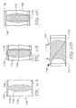
- the refractive body 320 is similar to the refractive body 220 in FIG. 3A .
- a polarization filter can be positioned at locations 330 or 332 in FIG. 3A .
- the polarization filter at location 330 or 332 enhances optical contrast ratio of the optical subsystem 300.
- the polarization filter positioned at locations 330, 332 comprises a multilayer optical film.
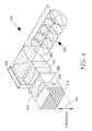
- FIG. 4 illustrates an oblique view of the projection subsystem 300 of FIG. 3 .
- the projection subsystem 300 has a thickness 402.
- the projection subsystem 300 has a cross-sectional area 400 which is indicated by a stippled planar surface that is perpendicular to the thickness 402.
- the cross-sectional area 400 includes the areas of components 206, 208, 236, 220, 250, 302 and intervening air spaces between the components which carry useful light.
- the projection subsystem 300 has a volume that is a mathematical product of the thickness 402 and the cross-sectional area 400.
- FIGS. 5A, 5B illustrate portions of projection subsystem 500, 510 that are similar to projection subsystem 200 or 300.
- Projection subsystem 500 includes a filter 502.
- the filter 502 is adjacent the collimator 208.
- the filter 502 comprises an optical component that is separate from the collimator 208.
- the filter 502 comprises a filter layer on the collimator 208.
- the collimator 208 is between the filter 502 and the lens 206 as illustrated in FIG. 5A .
- a filter 504 is between the collimator 208 and the lens 206.
- the filters 502, 504 comprise a blue blocking filter that also blocks ultraviolet (UV) radiation.
- the blue blocking filter blocks blue and ultraviolet light at wavelengths which tend to deteriorate refractive optical devices, while passing the portion of the blue spectrum desired to be present in the projected image.
- the filter 502 or 504 blocks undesired light from reaching the refractive body 220.
- FIGS. 5C, 5D illustrate portions of projection subsystem 520, 540 that are similar to projection subsystem 200 or 300.
- Projection subsystem 520 includes a filter 522.
- the filter 522 is positioned between the refractive body 220 and the projection lens assembly 250.
- Projection subsystem 540 includes a refractive body 220A that includes a filter 542 adjacent a polarizing filter 224.
- the filter 542 is positioned between the polarizing filter 224 and a plastic resin body 230.
- the filters 522, 542 comprise polarizing filters.
- the polarizing filters 522, 542 increase the contrast of the projected image.
- a projection subsystem according to FIG. 5D is described in US Patent Application titled "Polarizing Beam Splitters Incorporating Reflective and Absorptive Polarizers and Image Display Systems Thereof," identified as Application Serial No. 11/457,599 .
- FIG. 6 illustrates a projection subsystem 600 that is similar to projection subsystem 300 in FIG. 4 except that projection subsystem 600 comprises a plate heat sink 602 whereas projection subsystem 300 in FIG. 4 comprises a heat sink 214 that has protrusions such as fins or pins.
- projection subsystem 600 is similar to projection subsystem 300.
- the plate heat sink 602 has a lower plate surface 604 that is exposed at an outer package surface of a pocket portable electronic package such as a cell phone, personal digital assistant (PDA), global positioning system (GPS) or similar pocket device.
- the plate heat sink 602 makes thermal contact to other elements in the electronic device to dissipate the heat.
- the lower plate surface 604 can be place in contact with an accessory external heat sink for extended use.
- FIG. 7 illustrates a projection subsystem 700 that is similar to the projection subsystem 300 in FIG. 3A , except that the projection subsystem 700 includes a polarization film 702 disposed along an optical path between the collection lens 206 and the refractive body 220.
- the polarization film 702 is disposed between a collimator 208 and the refractive body 220 as illustrated in FIG. 7 .
- the polarization film 702 reflects polarized light back toward the reflective surface of a solid state light emitter 210 to provide light recycling. Inclusion of the polarization film 702 increases the luminous flux of the projection subsystem.
- polarization recycling is as described in US Patent Application 11/772,609 filed July 2, 2007 .
- FIG. 8 illustrates a projection subsystem 800 that is similar to the projection subsystems of FIGS. 3A , 7 .
- the projection subsystem 800 includes an enclosure 802 that encloses at least portions of the optical components 206, 208, 702, 302, 220 and protects optical component surfaces from contamination and moisture.
- the enclosure 802 may include an air filter 806.
- the air filter 806 restricts flow of air, filters out contamination and equalizes pressure between an interior of the enclosure 802 and the surrounding atmosphere.
- the air filter 806 includes a dessicant 808 that reduces humidity inside the enclosure 802.
- the enclosure 802 serves a mechanical mounting for optical components.
- the enclosure 802 is coupled to a lens assembly guide tube 804.
- a projection lens assembly 250 is slidably mounted in the guide tube 804.
- the projection lens assembly 250 includes an actuation lever 810 that can be mechanically actuated to move the position of the projection lens assembly 250 relative to the image forming device 236.
- the movement of the projection lens assembly 250 comprises a focus adjustment.
- the projection lens assembly 250 fits closely in the guide tube 804 to provide a seal that prevents entry of contamination into the enclosure 802.
- one or more O-rings are provided between the projection lens assembly and the guide tube 804 to provide a seal.
- a bellows (not illustrated) is provided between an end of the projection lens assembly 250 and the guide tube 804 to provide a seal.
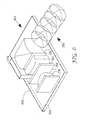
- FIG. 9 illustrates an oblique view of a projection subsystem 900 that is similar to the projection subsystem shown in FIG. 2 .
- the projection subsystem 900 comprises a solid state light emitter (not visible in FIG. 9 ) that is connected by electrical leads 902, 904 to a source of electrical power.
- the solid state light emitter is thermally coupled to a heat sink 906.
- the projection subsystem 900 includes a collection lens 908.
- the projection subsystem 900 includes an image forming device 912, a refractive body 914 and a projection lens 916.
- FIG. 10A illustrates a light emitting diode 1000 that serves as an exemplary solid state light emitter, such as solid state light emitter 210 in FIG. 2 .
- the light emitting diode 1000 is connected to electrical power by way of bond wires 1002, 1004.
- the light emitting diode 1000 includes light emitting regions 1008, 1010, 1012, 1014, 1016.
- Other regions of the light emitting diode 1000, such as regions 1018, 1020, 1022, 1024, 1026, 1028 comprise dark regions that include electrical conductor and that do not generate light.
- the image of the light emitting diode 1000 is thus a pattern of regions that generate light and regions that do not generate light.
- an image is desired that is relatively uniform in brightness such as illustrated in FIG. 10B . According to one aspect, providing the uniform brightness is as taught in US Patent Publication 2007/0153397 titled "PROJECTION SYSTEM WITH BEAM HOMOGENIZER.”
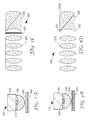
- FIG. 11A illustrates an example of mounting an optical component in a projection subsystem.
- a molded component 1100 comprises an optical portion 1102 along an optical axis 1104 and a mounting flange portion 1106 that is molded in a unitary structure with the optical portion 1102.
- Optical portion 1102 comprises a lens, however, any of the optical components of the projection subsystem can be used in place of the lens.
- the molded component is molded from refractive material such as transparent plastic resin.
- the mounting flange portion 1106 has rims 1108. 1110 that are shaped to mate with flanges of adjacent molded components. Rims can be attached to one another by friction fit, snap fit, gluing, threads or other known attachment methods for plastic resin molded components.
- FIG. 11B illustrates an example of mounting an optical component in a projection subsystem.
- An optical component 1120 is captured in grooves 1122, 1124 of mating halves of a mounting tube 1126. Multiple optical components mount in the mounting tube.
- the mounting tube 1126 is assembled along a parting line 1128.
- Optical portion 1120 comprises a lens, however, any of the optical components of the projection subsystem can be similarly mounted in place of the lens.
- FIG. 11C illustrates an example of mounting an optical component in a projection subsystem.
- An optical component 1130 is captured in a groove 1132 of a mounting channel 1134.
- a lid 1136 is secured to the mounting channel.
- Multiple optical components mount in the mounting channel 1134.
- the mounting channel 1134 and the lid 1136 are assembled along a parting line 1138.
- Optical portion 1130 comprises a lens, however, any of the optical components of the projection subsystem can be similarly mounted in place of the lens.
- FIG. 11D illustrates an example of a combination of a refractive body 1150 (such as refractive body 220 of FIG. 2 ) molded together with mounting flange rims 1152, 1154, 1156 similar to those shown in FIG. 11A .
- a refractive body 1150 such as refractive body 220 of FIG. 2
- mounting flange rims 1152, 1154, 1156 similar to those shown in FIG. 11A .
- FIGS. 12A, 12B illustrate alternative embodiments of projection subsystems that have portability efficacy as described above.
- FIG. 12A illustrates a projection subsystem 1202 that includes a light engine 1204, an image-forming device 1206 and a projection lens assembly 1208.
- the image-forming device 1206 comprises a transmissive image forming device.
- FIG. 12B illustrates a projection subsystem 1222 that includes a light engine 124, an image-forming device 1226, an anamorphic lens 1228 and a projection lens assembly 1230.
- the image forming device 1226 is a reflective image forming device, such as an array of deflectable mirror pixels, and does not require polarized light for its operation.
- a projection subsystem is constructed similar to FIGS. 7 and 9 , with a refractive body similar to FIG. 3B .
- the solid state light emitter is a white LED made with a blue InGaN die, part number C450-EZ1000-S30000, plus a conformal yellow phosphor, produced by Cree, Inc. (4600 Silicon Drive, Durham, NC 27703).
- the collection lens, and its coupling to the LED, is described in US Patent Publication US 2007/0152231 .
- the collimator is a Fresnel lens having a non-faceted side for receiving the non-collimated beam and a faceted side for emitting the collimated beam.
- the refractive body is a molded plastic polarizing beam splitter (PBS) as described in US Patent Publication US 2007/0024981 .
- the reflective polarizing films are manufactured by 3M Company (St. Paul, MN 55144) under the trade designation "VIKUITI" advanced polarizing films (APF).
- the image-forming device is an LCOS microdisplay with internal red, green and blue color filters, part number HX7007ATBFA, produced by Himax Display (2F, No.26, Zih Lian Road, Tree Valley Park, Sinshih, Tainan County 74445, Taiwan).
Landscapes
- Physics & Mathematics (AREA)
- General Physics & Mathematics (AREA)
- Optics & Photonics (AREA)
- Engineering & Computer Science (AREA)
- Multimedia (AREA)
- Polarising Elements (AREA)
- Projection Apparatus (AREA)
- Non-Portable Lighting Devices Or Systems Thereof (AREA)
Applications Claiming Priority (8)
| Application Number | Priority Date | Filing Date | Title |
|---|---|---|---|
| US82088306P | 2006-07-31 | 2006-07-31 | |
| US82088706P | 2006-07-31 | 2006-07-31 | |
| US82089406P | 2006-07-31 | 2006-07-31 | |
| US82088806P | 2006-07-31 | 2006-07-31 | |
| US82103206P | 2006-08-01 | 2006-08-01 | |
| US83898806P | 2006-08-21 | 2006-08-21 | |
| US11/772,609 US8075140B2 (en) | 2006-07-31 | 2007-07-02 | LED illumination system with polarization recycling |
| EP07840611A EP2049947A1 (de) | 2006-07-31 | 2007-07-31 | Optisches projektionssubsystem |
Related Parent Applications (1)
| Application Number | Title | Priority Date | Filing Date |
|---|---|---|---|
| EP07840611.3 Division | 2007-07-31 |
Publications (1)
| Publication Number | Publication Date |
|---|---|
| EP2642338A2 true EP2642338A2 (de) | 2013-09-25 |
Family
ID=38997798
Family Applications (2)
| Application Number | Title | Priority Date | Filing Date |
|---|---|---|---|
| EP07813576A Withdrawn EP2062087A4 (de) | 2006-07-31 | 2007-07-31 | Led-beleuchtungssystem mit polarisations-recycling |
| EP13172219.1A Withdrawn EP2642338A2 (de) | 2006-07-31 | 2007-07-31 | Optisches Subsystem zur Projektion |
Family Applications Before (1)
| Application Number | Title | Priority Date | Filing Date |
|---|---|---|---|
| EP07813576A Withdrawn EP2062087A4 (de) | 2006-07-31 | 2007-07-31 | Led-beleuchtungssystem mit polarisations-recycling |
Country Status (6)
| Country | Link |
|---|---|
| US (1) | US8075140B2 (de) |
| EP (2) | EP2062087A4 (de) |
| JP (1) | JP2009545855A (de) |
| KR (1) | KR20090034363A (de) |
| TW (1) | TW200817821A (de) |
| WO (1) | WO2008016903A2 (de) |
Families Citing this family (24)
| Publication number | Priority date | Publication date | Assignee | Title |
|---|---|---|---|---|
| TW200819899A (en) * | 2006-07-31 | 2008-05-01 | 3M Innovative Properties Co | Combination camera/projector system |
| JP5330993B2 (ja) | 2006-07-31 | 2013-10-30 | スリーエム イノベイティブ プロパティズ カンパニー | 光学投影サブシステム |
| US8075140B2 (en) * | 2006-07-31 | 2011-12-13 | 3M Innovative Properties Company | LED illumination system with polarization recycling |
| US20080036972A1 (en) * | 2006-07-31 | 2008-02-14 | 3M Innovative Properties Company | Led mosaic |
| WO2008016908A2 (en) | 2006-07-31 | 2008-02-07 | 3M Innovative Properties Company | Led source with hollow collection lens |
| KR101328960B1 (ko) * | 2007-11-05 | 2013-11-14 | 엘지전자 주식회사 | 프로젝터 |
| US8382293B2 (en) * | 2008-05-05 | 2013-02-26 | 3M Innovative Properties Company | Light source module |
| EP2550479B1 (de) * | 2010-03-22 | 2015-09-23 | Robe Lighting, Inc | Linsensystem für einen led-beleuchtungskörper |
| US8639306B2 (en) | 2011-02-07 | 2014-01-28 | Brien Holden Vision Diagnostics, Inc. | Noninvasive eye-property monitoring, including aqueous-humor glucose monitoring as an indication of blood glucose level |
| EP2680741A4 (de) | 2011-03-02 | 2014-08-27 | Brien Holden Vision Diagnostics Inc | Netzhautkamerasystem und methodologie dafür |
| US9033534B2 (en) * | 2011-04-20 | 2015-05-19 | Jasper Ridge Inc. | Hands-free vision aid |
| DE102011107893A1 (de) * | 2011-07-18 | 2013-01-24 | Heraeus Noblelight Gmbh | Optoelektronisches Modul mit verbesserter Optik |
| US9500340B2 (en) | 2011-10-25 | 2016-11-22 | A-Dec, Inc. | Dental light using LEDs |
| KR20140115322A (ko) * | 2012-01-09 | 2014-09-30 | 웨이비엔, 인코포레이티드 | 초선명 역광 lcd 비디오 디스플레이 |
| US8987658B2 (en) * | 2012-11-28 | 2015-03-24 | Intersil Americas LLC | Packaged light detector semiconductor devices with non-imaging optical concentrators for ambient light and/or optical proxmity sensing, methods for manufacturing the same, and systems including the same |
| US20140211173A1 (en) * | 2013-01-30 | 2014-07-31 | 3M Innovative Properties Company | Optical projection subsystem |
| US9507066B2 (en) | 2014-06-30 | 2016-11-29 | Microsoft Technology Licensing, Llc | Eyepiece for near eye display system |
| JP6759212B2 (ja) * | 2014-12-31 | 2020-09-23 | スリーエム イノベイティブ プロパティズ カンパニー | 小型の投影システム及び関係する構成要素 |
| CN108255004B (zh) * | 2016-12-28 | 2021-03-30 | 佳能株式会社 | 光源装置和图像投影装置 |
| CN108761981B (zh) * | 2018-04-28 | 2020-10-20 | 苏州佳世达光电有限公司 | 投影机 |
| WO2020144983A1 (ja) * | 2019-01-07 | 2020-07-16 | ソニー株式会社 | 光源装置及び画像表示装置 |
| CN111273455A (zh) * | 2019-12-12 | 2020-06-12 | 河北汉光重工有限责任公司 | 一种可见光/红外复合镜头的装调方法 |
| JP2021120728A (ja) * | 2020-01-31 | 2021-08-19 | カシオ計算機株式会社 | 蛍光発光装置、光源装置及び投影装置 |
| EP4427096A4 (de) | 2021-11-03 | 2025-09-03 | Lumileds Llc | Aktuator zur unschärfe dunkler bänder in einer beleuchtung |
Citations (5)
| Publication number | Priority date | Publication date | Assignee | Title |
|---|---|---|---|---|
| US20070024981A1 (en) | 2005-07-29 | 2007-02-01 | Duncan John E | Polarizing beam splitter |
| US20070023941A1 (en) | 2005-07-29 | 2007-02-01 | Duncan John E | Method for making polarizing beam splitters |
| US20070030456A1 (en) | 2005-07-29 | 2007-02-08 | Duncan John E | Polarizing beam splitter |
| US20070153397A1 (en) | 2005-12-30 | 2007-07-05 | Destain Patrick R | Projection system with beam homogenizer |
| US20070152231A1 (en) | 2005-12-30 | 2007-07-05 | Destain Patrick R | LED with compound encapsulant lens |
Family Cites Families (129)
| Publication number | Priority date | Publication date | Assignee | Title |
|---|---|---|---|---|
| US5084807A (en) * | 1986-08-22 | 1992-01-28 | U.S. Philips Corporation | Illumination system for LCD projection television |
| US5108172A (en) * | 1989-08-11 | 1992-04-28 | Raf Electronics Corp. | Active matrix reflective image plane module and projection system |
| US5022750A (en) * | 1989-08-11 | 1991-06-11 | Raf Electronics Corp. | Active matrix reflective projection system |
| US6188460B1 (en) * | 1990-06-11 | 2001-02-13 | Reveo, Inc. | Image display panel having a backlighting structure and a single-layer pixelated aray of reflective-type spectral filtering elements where between light is recycled for producing color images with enhanced brightness |
| DE9202608U1 (de) * | 1992-02-28 | 1992-09-17 | EBT Licht-Technik GmbH, 6702 Bad Dürkheim | Anzeigeelement |
| US5335158A (en) * | 1992-05-21 | 1994-08-02 | Eastman Kodak Company | High efficiency linear light source |
| US6832724B2 (en) * | 1993-03-26 | 2004-12-21 | Symbol Technologies, Inc. | Electro-optical assembly for image projection, especially in portable instruments |
| JPH06309842A (ja) * | 1993-04-26 | 1994-11-04 | Sony Corp | 編集装置 |
| US5882774A (en) | 1993-12-21 | 1999-03-16 | Minnesota Mining And Manufacturing Company | Optical film |
| JPH0876082A (ja) * | 1994-06-28 | 1996-03-22 | Sharp Corp | 投影表示装置 |
| US5625738A (en) * | 1994-06-28 | 1997-04-29 | Corning Incorporated | Apparatus for uniformly illuminating a light valve |
| TW324818B (en) | 1995-09-18 | 1998-01-11 | Motorola Inc | Multi-mode image manifestation apparatus |
| US5592578A (en) * | 1995-11-01 | 1997-01-07 | Hewlett-Packard Company | Peripheral optical element for redirecting light from an LED |
| EP0817157A3 (de) * | 1996-06-28 | 1998-08-12 | Texas Instruments Incorporated | Bildanzeigesystemen |
| US5975703A (en) * | 1996-09-30 | 1999-11-02 | Digital Optics International | Image projection system |
| US6486997B1 (en) * | 1997-10-28 | 2002-11-26 | 3M Innovative Properties Company | Reflective LCD projection system using wide-angle Cartesian polarizing beam splitter |
| JP3614001B2 (ja) | 1997-12-03 | 2005-01-26 | セイコーエプソン株式会社 | 投影装置 |
| US6050690A (en) * | 1998-01-08 | 2000-04-18 | Siemens Information And Communication Networks, Inc. | Apparatus and method for focusing a projected image |
| US6091085A (en) * | 1998-02-19 | 2000-07-18 | Agilent Technologies, Inc. | GaN LEDs with improved output coupling efficiency |
| JPH11282083A (ja) * | 1998-03-27 | 1999-10-15 | Minolta Co Ltd | プロジェクター装置 |
| JP3585097B2 (ja) * | 1998-06-04 | 2004-11-04 | セイコーエプソン株式会社 | 光源装置,光学装置および液晶表示装置 |
| TW406442B (en) * | 1998-07-09 | 2000-09-21 | Sumitomo Electric Industries | White colored LED and intermediate colored LED |
| US6204523B1 (en) * | 1998-11-06 | 2001-03-20 | Lumileds Lighting, U.S., Llc | High stability optical encapsulation and packaging for light-emitting diodes in the green, blue, and near UV range |
| JP3385238B2 (ja) * | 1999-01-12 | 2003-03-10 | シャープ株式会社 | 光送受信モジュール |
| US6573978B1 (en) * | 1999-01-26 | 2003-06-03 | Mcguire, Jr. James P. | EUV condenser with non-imaging optics |
| US6200002B1 (en) * | 1999-03-26 | 2001-03-13 | Philips Electronics North America Corp. | Luminaire having a reflector for mixing light from a multi-color array of leds |
| DE19918370B4 (de) * | 1999-04-22 | 2006-06-08 | Osram Opto Semiconductors Gmbh | LED-Weißlichtquelle mit Linse |
| CN100426050C (zh) | 1999-07-26 | 2008-10-15 | 拉博斯费尔株式会社 | 体积型透镜、发光体、照明器具及光信息系统 |
| US6384406B1 (en) | 1999-08-05 | 2002-05-07 | Microvision, Inc. | Active tuning of a torsional resonant structure |
| US6488976B1 (en) * | 1999-12-13 | 2002-12-03 | Affinitea Brewing Technologies, Inc. | Method and apparatus for brewing tea with an espresso machine |
| US6486499B1 (en) | 1999-12-22 | 2002-11-26 | Lumileds Lighting U.S., Llc | III-nitride light-emitting device with increased light generating capability |
| JP3823659B2 (ja) * | 2000-02-04 | 2006-09-20 | セイコーエプソン株式会社 | プロジェクタ |
| US6224216B1 (en) | 2000-02-18 | 2001-05-01 | Infocus Corporation | System and method employing LED light sources for a projection display |
| US6527411B1 (en) * | 2000-08-01 | 2003-03-04 | Visteon Corporation | Collimating lamp |
| JP3497805B2 (ja) * | 2000-08-29 | 2004-02-16 | オリンパス株式会社 | 画像投影表示装置 |
| TW446848B (en) | 2000-11-29 | 2001-07-21 | Acer Comm & Amp Multimedia Inc | Projection system for automatically adjusting focal length and method thereof |
| US6772265B2 (en) * | 2000-12-11 | 2004-08-03 | International Business Machines Corporation | Docking station for a laptop computer |
| US6547416B2 (en) * | 2000-12-21 | 2003-04-15 | Koninklijke Philips Electronics N.V. | Faceted multi-chip package to provide a beam of uniform white light from multiple monochrome LEDs |
| US6639706B2 (en) * | 2001-01-24 | 2003-10-28 | Kollsman, Inc. | Optical path switch and method of using thereof |
| JP2002222989A (ja) | 2001-01-26 | 2002-08-09 | Toshiba Corp | 半導体発光素子 |
| US20020176015A1 (en) | 2001-05-23 | 2002-11-28 | Lichtfuss Hans A. | Image capturing camera and projector device |
| US6916440B2 (en) | 2001-05-31 | 2005-07-12 | 3M Innovative Properties Company | Processes and apparatus for making transversely drawn films with substantially uniaxial character |
| US6672721B2 (en) * | 2001-06-11 | 2004-01-06 | 3M Innovative Properties Company | Projection system having low astigmatism |
| US6609795B2 (en) * | 2001-06-11 | 2003-08-26 | 3M Innovative Properties Company | Polarizing beam splitter |
| US6793344B2 (en) | 2001-06-26 | 2004-09-21 | Integrated Microdisplays Limited | Optical systems for liquid crystal display projectors |
| US6856466B2 (en) * | 2001-07-05 | 2005-02-15 | Science & Engineering Associates, Inc. | Multiple imaging system |
| US6791749B2 (en) * | 2001-08-29 | 2004-09-14 | Delpico Joseph | Polarized exposure for web manufacture |
| JP3948650B2 (ja) * | 2001-10-09 | 2007-07-25 | アバゴ・テクノロジーズ・イーシービーユー・アイピー(シンガポール)プライベート・リミテッド | 発光ダイオード及びその製造方法 |
| US7072096B2 (en) * | 2001-12-14 | 2006-07-04 | Digital Optics International, Corporation | Uniform illumination system |
| TW571119B (en) * | 2001-12-20 | 2004-01-11 | Delta Electronics Inc | Image projection device with integrated semiconductor light emitting element light source |
| US6719426B2 (en) * | 2002-02-28 | 2004-04-13 | 3M Innovative Properties Company | Compound polarization beam splitters |
| JP3991764B2 (ja) | 2002-05-10 | 2007-10-17 | セイコーエプソン株式会社 | 照明装置および投射型表示装置 |
| CA2427559A1 (en) | 2002-05-15 | 2003-11-15 | Sumitomo Electric Industries, Ltd. | White color light emitting device |
| EP1387211B1 (de) | 2002-07-15 | 2005-05-25 | Sony International (Europe) GmbH | Bildaufnahmegerät kombiniert mit der Möglichkeit der Bildprojektion |
| US7306603B2 (en) * | 2002-08-21 | 2007-12-11 | Innovative Spinal Technologies | Device and method for percutaneous placement of lumbar pedicle screws and connecting rods |
| US7479662B2 (en) * | 2002-08-30 | 2009-01-20 | Lumination Llc | Coated LED with improved efficiency |
| JP4078159B2 (ja) * | 2002-09-11 | 2008-04-23 | キヤノン株式会社 | 投射型表示装置および画像表示システム |
| US6936209B2 (en) * | 2002-11-27 | 2005-08-30 | 3M Innovative Properties Company | Methods and devices for processing polymer films |
| US6949212B2 (en) * | 2002-11-27 | 2005-09-27 | 3M Innovative Properties Company | Methods and devices for stretching polymer films |
| WO2004068182A2 (en) * | 2003-01-24 | 2004-08-12 | Digital Optics International Corporation | High density illumination system |
| US7312560B2 (en) * | 2003-01-27 | 2007-12-25 | 3M Innovative Properties | Phosphor based light sources having a non-planar long pass reflector and method of making |
| US7091661B2 (en) * | 2003-01-27 | 2006-08-15 | 3M Innovative Properties Company | Phosphor based light sources having a reflective polarizer |
| US20040218387A1 (en) | 2003-03-18 | 2004-11-04 | Robert Gerlach | LED lighting arrays, fixtures and systems and method for determining human color perception |
| JP4082332B2 (ja) * | 2003-04-11 | 2008-04-30 | セイコーエプソン株式会社 | 表示装置およびプロジェクタ |
| FI20030583A7 (fi) * | 2003-04-16 | 2004-10-17 | Upstream Eng Oy | Dataprojektori |
| US7152977B2 (en) * | 2003-04-24 | 2006-12-26 | Qubic Light Corporation | Solid state light engine optical system |
| DE10319274A1 (de) | 2003-04-29 | 2004-12-02 | Osram Opto Semiconductors Gmbh | Lichtquelle |
| US7237899B2 (en) | 2003-05-16 | 2007-07-03 | 3M Innovative Properties Company | Highly efficient single panel and two panel projection engines |
| US6869206B2 (en) * | 2003-05-23 | 2005-03-22 | Scott Moore Zimmerman | Illumination systems utilizing highly reflective light emitting diodes and light recycling to enhance brightness |
| US6903382B2 (en) * | 2003-07-07 | 2005-06-07 | Lightop Technology Co., Ltd. | Light emitting diode mounting structure |
| US7391153B2 (en) * | 2003-07-17 | 2008-06-24 | Toyoda Gosei Co., Ltd. | Light emitting device provided with a submount assembly for improved thermal dissipation |
| US6981642B2 (en) * | 2003-07-17 | 2006-01-03 | Symbol Technologies, Inc. | Non-parallax optical auto-focusing system and method |
| US7009213B2 (en) * | 2003-07-31 | 2006-03-07 | Lumileds Lighting U.S., Llc | Light emitting devices with improved light extraction efficiency |
| US7717589B2 (en) * | 2003-11-25 | 2010-05-18 | Panasonic Electric Works Co., Ltd. | Light emitting device using light emitting diode chip |
| US7403680B2 (en) * | 2003-12-02 | 2008-07-22 | 3M Innovative Properties Company | Reflective light coupler |
| EP1693614B1 (de) | 2003-12-10 | 2009-12-16 | Okaya Electric Industries Co., Ltd. | Anzeigelampe |
| US20050135113A1 (en) * | 2003-12-18 | 2005-06-23 | Harvatek Corporation | Optical projection device of a colored lighting module |
| US7164811B2 (en) | 2004-02-09 | 2007-01-16 | Northrop Grumman Corporation | Pocket-pen ultra-high resolution MEMS projection display in combination with on-axis CCD image capture system including means for permitting 3-D imaging |
| US7300177B2 (en) * | 2004-02-11 | 2007-11-27 | 3M Innovative Properties | Illumination system having a plurality of light source modules disposed in an array with a non-radially symmetrical aperture |
| US7246923B2 (en) * | 2004-02-11 | 2007-07-24 | 3M Innovative Properties Company | Reshaping light source modules and illumination systems using the same |
| US20050179041A1 (en) * | 2004-02-18 | 2005-08-18 | Lumileds Lighting U.S., Llc | Illumination system with LEDs |
| TWI241042B (en) | 2004-03-11 | 2005-10-01 | Chen-Lun Hsingchen | A low thermal resistance LED device |
| US7215882B2 (en) * | 2004-07-21 | 2007-05-08 | Angatrom, Inc. | High-speed automatic focusing system |
| JP2005283663A (ja) | 2004-03-26 | 2005-10-13 | Canon Inc | 表示光学系および画像投射装置 |
| US7133211B2 (en) | 2004-04-02 | 2006-11-07 | Integrated Microdisplays Limited | Projector with flat light sources |
| GB2413858A (en) | 2004-05-06 | 2005-11-09 | * Agilent Technologies, Inc. | Optical beam-splitter with plano convex lens |
| US7101050B2 (en) | 2004-05-14 | 2006-09-05 | 3M Innovative Properties Company | Illumination system with non-radially symmetrical aperture |
| US7456499B2 (en) | 2004-06-04 | 2008-11-25 | Cree, Inc. | Power light emitting die package with reflecting lens and the method of making the same |
| US7280288B2 (en) | 2004-06-04 | 2007-10-09 | Cree, Inc. | Composite optical lens with an integrated reflector |
| DE102004031732A1 (de) * | 2004-06-30 | 2006-01-19 | Osram Opto Semiconductors Gmbh | Strahlungsemittierender Halbleiterchip mit einem Strahlformungselement und Strahlformungselement |
| EP2418522A1 (de) * | 2004-07-06 | 2012-02-15 | RealD Inc. | Beleuchtungssysteme |
| KR100638611B1 (ko) * | 2004-08-12 | 2006-10-26 | 삼성전기주식회사 | 다중 렌즈 발광 다이오드 |
| US7390097B2 (en) * | 2004-08-23 | 2008-06-24 | 3M Innovative Properties Company | Multiple channel illumination system |
| US20060055838A1 (en) * | 2004-09-13 | 2006-03-16 | Eastman Kodak Company | Light recycling film and display |
| US7352124B2 (en) * | 2004-09-28 | 2008-04-01 | Goldeneye, Inc. | Light recycling illumination systems utilizing light emitting diodes |
| WO2006035391A1 (en) * | 2004-09-30 | 2006-04-06 | Koninklijke Philips Electronics N.V. | Brightness enhancement of led using selective ray angular recycling |
| KR101080355B1 (ko) * | 2004-10-18 | 2011-11-04 | 삼성전자주식회사 | 발광다이오드와 그 렌즈 |
| US7255448B2 (en) * | 2004-10-20 | 2007-08-14 | Hewlett-Packard Development Company, L.P. | Pixelated color management display |
| US7304425B2 (en) * | 2004-10-29 | 2007-12-04 | 3M Innovative Properties Company | High brightness LED package with compound optical element(s) |
| US7329982B2 (en) * | 2004-10-29 | 2008-02-12 | 3M Innovative Properties Company | LED package with non-bonded optical element |
| US20060091411A1 (en) * | 2004-10-29 | 2006-05-04 | Ouderkirk Andrew J | High brightness LED package |
| US7330319B2 (en) * | 2004-10-29 | 2008-02-12 | 3M Innovative Properties Company | High brightness LED package with multiple optical elements |
| US7352011B2 (en) * | 2004-11-15 | 2008-04-01 | Philips Lumileds Lighting Company, Llc | Wide emitting lens for LED useful for backlighting |
| US7745814B2 (en) * | 2004-12-09 | 2010-06-29 | 3M Innovative Properties Company | Polychromatic LED's and related semiconductor devices |
| US20060232578A1 (en) | 2004-12-21 | 2006-10-19 | Silviu Reinhorn | Collapsible portable display |
| US7168820B1 (en) * | 2004-12-21 | 2007-01-30 | Djirair Minassian | Lighted vase |
| US20060139575A1 (en) * | 2004-12-23 | 2006-06-29 | Upstream Engineering Oy | Optical collection and distribution system and method |
| US7543941B2 (en) * | 2004-12-23 | 2009-06-09 | Cooper Technologies Company | Light zoom source using light emitting diodes and an improved method of collecting the energy radiating from them |
| EP1840977A4 (de) | 2004-12-24 | 2009-07-29 | Kyocera Corp | Lichtquelle und beleuchtungseinrichtung |
| US20060139580A1 (en) * | 2004-12-29 | 2006-06-29 | Conner Arlie R | Illumination system using multiple light sources with integrating tunnel and projection systems using same |
| US7692207B2 (en) * | 2005-01-21 | 2010-04-06 | Luminus Devices, Inc. | Packaging designs for LEDs |
| US7422330B2 (en) | 2005-03-30 | 2008-09-09 | 3M Innovative Properties Company | Illumination system and projection system using same |
| US7445340B2 (en) | 2005-05-19 | 2008-11-04 | 3M Innovative Properties Company | Polarized, LED-based illumination source |
| US7410261B2 (en) | 2005-05-20 | 2008-08-12 | 3M Innovative Properties Company | Multicolor illuminator system |
| CN100438026C (zh) * | 2005-09-16 | 2008-11-26 | 鸿富锦精密工业(深圳)有限公司 | 白光发光二极管及其制造方法 |
| US7540616B2 (en) * | 2005-12-23 | 2009-06-02 | 3M Innovative Properties Company | Polarized, multicolor LED-based illumination source |
| US20070153402A1 (en) * | 2005-12-30 | 2007-07-05 | Destain Patrick R | Fresnel lens combination |
| US7463417B2 (en) * | 2006-02-13 | 2008-12-09 | 3M Innovative Properties Company | Optical articles from curable compositions |
| US20070191506A1 (en) * | 2006-02-13 | 2007-08-16 | 3M Innovative Properties Company | Curable compositions for optical articles |
| US20090128781A1 (en) * | 2006-06-13 | 2009-05-21 | Kenneth Li | LED multiplexer and recycler and micro-projector incorporating the Same |
| US20070297052A1 (en) * | 2006-06-26 | 2007-12-27 | Bin Wang | Cube wire-grid polarizing beam splitter |
| US20070296921A1 (en) * | 2006-06-26 | 2007-12-27 | Bin Wang | Projection display with a cube wire-grid polarizing beam splitter |
| JP5330993B2 (ja) * | 2006-07-31 | 2013-10-30 | スリーエム イノベイティブ プロパティズ カンパニー | 光学投影サブシステム |
| TW200819899A (en) * | 2006-07-31 | 2008-05-01 | 3M Innovative Properties Co | Combination camera/projector system |
| US8075140B2 (en) * | 2006-07-31 | 2011-12-13 | 3M Innovative Properties Company | LED illumination system with polarization recycling |
| US20080231953A1 (en) * | 2007-03-22 | 2008-09-25 | Young Garrett J | System and Method for LED Polarization Recycling |
| US20080231780A1 (en) * | 2007-03-22 | 2008-09-25 | Sabic Innovative Plastics Ip Bv | Low-absorptive diffuser sheet and film stacks for direct-lit backlighting |
| US8540375B2 (en) * | 2007-11-30 | 2013-09-24 | Texas Instruments Incorporated | Offset projection distortion correction |
| US20090310042A1 (en) * | 2008-06-16 | 2009-12-17 | Marcial Vidal | Illumination system and method with efficient polarization recovery |
-
2007
- 2007-07-02 US US11/772,609 patent/US8075140B2/en not_active Expired - Fee Related
- 2007-07-31 KR KR1020097001943A patent/KR20090034363A/ko not_active Ceased
- 2007-07-31 EP EP07813576A patent/EP2062087A4/de not_active Withdrawn
- 2007-07-31 TW TW096128130A patent/TW200817821A/zh unknown
- 2007-07-31 EP EP13172219.1A patent/EP2642338A2/de not_active Withdrawn
- 2007-07-31 WO PCT/US2007/074823 patent/WO2008016903A2/en not_active Ceased
- 2007-07-31 JP JP2009523010A patent/JP2009545855A/ja not_active Withdrawn
Patent Citations (6)
| Publication number | Priority date | Publication date | Assignee | Title |
|---|---|---|---|---|
| US20070024981A1 (en) | 2005-07-29 | 2007-02-01 | Duncan John E | Polarizing beam splitter |
| US20070023941A1 (en) | 2005-07-29 | 2007-02-01 | Duncan John E | Method for making polarizing beam splitters |
| US20070030456A1 (en) | 2005-07-29 | 2007-02-08 | Duncan John E | Polarizing beam splitter |
| US20070085973A1 (en) | 2005-07-29 | 2007-04-19 | 3M Innovative Properties Company | Polarizing beam splitter |
| US20070153397A1 (en) | 2005-12-30 | 2007-07-05 | Destain Patrick R | Projection system with beam homogenizer |
| US20070152231A1 (en) | 2005-12-30 | 2007-07-05 | Destain Patrick R | LED with compound encapsulant lens |
Also Published As
| Publication number | Publication date |
|---|---|
| EP2062087A4 (de) | 2012-08-01 |
| KR20090034363A (ko) | 2009-04-07 |
| TW200817821A (en) | 2008-04-16 |
| WO2008016903A3 (en) | 2008-03-20 |
| US8075140B2 (en) | 2011-12-13 |
| JP2009545855A (ja) | 2009-12-24 |
| US20090116214A1 (en) | 2009-05-07 |
| EP2062087A2 (de) | 2009-05-27 |
| WO2008016903A2 (en) | 2008-02-07 |
Similar Documents
| Publication | Publication Date | Title |
|---|---|---|
| US7901083B2 (en) | Optical projection subsystem | |
| EP2642338A2 (de) | Optisches Subsystem zur Projektion | |
| CN102063000B (zh) | 投影仪设备、叠层型发光二极管器件以及反射型发光二极管单元 | |
| US9377622B2 (en) | Light source unit and projector | |
| US9061378B2 (en) | Lens array, light source device, projector and light source device fabrication method | |
| CN102841496B (zh) | 光源装置和投影仪 | |
| US9158188B2 (en) | Light source device, projector, and light source device fabrication method | |
| US20140211173A1 (en) | Optical projection subsystem | |
| US10012894B2 (en) | Light source unit and projector | |
| US9200768B2 (en) | Light source unit and projector | |
| US9285096B2 (en) | Illumination unit, projection display unit, and direct-view display unit | |
| CN107709873A (zh) | 照明装置、照明方法和使用它的影像投射装置 | |
| US10419732B2 (en) | Sealing unit and projector | |
| US10317783B2 (en) | Light source unit and projector | |
| CN101495917A (zh) | 光学投影子系统 | |
| JP2018097312A (ja) | 電子装置、投影装置及び電子装置の製造方法 | |
| US9971236B2 (en) | Projector having two diffusion plates | |
| US20240027729A1 (en) | Projection optical apparatus and projector | |
| TWI461816B (zh) | 光學投影子系統及其製造方法 | |
| CN101176035A (zh) | 投影仪设备、叠层型发光二极管器件以及反射型发光二极管单元 | |
| JP4561289B2 (ja) | 光学装置及びプロジェクタ | |
| KR100410961B1 (ko) | 멀티 칩 발광다이오드를 이용한 프로젝션 광원 | |
| Phillips et al. | 14.5 L: Late‐News Paper: A High Efficiency Mobile Projection Engine Utilizing Color Sequential Illumination |
Legal Events
| Date | Code | Title | Description |
|---|---|---|---|
| PUAI | Public reference made under article 153(3) epc to a published international application that has entered the european phase |
Free format text: ORIGINAL CODE: 0009012 |
|
| AC | Divisional application: reference to earlier application |
Ref document number: 2049947 Country of ref document: EP Kind code of ref document: P |
|
| AK | Designated contracting states |
Kind code of ref document: A2 Designated state(s): AT BE BG CH CY CZ DE DK EE ES FI FR GB GR HU IE IS IT LI LT LU LV MC MT NL PL PT RO SE SI SK TR |
|
| RAP1 | Party data changed (applicant data changed or rights of an application transferred) |
Owner name: 3M INNOVATIVE PROPERTIES COMPANY |
|
| STAA | Information on the status of an ep patent application or granted ep patent |
Free format text: STATUS: THE APPLICATION HAS BEEN WITHDRAWN |
|
| 18W | Application withdrawn |
Effective date: 20150413 |