EP2642255A2 - Measuring apparatus - Google Patents
Measuring apparatus Download PDFInfo
- Publication number
- EP2642255A2 EP2642255A2 EP20130158799 EP13158799A EP2642255A2 EP 2642255 A2 EP2642255 A2 EP 2642255A2 EP 20130158799 EP20130158799 EP 20130158799 EP 13158799 A EP13158799 A EP 13158799A EP 2642255 A2 EP2642255 A2 EP 2642255A2
- Authority
- EP
- European Patent Office
- Prior art keywords
- housing
- contacting element
- measuring device
- electronic devices
- plane
- Prior art date
- Legal status (The legal status is an assumption and is not a legal conclusion. Google has not performed a legal analysis and makes no representation as to the accuracy of the status listed.)
- Granted
Links
- 229910001220 stainless steel Inorganic materials 0.000 claims abstract description 5
- 239000010935 stainless steel Substances 0.000 claims abstract description 5
- 230000005540 biological transmission Effects 0.000 claims description 17
- 238000007789 sealing Methods 0.000 claims description 4
- 230000007704 transition Effects 0.000 claims description 3
- 238000005259 measurement Methods 0.000 description 9
- 238000000926 separation method Methods 0.000 description 8
- 238000005538 encapsulation Methods 0.000 description 6
- 238000013461 design Methods 0.000 description 5
- 238000000034 method Methods 0.000 description 4
- BASFCYQUMIYNBI-UHFFFAOYSA-N platinum Chemical compound [Pt] BASFCYQUMIYNBI-UHFFFAOYSA-N 0.000 description 4
- 230000006978 adaptation Effects 0.000 description 3
- 238000004880 explosion Methods 0.000 description 3
- 229910052782 aluminium Inorganic materials 0.000 description 2
- XAGFODPZIPBFFR-UHFFFAOYSA-N aluminium Chemical compound [Al] XAGFODPZIPBFFR-UHFFFAOYSA-N 0.000 description 2
- 238000005266 casting Methods 0.000 description 2
- 238000006243 chemical reaction Methods 0.000 description 2
- 230000000694 effects Effects 0.000 description 2
- 238000012544 monitoring process Methods 0.000 description 2
- 229910052697 platinum Inorganic materials 0.000 description 2
- 238000012545 processing Methods 0.000 description 2
- 239000007787 solid Substances 0.000 description 2
- 238000013459 approach Methods 0.000 description 1
- QVGXLLKOCUKJST-UHFFFAOYSA-N atomic oxygen Chemical compound [O] QVGXLLKOCUKJST-UHFFFAOYSA-N 0.000 description 1
- 238000007664 blowing Methods 0.000 description 1
- 239000000919 ceramic Substances 0.000 description 1
- 230000000295 complement effect Effects 0.000 description 1
- 239000002131 composite material Substances 0.000 description 1
- 150000001875 compounds Chemical class 0.000 description 1
- 239000004020 conductor Substances 0.000 description 1
- 230000002950 deficient Effects 0.000 description 1
- 238000009826 distribution Methods 0.000 description 1
- 238000011156 evaluation Methods 0.000 description 1
- 239000002360 explosive Substances 0.000 description 1
- 239000011521 glass Substances 0.000 description 1
- 230000001939 inductive effect Effects 0.000 description 1
- 238000003780 insertion Methods 0.000 description 1
- 230000037431 insertion Effects 0.000 description 1
- 238000009434 installation Methods 0.000 description 1
- 238000009413 insulation Methods 0.000 description 1
- 238000012423 maintenance Methods 0.000 description 1
- 238000004519 manufacturing process Methods 0.000 description 1
- 229910052751 metal Inorganic materials 0.000 description 1
- 239000002184 metal Substances 0.000 description 1
- 229910052760 oxygen Inorganic materials 0.000 description 1
- 239000001301 oxygen Substances 0.000 description 1
- 238000004382 potting Methods 0.000 description 1
- 238000004801 process automation Methods 0.000 description 1
- 239000011241 protective layer Substances 0.000 description 1
- 230000002441 reversible effect Effects 0.000 description 1
- 230000008054 signal transmission Effects 0.000 description 1
- 238000003860 storage Methods 0.000 description 1
Images


Classifications
-
- G—PHYSICS
- G01—MEASURING; TESTING
- G01R—MEASURING ELECTRIC VARIABLES; MEASURING MAGNETIC VARIABLES
- G01R1/00—Details of instruments or arrangements of the types included in groups G01R5/00 - G01R13/00 and G01R31/00
- G01R1/02—General constructional details
-
- G—PHYSICS
- G01—MEASURING; TESTING
- G01D—MEASURING NOT SPECIALLY ADAPTED FOR A SPECIFIC VARIABLE; ARRANGEMENTS FOR MEASURING TWO OR MORE VARIABLES NOT COVERED IN A SINGLE OTHER SUBCLASS; TARIFF METERING APPARATUS; MEASURING OR TESTING NOT OTHERWISE PROVIDED FOR
- G01D11/00—Component parts of measuring arrangements not specially adapted for a specific variable
- G01D11/24—Housings ; Casings for instruments
- G01D11/245—Housings for sensors
-
- G—PHYSICS
- G01—MEASURING; TESTING
- G01R—MEASURING ELECTRIC VARIABLES; MEASURING MAGNETIC VARIABLES
- G01R31/00—Arrangements for testing electric properties; Arrangements for locating electric faults; Arrangements for electrical testing characterised by what is being tested not provided for elsewhere
Abstract
Description
Die Erfindung betrifft ein Messgerät mit mindestens einem Gehäuse und mindestens zwei Elektronikeinrichtungen.The invention relates to a measuring device with at least one housing and at least two electronic devices.
Für die Realisierung einer in Bezug auf die Messprinzipien und auch auf die Dimensionierungen oder Schutzklassen usw. großen Bandbreite von unterschiedlichen Messgeräten werden gelegentlich sogenannte Baukästen oder Baukastensysteme verwendet. Dabei werden die betroffenen Messgeräte ähnlich konstruiert und möglichst aus untereinander austauschbaren Komponenten zusammengestellt. Dies hat zum einen den Vorteil eines einheitlichen und einen Wiedererkennungswert aufweisenden Aussehens. Zum anderen reduzieren sich dadurch die Kosten bei der Herstellung bzw. ergibt sich eine größere Flexibilität für die Anpassung der Messgeräte an konkrete Anforderungen. Hierfür werden die Messgeräte zumeist in einzelne miteinander kombinierbare Komponenten aufgeteilt, die selbst wiederum modular aufgebaut sein können.For the realization of a wide range of different measuring devices with regard to the measuring principles and also to the dimensioning or protection classes, etc., so-called kits or modular systems are occasionally used. At the same time, the affected measuring devices are constructed in a similar way and, if possible, put together from interchangeable components. On the one hand, this has the advantage of a uniform and recognizable appearance. On the other hand, this reduces the cost of manufacturing or gives greater flexibility for the adaptation of the measuring devices to specific requirements. For this purpose, the measuring devices are usually divided into individual components that can be combined with each other, which in turn can be modular in design.
Bei Messgeräten ist dabei eine mögliche Trennung diejenige zwischen einer Sensoreinheit, in der das Messprinzip für die eigentliche Messung der Prozessgröße realisiert ist, und einer Elektronikeinheit, die der Auswertung oder Verarbeitung des Roh- oder Messwertes dient, den die Sensoreinheit erzeugt. Dabei kann die Sensoreinheit ggf. auch über eigene Elektronikkomponenten verfügen, die der Messung oder der Aus- bzw. Umwandlung der Rohwerte dienen. Sowohl die Sensor- als auch die Elektronikeinheit sind dabei üblicherweise in einem jeweiligen Gehäuse angeordnet, wobei das Gehäuse der Sensoreinheit ggf. eine Öffnung für einen direkten Kontakt mit dem zu messenden Messmedium und das Gehäuse der Elektronikeinheit wenigstens eine Öffnung für eine Energieversorgung bzw. eine Übermittlung der Messwerte z. B. an eine übergeordnete Einheit aufweisen. Weiterhin sind die beiden Gehäuse üblicherweise derartig ausgestaltet, dass sie sich miteinander verbinden lassen und dass es auch zu einer Energie- bzw. Signalübertragung zwischen der Sensor- und der Elektronikeinheit kommen kann.In the case of measuring devices, a possible separation is that between a sensor unit in which the measuring principle for the actual measurement of the process variable is realized, and an electronic unit which serves for the evaluation or processing of the raw or measured value which the sensor unit generates. If necessary, the sensor unit can also have its own electronic components which serve for the measurement or the conversion or conversion of the raw values. Both the sensor and the electronic unit are usually arranged in a respective housing, wherein the housing of the sensor unit, if necessary, an opening for a direct contact with the measured medium to be measured and the housing of the electronic unit at least one opening for a power supply or a transmission the measured values z. B. to a parent unit. Furthermore, the two housings are usually designed such that they can be connected to one another and that it can also lead to an energy or signal transmission between the sensor and the electronics unit.
Eine Elektronikeinheit lässt sich weiterhin in mehrere Module aufteilen, die ggf. auch beliebig miteinander austauschbar oder kombinierbar sind. Unterteilungen sind dabei möglich in eine zentrale Einheit, die der Energieversorgung, der Steuerung, der Messung und der Verarbeitung der Signale der Sensoreinheit in Ausgebesignale dient, in eine Anschluss- oder Konvertereinheit, die dem Anschluss des Messgerätes dient, und in ggf. an eine Anzeige- oder Bedieneinheit, die der Anzeige der Messwerte bzw. dem Bedienen des Messgerätes vor Ort dient.An electronics unit can be further divided into several modules, which can be optionally interchangeable or combined with each other. separations are possible in a central unit which serves the power supply, the control, the measurement and the processing of the signals of the sensor unit in output signals, in a connection or converter unit, which serves the connection of the measuring device, and in possibly to a display or operating unit which serves to display the measured values or to operate the measuring instrument locally.
Je nach Grad der Modularisierung können beliebige Anschlüsse für unterschiedliche Bussysteme mit beliebigen Anzeigeeinheiten und unterschiedlichen Sensortypen kombiniert werden. Eine modulare Ausgestaltung der Elektronikeinheit wird beispielsweise gezeigt in den Offenlegungsschrift
In vielen Anwendungen wird von den Messgeräten Eigensicherheit gefordert. Die Zündschutzart "Eigensicherheit" beruht insbesondere auf einer Begrenzung der elektrischen Energie innerhalb der Elektronik des Messgerätes bzw. innerhalb von Abschnitten davon und der elektrischen Energie von Verbindungsleitungen auf ein Niveau unterhalb des Niveaus, bei dem im Kontakt mit einer explosionsfähigen Atmosphäre eine Zündung hervorgerufen werden kann. Eine wesentliche Anforderung, die sich aus den relevanten Normen ergibt, ist dabei die Einhaltung von Trennabständen zwischen leitfähigen Komponenten. Der Trennabstand ist dabei der kürzeste Abstand zwischen zwei solchen Komponenten. Unterschieden wird nach der Art des Mediums, durch das der Weg des kürzesten Abstandes führt, so dass sich unterschiedliche Trennabstände für Luftstrecken, Abstände im Verguss, Abstände durch feste Isolierung, Kriechstrecken in Luft oder Kriechstrecken unter einer Schutzschicht ergeben. Zudem hängen die einzuhaltenden Trennabstände von den maximal auftretenden Spannungen zwischen den leitfähigen Komponenten ab.In many applications intrinsic safety is required of the measuring devices. The type of protection "intrinsic safety" is based, in particular, on a limitation of the electrical energy within the electronics of the measuring device or within sections thereof and the electrical energy of connecting lines to a level below the level at which ignition can be caused in contact with an explosive atmosphere , An essential requirement resulting from the relevant standards is the maintenance of separation distances between conductive ones Components. The separation distance is the shortest distance between two such components. A distinction is made according to the type of medium through which the path of the shortest distance leads, so that different separation distances for air gaps, distances in the encapsulation, distances result by solid insulation, creepage distances in air or creepage distances under a protective layer. In addition, the separation distances to be maintained depend on the maximum occurring voltages between the conductive components.
Details zur Ausgestaltung von modularen Elektronikkomponenten und deren Gehäusen für einen möglichen Einsatz in einem Baukasten für Messgeräte finden sich ebenfalls im Stand der Technik. So beschreibt die Offenlegungsschrift
Der Erfindung liegt die Aufgabe zugrunde, ein Messgerät vorzuschlagen, dessen Elektronik modular aufgebaut ist und eine einfache Anpassung an den Eigenschutz erlaubt.The invention has for its object to propose a meter whose electronics are modular and allows easy adaptation to the intrinsic safety.
Die aufgezeigte Aufgabe ist erfindungsgemäß zunächst und im Wesentlichen bei dem in Rede stehenden Messgerät dadurch gelöst, dass mindestens ein verkapseltes Kontaktierungselement vorgesehen ist. Das Kontaktierungselement ist dabei von den Elektronikeinrichtungen und dem Gehäuse separat ausgestaltet und zwischen den zwei Elektronikeinrichtungen angeordnet. Weiterhin weist das Kontaktierungselement mindestens ein elektronisches Übertragungselement zur Erzeugung einer elektrischen Verbindung zwischen den zwei Elektronikeinrichtungen auf.The indicated object is inventively achieved first and foremost in the case of the present invention in that at least one encapsulated contacting element is provided. The contacting element is configured separately from the electronic devices and the housing and arranged between the two electronic devices. Furthermore, the contacting element has at least one electronic transmission element for generating an electrical connection between the two electronic devices.
Im Stand der Technik ist es bekannt, dass sich Elektronikeinrichtungen in durch eine Wand getrennten Kammern eines Gehäuses befinden und dass die Elektronikeinrichtungen durch Übertragungselemente wie z. B. Kontaktstifte miteinander kontaktiert werden, die in einem Durchbruch der Wand angeordnet und dort vergossen sind. D. h. ein solches Kontaktierungselement ist quasi Bestandteil der Wand des Gehäuses. Weiterhin ist es bekannt, dass einzelne Elektronikeinrichtungen über entsprechende Übertragungselemente verfügen und dass für den Explosionsschutz die gesamte Elektronikeinheit vergossen wird. Im erfindungsgemäßen Messgerät ist jedoch ein separates Kontaktierungselement als eigenständiges Bauteil vorgesehen, das insbesondere bereits verkapselt ist - also an sich und für sich selbst verkapselt ist - und nicht erst innerhalb des Gehäuses verkapselt werden muss wie im Stand der Technik.In the prior art, it is known that electronic devices are located in a chamber separated by a wall of a housing and that the electronic devices by transmission elements such. B. pins are contacted with each other, which are arranged in an opening of the wall and shed there. Ie. such a contacting element is virtually part of the wall of the housing. Furthermore, it is known that individual electronic devices have corresponding transmission elements and that the entire electronic unit is potted for explosion protection. In the measuring device according to the invention, however, a separate contacting element is provided as an independent component, which is in particular already encapsulated - that is in itself and encapsulated for itself - and does not have to be encapsulated within the housing as in the prior art.
Ein solches bereits fertig einsetzbares Kontaktierungselement erlaubt neben der vereinfachten Anwendbarkeit auch die leichtere Anpassung an die verwendeten Gehäuse bzw. die Ausführungen der Elektroneinrichtungen. So kann der Abstand zwischen den Elektronikeinrichtungen leicht durch die Höhe des jeweils zwischen ihnen verwendeten Kontaktierungselements eingestellt werden. Da das Kontaktierungselement bereits verkapselt ist und es einer Verkapselung im Gehäuse nicht bedarf, lassen sich beim erfindungsgemäßen Messgerät auch defekte Komponenten leichter austauschen, da im einfachsten Fall nur die Steckverbindung zwischen einer Elektronikeinrichtung und dem Kontaktierungselement aufgehoben werden muss. Auch können relativ einfach unterschiedliche Anordnungen von mehreren Übertragungselementen, die ggf. auch komplexere Strukturen aufweisen, erzeugt werden, ohne dass es beispielsweise einer Abstützung im Gehäuse vor dem Vergießen wie im Stand der Technik bedürfte.Such already ready-to-use contacting allows not only the simplified applicability and the easier adaptation to the housing used or the versions of the electronics. Thus, the distance between the electronic devices can be easily adjusted by the height of each contacting element used between them. Since the contacting element is already encapsulated and there is no need for encapsulation in the housing, defective components can also be exchanged more easily in the measuring device according to the invention since, in the simplest case, only the plug connection between an electronic device and the contacting element has to be canceled. Also, relatively different arrangements of a plurality of transmission elements, which may also have more complex structures, are produced, without requiring, for example, a support in the housing before casting as in the prior art.
Weiterhin kann so auch eine abgewinkelte Anordnung der Elektronikeinrichtungen realisiert werden, indem das Kontaktierungselement einen passenden Winkel aufweist. Auch die Kontaktierung von mehr als zwei Elektronikeinrichtungen lässt sich realisieren, indem das Kontaktierungselement mehrere Übertragungselemente in unterschiedlichen Raumwinkeln aufweist. Da das Kontaktierungselement separat und bereits verkapselt ist, kann es als Teil eines Baukastensystem die Kombination von unterschiedlichen Elektronikeinrichtungen bzw. Gehäusen deutlich vereinfachen. Ein solches erfindungsgemäßes Messgerät ist dabei beispielsweise mit unterschiedlichen Sensoreinheiten verbunden, die z. B. der Durchflussmessung, der Füllstandsmessung, der pH-Wert- oder der Sauerstoffgehaltmessung dienen und beispielsweise als Coriolis-, als MID- oder als Radarfüllstandmessgerät gegeben sind.Furthermore, as an angled arrangement of the electronic devices can be realized by the contacting element has a suitable angle. The contacting of more than two electronic devices can be realized by the contacting element has a plurality of transmission elements in different solid angles. Since the contacting element is separate and already encapsulated, it can significantly simplify the combination of different electronic devices or housings as part of a modular system. Such an inventive measuring device is connected, for example, with different sensor units, the z. As the flow measurement, the level measurement, the pH or the oxygen content measurement serve and are given for example as Coriolis, MID or radar level indicator.
In einer Ausgestaltung ist vorgesehen, dass das Übertragungselement ein Kontaktierungsstift ist. Vorzugsweise sind mehrere Übertragungselemente vorgesehen, die alle oder teilweise als Kontaktierungsstifte ausgestaltet sind. Durch solche Kontaktierungsstifte ist die Verbindung zwischen den Elektronikeinrichtungen einfach zu realisieren, indem dort die passenden Buchsen vorgesehen sind. In einer Ausgestaltung weist das Kontaktierungselement an beiden den Elektronikeinrichtungen zugewandten Seiten Kontaktierungsstifte auf bzw. es liegen durchgehende Kontaktierungsstifte vor. Alternativ weist das Kontaktierungselement an einer Seite Kontaktierungsstifte und an der anderen Seite Buchsen auf. Es sind auch beliebige Kombinationen mit anderen Übertragungselementen, wie z. B. Steckern oder Kabeln möglich.In one embodiment, it is provided that the transmission element is a contacting pin. Preferably, a plurality of transmission elements are provided, which are all or partially designed as Kontaktierungsstifte. By such Kontaktierungsstifte the connection between the electronic devices is easy to implement by the appropriate sockets are provided there. In one embodiment, the contacting element has contacting pins on both sides facing the electronic devices, or continuous contacting pins are present. Alternatively, the contacting element has contact pins on one side and sockets on the other side. There are also any combinations with other transmission elements, such. As plugs or cables possible.
In einer weiteren Variante ist das Übertragungselement innerhalb einer Außenwandung des Kontaktierungselements vergossen und/oder eingeglast. Diese Verkapselung bzw. das Einglasen dient dabei insbesondere der Einstellung der für die Zündschutzart erforderlichen minimalen Abstände zwischen den stromführenden Leitern bzw. Kontaktierungselementen. In einer Ausgestaltung sind insbesondere mehrere Übertragungselemente vorgesehen, die alle innerhalb der Außenwandung des Kontaktierungselements vergossen und/oder eingeglast sind. Die Außenwandung als Teil der äußeren Hülle des Kontaktierungselements kann dabei zumindest teilweise aus Edelstahl oder einem Kunststoff bestehen. In einer Variante ist das Kontaktierungselement im Wesentlichen stopfen- oder pfropfenförmig ausgestaltet. Der Grundquerschnitt ist dabei insbesondere vorzugsweise kreisförmig, wobei jedoch keine Beschränkung auf diese Form besteht. In einer weiteren Ausgestaltung ist der Querschnitt des Kontaktierungselements asymmetrisch, so dass das Kontaktierungselement nur in einer definierten Orientierung in das Gehäuse einsetzbar ist, was automatisch zu definierten Einbau- und Kontaktierungspositionen - auch der verbundenen Elektronikeinrichtungen - führt.In a further variant, the transmission element is encapsulated and / or glazed within an outer wall of the contacting element. This encapsulation or the blowing serves in particular the setting of the required for the type of protection minimum distances between the current-carrying conductors and contacting elements. In one embodiment, in particular a plurality of transmission elements are provided, which are all encapsulated within the outer wall of the contacting and / or glazed. The outer wall as part of the outer shell of the contacting element may be at least partially made of stainless steel or a plastic. In a variant, the contacting element is substantially designed plug or grafted. The basic cross section is in particular preferably circular, but there is no restriction to this form. In a further embodiment, the cross-section of the contacting element is asymmetrical, so that the contacting element can be inserted into the housing only in a defined orientation, which automatically leads to defined installation and contacting positions - also of the connected electronic devices.
Vorteilhafterweise sind das Kontaktierungselement und die zwei Elektronikeinrichtungen derartig ausgestaltet und aufeinander abgestimmt, dass das Kontaktierungselement und die zwei Elektronikeinrichtungen im Wesentlichen spaltfrei miteinander verbunden sind. Die Abmessungen der Elektronikeinrichtungen bzw. deren Gehäuse und des Kontaktierungselements sind daher derart, dass sie nach einer Verbindung untereinander spaltfrei sind. Vorzugsweise geschieht dies ohne zusätzliche Dicht- oder Vergusselemente. Für die Erhöhung der Sicherheit ist jedoch ein zusätzlicher Verguss bzw. sind zusätzliche Dichtelemente um das Kontaktierungselement bzw. die zwei Elektronikeinrichtungen herum möglich.Advantageously, the contacting element and the two electronic devices are designed and matched to one another in such a way that the contacting element and the two electronic devices are connected to each other substantially without a gap. The dimensions of the electronic devices or their housing and the contacting element are therefore such that they are gap-free after being connected to each other. This is preferably done without additional sealing or Vergusselemente. To increase the safety, however, an additional potting or additional sealing elements around the contacting element or the two electronic devices around is possible.
In einer vorteilhaften Ausgestaltung weist das Gehäuse mindestens zwei Kammern auf, zwischen denen ein Durchgang besteht. Dabei ist in jeder Kammer eine der zwei Elektronikeinrichtungen und das Kontaktierungselement in dem Durchgang angeordnet. Das Kontaktierungselement ist dabei im erfindungsgemäßen Messgerät bereits verkapselt und entsteht nicht - wie im Stand der Technik - erst durch das Vergießen von beispielweise Kontaktstiften, die durch einen solchen Durchgang hindurchgeführt sind. In einer Ausgestaltung ist das Kontaktierungselement passgenau in dem Durchgang angeordnet.In an advantageous embodiment, the housing has at least two chambers, between which there is a passage. In this case, one of the two electronic devices and the contacting element is arranged in the passage in each chamber. The contacting element is already encapsulated in the measuring device according to the invention and does not arise - as in the prior art - only by the casting of, for example, contact pins which are passed through such a passage. In one embodiment, the contacting element is arranged accurately in the passage.
In weiteren Ausgestaltungen wird die Trennung zwischen den zwei Elektronikeinrichtungen bzw. zwischen den zwei Kammern verstärkt. Dabei ist in einer Ausgestaltung vorgesehen, dass das Kontaktierungselement im Durchgang zusätzlich zu seiner Verkapselung vergossen ist. Alternativ oder ergänzend ist vorgesehen, dass der Übergang zwischen mindestens einer Elektronikeinrichtung und dem Kontaktierungselement vergossen ist. Zusätzlich ist ebenfalls ergänzend oder alternativ zwischen mindestens einer Elektronikeinrichtung und dem Kontaktierungselement und/oder zwischen dem Kontaktierungselement und dem Durchgang mindestens eine Dichteinrichtung - insbesondere ein O-Ring - angeordnet. Alternativ kann auch der gesamte Innenraum des Gehäuses vergossen sein.In further embodiments, the separation between the two electronic devices or between the two chambers is amplified. It is provided in one embodiment that the contacting element is potted in the passage in addition to its encapsulation. Alternatively or additionally, it is provided that the transition between at least one electronic device and the contacting element is encapsulated. In addition, is also complementary or alternative between at least one electronic device and the contacting element and / or between the contacting element and the passage at least one sealing device - in particular an O-ring - arranged. Alternatively, the entire interior of the housing may be potted.
In einer Ausgestaltung wird insbesondere darauf eingegangen, dass Messgeräte in der Anwendung z. B. als Teil der Prozessautomatisierung manchmal starken mechanischen Belastungen ausgesetzt sind. Ist ein Messgerät beispielsweise an einem Behälter - ein Silo oder Tank - eines Mediums mit der Sensoreinheit angebracht, so kann das Befüllen des Behälters oder ein Rührwerk im Behälter zu Erschütterungen des Messgerätes und dadurch auch zu einer Belastung der elektronischen Bauteile bzw. der Kontaktierungen im Messgerät führen. Entsprechendes gilt, wenn das Messgerät an einem Rohr z. B. für die Messung des Durchflusses angebracht ist. Um die Auswirkungen solcher Schwingungen auf die Elektronikkomponenten herabzusetzen, ist die folgende Ausgestaltung vorgesehen, die jedoch auch unabhängig von der obigen Art der Ausgestaltung des Kontaktierungselements ist, gleichwohl aber eine sehr gute Kombination damit bildet, um ein möglichst optimales Messgerät zu realisieren.In one embodiment, it is particularly discussed that measuring devices in the application z. For example, as part of process automation, they are sometimes exposed to heavy mechanical loads. If a measuring device, for example, attached to a container - a silo or tank - a medium with the sensor unit, the filling of the container or an agitator in the container to vibrations of the meter and thereby to a load on the electronic components or the contacts in the meter to lead. The same applies if the meter on a pipe z. B. is appropriate for the measurement of the flow. In order to reduce the effects of such vibrations on the electronic components, the following embodiment is provided, which is also independent of the above type of embodiment of the contacting element, but nevertheless forms a very good combination with it, in order to realize the most optimal measuring device.
Die Ausgestaltung besteht darin, dass das Gehäuse mindestens einen Elektronikzugang zu mindestens einer der zwei Elektronikeinrichtungen aufweist. Das Gehäuse verfügt daher über einen Zugang oder eine Öffnung, über die mindestens eine Elektronikeinrichtung erreichbar, insbesondere einbringbar ist. Durch den Elektronikzugang erstreckt sich insbesondere eine erste Längsachse. Ist beispielsweise der Abschnitt des Gehäuses, der sich an den Elektronikzugang anschließt und der vorzugsweise eine Elektronikeinrichtung umfasst, im Wesentlichen zylinderförmig - beispielweise mit einer kreisförmigen Grundfläche - ausgestaltet, so ist besagte erste Längsachse die Längsachse dieses zylindrischen Abschnitts. Mündet der Elektronikzugang allgemein auf eine Zugangsebene, d. h. schließt das Gehäuse in einer solchen Zugangsebene ab, so ist die erste Längsachse insbesondere die Normale auf dieser Zugangsebene, die sich mittig durch den Elektronikzugang erstreckt. Weiterhin verfügt das Gehäuse über einen Sensorzugang zur Anbindung einer Sensoreinheit. Die Sensoreinheit dient dabei der eigentlichen Messung oder Überwachung beispielsweise einer Prozessgröße wie Füllstand oder Durchfluss und liefert zumeist Rohwerte, die aus einer für die Messung bzw. Überwachung verwendeten Abhängigkeit einer messbaren Größe von der Prozessgröße entstehen. Für den Anschluss einer solchen Sensoreinheit an das Gehäuse ist ein Sensorzugang, also eine Öffnung für die Sensoreinheit vorgesehen. Dabei mündet der Sensorzugang in eine Anschlussebene. Da in vielen Anwendungen die Anbindung des Messgerätes an einen Behälter oder an ein Rohr usw. über einen Flansch geschieht, lässt sich eine solche Anschlussebene auch als Flanschebene bezeichnen. Durch den Sensorzugang erstreckt sich insbesondere eine zweite Längsachse. Ist auch dieser Abschnitt des Gehäuses, der sich an den Sensorzugang anschließt und der ggf. auch für die Kontaktierung mit der Sensoreinheit ausgestaltet ist, im Wesentlichen zylindrisch - ggf. ebenfalls mit einer kreisförmigen Grundfläche - ausgestaltet, so ist auch die zweite Längsachse die Längsachse dieses zylindrischen, dem Übergang zur Sensoreinheit dienenden Teils des Gehäuses. Die zweite Längsachse steht dabei insbesondere senkrecht auf der Anschlussebene.The embodiment consists in that the housing has at least one electronics access to at least one of the two electronic devices. The housing therefore has an access or an opening, via which at least one electronic device can be reached, in particular can be introduced. The electronics access in particular extends a first longitudinal axis. If, for example, the section of the housing which adjoins the electronics access and which preferably comprises an electronic device has a substantially cylindrical shape, for example with a circular base surface, then said first longitudinal axis is the longitudinal axis of this cylindrical section. If the electronics access generally leads to an access plane, ie if the housing terminates in such an access plane, the first longitudinal axis is in particular the normal on this access plane, which extends centrally through the electronics access. Furthermore, the housing has a sensor access for connecting a sensor unit. The sensor unit serves the actual measurement or monitoring, for example, a process variable such as level or flow and supplies mostly raw values resulting from a dependence of a measurable variable on the process variable used for the measurement or monitoring. For the connection of such a sensor unit to the housing, a sensor access, ie an opening for the sensor unit is provided. The sensor access opens into a connection plane. Since in many applications the connection of the measuring device to a container or to a pipe, etc. occurs via a flange, such a connection plane can also be referred to as a flange plane. In particular, a second longitudinal axis extends through the sensor access. If this section of the housing, which adjoins the sensor access and which may also be configured for contacting with the sensor unit, is substantially cylindrical-if necessary also with a circular base surface-the second longitudinal axis is also the longitudinal axis of this cylindrical, the transition to the sensor unit serving part of the housing. The second longitudinal axis is in particular perpendicular to the connection plane.
In einer besonderen Ausgestaltung stehen die erste Längsachse und die zweite Längsachse senkrecht aufeinander, so dass das Gehäuse zumindest teilweise L- oder T-förmig ausgestaltet ist. Der Winkel zwischen der ersten und der zweiten Längsachse kann jedoch auch einen anderen Wert haben, so dass sich ggf. eine Y-Form ergibt, falls noch zumindest ein dritter Abschnitt im Gehäuse vorgesehen ist. In einer weiteren beispielhaften Ausgestaltung sind die Zugangsebene und die Anschlussebene abweichend zu einer parallelen Anordnung zueinander angeordnet. Die erste und die zweite Längsachse spannen insbesondere eine Orientierungsebene auf, die insbesondere senkrecht auf der Zugangs- und der Anschlussebene steht.In a particular embodiment, the first longitudinal axis and the second longitudinal axis are perpendicular to one another, so that the housing is configured at least partially L- or T-shaped. However, the angle between the first and the second longitudinal axis may also have a different value, so that possibly results in a Y-shape, if at least a third section is provided in the housing. In a further exemplary embodiment, the access plane and the connection plane are arranged differently from one another in a parallel arrangement. In particular, the first and the second longitudinal axis clamp an orientation plane which is in particular perpendicular to the access and the connection plane.
Weiterhin weist mindestens eine Elektronikeinrichtung mindestens eine Platine auf. Platinen werden zumeist zum Tragen der jeweiligen Elektronikbauteile verwendet. Die Platine liegt dabei im Wesentlichen in einer Platinenebene. Die Platine ist derartig im Gehäuse angeordnet, dass die Platinenebene in einem Winkel zur Orientierungsebene angeordnet ist, der sich von einem ganzzahligen Vielfachen von 90° unterscheidet. Handelt es sich bei dem Elektronikzugang um eine kreisförmige Öffnung und dient die Anschlussebene als Vorgabe eines gedachten Südpols, so ist die Platine in dieser Ausgestaltung weder in Nord-Süd- noch ein Ost-West-Richtung ausgerichtet. In einer Ausgestaltung ist die Platinenebene entlang den Winkelhalbierenden der Quadranten, also in Nordost-/Südwest- oder in Nordwest-/Südost-Richtung angeordnet. In einer weiteren Ausgestaltung ist zudem die Platinenebene in einem Winkel zur Anschlussebene angeordnet, der sich ebenfalls von einem ganzzahligen Vielfachen von 90° unterscheidet. Die Platinenebene ist daher vorzugsweise in dieser Ausgestaltung weder senkrecht zur Anschlussebene noch parallel dazu angeordnet. In einer weiteren Ausgestaltung ist die Platinenebene vorzugsweise in einem 45°-Winkel zur Anschlussebene angeordnet. Durch eine solche "schräge" Anordnung der Platine relativ zur Ebene des Anschlusses wird die bei Erschütterungen auf die Platine und deren Bestandteile wirkende Kraft vermindert, insbesondere durch die vektorielle Aufteilung wirkender Kräfte in die Platinenebene.Furthermore, at least one electronic device has at least one printed circuit board. Boards are mostly used to carry the respective electronic components. The board is essentially located in a platinum level. The board is arranged in the housing such that the board plane is arranged at an angle to the orientation plane, which differs from an integer multiple of 90 °. If the electronics access is a circular opening and the connecting plane serves as the default of an imaginary south pole, the board in this embodiment is oriented neither in north-south nor in an east-west direction. In a Embodiment is the Board level along the bisectors of the quadrant, so arranged in northeast / southwest or northwest / southeast direction. In a further embodiment, the board plane is also arranged at an angle to the connection plane, which also differs from an integer multiple of 90 °. The board plane is therefore preferably not arranged perpendicular to the connection plane or parallel thereto in this embodiment. In a further embodiment, the board plane is preferably arranged at a 45 ° angle to the connection plane. By such an "oblique" arrangement of the board relative to the plane of the connection, the force acting on vibrations on the board and its components force is reduced, in particular by the vectorial distribution of forces acting in the board level.
Im Einzelnen gibt es eine Vielzahl von Möglichkeiten, das erfindungsgemäße Messgerät auszugestalten und weiterzubilden. Dazu wird verwiesen einerseits auf die dem Patentanspruch 1 nachgeordneten Patentansprüche, andererseits auf die folgende Beschreibung von Ausführungsbeispielen in Verbindung mit der Zeichnung. In der Zeichnung zeigen
- Fig. 1
- eine schematische, im Wesentlichen die grundlegende Anordnung verdeutlichende Darstellung eines Teils eines Messgerätes im Schnitt,
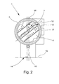
- Fig. 2
- eine Draufsicht auf das Messgerät der
Fig. 1 , - Fig. 3
- eine räumliche Darstellung eines Gehäuses eines Messgerätes,
- Fig. 4
- eine räumliche Darstellung eines Messgerätes und
- Fig. 5
- eine räumliche Darstellung einer weiteren Variante des Gehäuses eines Messgerätes.
- Fig. 1
- a schematic, essentially the basic arrangement clarifying representation of a part of a measuring device in section,
- Fig. 2
- a plan view of the measuring device of
Fig. 1 . - Fig. 3
- a spatial representation of a housing of a measuring device,
- Fig. 4
- a spatial representation of a measuring device and
- Fig. 5
- a spatial representation of another variant of the housing of a measuring device.
In der
In der
Zwischen den zwei Elektronikeinrichtungen 3, 4 ist das Kontaktierungselement 5 angeordnet, dass in sich gekapselt und insbesondere separat von den zwei Elektronikeinrichtungen 3, 4 ausgestaltet ist. Das Kontaktierungselement 5 dient dabei der elektrischen Verbindung zwischen den Elektronikeinrichtungen 3, 4 und auch der Trennung beider Elektronikeinrichtungen 3, 4, beispielsweise für die Gewährleistung der Eigensicherheit.Between the two
Für die Verbindung sind Übertragungselemente 6 vorgesehen, die hier in beide Richtungen als Stifte realisiert sind. Die Übertragungselemente 6 sind dabei innerhalb der Außenwandung 7, die hier aus Edelstahl besteht, des Kontaktierungselements 5 vergossen bzw. eingeglast, wobei für den Eigenschutz auf die erforderlichen Abstände zwischen den einzelnen Übertragungselementen 6 geachtet ist. In einer alternativen Ausgestaltung besteht die Außenwandung 7 aus einem Kunststoff bzw. aus einem Verbundwerkstoff. In der hier gezeigten Ausführung ist das Kontaktierungselement 5 stopfenförmig ausgestaltet.For the connection transmission elements 6 are provided, which are realized here as pins in both directions. The transmission elements 6 are encapsulated or glazed within the outer wall 7, which is made of stainless steel here, of the contacting
Der Innenraum des Gehäuses 2 ist hier in zwei Kammern 8, 9 unterteilt, in denen sich jeweils eine Elektronikeinheit 3, 4 befindet. Getrennt sind die zwei Kammern 8, 9 durch eine Wand, die einen Durchgang 10 aufweist, der das Kontaktierungselement 5 beherbergt. Vorliegend sind der Durchgang 10 und das Kontaktierungselement 5 derartig ausgestaltet und aufeinander abgestimmt, dass das Kontaktierungselement 5 passgenau im Durchgang 10 angeordnet ist.The interior of the
Am hier nach unten ragenden Hals des Gehäuses 2 wird insbesondere die jeweilige Sensoreinheit angebracht, z. B. durch eine Schraube fixiert. Durch die Anwendung von beispielsweise einem Bajonettverschluss kann jedoch auch eine Variante realisiert werden, in der die Sensoreinheit und das Gehäuse teilweise gegeneinander dreh- bzw. schwenkbar sind. Der untere Hals erlaubt beispielsweise auch das Einbringen von Kabeln oder z. B. flexiblen Leiterplatten, die von der - hier nicht dargestellten - Sensoreinheit ausgehen und die mit den Elektronikeinrichtungen 3, 4 zu verbinden sind.At here downwardly projecting neck of the
Bei einer Montage eines erfindungsgemäßen Messgerätes 1 werden die Elektronikeinrichtungen 3, 4 und das Kontaktierungselement 5 in das Gehäuse 2 eingebracht und ineinander gesteckt. Verbinden sich dabei insbesondere das Kontaktierungselement 5 und die jeweilige Elektronikeinrichtung 3, 4 spaltfrei miteinander, so ist durch die Verkapselung des Kontaktierungselements 5 kein weiterer Verguss wie im Stand der Technik erforderlich. Die Verbindung durch das Stecken ist insbesondere reversibel, so dass auch im eingebauten Zustand noch einzelne Komponenten beispielsweise ausgetauscht werden können.When mounting a
In der
Die
Von der ersten Längsachse und der zweiten Längsachse 15 wird eine Orientierungsebene 16 aufgespannt, die hier ebenfalls senkrecht zur Zeichnungsebene verläuft. Wie zu erkennen, ist die Platinenebene 18 in einem Winkel α = 45° gegenüber der Orientierungsebene 16 geneigt. Dabei sind jedoch auch andere Winkel α, in anderen hier nicht dargestellten Ausgestaltungen realisiert. Gemein ist allen Varianten, dass der Winkel α, sich von einem ganzzahligen Vielfachen von 90° unterscheidet, d. h. die Platinenebene 18 ist weder parallel zur Orientierungsebene 16 noch senkrecht dazu angeordnet. Die Platine 17 ist weiterhin auch in einem 45°-Winkel zur Anschlussebene 19 angeordnet. Auch bei dieser relativen Orientierung der Platine 17 oder Leiterplatte zur Anschlussebene 19 sind andere Winkel möglich, die jeweils zu einer Schräglage der Platine 17 führen. Diese Neigung gegenüber der Anschlussebene 19, über die zumeist die Anbringung des Messgerätes 1 an einem Behälter oder einem Rohr erfolgt, werden die Auswirkungen von Erschütterungen auf die Platine 17 bzw. deren Bauteile oder der Kontaktierungen der Bauteile reduziert.Of the first longitudinal axis and the second
In der dargestellten Variante ist weiterhin zu erkennen, dass das Gehäuse 2 noch drei weitere seitliche Zugänge beispielsweise für Kabelverbindungen aufweist.In the illustrated variant, it can further be seen that the
Die
Das Messgerät 1 der
Das Gehäuse 2 ist in der gezeigten Variante mit einem Deckel verschlossen, durch den hindurch ein Anzeige- und Bedienelement zu sehen ist. Für die Bedienung sind beispielsweise mechanische Tasten mit einer speziellen Folie vorgesehen. Alternativ lässt sich jedoch auch eine kapazitive oder induktive Tastatur realisieren, die auf die Näherung eines Fingers oder eines Stiftes reagiert. In einer weiteren Variante sind Hallsensoren im Gehäuse 2 vorgesehen, die mittels Magnetstiften durch einen geschlossenen Deckel bedient werden können und dadurch auch der Explosionsschutzanforderung entsprechen. Werden zwischen einem Display-Modul und der dahinterliegenden Elektroneinrichtung Kontaktstifte verwendet, so ist auch das Befestigen des Display-Moduls vereinfacht und es kann ggf. auch ein Drehen der Anzeigeeinheit gegenüber dem Gehäuse 2 einfach umgesetzt werden, indem beispielsweise die Anzahl der Kontaktstifte erhöht und die Kontaktstifte unter unterschiedlichen Raumwinkeln redundant ausgeführt werden. Dabei können bei der Anzeigeeinheit bzw. der zugeordneten Elektronikeinheit auch Stifte oder Buchsen variiert werden. Alternativ erfolgt die Kontaktierung über Kabel, so dass lediglich die Lagerung der Anzeige- bzw. Bedieneinheit unterschiedliche relative Einstellung erlauben muss.The
Im Gehäuse 2 des Messgeräts 1 der
Claims (10)
dadurch gekennzeichnet,
dass mindestens ein verkapseltes Kontaktierungselement (5) vorgesehen ist, dass das Kontaktierungselement (5) von den Elektronikeinrichtungen (3, 4) und dem Gehäuse (2) separat ausgestaltet ist, dass das Kontaktierungselement (5) zwischen den zwei Elektronikeinrichtungen (3, 4) angeordnet ist, und dass das Kontaktierungselement (5) mindestens ein elektronisches Übertragungselement (6) zur Erzeugung einer elektrischen Verbindung zwischen den zwei Elektronikeinrichtungen (3, 4) aufweist.Measuring device (1), with at least one housing (2) and with at least two electronic devices (3, 4),
characterized,
in that at least one encapsulated contacting element (5) is provided, that the contacting element (5) is configured separately from the electronic devices (3, 4) and the housing (2), that the contacting element (5) is arranged between the two electronic devices (3, 4). is arranged, and that the contacting element (5) at least one electronic transmission element (6) for generating an electrical connection between the two electronic devices (3, 4).
Applications Claiming Priority (1)
| Application Number | Priority Date | Filing Date | Title |
|---|---|---|---|
| DE102012005637.0A DE102012005637B4 (en) | 2012-03-22 | 2012-03-22 | gauge |
Publications (3)
| Publication Number | Publication Date |
|---|---|
| EP2642255A2 true EP2642255A2 (en) | 2013-09-25 |
| EP2642255A3 EP2642255A3 (en) | 2016-08-03 |
| EP2642255B1 EP2642255B1 (en) | 2023-06-14 |
Family
ID=47845837
Family Applications (1)
| Application Number | Title | Priority Date | Filing Date |
|---|---|---|---|
| EP13158799.0A Active EP2642255B1 (en) | 2012-03-22 | 2013-03-12 | Measuring apparatus |
Country Status (8)
| Country | Link |
|---|---|
| US (1) | US9030190B2 (en) |
| EP (1) | EP2642255B1 (en) |
| JP (1) | JP6335431B2 (en) |
| KR (1) | KR101998708B1 (en) |
| CN (1) | CN103411636B (en) |
| BR (1) | BR102013006714B1 (en) |
| CA (1) | CA2810864C (en) |
| DE (1) | DE102012005637B4 (en) |
Cited By (4)
| Publication number | Priority date | Publication date | Assignee | Title |
|---|---|---|---|---|
| EP3326269A4 (en) * | 2015-06-01 | 2018-10-10 | Prime Datum Development Company, LLC | Line replaceable unit (lru) sensor systems for motors and other machines |
| WO2019046526A1 (en) | 2017-08-30 | 2019-03-07 | Nidec Motor Corporation | Instrinsically-safe, explosion-proof encoder |
| US10670433B2 (en) | 2015-12-21 | 2020-06-02 | Endress + Hauser Flowtec Ag | Housing for a field device |
| WO2021004754A1 (en) * | 2019-07-11 | 2021-01-14 | Endress+Hauser Flowtec Ag | Housing module and field device |
Families Citing this family (17)
| Publication number | Priority date | Publication date | Assignee | Title |
|---|---|---|---|---|
| DE102012108415A1 (en) * | 2012-09-10 | 2014-06-12 | Endress + Hauser Flowtec Ag | Interface between a sensor unit and an explosion-proof housing |
| US10663931B2 (en) | 2013-09-24 | 2020-05-26 | Rosemount Inc. | Process variable transmitter with dual compartment housing |
| US9642273B2 (en) * | 2013-09-25 | 2017-05-02 | Rosemount Inc. | Industrial process field device with humidity-sealed electronics module |
| CN115014412A (en) | 2013-09-30 | 2022-09-06 | 罗斯蒙特公司 | Process variable transmitter with dual compartment housing |
| JP6135936B2 (en) * | 2014-06-11 | 2017-05-31 | 横河電機株式会社 | converter |
| DE102014111805B4 (en) | 2014-08-19 | 2023-07-20 | Krohne Messtechnik Gmbh | Device for determining a measured variable |
| US10369642B2 (en) * | 2015-03-12 | 2019-08-06 | Robert Bosch Tool Corporation | Power tool with protected circuit board orientation |
| US10015899B2 (en) | 2015-06-29 | 2018-07-03 | Rosemount Inc. | Terminal block with sealed interconnect system |
| GB2535556B (en) * | 2015-07-14 | 2017-06-28 | Longvale Ltd | Electrical Process Control Sensor Assemblies |
| EP3176547B1 (en) * | 2015-12-02 | 2018-09-19 | Siemens Aktiengesellschaft | Housing part for a measurement device having a microwave-permeable glass or ceramic window |
| DE102016104739A1 (en) * | 2016-03-15 | 2017-09-21 | Endress + Hauser Flowtec Ag | Field device of measuring and automation technology |
| JP6483050B2 (en) * | 2016-06-02 | 2019-03-13 | 長野計器株式会社 | Physical quantity measuring device |
| DE102018002977A1 (en) * | 2017-05-11 | 2018-11-15 | Wika Alexander Wiegand Se & Co. Kg | gauge |
| DE102017115259A1 (en) * | 2017-07-07 | 2019-01-10 | Krohne Messtechnik Gmbh | Measuring device and method for producing a measuring device |
| DE102017115260A1 (en) * | 2017-07-07 | 2019-01-10 | Krohne Messtechnik Gmbh | Measuring device and method for producing a measuring device |
| US11894643B2 (en) | 2021-05-12 | 2024-02-06 | E.J. Brooks Company | Meter block adaptor and method |
| USD1008832S1 (en) * | 2021-06-10 | 2023-12-26 | E.J. Brooks Company | Meter block adaptor |
Citations (17)
| Publication number | Priority date | Publication date | Assignee | Title |
|---|---|---|---|---|
| US3462539A (en) | 1966-07-15 | 1969-08-19 | Jerrold Electronics Corp | Ground bushing |
| DE4109475A1 (en) | 1991-03-22 | 1992-09-24 | Bosch Gmbh Robert | DISPLAY ARRANGIBLY ARRANGED ON A WALL OF A DEVICE HOUSE |
| EP0775292B1 (en) | 1994-08-11 | 2001-12-19 | Rosemount Inc. | Transmitter with moisture draining housing and improved method of mounting rfi filters |
| DE10126654A1 (en) | 2001-06-01 | 2002-12-05 | Endress & Hauser Gmbh & Co Kg | Housing for electronic device, has electronic unit in interior, display module for optional insertion in either of two openings, and connection module in other opening |
| DE20314618U1 (en) | 2003-09-19 | 2003-11-20 | Endress & Hauser Gmbh & Co Kg | Current and signal lead through for two chambers of instrument for measuring physical properties of fluid has cast insulating mass holding array of electrical conductors |
| DE10233296A1 (en) | 2002-07-22 | 2004-02-12 | Endress + Hauser Gmbh + Co. Kg | Method for producing a housing for an encapsulated sensor and corresponding housing |
| DE10327013A1 (en) | 2003-06-12 | 2004-12-30 | Endress + Hauser Wetzer Gmbh + Co Kg | Plug-in coupling system for detachable connection between programmable field device and field bus or programming device, has measurement sensor and transmitter |
| DE102004044890A1 (en) | 2004-09-14 | 2006-03-30 | Endress + Hauser Gmbh + Co. Kg | Device for determining and / or monitoring at least one process variable of a medium |
| DE19782057B4 (en) | 1996-10-04 | 2006-10-26 | Rosemount Inc., Eden Prairie | Process control transmitter with electrical feedthrough assembly |
| DE102005024259A1 (en) | 2005-05-27 | 2006-11-30 | Continental Aktiengesellschaft | Arrangement for fixing an electronic component or a battery on the inside of a pneumatic vehicle tire |
| DE102006009827A1 (en) | 2006-03-01 | 2007-09-06 | KROHNE Meßtechnik GmbH & Co. KG | Non-intrinsically powered meter |
| DE102007036484B3 (en) | 2007-08-01 | 2009-02-05 | Endress + Hauser Wetzer Gmbh + Co. Kg | Device for determining and / or monitoring the temperature |
| DE202010007043U1 (en) | 2010-04-15 | 2010-09-30 | Micro-Epsilon Messtechnik Gmbh & Co. Kg | sensor |
| DE102009054649A1 (en) | 2009-12-15 | 2011-06-16 | Endress + Hauser Wetzer Gmbh + Co. Kg | Modular transmitter |
| DE102010003743A1 (en) | 2010-04-08 | 2011-10-13 | Endress + Hauser Wetzer Gmbh + Co Kg | Housing for holding e.g. measuring-and/or operating electronic units of measuring device that is utilized for measuring parameter in safety-relevant applications, has lead-sealing strand indicating removal of connector to operator |
| WO2011160949A1 (en) | 2010-06-21 | 2011-12-29 | Endress+Hauser Flowtec Ag | Electronics housing for an electronic device and device formed therewith |
| DE102010033470A1 (en) | 2010-08-05 | 2012-02-09 | Krohne Messtechnik Gmbh | Control panel for a measuring device |
Family Cites Families (30)
| Publication number | Priority date | Publication date | Assignee | Title |
|---|---|---|---|---|
| DE1944198B2 (en) | 1969-08-30 | 1974-01-10 | Licentia Patent-Verwaltungs-Gmbh, 6000 Frankfurt | Electrical device or device |
| DE2530157A1 (en) | 1975-07-05 | 1977-02-03 | Bosch Gmbh Robert | ELECTRONIC CONTROL UNIT |
| JPS5992720U (en) * | 1982-12-14 | 1984-06-23 | 新明和工業株式会社 | road cleaning vehicle |
| US4465743A (en) * | 1982-12-15 | 1984-08-14 | Medtronic, Inc. | Electrochemical cells having lithium tetrachloroiodate cathodes |
| JPS618824U (en) * | 1984-06-21 | 1986-01-20 | 株式会社 金門製作所 | gas meter |
| JPS6212081A (en) * | 1985-07-10 | 1987-01-21 | 株式会社 明王化成 | Pin connector and manufacture thereof |
| JP3691057B2 (en) | 1993-06-26 | 2005-08-31 | ローベルト ボツシユ ゲゼルシヤフト ミツト ベシユレンクテル ハフツング | Mounting control device |
| CN1155329A (en) * | 1994-08-11 | 1997-07-23 | 罗斯蒙德公司 | Transmitter with water draining housing and improved method of mounting RFI filter |
| DE19733353C1 (en) * | 1997-08-01 | 1998-12-10 | Nico Pyrotechnik | Ignition unit for a personal protection device in a motor vehicle |
| US6109979A (en) * | 1997-10-31 | 2000-08-29 | Micro Motion, Inc. | Explosion proof feedthrough connector |
| DK0945714T3 (en) | 1998-03-17 | 2011-01-31 | Endress & Hauser Deutschland Ag & Co Kg | Electronic equipment for use in explosion-prone areas |
| US6508131B2 (en) | 1999-05-14 | 2003-01-21 | Rosemount Inc. | Process sensor module having a single ungrounded input/output conductor |
| US6556447B2 (en) | 2000-03-01 | 2003-04-29 | Endress + Hauser Flowtec Ag | Electronic apparatus with an enclosure |
| EP1130363A1 (en) * | 2000-03-01 | 2001-09-05 | Endress + Hauser Flowtec AG | Electronic apparatus with a housing |
| US6778389B1 (en) | 2003-07-03 | 2004-08-17 | Visteon Global Technologies, Inc. | Microelectronic package with tubular housing |
| DE202005017626U1 (en) | 2005-11-09 | 2006-01-05 | Aktiv-Sensor Gmbh | Pressure sensor unit with optional intelligence includes pressure injection molded casing with conductive tracks, molded interconnect device support surface and sensor opening |
| DE202006012815U1 (en) | 2006-08-17 | 2007-12-20 | Mts Sensor Technologie Gmbh & Co. Kg | travel length |
| US7816772B2 (en) | 2007-03-29 | 2010-10-19 | Allegro Microsystems, Inc. | Methods and apparatus for multi-stage molding of integrated circuit package |
| DE202007006794U1 (en) | 2007-05-11 | 2007-08-02 | Bürkert Werke GmbH & Co. KG | Connecting device for connecting a measuring cell to an evaluation |
| EP2232646B1 (en) | 2007-12-28 | 2014-05-21 | Emerson Electric Co. | Hermetic feed-through with hybrid seal structure |
| US8773864B2 (en) | 2008-06-18 | 2014-07-08 | Lockheed Martin Corporation | Enclosure assembly housing at least one electronic board assembly and systems using same |
| DE102008056817A1 (en) * | 2008-10-10 | 2010-04-15 | KROHNE Meßtechnik GmbH & Co. KG | Housing for an electrical or electronic device |
| DE202009011951U1 (en) | 2009-09-03 | 2011-01-20 | Pepperl + Fuchs Gmbh | Housing for a coil or a coil system of a sensor, such as inductive or capacitive proximity switch |
| US8487187B2 (en) * | 2009-09-09 | 2013-07-16 | Emerson Electric Co. | Solid core glass bead seal with stiffening rib |
| DE202009013919U1 (en) | 2009-10-14 | 2010-06-24 | Keller AG für Druckmeßtechnik | pressure transmitters |
| DE102009060872A1 (en) * | 2009-12-30 | 2011-08-18 | Baumer Innotec Ag | Sensor with housing and method for its manufacture |
| JP2011146436A (en) * | 2010-01-12 | 2011-07-28 | Yamatake Corp | Method of assembling electronic apparatus substrate and electronic apparatus |
| DE102011004914A1 (en) | 2011-03-01 | 2012-09-06 | Ifm Electronic Gmbh | Sensor e.g. hall sensor used in e.g. medical application, has sensor unit that is mounted in groove provided in connector in which stopper is mounted, such that O-ring groove, O-ring seal and stop are mounted at sides of stopper |
| DE102012212312A1 (en) | 2011-07-14 | 2013-01-17 | Hirschmann Automotive Gmbh | Linear path and angle sensor systems in leadframe design |
| DE102012005638C5 (en) | 2012-03-22 | 2018-03-29 | Krohne Messtechnik Gmbh | gauge |
-
2012
- 2012-03-22 DE DE102012005637.0A patent/DE102012005637B4/en active Active
- 2012-10-08 US US13/646,982 patent/US9030190B2/en active Active
-
2013
- 2013-03-12 EP EP13158799.0A patent/EP2642255B1/en active Active
- 2013-03-22 CA CA2810864A patent/CA2810864C/en active Active
- 2013-03-22 JP JP2013060657A patent/JP6335431B2/en active Active
- 2013-03-22 KR KR1020130030802A patent/KR101998708B1/en active IP Right Grant
- 2013-03-22 CN CN201310343705.9A patent/CN103411636B/en active Active
- 2013-03-22 BR BR102013006714-8A patent/BR102013006714B1/en active IP Right Grant
Patent Citations (17)
| Publication number | Priority date | Publication date | Assignee | Title |
|---|---|---|---|---|
| US3462539A (en) | 1966-07-15 | 1969-08-19 | Jerrold Electronics Corp | Ground bushing |
| DE4109475A1 (en) | 1991-03-22 | 1992-09-24 | Bosch Gmbh Robert | DISPLAY ARRANGIBLY ARRANGED ON A WALL OF A DEVICE HOUSE |
| EP0775292B1 (en) | 1994-08-11 | 2001-12-19 | Rosemount Inc. | Transmitter with moisture draining housing and improved method of mounting rfi filters |
| DE19782057B4 (en) | 1996-10-04 | 2006-10-26 | Rosemount Inc., Eden Prairie | Process control transmitter with electrical feedthrough assembly |
| DE10126654A1 (en) | 2001-06-01 | 2002-12-05 | Endress & Hauser Gmbh & Co Kg | Housing for electronic device, has electronic unit in interior, display module for optional insertion in either of two openings, and connection module in other opening |
| DE10233296A1 (en) | 2002-07-22 | 2004-02-12 | Endress + Hauser Gmbh + Co. Kg | Method for producing a housing for an encapsulated sensor and corresponding housing |
| DE10327013A1 (en) | 2003-06-12 | 2004-12-30 | Endress + Hauser Wetzer Gmbh + Co Kg | Plug-in coupling system for detachable connection between programmable field device and field bus or programming device, has measurement sensor and transmitter |
| DE20314618U1 (en) | 2003-09-19 | 2003-11-20 | Endress & Hauser Gmbh & Co Kg | Current and signal lead through for two chambers of instrument for measuring physical properties of fluid has cast insulating mass holding array of electrical conductors |
| DE102004044890A1 (en) | 2004-09-14 | 2006-03-30 | Endress + Hauser Gmbh + Co. Kg | Device for determining and / or monitoring at least one process variable of a medium |
| DE102005024259A1 (en) | 2005-05-27 | 2006-11-30 | Continental Aktiengesellschaft | Arrangement for fixing an electronic component or a battery on the inside of a pneumatic vehicle tire |
| DE102006009827A1 (en) | 2006-03-01 | 2007-09-06 | KROHNE Meßtechnik GmbH & Co. KG | Non-intrinsically powered meter |
| DE102007036484B3 (en) | 2007-08-01 | 2009-02-05 | Endress + Hauser Wetzer Gmbh + Co. Kg | Device for determining and / or monitoring the temperature |
| DE102009054649A1 (en) | 2009-12-15 | 2011-06-16 | Endress + Hauser Wetzer Gmbh + Co. Kg | Modular transmitter |
| DE102010003743A1 (en) | 2010-04-08 | 2011-10-13 | Endress + Hauser Wetzer Gmbh + Co Kg | Housing for holding e.g. measuring-and/or operating electronic units of measuring device that is utilized for measuring parameter in safety-relevant applications, has lead-sealing strand indicating removal of connector to operator |
| DE202010007043U1 (en) | 2010-04-15 | 2010-09-30 | Micro-Epsilon Messtechnik Gmbh & Co. Kg | sensor |
| WO2011160949A1 (en) | 2010-06-21 | 2011-12-29 | Endress+Hauser Flowtec Ag | Electronics housing for an electronic device and device formed therewith |
| DE102010033470A1 (en) | 2010-08-05 | 2012-02-09 | Krohne Messtechnik Gmbh | Control panel for a measuring device |
Cited By (6)
| Publication number | Priority date | Publication date | Assignee | Title |
|---|---|---|---|---|
| EP3326269A4 (en) * | 2015-06-01 | 2018-10-10 | Prime Datum Development Company, LLC | Line replaceable unit (lru) sensor systems for motors and other machines |
| US10804770B2 (en) | 2015-06-01 | 2020-10-13 | Prime Datum Development Company, Llc | Line replaceable unit (LRU) sensor systems for motors and other machines |
| US10670433B2 (en) | 2015-12-21 | 2020-06-02 | Endress + Hauser Flowtec Ag | Housing for a field device |
| WO2019046526A1 (en) | 2017-08-30 | 2019-03-07 | Nidec Motor Corporation | Instrinsically-safe, explosion-proof encoder |
| EP3676916A4 (en) * | 2017-08-30 | 2021-04-28 | Nidec Motor Corporation | Instrinsically-safe, explosion-proof encoder |
| WO2021004754A1 (en) * | 2019-07-11 | 2021-01-14 | Endress+Hauser Flowtec Ag | Housing module and field device |
Also Published As
| Publication number | Publication date |
|---|---|
| JP6335431B2 (en) | 2018-05-30 |
| EP2642255B1 (en) | 2023-06-14 |
| US20130249534A1 (en) | 2013-09-26 |
| EP2642255A3 (en) | 2016-08-03 |
| CA2810864A1 (en) | 2013-09-22 |
| CN103411636B (en) | 2017-04-12 |
| KR20130108179A (en) | 2013-10-02 |
| BR102013006714A2 (en) | 2015-06-23 |
| BR102013006714B1 (en) | 2020-11-24 |
| DE102012005637B4 (en) | 2019-02-21 |
| CA2810864C (en) | 2017-10-10 |
| CN103411636A (en) | 2013-11-27 |
| JP2013195434A (en) | 2013-09-30 |
| DE102012005637A1 (en) | 2013-09-26 |
| KR101998708B1 (en) | 2019-07-10 |
| US9030190B2 (en) | 2015-05-12 |
Similar Documents
| Publication | Publication Date | Title |
|---|---|---|
| DE102012005637B4 (en) | gauge | |
| EP2893299B1 (en) | Interface between a sensor unit and an explosion-proof housing | |
| DE112013000659B4 (en) | Energy conversion device | |
| DE202006016545U1 (en) | Electrical connection arrangement for switchboard, has plug part connected with shielding sheet metal having cable connection tongue that is bent or runs opposite to middle longitudinal axis and/or plane of mounting plate in inclined manner | |
| EP3091624A1 (en) | Installation socket for electric appliances | |
| WO2018114196A1 (en) | Connecting element, transmitter housing having connecting element inserted therein, and method for producing said connecting element | |
| EP3186862A1 (en) | Automation module for building automation | |
| EP3163258A1 (en) | Sensor unit | |
| DE102012014519B3 (en) | Dispatcher box e.g. sensor actuator box has annular connecting element which is provided to electrically-conductive contact foot portion of sleeve with metallic surface on underside of circuit board | |
| DE102012005638A1 (en) | gauge | |
| DE10219880B4 (en) | rotation sensor | |
| DE10256374B3 (en) | Contact device for connecting multi-wire cable conductors with sensor-actuator distributor having contact carrier fitted with contact element and separate contact guide body | |
| EP1320290A2 (en) | Distribution box | |
| EP3479073A1 (en) | Transducer for high-voltage measuring technology | |
| DE102012012528A1 (en) | Measuring device for determining a process variable | |
| DE102013002852B4 (en) | Distribution | |
| EP3164919B1 (en) | Cable termination for connecting a switchgear assembly to a high-voltage cable | |
| DE102006047474B4 (en) | Pressure gauge for process measurement | |
| EP2047484B1 (en) | Connecting piece for fitting to a fuse housing | |
| DE102005005252B4 (en) | contactor | |
| EP1173910B1 (en) | Mounting adapter for control or signalling devices | |
| DE102008061908B3 (en) | Socket outlet distributor for modular system, has box-shaped distribution housing, which has inject connector or inlet and integrated socket outlet, which is electrically connected to inject connector or inlet | |
| DE102006028144A1 (en) | Cable grommet for conducting cable through wall of e.g. electrical cabinet, has plate for receiving coaxial cable and sealing wall opening, where outer conductor of cable is electro-conductively connected with halves of discharge plate | |
| DE102008022742A1 (en) | Pressure tight feeding arrangement for electrical lines for e.g. sensor, has stack of set of printed circuit boards that are arranged parallel to wall, and set of electrical lines fed through connection lines in printed circuit boards | |
| EP4135168A1 (en) | Electric interface device for an electric motor |
Legal Events
| Date | Code | Title | Description |
|---|---|---|---|
| PUAI | Public reference made under article 153(3) epc to a published international application that has entered the european phase |
Free format text: ORIGINAL CODE: 0009012 |
|
| AK | Designated contracting states |
Kind code of ref document: A2 Designated state(s): AL AT BE BG CH CY CZ DE DK EE ES FI FR GB GR HR HU IE IS IT LI LT LU LV MC MK MT NL NO PL PT RO RS SE SI SK SM TR |
|
| AX | Request for extension of the european patent |
Extension state: BA ME |
|
| PUAL | Search report despatched |
Free format text: ORIGINAL CODE: 0009013 |
|
| AK | Designated contracting states |
Kind code of ref document: A3 Designated state(s): AL AT BE BG CH CY CZ DE DK EE ES FI FR GB GR HR HU IE IS IT LI LT LU LV MC MK MT NL NO PL PT RO RS SE SI SK SM TR |
|
| AX | Request for extension of the european patent |
Extension state: BA ME |
|
| RIC1 | Information provided on ipc code assigned before grant |
Ipc: G01D 11/24 20060101AFI20160630BHEP |
|
| STAA | Information on the status of an ep patent application or granted ep patent |
Free format text: STATUS: REQUEST FOR EXAMINATION WAS MADE |
|
| 17P | Request for examination filed |
Effective date: 20170203 |
|
| RBV | Designated contracting states (corrected) |
Designated state(s): AL AT BE BG CH CY CZ DE DK EE ES FI FR GB GR HR HU IE IS IT LI LT LU LV MC MK MT NL NO PL PT RO RS SE SI SK SM TR |
|
| GRAP | Despatch of communication of intention to grant a patent |
Free format text: ORIGINAL CODE: EPIDOSNIGR1 |
|
| STAA | Information on the status of an ep patent application or granted ep patent |
Free format text: STATUS: GRANT OF PATENT IS INTENDED |
|
| TPAC | Observations filed by third parties |
Free format text: ORIGINAL CODE: EPIDOSNTIPA |
|
| GRAS | Grant fee paid |
Free format text: ORIGINAL CODE: EPIDOSNIGR3 |
|
| INTG | Intention to grant announced |
Effective date: 20180219 |
|
| GRAJ | Information related to disapproval of communication of intention to grant by the applicant or resumption of examination proceedings by the epo deleted |
Free format text: ORIGINAL CODE: EPIDOSDIGR1 |
|
| GRAL | Information related to payment of fee for publishing/printing deleted |
Free format text: ORIGINAL CODE: EPIDOSDIGR3 |
|
| STAA | Information on the status of an ep patent application or granted ep patent |
Free format text: STATUS: REQUEST FOR EXAMINATION WAS MADE |
|
| GRAP | Despatch of communication of intention to grant a patent |
Free format text: ORIGINAL CODE: EPIDOSNIGR1 |
|
| STAA | Information on the status of an ep patent application or granted ep patent |
Free format text: STATUS: GRANT OF PATENT IS INTENDED |
|
| INTC | Intention to grant announced (deleted) | ||
| INTG | Intention to grant announced |
Effective date: 20180824 |
|
| TPAC | Observations filed by third parties |
Free format text: ORIGINAL CODE: EPIDOSNTIPA |
|
| 17Q | First examination report despatched |
Effective date: 20181012 |
|
| GRAJ | Information related to disapproval of communication of intention to grant by the applicant or resumption of examination proceedings by the epo deleted |
Free format text: ORIGINAL CODE: EPIDOSDIGR1 |
|
| GRAL | Information related to payment of fee for publishing/printing deleted |
Free format text: ORIGINAL CODE: EPIDOSDIGR3 |
|
| STAA | Information on the status of an ep patent application or granted ep patent |
Free format text: STATUS: EXAMINATION IS IN PROGRESS |
|
| INTC | Intention to grant announced (deleted) | ||
| GRAP | Despatch of communication of intention to grant a patent |
Free format text: ORIGINAL CODE: EPIDOSNIGR1 |
|
| STAA | Information on the status of an ep patent application or granted ep patent |
Free format text: STATUS: GRANT OF PATENT IS INTENDED |
|
| TPAC | Observations filed by third parties |
Free format text: ORIGINAL CODE: EPIDOSNTIPA |
|
| GRAJ | Information related to disapproval of communication of intention to grant by the applicant or resumption of examination proceedings by the epo deleted |
Free format text: ORIGINAL CODE: EPIDOSDIGR1 |
|
| GRAL | Information related to payment of fee for publishing/printing deleted |
Free format text: ORIGINAL CODE: EPIDOSDIGR3 |
|
| STAA | Information on the status of an ep patent application or granted ep patent |
Free format text: STATUS: EXAMINATION IS IN PROGRESS |
|
| INTG | Intention to grant announced |
Effective date: 20191017 |
|
| INTC | Intention to grant announced (deleted) | ||
| STAA | Information on the status of an ep patent application or granted ep patent |
Free format text: STATUS: EXAMINATION IS IN PROGRESS |
|
| STAA | Information on the status of an ep patent application or granted ep patent |
Free format text: STATUS: EXAMINATION IS IN PROGRESS |
|
| GRAP | Despatch of communication of intention to grant a patent |
Free format text: ORIGINAL CODE: EPIDOSNIGR1 |
|
| STAA | Information on the status of an ep patent application or granted ep patent |
Free format text: STATUS: GRANT OF PATENT IS INTENDED |
|
| INTG | Intention to grant announced |
Effective date: 20230125 |
|
| GRAS | Grant fee paid |
Free format text: ORIGINAL CODE: EPIDOSNIGR3 |
|
| GRAA | (expected) grant |
Free format text: ORIGINAL CODE: 0009210 |
|
| STAA | Information on the status of an ep patent application or granted ep patent |
Free format text: STATUS: THE PATENT HAS BEEN GRANTED |
|
| AK | Designated contracting states |
Kind code of ref document: B1 Designated state(s): AL AT BE BG CH CY CZ DE DK EE ES FI FR GB GR HR HU IE IS IT LI LT LU LV MC MK MT NL NO PL PT RO RS SE SI SK SM TR |
|
| REG | Reference to a national code |
Ref country code: GB Ref legal event code: FG4D Free format text: NOT ENGLISH |
|
| REG | Reference to a national code |
Ref country code: CH Ref legal event code: EP |
|
| REG | Reference to a national code |
Ref country code: DE Ref legal event code: R096 Ref document number: 502013016409 Country of ref document: DE |
|
| REG | Reference to a national code |
Ref country code: AT Ref legal event code: REF Ref document number: 1579528 Country of ref document: AT Kind code of ref document: T Effective date: 20230715 |
|
| P01 | Opt-out of the competence of the unified patent court (upc) registered |
Effective date: 20230816 |
|
| REG | Reference to a national code |
Ref country code: NL Ref legal event code: FP |
|
| REG | Reference to a national code |
Ref country code: LT Ref legal event code: MG9D |
|
| PG25 | Lapsed in a contracting state [announced via postgrant information from national office to epo] |
Ref country code: SE Free format text: LAPSE BECAUSE OF FAILURE TO SUBMIT A TRANSLATION OF THE DESCRIPTION OR TO PAY THE FEE WITHIN THE PRESCRIBED TIME-LIMIT Effective date: 20230614 Ref country code: NO Free format text: LAPSE BECAUSE OF FAILURE TO SUBMIT A TRANSLATION OF THE DESCRIPTION OR TO PAY THE FEE WITHIN THE PRESCRIBED TIME-LIMIT Effective date: 20230914 Ref country code: ES Free format text: LAPSE BECAUSE OF FAILURE TO SUBMIT A TRANSLATION OF THE DESCRIPTION OR TO PAY THE FEE WITHIN THE PRESCRIBED TIME-LIMIT Effective date: 20230614 |
|
| PG25 | Lapsed in a contracting state [announced via postgrant information from national office to epo] |
Ref country code: RS Free format text: LAPSE BECAUSE OF FAILURE TO SUBMIT A TRANSLATION OF THE DESCRIPTION OR TO PAY THE FEE WITHIN THE PRESCRIBED TIME-LIMIT Effective date: 20230614 Ref country code: LV Free format text: LAPSE BECAUSE OF FAILURE TO SUBMIT A TRANSLATION OF THE DESCRIPTION OR TO PAY THE FEE WITHIN THE PRESCRIBED TIME-LIMIT Effective date: 20230614 Ref country code: LT Free format text: LAPSE BECAUSE OF FAILURE TO SUBMIT A TRANSLATION OF THE DESCRIPTION OR TO PAY THE FEE WITHIN THE PRESCRIBED TIME-LIMIT Effective date: 20230614 Ref country code: HR Free format text: LAPSE BECAUSE OF FAILURE TO SUBMIT A TRANSLATION OF THE DESCRIPTION OR TO PAY THE FEE WITHIN THE PRESCRIBED TIME-LIMIT Effective date: 20230614 Ref country code: GR Free format text: LAPSE BECAUSE OF FAILURE TO SUBMIT A TRANSLATION OF THE DESCRIPTION OR TO PAY THE FEE WITHIN THE PRESCRIBED TIME-LIMIT Effective date: 20230915 |
|
| PG25 | Lapsed in a contracting state [announced via postgrant information from national office to epo] |
Ref country code: FI Free format text: LAPSE BECAUSE OF FAILURE TO SUBMIT A TRANSLATION OF THE DESCRIPTION OR TO PAY THE FEE WITHIN THE PRESCRIBED TIME-LIMIT Effective date: 20230614 |
|
| PG25 | Lapsed in a contracting state [announced via postgrant information from national office to epo] |
Ref country code: SK Free format text: LAPSE BECAUSE OF FAILURE TO SUBMIT A TRANSLATION OF THE DESCRIPTION OR TO PAY THE FEE WITHIN THE PRESCRIBED TIME-LIMIT Effective date: 20230614 |
|
| PG25 | Lapsed in a contracting state [announced via postgrant information from national office to epo] |
Ref country code: IS Free format text: LAPSE BECAUSE OF FAILURE TO SUBMIT A TRANSLATION OF THE DESCRIPTION OR TO PAY THE FEE WITHIN THE PRESCRIBED TIME-LIMIT Effective date: 20231014 |
|
| PG25 | Lapsed in a contracting state [announced via postgrant information from national office to epo] |
Ref country code: SM Free format text: LAPSE BECAUSE OF FAILURE TO SUBMIT A TRANSLATION OF THE DESCRIPTION OR TO PAY THE FEE WITHIN THE PRESCRIBED TIME-LIMIT Effective date: 20230614 Ref country code: SK Free format text: LAPSE BECAUSE OF FAILURE TO SUBMIT A TRANSLATION OF THE DESCRIPTION OR TO PAY THE FEE WITHIN THE PRESCRIBED TIME-LIMIT Effective date: 20230614 Ref country code: RO Free format text: LAPSE BECAUSE OF FAILURE TO SUBMIT A TRANSLATION OF THE DESCRIPTION OR TO PAY THE FEE WITHIN THE PRESCRIBED TIME-LIMIT Effective date: 20230614 Ref country code: PT Free format text: LAPSE BECAUSE OF FAILURE TO SUBMIT A TRANSLATION OF THE DESCRIPTION OR TO PAY THE FEE WITHIN THE PRESCRIBED TIME-LIMIT Effective date: 20231016 Ref country code: IS Free format text: LAPSE BECAUSE OF FAILURE TO SUBMIT A TRANSLATION OF THE DESCRIPTION OR TO PAY THE FEE WITHIN THE PRESCRIBED TIME-LIMIT Effective date: 20231014 Ref country code: EE Free format text: LAPSE BECAUSE OF FAILURE TO SUBMIT A TRANSLATION OF THE DESCRIPTION OR TO PAY THE FEE WITHIN THE PRESCRIBED TIME-LIMIT Effective date: 20230614 Ref country code: CZ Free format text: LAPSE BECAUSE OF FAILURE TO SUBMIT A TRANSLATION OF THE DESCRIPTION OR TO PAY THE FEE WITHIN THE PRESCRIBED TIME-LIMIT Effective date: 20230614 |
|
| PG25 | Lapsed in a contracting state [announced via postgrant information from national office to epo] |
Ref country code: PL Free format text: LAPSE BECAUSE OF FAILURE TO SUBMIT A TRANSLATION OF THE DESCRIPTION OR TO PAY THE FEE WITHIN THE PRESCRIBED TIME-LIMIT Effective date: 20230614 |
|
| REG | Reference to a national code |
Ref country code: DE Ref legal event code: R026 Ref document number: 502013016409 Country of ref document: DE |
|
| PLBI | Opposition filed |
Free format text: ORIGINAL CODE: 0009260 |
|
| PLAX | Notice of opposition and request to file observation + time limit sent |
Free format text: ORIGINAL CODE: EPIDOSNOBS2 |
|
| PGFP | Annual fee paid to national office [announced via postgrant information from national office to epo] |
Ref country code: NL Payment date: 20240320 Year of fee payment: 12 |
|
| 26 | Opposition filed |
Opponent name: ENDRESS+HAUSER GROUP SERVICES (DEUTSCHLAND) AG+CO. KG Effective date: 20240312 |