EP2642207B1 - Micromixer combustion head end assembly - Google Patents
Micromixer combustion head end assembly Download PDFInfo
- Publication number
- EP2642207B1 EP2642207B1 EP13159327.9A EP13159327A EP2642207B1 EP 2642207 B1 EP2642207 B1 EP 2642207B1 EP 13159327 A EP13159327 A EP 13159327A EP 2642207 B1 EP2642207 B1 EP 2642207B1
- Authority
- EP
- European Patent Office
- Prior art keywords
- micromixer
- fuel
- tubes
- air
- mixing tubes
- Prior art date
- Legal status (The legal status is an assumption and is not a legal conclusion. Google has not performed a legal analysis and makes no representation as to the accuracy of the status listed.)
- Active
Links
- 238000002485 combustion reaction Methods 0.000 title claims description 7
- 239000000446 fuel Substances 0.000 claims description 41
- 239000000203 mixture Substances 0.000 claims description 5
- 238000011144 upstream manufacturing Methods 0.000 claims description 4
- 230000003750 conditioning effect Effects 0.000 claims description 3
- 239000007789 gas Substances 0.000 description 16
- MWUXSHHQAYIFBG-UHFFFAOYSA-N nitrogen oxide Inorganic materials O=[N] MWUXSHHQAYIFBG-UHFFFAOYSA-N 0.000 description 15
- 239000000567 combustion gas Substances 0.000 description 5
- 238000010586 diagram Methods 0.000 description 4
- 239000007788 liquid Substances 0.000 description 3
- VNWKTOKETHGBQD-UHFFFAOYSA-N methane Chemical compound C VNWKTOKETHGBQD-UHFFFAOYSA-N 0.000 description 2
- 238000006243 chemical reaction Methods 0.000 description 1
- 230000003247 decreasing effect Effects 0.000 description 1
- 230000009977 dual effect Effects 0.000 description 1
- 238000012423 maintenance Methods 0.000 description 1
- 239000003345 natural gas Substances 0.000 description 1
- 238000010248 power generation Methods 0.000 description 1
- 239000007787 solid Substances 0.000 description 1
Images


Classifications
-
- F—MECHANICAL ENGINEERING; LIGHTING; HEATING; WEAPONS; BLASTING
- F23—COMBUSTION APPARATUS; COMBUSTION PROCESSES
- F23R—GENERATING COMBUSTION PRODUCTS OF HIGH PRESSURE OR HIGH VELOCITY, e.g. GAS-TURBINE COMBUSTION CHAMBERS
- F23R3/00—Continuous combustion chambers using liquid or gaseous fuel
- F23R3/28—Continuous combustion chambers using liquid or gaseous fuel characterised by the fuel supply
- F23R3/286—Continuous combustion chambers using liquid or gaseous fuel characterised by the fuel supply having fuel-air premixing devices
Definitions
- Embodiments of the present application relate generally to gas turbine engines and more particularly to micromixers.
- Gas turbine efficiency generally increases with the temperature of the combustion gas stream. Higher combustion gas stream temperatures, however, may produce higher levels of undesirable emissions such as nitrogen oxides (NOx) and the like. NOx emissions generally are subject to governmental regulations. Improved gas turbine efficiency therefore must be balanced with compliance with emissions regulations. Lower NOx emission levels may be achieved by providing for good mixing of the fuel stream and the air stream. For example, the fuel stream and the air stream may be premixed in a Dry Low NOx (DLN) combustor before being admitted to a reaction or a combustion zone. Such premixing tends to reduce combustion temperatures and NOx emissions output.
- DLN Dry Low NOx
- micromixer designs there may be multiple fuel feeds and/or liquid cartridge or blank feeds that obstruct air flow and decrease the mixing of fuel and air.
- current micromixers are generally supported by external walls that inhibit air flow to the head end of the micromixer. Examples of micromixers can be found in US 2012/031102 and US 2011/0016871 A1 , which discloses the features of the preamble of claim 1. There is a need for a micromixer that better facilitates fuel and air mixing.
- micromixer showing the features of claim 1.
- Illustrative embodiments are directed to, among other things, micro mixers for a combustor.
- Fig. 1 shows a schematic view of a gas turbine engine 10 as may be used herein.
- the gas turbine engine 10 may include a compressor 15.
- the compressor 15 compresses an incoming flow of air 20.
- the compressor 15 delivers the compressed flow of air 20 to a combustor 25.
- the combustor 25 mixes the compressed flow of air 20 with a pressurized flow of fuel 30 and ignites the mixture to create a flow of combustion gases 35.
- the gas turbine engine 10 may include any number of combustors 25.
- the flow of combustion gases 35 is in turn delivered to a turbine 40.
- the flow of combustion gases 35 drives the turbine 40 so as to produce mechanical work.
- the mechanical work produced in the turbine 40 drives the compressor 15 via a shaft 45 and an external load 50 such as an electrical generator and the like.
- the gas turbine engine 10 may use natural gas, various types of syngas, and/or other types of fuels.
- the gas turbine engine 10 may be any one of a number of different gas turbine engines offered by General Electric Company of Schenectady, New York, including, but not limited to, those such as a 7 or a 9 series heavy duty gas turbine engine and the like.
- the gas turbine engine 10 may have different configurations and may use other types of components.
- gas turbine engines also may be used herein.
- Multiple gas turbine engines, other types of turbines, and other types of power generation equipment also may be used herein together.
- Figs. 2 and 3 depict a component of the combustor 25 in Fig. 1 ; specifically, a micromixer 100 or a portion thereof.
- the micromixer 100 may include a base nozzle structure 102 in communication with a fuel plenum 104, an air intake 106, and numerous mixing tubes 108 forming one or more segmented mixing tube bundles.
- the base nozzle structure 102 supplies a fuel to the fuel plenum 104.
- the fuel exits the fuel plenum 104 and enters the mixing tubes 108.
- Air is directed into the mixing tubes 108 through the air intake 106 and mixes with the fuel to create an air/fuel mixture.
- the air/fuel mixture exits the mixing tubes 108 and enters into a downstream combustion chamber.
- the micromixer 100 may be segmented, meaning the micromixer 100 may include a number of base nozzle structures 102.
- each base nozzle structure 102 is associated with a bundle of mixing tubes 108 that are at least partially supported by the base nozzle structure 102.
- the base nozzle structures 102 may be attached to a combustor endplate 109.
- the micromixer 100 may include the base nozzle structure 102 having coaxial tubes including an inner tube 110 and an outer tube 112.
- the outer tube 112 of the coaxial tubes supplies a fuel to the mixing tubes 108.
- the inner tube 110 of the coaxial tubes supplies a liquid cartridge or blank to the combustion chamber.
- the inner tube 110 of the coaxial tube may include an igniter or flame detector.
- the inner tube 110 of the coaxial tubes may include a variety of combustor components.
- An air inlet 114 is disposed upstream of the mixing tubes 108 and supplies air to the mixing tubes 108.
- An air conditioner plate 116 is disposed upstream of the mixing tubes 108.
- the fuel supplied by the outer tube 112 of the coaxial tubes enters the fuel plenum 104 before entering the mixing tubes 108.
- the fuel entering the fuel plenum 104 is redirected 180 degrees (as indicated by the dashed arrows at the end of outer tube 112) before entering the mixing tubes 108 through one or more holes 118 in the mixing tubes 108.
- a fuel conditioning plate 120 is disposed within the fuel plenum 104.
- the air/fuel mixture exits the mixing tubes 108 (as indicated by the solid arrow within the mixing tubes 108) into the combustion chamber.
- the base nozzle structure 102 of the micromixer 100 provides both structural support and an outer tube 112 for the fuel to enter the fuel plenum 104.
- the fuel can be gas.
- the inner tube 110 may include a liquid cartridge (for dual fuel), a blank cartridge (for gas only), an igniter, a flame detector, or any other combustor component.
- the base nozzle structure 102 is attached to the inlet plate 116 of the micromixer assembly.
- the fuel is injected from the end cover 109 into the base nozzle structure 102 and flows through the annulus formed between inner tube 110 and the outer tube 112 into the fuel plenum 104.
- the fuel then enters the mixing tube holes 118 where it is mixed with head end air.
- the head end air flows through the flow conditioning plate 116 and into the mixing tube 108.
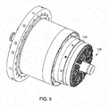
- the micromixer 100 may include an end cap assembly 140 disposed about each of the segmented mixing tube bundles 108.
- the end cap assembly 140 may include a cap face 141 having a number of apertures 143 for corresponding segmented mixing tube bundles 108 to pass through. Sidewalls 145 may extend about the circumference of the cap face to form a lip.
- the end cap assembly 140 may provide additional support to the segmented mixing tube bundles 108.
- the end cap assembly 140 may be removable from the segmented mixing tube bundles 108 such that during maintenance, the end cap assembly 140 may be removed and segmented mixing tube bundles 108 may be replaced and the end cap assembly 140 put back on.
- the end cap assembly 140 may be removeably attached to a support structure 146 encompassing the micromixer.
- the micromixer 100 may include one or more dampening mechanism 142 disposed about the micromixer 100.
- the dampening mechanism 142 may include one or more hula springs 144.
- the hula spring 144 may be disposed between a segmented portion of the micromixer 100 and an outer support structure 146 of the combustor.
- the hula spring 144 may dampen the vibration associated with the combustor and provide additional support to the micromixer assembly.
- the hula spring 144 may at least partially provide additional support to the segmented mixing tube bundles 108.
- a means may be provided to facilitate the turning of air within the micromixer.
- a baffle 148 may be disposed within the airflow path of the mixromixer 100.
- the support structure 146 encompassing the micromixer 100 may include flared portions 152.
- the present micromixer reduces the number of protrusions into the air flow path so as to facilitate a more uniform air feed in the mixing tubes.
- a technical advantage of the present micromixer includes a more uniform air feed to the mixing tubes. Another advantage of the present micromixer is that it facilitates fuel feed distribution to the mixing tubes and does not require a complex base nozzle structure to support the micromixer assembly. This results in a micromixer assembly that has lower NOx emissions because the air and fuel distribution are more uniform.
- the overall cost of the micromixer may be less and it may be more reliable because the number of welds is reduced, the number of parts is decreased, and the analytical assessment is more straightforward.
Applications Claiming Priority (1)
| Application Number | Priority Date | Filing Date | Title |
|---|---|---|---|
| US13/423,894 US9163839B2 (en) | 2012-03-19 | 2012-03-19 | Micromixer combustion head end assembly |
Publications (3)
| Publication Number | Publication Date |
|---|---|
| EP2642207A2 EP2642207A2 (en) | 2013-09-25 |
| EP2642207A3 EP2642207A3 (en) | 2018-03-21 |
| EP2642207B1 true EP2642207B1 (en) | 2021-07-07 |
Family
ID=47913020
Family Applications (1)
| Application Number | Title | Priority Date | Filing Date |
|---|---|---|---|
| EP13159327.9A Active EP2642207B1 (en) | 2012-03-19 | 2013-03-15 | Micromixer combustion head end assembly |
Country Status (5)
| Country | Link |
|---|---|
| US (1) | US9163839B2 (ja) |
| EP (1) | EP2642207B1 (ja) |
| JP (1) | JP6203510B2 (ja) |
| CN (1) | CN103322592B (ja) |
| RU (1) | RU2013111942A (ja) |
Families Citing this family (27)
| Publication number | Priority date | Publication date | Assignee | Title |
|---|---|---|---|---|
| US9151503B2 (en) | 2013-01-04 | 2015-10-06 | General Electric Company | Coaxial fuel supply for a micromixer |
| US9347668B2 (en) | 2013-03-12 | 2016-05-24 | General Electric Company | End cover configuration and assembly |
| US9671112B2 (en) | 2013-03-12 | 2017-06-06 | General Electric Company | Air diffuser for a head end of a combustor |
| US9366439B2 (en) | 2013-03-12 | 2016-06-14 | General Electric Company | Combustor end cover with fuel plenums |
| US9765973B2 (en) | 2013-03-12 | 2017-09-19 | General Electric Company | System and method for tube level air flow conditioning |
| US9759425B2 (en) * | 2013-03-12 | 2017-09-12 | General Electric Company | System and method having multi-tube fuel nozzle with multiple fuel injectors |
| US9528444B2 (en) | 2013-03-12 | 2016-12-27 | General Electric Company | System having multi-tube fuel nozzle with floating arrangement of mixing tubes |
| US9650959B2 (en) | 2013-03-12 | 2017-05-16 | General Electric Company | Fuel-air mixing system with mixing chambers of various lengths for gas turbine system |
| US9534787B2 (en) | 2013-03-12 | 2017-01-03 | General Electric Company | Micromixing cap assembly |
| US9651259B2 (en) | 2013-03-12 | 2017-05-16 | General Electric Company | Multi-injector micromixing system |
| US9546789B2 (en) * | 2013-03-15 | 2017-01-17 | General Electric Company | System having a multi-tube fuel nozzle |
| EP3059499B1 (en) | 2013-10-18 | 2019-04-10 | Mitsubishi Heavy Industries, Ltd. | Fuel injector |
| US9581335B2 (en) | 2014-08-07 | 2017-02-28 | General Electric Company | Fuel nozzle tube retention |
| US10094568B2 (en) | 2014-08-28 | 2018-10-09 | General Electric Company | Combustor dynamics mitigation |
| US10458655B2 (en) | 2015-06-30 | 2019-10-29 | General Electric Company | Fuel nozzle assembly |
| US10465909B2 (en) * | 2016-11-04 | 2019-11-05 | General Electric Company | Mini mixing fuel nozzle assembly with mixing sleeve |
| US11248529B2 (en) | 2016-12-13 | 2022-02-15 | General Electric Company | Methods for startup and operation of gas turbine combined cycle power plants using NMHC fuels |
| US11041625B2 (en) | 2016-12-16 | 2021-06-22 | General Electric Company | Fuel nozzle with narrow-band acoustic damper |
| US10344982B2 (en) | 2016-12-30 | 2019-07-09 | General Electric Company | Compact multi-residence time bundled tube fuel nozzle having transition portions of different lengths |
| US10571126B2 (en) | 2017-02-08 | 2020-02-25 | General Electric Company | Method to provide a braze coating with wear property on micromixer tubes |
| US10669942B2 (en) | 2017-02-23 | 2020-06-02 | General Electric Company | Endcover assembly for a combustor |
| US10690057B2 (en) * | 2017-04-25 | 2020-06-23 | General Electric Company | Turbomachine combustor end cover assembly with flame detector sight tube collinear with a tube of a bundled tube fuel nozzle |
| US10399046B1 (en) * | 2017-08-03 | 2019-09-03 | Komax, Inc. | Steam injection and mixing device |
| CN112856483B (zh) * | 2021-01-12 | 2022-07-15 | 哈尔滨工业大学 | 一种加湿微混燃烧器 |
| KR102415892B1 (ko) * | 2021-01-27 | 2022-06-30 | 두산에너빌리티 주식회사 | 마이크로 믹서 및 이를 포함하는 연소기 |
| JP2023104876A (ja) | 2022-01-18 | 2023-07-28 | ドゥサン エナービリティー カンパニー リミテッド | 燃焼器用ノズル、燃焼器およびこれを含むガスタービン |
| CN115405928B (zh) * | 2022-08-22 | 2024-04-19 | 哈尔滨工业大学 | 一种多通道微混燃烧器 |
Family Cites Families (28)
| Publication number | Priority date | Publication date | Assignee | Title |
|---|---|---|---|---|
| US4100733A (en) * | 1976-10-04 | 1978-07-18 | United Technologies Corporation | Premix combustor |
| US6598383B1 (en) * | 1999-12-08 | 2003-07-29 | General Electric Co. | Fuel system configuration and method for staging fuel for gas turbines utilizing both gaseous and liquid fuels |
| JP3962554B2 (ja) * | 2001-04-19 | 2007-08-22 | 三菱重工業株式会社 | ガスタービン燃焼器及びガスタービン |
| JP4610800B2 (ja) * | 2001-06-29 | 2011-01-12 | 三菱重工業株式会社 | ガスタービン燃焼器 |
| US20030101729A1 (en) * | 2001-12-05 | 2003-06-05 | Honeywell International, Inc. | Retrofittable air assisted fuel injection method to control gaseous and acoustic emissions |
| US8112999B2 (en) * | 2008-08-05 | 2012-02-14 | General Electric Company | Turbomachine injection nozzle including a coolant delivery system |
| US8215116B2 (en) * | 2008-10-02 | 2012-07-10 | General Electric Company | System and method for air-fuel mixing in gas turbines |
| US9140454B2 (en) | 2009-01-23 | 2015-09-22 | General Electric Company | Bundled multi-tube nozzle for a turbomachine |
| US8205452B2 (en) * | 2009-02-02 | 2012-06-26 | General Electric Company | Apparatus for fuel injection in a turbine engine |
| US8424311B2 (en) * | 2009-02-27 | 2013-04-23 | General Electric Company | Premixed direct injection disk |
| US8528336B2 (en) | 2009-03-30 | 2013-09-10 | General Electric Company | Fuel nozzle spring support for shifting a natural frequency |
| US8157189B2 (en) * | 2009-04-03 | 2012-04-17 | General Electric Company | Premixing direct injector |
| US8234872B2 (en) * | 2009-05-01 | 2012-08-07 | General Electric Company | Turbine air flow conditioner |
| US8607568B2 (en) * | 2009-05-14 | 2013-12-17 | General Electric Company | Dry low NOx combustion system with pre-mixed direct-injection secondary fuel nozzle |
| US20110016866A1 (en) * | 2009-07-22 | 2011-01-27 | General Electric Company | Apparatus for fuel injection in a turbine engine |
| US8616002B2 (en) * | 2009-07-23 | 2013-12-31 | General Electric Company | Gas turbine premixing systems |
| US8181891B2 (en) * | 2009-09-08 | 2012-05-22 | General Electric Company | Monolithic fuel injector and related manufacturing method |
| US8276385B2 (en) * | 2009-10-08 | 2012-10-02 | General Electric Company | Staged multi-tube premixing injector |
| US8683804B2 (en) * | 2009-11-13 | 2014-04-01 | General Electric Company | Premixing apparatus for fuel injection in a turbine engine |
| US20110209481A1 (en) * | 2010-02-26 | 2011-09-01 | General Electric Company | Turbine Combustor End Cover |
| US8590311B2 (en) * | 2010-04-28 | 2013-11-26 | General Electric Company | Pocketed air and fuel mixing tube |
| US8613197B2 (en) * | 2010-08-05 | 2013-12-24 | General Electric Company | Turbine combustor with fuel nozzles having inner and outer fuel circuits |
| US8511092B2 (en) * | 2010-08-13 | 2013-08-20 | General Electric Company | Dimpled/grooved face on a fuel injection nozzle body for flame stabilization and related method |
| US20120058437A1 (en) * | 2010-09-08 | 2012-03-08 | General Electric Company | Apparatus and method for mixing fuel in a gas turbine nozzle |
| US8800289B2 (en) * | 2010-09-08 | 2014-08-12 | General Electric Company | Apparatus and method for mixing fuel in a gas turbine nozzle |
| US8925324B2 (en) * | 2010-10-05 | 2015-01-06 | General Electric Company | Turbomachine including a mixing tube element having a vortex generator |
| US8438851B1 (en) * | 2012-01-03 | 2013-05-14 | General Electric Company | Combustor assembly for use in a turbine engine and methods of assembling same |
| US9151503B2 (en) | 2013-01-04 | 2015-10-06 | General Electric Company | Coaxial fuel supply for a micromixer |
-
2012
- 2012-03-19 US US13/423,894 patent/US9163839B2/en active Active
-
2013
- 2013-03-15 EP EP13159327.9A patent/EP2642207B1/en active Active
- 2013-03-18 JP JP2013054736A patent/JP6203510B2/ja active Active
- 2013-03-18 RU RU2013111942/06A patent/RU2013111942A/ru not_active Application Discontinuation
- 2013-03-19 CN CN201310088294.3A patent/CN103322592B/zh active Active
Non-Patent Citations (1)
| Title |
|---|
| None * |
Also Published As
| Publication number | Publication date |
|---|---|
| US9163839B2 (en) | 2015-10-20 |
| JP6203510B2 (ja) | 2017-09-27 |
| CN103322592B (zh) | 2019-05-31 |
| EP2642207A2 (en) | 2013-09-25 |
| JP2013195059A (ja) | 2013-09-30 |
| US20130241089A1 (en) | 2013-09-19 |
| EP2642207A3 (en) | 2018-03-21 |
| CN103322592A (zh) | 2013-09-25 |
| RU2013111942A (ru) | 2014-09-27 |
Similar Documents
| Publication | Publication Date | Title |
|---|---|---|
| EP2642207B1 (en) | Micromixer combustion head end assembly | |
| US9151503B2 (en) | Coaxial fuel supply for a micromixer | |
| EP2211111B1 (en) | Bundled multi-tube injection nozzle assembly for a turbomachine | |
| US9074773B2 (en) | Combustor assembly with trapped vortex cavity | |
| JP5674336B2 (ja) | 燃焼器缶流れ調整装置 | |
| US8943832B2 (en) | Fuel nozzle assembly for use in turbine engines and methods of assembling same | |
| US9212822B2 (en) | Fuel injection assembly for use in turbine engines and method of assembling same | |
| EP2642206B1 (en) | Systems and methods for preventing flash back in a combustor assembly | |
| JP5476462B2 (ja) | マルチプレミキサ燃料ノズル | |
| JP2014052178A (ja) | 燃焼主導の圧力変動を抑制するための多数の予混合時間を有する予混合燃焼器を備えたシステムおよび方法 | |
| KR20150065782A (ko) | 개선된 작동성을 갖는 방사상 단계식 예혼합 파일럿을 갖는 연소기 | |
| JP2005098678A (ja) | ガスタービンエンジンのエミッションを低減するための方法及び装置 | |
| US8297059B2 (en) | Nozzle for a turbomachine | |
| JP2011064447A (ja) | 燃焼器用の半径方向入口案内翼 | |
| EP3073197B1 (en) | Systems for creating a seal about a liquid fuel injector in a gas turbine engine | |
| US9360220B2 (en) | Micro-mixer nozzle | |
| US20130189632A1 (en) | Fuel nozzel | |
| CN102692036A (zh) | 具有带有人字形肋的燃料喷嘴衬套的燃烧器 | |
| US9175855B2 (en) | Combustion nozzle with floating aft plate | |
| EP2626633B1 (en) | Turbine Engine | |
| EP2672184A2 (en) | Method and apparatus for a fuel nozzle assembly for use with a combustor | |
| US20160252018A1 (en) | Enhanced mixing tube elements | |
| EP2634489A1 (en) | Fuel nozzle assembly for use in turbine engines and method of assembling same |
Legal Events
| Date | Code | Title | Description |
|---|---|---|---|
| PUAI | Public reference made under article 153(3) epc to a published international application that has entered the european phase |
Free format text: ORIGINAL CODE: 0009012 |
|
| AK | Designated contracting states |
Kind code of ref document: A2 Designated state(s): AL AT BE BG CH CY CZ DE DK EE ES FI FR GB GR HR HU IE IS IT LI LT LU LV MC MK MT NL NO PL PT RO RS SE SI SK SM TR |
|
| AX | Request for extension of the european patent |
Extension state: BA ME |
|
| PUAL | Search report despatched |
Free format text: ORIGINAL CODE: 0009013 |
|
| AK | Designated contracting states |
Kind code of ref document: A3 Designated state(s): AL AT BE BG CH CY CZ DE DK EE ES FI FR GB GR HR HU IE IS IT LI LT LU LV MC MK MT NL NO PL PT RO RS SE SI SK SM TR |
|
| AX | Request for extension of the european patent |
Extension state: BA ME |
|
| RIC1 | Information provided on ipc code assigned before grant |
Ipc: F23R 3/28 20060101AFI20180215BHEP |
|
| STAA | Information on the status of an ep patent application or granted ep patent |
Free format text: STATUS: REQUEST FOR EXAMINATION WAS MADE |
|
| 17P | Request for examination filed |
Effective date: 20180921 |
|
| RBV | Designated contracting states (corrected) |
Designated state(s): AL AT BE BG CH CY CZ DE DK EE ES FI FR GB GR HR HU IE IS IT LI LT LU LV MC MK MT NL NO PL PT RO RS SE SI SK SM TR |
|
| STAA | Information on the status of an ep patent application or granted ep patent |
Free format text: STATUS: EXAMINATION IS IN PROGRESS |
|
| 17Q | First examination report despatched |
Effective date: 20181212 |
|
| GRAP | Despatch of communication of intention to grant a patent |
Free format text: ORIGINAL CODE: EPIDOSNIGR1 |
|
| STAA | Information on the status of an ep patent application or granted ep patent |
Free format text: STATUS: GRANT OF PATENT IS INTENDED |
|
| INTG | Intention to grant announced |
Effective date: 20201217 |
|
| GRAS | Grant fee paid |
Free format text: ORIGINAL CODE: EPIDOSNIGR3 |
|
| STAA | Information on the status of an ep patent application or granted ep patent |
Free format text: STATUS: GRANT OF PATENT IS INTENDED |
|
| GRAA | (expected) grant |
Free format text: ORIGINAL CODE: 0009210 |
|
| STAA | Information on the status of an ep patent application or granted ep patent |
Free format text: STATUS: THE PATENT HAS BEEN GRANTED |
|
| AK | Designated contracting states |
Kind code of ref document: B1 Designated state(s): AL AT BE BG CH CY CZ DE DK EE ES FI FR GB GR HR HU IE IS IT LI LT LU LV MC MK MT NL NO PL PT RO RS SE SI SK SM TR |
|
| REG | Reference to a national code |
Ref country code: GB Ref legal event code: FG4D |
|
| REG | Reference to a national code |
Ref country code: AT Ref legal event code: REF Ref document number: 1408957 Country of ref document: AT Kind code of ref document: T Effective date: 20210715 |
|
| REG | Reference to a national code |
Ref country code: DE Ref legal event code: R096 Ref document number: 602013078221 Country of ref document: DE |
|
| REG | Reference to a national code |
Ref country code: IE Ref legal event code: FG4D |
|
| REG | Reference to a national code |
Ref country code: LT Ref legal event code: MG9D |
|
| REG | Reference to a national code |
Ref country code: NL Ref legal event code: MP Effective date: 20210707 |
|
| REG | Reference to a national code |
Ref country code: AT Ref legal event code: MK05 Ref document number: 1408957 Country of ref document: AT Kind code of ref document: T Effective date: 20210707 |
|
| PG25 | Lapsed in a contracting state [announced via postgrant information from national office to epo] |
Ref country code: SE Free format text: LAPSE BECAUSE OF FAILURE TO SUBMIT A TRANSLATION OF THE DESCRIPTION OR TO PAY THE FEE WITHIN THE PRESCRIBED TIME-LIMIT Effective date: 20210707 Ref country code: HR Free format text: LAPSE BECAUSE OF FAILURE TO SUBMIT A TRANSLATION OF THE DESCRIPTION OR TO PAY THE FEE WITHIN THE PRESCRIBED TIME-LIMIT Effective date: 20210707 Ref country code: LT Free format text: LAPSE BECAUSE OF FAILURE TO SUBMIT A TRANSLATION OF THE DESCRIPTION OR TO PAY THE FEE WITHIN THE PRESCRIBED TIME-LIMIT Effective date: 20210707 Ref country code: BG Free format text: LAPSE BECAUSE OF FAILURE TO SUBMIT A TRANSLATION OF THE DESCRIPTION OR TO PAY THE FEE WITHIN THE PRESCRIBED TIME-LIMIT Effective date: 20211007 Ref country code: AT Free format text: LAPSE BECAUSE OF FAILURE TO SUBMIT A TRANSLATION OF THE DESCRIPTION OR TO PAY THE FEE WITHIN THE PRESCRIBED TIME-LIMIT Effective date: 20210707 Ref country code: ES Free format text: LAPSE BECAUSE OF FAILURE TO SUBMIT A TRANSLATION OF THE DESCRIPTION OR TO PAY THE FEE WITHIN THE PRESCRIBED TIME-LIMIT Effective date: 20210707 Ref country code: FI Free format text: LAPSE BECAUSE OF FAILURE TO SUBMIT A TRANSLATION OF THE DESCRIPTION OR TO PAY THE FEE WITHIN THE PRESCRIBED TIME-LIMIT Effective date: 20210707 Ref country code: RS Free format text: LAPSE BECAUSE OF FAILURE TO SUBMIT A TRANSLATION OF THE DESCRIPTION OR TO PAY THE FEE WITHIN THE PRESCRIBED TIME-LIMIT Effective date: 20210707 Ref country code: PT Free format text: LAPSE BECAUSE OF FAILURE TO SUBMIT A TRANSLATION OF THE DESCRIPTION OR TO PAY THE FEE WITHIN THE PRESCRIBED TIME-LIMIT Effective date: 20211108 Ref country code: NO Free format text: LAPSE BECAUSE OF FAILURE TO SUBMIT A TRANSLATION OF THE DESCRIPTION OR TO PAY THE FEE WITHIN THE PRESCRIBED TIME-LIMIT Effective date: 20211007 Ref country code: NL Free format text: LAPSE BECAUSE OF FAILURE TO SUBMIT A TRANSLATION OF THE DESCRIPTION OR TO PAY THE FEE WITHIN THE PRESCRIBED TIME-LIMIT Effective date: 20210707 |
|
| PG25 | Lapsed in a contracting state [announced via postgrant information from national office to epo] |
Ref country code: PL Free format text: LAPSE BECAUSE OF FAILURE TO SUBMIT A TRANSLATION OF THE DESCRIPTION OR TO PAY THE FEE WITHIN THE PRESCRIBED TIME-LIMIT Effective date: 20210707 Ref country code: LV Free format text: LAPSE BECAUSE OF FAILURE TO SUBMIT A TRANSLATION OF THE DESCRIPTION OR TO PAY THE FEE WITHIN THE PRESCRIBED TIME-LIMIT Effective date: 20210707 Ref country code: GR Free format text: LAPSE BECAUSE OF FAILURE TO SUBMIT A TRANSLATION OF THE DESCRIPTION OR TO PAY THE FEE WITHIN THE PRESCRIBED TIME-LIMIT Effective date: 20211008 |
|
| REG | Reference to a national code |
Ref country code: DE Ref legal event code: R097 Ref document number: 602013078221 Country of ref document: DE |
|
| PG25 | Lapsed in a contracting state [announced via postgrant information from national office to epo] |
Ref country code: DK Free format text: LAPSE BECAUSE OF FAILURE TO SUBMIT A TRANSLATION OF THE DESCRIPTION OR TO PAY THE FEE WITHIN THE PRESCRIBED TIME-LIMIT Effective date: 20210707 |
|
| PLBE | No opposition filed within time limit |
Free format text: ORIGINAL CODE: 0009261 |
|
| STAA | Information on the status of an ep patent application or granted ep patent |
Free format text: STATUS: NO OPPOSITION FILED WITHIN TIME LIMIT |
|
| PG25 | Lapsed in a contracting state [announced via postgrant information from national office to epo] |
Ref country code: SM Free format text: LAPSE BECAUSE OF FAILURE TO SUBMIT A TRANSLATION OF THE DESCRIPTION OR TO PAY THE FEE WITHIN THE PRESCRIBED TIME-LIMIT Effective date: 20210707 Ref country code: SK Free format text: LAPSE BECAUSE OF FAILURE TO SUBMIT A TRANSLATION OF THE DESCRIPTION OR TO PAY THE FEE WITHIN THE PRESCRIBED TIME-LIMIT Effective date: 20210707 Ref country code: RO Free format text: LAPSE BECAUSE OF FAILURE TO SUBMIT A TRANSLATION OF THE DESCRIPTION OR TO PAY THE FEE WITHIN THE PRESCRIBED TIME-LIMIT Effective date: 20210707 Ref country code: EE Free format text: LAPSE BECAUSE OF FAILURE TO SUBMIT A TRANSLATION OF THE DESCRIPTION OR TO PAY THE FEE WITHIN THE PRESCRIBED TIME-LIMIT Effective date: 20210707 Ref country code: CZ Free format text: LAPSE BECAUSE OF FAILURE TO SUBMIT A TRANSLATION OF THE DESCRIPTION OR TO PAY THE FEE WITHIN THE PRESCRIBED TIME-LIMIT Effective date: 20210707 Ref country code: AL Free format text: LAPSE BECAUSE OF FAILURE TO SUBMIT A TRANSLATION OF THE DESCRIPTION OR TO PAY THE FEE WITHIN THE PRESCRIBED TIME-LIMIT Effective date: 20210707 |
|
| 26N | No opposition filed |
Effective date: 20220408 |
|
| PG25 | Lapsed in a contracting state [announced via postgrant information from national office to epo] |
Ref country code: MC Free format text: LAPSE BECAUSE OF FAILURE TO SUBMIT A TRANSLATION OF THE DESCRIPTION OR TO PAY THE FEE WITHIN THE PRESCRIBED TIME-LIMIT Effective date: 20210707 |
|
| REG | Reference to a national code |
Ref country code: CH Ref legal event code: PL |
|
| GBPC | Gb: european patent ceased through non-payment of renewal fee |
Effective date: 20220315 |
|
| REG | Reference to a national code |
Ref country code: BE Ref legal event code: MM Effective date: 20220331 |
|
| PG25 | Lapsed in a contracting state [announced via postgrant information from national office to epo] |
Ref country code: LU Free format text: LAPSE BECAUSE OF NON-PAYMENT OF DUE FEES Effective date: 20220315 Ref country code: LI Free format text: LAPSE BECAUSE OF NON-PAYMENT OF DUE FEES Effective date: 20220331 Ref country code: IE Free format text: LAPSE BECAUSE OF NON-PAYMENT OF DUE FEES Effective date: 20220315 Ref country code: GB Free format text: LAPSE BECAUSE OF NON-PAYMENT OF DUE FEES Effective date: 20220315 Ref country code: FR Free format text: LAPSE BECAUSE OF NON-PAYMENT OF DUE FEES Effective date: 20220331 Ref country code: CH Free format text: LAPSE BECAUSE OF NON-PAYMENT OF DUE FEES Effective date: 20220331 |
|
| PG25 | Lapsed in a contracting state [announced via postgrant information from national office to epo] |
Ref country code: BE Free format text: LAPSE BECAUSE OF NON-PAYMENT OF DUE FEES Effective date: 20220331 |
|
| PGFP | Annual fee paid to national office [announced via postgrant information from national office to epo] |
Ref country code: IT Payment date: 20230221 Year of fee payment: 11 |
|
| REG | Reference to a national code |
Ref country code: DE Ref legal event code: R081 Ref document number: 602013078221 Country of ref document: DE Owner name: GENERAL ELECTRIC TECHNOLOGY GMBH, CH Free format text: FORMER OWNER: GENERAL ELECTRIC COMPANY, SCHENECTADY, NY, US |
|
| PG25 | Lapsed in a contracting state [announced via postgrant information from national office to epo] |
Ref country code: HU Free format text: LAPSE BECAUSE OF FAILURE TO SUBMIT A TRANSLATION OF THE DESCRIPTION OR TO PAY THE FEE WITHIN THE PRESCRIBED TIME-LIMIT; INVALID AB INITIO Effective date: 20130315 |
|
| PG25 | Lapsed in a contracting state [announced via postgrant information from national office to epo] |
Ref country code: MK Free format text: LAPSE BECAUSE OF FAILURE TO SUBMIT A TRANSLATION OF THE DESCRIPTION OR TO PAY THE FEE WITHIN THE PRESCRIBED TIME-LIMIT Effective date: 20210707 Ref country code: CY Free format text: LAPSE BECAUSE OF FAILURE TO SUBMIT A TRANSLATION OF THE DESCRIPTION OR TO PAY THE FEE WITHIN THE PRESCRIBED TIME-LIMIT Effective date: 20210707 |
|
| PGFP | Annual fee paid to national office [announced via postgrant information from national office to epo] |
Ref country code: DE Payment date: 20240220 Year of fee payment: 12 |