EP2641642B1 - Oil-water separating device and floating oil collecting system comprising same - Google Patents
Oil-water separating device and floating oil collecting system comprising same Download PDFInfo
- Publication number
- EP2641642B1 EP2641642B1 EP11842347.4A EP11842347A EP2641642B1 EP 2641642 B1 EP2641642 B1 EP 2641642B1 EP 11842347 A EP11842347 A EP 11842347A EP 2641642 B1 EP2641642 B1 EP 2641642B1
- Authority
- EP
- European Patent Office
- Prior art keywords
- oil
- oleophilic
- hydrophobic
- resin
- water separating
- Prior art date
- Legal status (The legal status is an assumption and is not a legal conclusion. Google has not performed a legal analysis and makes no representation as to the accuracy of the status listed.)
- Not-in-force
Links
- XLYOFNOQVPJJNP-UHFFFAOYSA-N water Substances O XLYOFNOQVPJJNP-UHFFFAOYSA-N 0.000 title claims description 147
- 238000007667 floating Methods 0.000 title claims description 117
- 239000003921 oil Substances 0.000 claims description 241
- 230000002209 hydrophobic effect Effects 0.000 claims description 157
- 239000010410 layer Substances 0.000 claims description 132
- XUIMIQQOPSSXEZ-UHFFFAOYSA-N Silicon Chemical compound [Si] XUIMIQQOPSSXEZ-UHFFFAOYSA-N 0.000 claims description 102
- 239000010703 silicon Substances 0.000 claims description 102
- 229910052710 silicon Inorganic materials 0.000 claims description 102
- 239000004576 sand Substances 0.000 claims description 91
- 239000003822 epoxy resin Substances 0.000 claims description 63
- 229920000647 polyepoxide Polymers 0.000 claims description 63
- 239000002245 particle Substances 0.000 claims description 57
- 229920005989 resin Polymers 0.000 claims description 52
- 239000011347 resin Substances 0.000 claims description 52
- 238000000034 method Methods 0.000 claims description 38
- 239000003795 chemical substances by application Substances 0.000 claims description 31
- 239000011247 coating layer Substances 0.000 claims description 23
- -1 glycidyl ester Chemical class 0.000 claims description 19
- 229920006122 polyamide resin Polymers 0.000 claims description 16
- 230000035515 penetration Effects 0.000 claims description 15
- KXGFMDJXCMQABM-UHFFFAOYSA-N 2-methoxy-6-methylphenol Chemical compound [CH]OC1=CC=CC([CH])=C1O KXGFMDJXCMQABM-UHFFFAOYSA-N 0.000 claims description 13
- 229920002554 vinyl polymer Polymers 0.000 claims description 13
- 238000009825 accumulation Methods 0.000 claims description 11
- 229920005749 polyurethane resin Polymers 0.000 claims description 11
- CTQNGGLPUBDAKN-UHFFFAOYSA-N o-dimethylbenzene Natural products CC1=CC=CC=C1C CTQNGGLPUBDAKN-UHFFFAOYSA-N 0.000 claims description 10
- 229920001568 phenolic resin Polymers 0.000 claims description 8
- 239000005011 phenolic resin Substances 0.000 claims description 8
- 239000011148 porous material Substances 0.000 claims description 6
- 238000002156 mixing Methods 0.000 claims description 3
- 229920000459 Nitrile rubber Polymers 0.000 claims description 2
- 239000004721 Polyphenylene oxide Substances 0.000 claims description 2
- 229920001807 Urea-formaldehyde Polymers 0.000 claims description 2
- 125000002723 alicyclic group Chemical group 0.000 claims description 2
- OSXYHAQZDCICNX-UHFFFAOYSA-N dichloro(diphenyl)silane Chemical compound C=1C=CC=CC=1[Si](Cl)(Cl)C1=CC=CC=C1 OSXYHAQZDCICNX-UHFFFAOYSA-N 0.000 claims description 2
- GNEPOXWQWFSSOU-UHFFFAOYSA-N dichloro-methyl-phenylsilane Chemical compound C[Si](Cl)(Cl)C1=CC=CC=C1 GNEPOXWQWFSSOU-UHFFFAOYSA-N 0.000 claims description 2
- GYZLOYUZLJXAJU-UHFFFAOYSA-N diglycidyl ether Chemical class C1OC1COCC1CO1 GYZLOYUZLJXAJU-UHFFFAOYSA-N 0.000 claims description 2
- 229920001971 elastomer Polymers 0.000 claims description 2
- HANVTCGOAROXMV-UHFFFAOYSA-N formaldehyde;1,3,5-triazine-2,4,6-triamine;urea Chemical compound O=C.NC(N)=O.NC1=NC(N)=NC(N)=N1 HANVTCGOAROXMV-UHFFFAOYSA-N 0.000 claims description 2
- 229920005546 furfural resin Polymers 0.000 claims description 2
- 239000012948 isocyanate Substances 0.000 claims description 2
- 150000002513 isocyanates Chemical class 0.000 claims description 2
- 239000005055 methyl trichlorosilane Substances 0.000 claims description 2
- JLUFWMXJHAVVNN-UHFFFAOYSA-N methyltrichlorosilane Chemical compound C[Si](Cl)(Cl)Cl JLUFWMXJHAVVNN-UHFFFAOYSA-N 0.000 claims description 2
- AFEQENGXSMURHA-UHFFFAOYSA-N oxiran-2-ylmethanamine Chemical compound NCC1CO1 AFEQENGXSMURHA-UHFFFAOYSA-N 0.000 claims description 2
- 239000005054 phenyltrichlorosilane Substances 0.000 claims description 2
- 239000004645 polyester resin Substances 0.000 claims description 2
- 229920001225 polyester resin Polymers 0.000 claims description 2
- 229920000570 polyether Polymers 0.000 claims description 2
- 229920001228 polyisocyanate Polymers 0.000 claims description 2
- 239000005056 polyisocyanate Substances 0.000 claims description 2
- 229920005862 polyol Polymers 0.000 claims description 2
- 150000003077 polyols Chemical class 0.000 claims description 2
- 239000005077 polysulfide Substances 0.000 claims description 2
- 229920001021 polysulfide Polymers 0.000 claims description 2
- 150000008117 polysulfides Polymers 0.000 claims description 2
- ORVMIVQULIKXCP-UHFFFAOYSA-N trichloro(phenyl)silane Chemical compound Cl[Si](Cl)(Cl)C1=CC=CC=C1 ORVMIVQULIKXCP-UHFFFAOYSA-N 0.000 claims description 2
- 125000000391 vinyl group Chemical group [H]C([*])=C([H])[H] 0.000 claims description 2
- 229920002050 silicone resin Polymers 0.000 claims 3
- LIKFHECYJZWXFJ-UHFFFAOYSA-N dimethyldichlorosilane Chemical compound C[Si](C)(Cl)Cl LIKFHECYJZWXFJ-UHFFFAOYSA-N 0.000 claims 1
- 235000019198 oils Nutrition 0.000 description 218
- VYPSYNLAJGMNEJ-UHFFFAOYSA-N Silicium dioxide Chemical compound O=[Si]=O VYPSYNLAJGMNEJ-UHFFFAOYSA-N 0.000 description 89
- 238000002360 preparation method Methods 0.000 description 47
- 238000001723 curing Methods 0.000 description 41
- 239000004014 plasticizer Substances 0.000 description 15
- UHOVQNZJYSORNB-UHFFFAOYSA-N Benzene Chemical compound C1=CC=CC=C1 UHOVQNZJYSORNB-UHFFFAOYSA-N 0.000 description 14
- VKYKSIONXSXAKP-UHFFFAOYSA-N hexamethylenetetramine Chemical compound C1N(C2)CN3CN1CN2C3 VKYKSIONXSXAKP-UHFFFAOYSA-N 0.000 description 14
- 239000000314 lubricant Substances 0.000 description 14
- 238000010521 absorption reaction Methods 0.000 description 11
- 239000007788 liquid Substances 0.000 description 10
- DVKJHBMWWAPEIU-UHFFFAOYSA-N toluene 2,4-diisocyanate Chemical compound CC1=CC=C(N=C=O)C=C1N=C=O DVKJHBMWWAPEIU-UHFFFAOYSA-N 0.000 description 10
- 239000004952 Polyamide Substances 0.000 description 8
- 239000000463 material Substances 0.000 description 8
- 229920002647 polyamide Polymers 0.000 description 8
- 239000004312 hexamethylene tetramine Substances 0.000 description 7
- 235000010299 hexamethylene tetramine Nutrition 0.000 description 7
- 238000003756 stirring Methods 0.000 description 7
- 239000000203 mixture Substances 0.000 description 6
- 239000010802 sludge Substances 0.000 description 6
- 238000003860 storage Methods 0.000 description 6
- 239000004417 polycarbonate Substances 0.000 description 5
- 239000000243 solution Substances 0.000 description 5
- 239000011800 void material Substances 0.000 description 5
- NIQCNGHVCWTJSM-UHFFFAOYSA-N Dimethyl phthalate Chemical compound COC(=O)C1=CC=CC=C1C(=O)OC NIQCNGHVCWTJSM-UHFFFAOYSA-N 0.000 description 4
- UKLDJPRMSDWDSL-UHFFFAOYSA-L [dibutyl(dodecanoyloxy)stannyl] dodecanoate Chemical compound CCCCCCCCCCCC(=O)O[Sn](CCCC)(CCCC)OC(=O)CCCCCCCCCCC UKLDJPRMSDWDSL-UHFFFAOYSA-L 0.000 description 4
- 239000010779 crude oil Substances 0.000 description 4
- 239000012975 dibutyltin dilaurate Substances 0.000 description 4
- 230000000694 effects Effects 0.000 description 4
- 229910019142 PO4 Inorganic materials 0.000 description 3
- 239000004698 Polyethylene Substances 0.000 description 3
- 239000006004 Quartz sand Substances 0.000 description 3
- 238000001816 cooling Methods 0.000 description 3
- 238000010586 diagram Methods 0.000 description 3
- ZBCBWPMODOFKDW-UHFFFAOYSA-N diethanolamine Chemical compound OCCNCCO ZBCBWPMODOFKDW-UHFFFAOYSA-N 0.000 description 3
- 238000009826 distribution Methods 0.000 description 3
- 238000005516 engineering process Methods 0.000 description 3
- RAXXELZNTBOGNW-UHFFFAOYSA-N imidazole Natural products C1=CNC=N1 RAXXELZNTBOGNW-UHFFFAOYSA-N 0.000 description 3
- 238000005259 measurement Methods 0.000 description 3
- QSHDDOUJBYECFT-UHFFFAOYSA-N mercury Chemical compound [Hg] QSHDDOUJBYECFT-UHFFFAOYSA-N 0.000 description 3
- 229910052753 mercury Inorganic materials 0.000 description 3
- 235000019476 oil-water mixture Nutrition 0.000 description 3
- 230000000149 penetrating effect Effects 0.000 description 3
- 239000010452 phosphate Substances 0.000 description 3
- 229920000515 polycarbonate Polymers 0.000 description 3
- 229920000573 polyethylene Polymers 0.000 description 3
- 239000013535 sea water Substances 0.000 description 3
- 239000000126 substance Substances 0.000 description 3
- IMNFDUFMRHMDMM-UHFFFAOYSA-N N-Heptane Chemical compound CCCCCCC IMNFDUFMRHMDMM-UHFFFAOYSA-N 0.000 description 2
- 229930040373 Paraformaldehyde Natural products 0.000 description 2
- 229910000831 Steel Inorganic materials 0.000 description 2
- ZJCCRDAZUWHFQH-UHFFFAOYSA-N Trimethylolpropane Chemical compound CCC(CO)(CO)CO ZJCCRDAZUWHFQH-UHFFFAOYSA-N 0.000 description 2
- 238000002835 absorbance Methods 0.000 description 2
- 239000002253 acid Substances 0.000 description 2
- 125000001931 aliphatic group Chemical group 0.000 description 2
- 238000005899 aromatization reaction Methods 0.000 description 2
- FBSAITBEAPNWJG-UHFFFAOYSA-N dimethyl phthalate Natural products CC(=O)OC1=CC=CC=C1OC(C)=O FBSAITBEAPNWJG-UHFFFAOYSA-N 0.000 description 2
- 239000004205 dimethyl polysiloxane Substances 0.000 description 2
- 229960001826 dimethylphthalate Drugs 0.000 description 2
- 150000002148 esters Chemical class 0.000 description 2
- 238000011049 filling Methods 0.000 description 2
- 239000000295 fuel oil Substances 0.000 description 2
- 230000005484 gravity Effects 0.000 description 2
- 239000011259 mixed solution Substances 0.000 description 2
- 239000003305 oil spill Substances 0.000 description 2
- TWNQGVIAIRXVLR-UHFFFAOYSA-N oxo(oxoalumanyloxy)alumane Chemical compound O=[Al]O[Al]=O TWNQGVIAIRXVLR-UHFFFAOYSA-N 0.000 description 2
- 229920002866 paraformaldehyde Polymers 0.000 description 2
- 230000035699 permeability Effects 0.000 description 2
- 229920000435 poly(dimethylsiloxane) Polymers 0.000 description 2
- 229920001343 polytetrafluoroethylene Polymers 0.000 description 2
- 239000004810 polytetrafluoroethylene Substances 0.000 description 2
- 238000010992 reflux Methods 0.000 description 2
- 238000012216 screening Methods 0.000 description 2
- 239000000741 silica gel Substances 0.000 description 2
- 229910002027 silica gel Inorganic materials 0.000 description 2
- 239000010959 steel Substances 0.000 description 2
- 239000011550 stock solution Substances 0.000 description 2
- 238000012360 testing method Methods 0.000 description 2
- 238000000870 ultraviolet spectroscopy Methods 0.000 description 2
- KYVBNYUBXIEUFW-UHFFFAOYSA-N 1,1,3,3-tetramethylguanidine Chemical compound CN(C)C(=N)N(C)C KYVBNYUBXIEUFW-UHFFFAOYSA-N 0.000 description 1
- JGJDTAFZUXGTQS-UHFFFAOYSA-N 2-(2-formyloxyethoxy)ethyl formate Chemical compound O=COCCOCCOC=O JGJDTAFZUXGTQS-UHFFFAOYSA-N 0.000 description 1
- IKCQWKJZLSDDSS-UHFFFAOYSA-N 2-formyloxyethyl formate Chemical compound O=COCCOC=O IKCQWKJZLSDDSS-UHFFFAOYSA-N 0.000 description 1
- 239000004640 Melamine resin Substances 0.000 description 1
- 229920000877 Melamine resin Polymers 0.000 description 1
- PMZURENOXWZQFD-UHFFFAOYSA-L Sodium Sulfate Chemical compound [Na+].[Na+].[O-]S([O-])(=O)=O PMZURENOXWZQFD-UHFFFAOYSA-L 0.000 description 1
- 230000004913 activation Effects 0.000 description 1
- 150000008064 anhydrides Chemical class 0.000 description 1
- 150000004982 aromatic amines Chemical class 0.000 description 1
- 150000001491 aromatic compounds Chemical class 0.000 description 1
- 238000011001 backwashing Methods 0.000 description 1
- 238000005452 bending Methods 0.000 description 1
- 125000000484 butyl group Chemical group [H]C([*])([H])C([H])([H])C([H])([H])C([H])([H])[H] 0.000 description 1
- CJZGTCYPCWQAJB-UHFFFAOYSA-L calcium stearate Chemical compound [Ca+2].CCCCCCCCCCCCCCCCCC([O-])=O.CCCCCCCCCCCCCCCCCC([O-])=O CJZGTCYPCWQAJB-UHFFFAOYSA-L 0.000 description 1
- 239000008116 calcium stearate Substances 0.000 description 1
- 235000013539 calcium stearate Nutrition 0.000 description 1
- 238000004587 chromatography analysis Methods 0.000 description 1
- 239000011248 coating agent Substances 0.000 description 1
- 238000000576 coating method Methods 0.000 description 1
- 238000004440 column chromatography Methods 0.000 description 1
- 150000001875 compounds Chemical class 0.000 description 1
- 238000012937 correction Methods 0.000 description 1
- 230000007547 defect Effects 0.000 description 1
- 230000018044 dehydration Effects 0.000 description 1
- 238000006297 dehydration reaction Methods 0.000 description 1
- MTHSVFCYNBDYFN-UHFFFAOYSA-N diethylene glycol Chemical compound OCCOCCO MTHSVFCYNBDYFN-UHFFFAOYSA-N 0.000 description 1
- 238000007865 diluting Methods 0.000 description 1
- 238000004821 distillation Methods 0.000 description 1
- 238000005553 drilling Methods 0.000 description 1
- 230000005611 electricity Effects 0.000 description 1
- 230000002708 enhancing effect Effects 0.000 description 1
- 238000000605 extraction Methods 0.000 description 1
- 238000001914 filtration Methods 0.000 description 1
- 239000012530 fluid Substances 0.000 description 1
- 239000011521 glass Substances 0.000 description 1
- 230000009477 glass transition Effects 0.000 description 1
- 125000002887 hydroxy group Chemical group [H]O* 0.000 description 1
- 230000003116 impacting effect Effects 0.000 description 1
- 239000012535 impurity Substances 0.000 description 1
- NUHSROFQTUXZQQ-UHFFFAOYSA-N isopentenyl diphosphate Chemical compound CC(=C)CCO[P@](O)(=O)OP(O)(O)=O NUHSROFQTUXZQQ-UHFFFAOYSA-N 0.000 description 1
- 230000001050 lubricating effect Effects 0.000 description 1
- 239000010687 lubricating oil Substances 0.000 description 1
- 239000012528 membrane Substances 0.000 description 1
- 238000012986 modification Methods 0.000 description 1
- 230000004048 modification Effects 0.000 description 1
- 238000013008 moisture curing Methods 0.000 description 1
- RKISUIUJZGSLEV-UHFFFAOYSA-N n-[2-(octadecanoylamino)ethyl]octadecanamide Chemical compound CCCCCCCCCCCCCCCCCC(=O)NCCNC(=O)CCCCCCCCCCCCCCCCC RKISUIUJZGSLEV-UHFFFAOYSA-N 0.000 description 1
- 230000007935 neutral effect Effects 0.000 description 1
- XNGIFLGASWRNHJ-UHFFFAOYSA-N o-dicarboxybenzene Natural products OC(=O)C1=CC=CC=C1C(O)=O XNGIFLGASWRNHJ-UHFFFAOYSA-N 0.000 description 1
- LYRFLYHAGKPMFH-UHFFFAOYSA-N octadecanamide Chemical compound CCCCCCCCCCCCCCCCCC(N)=O LYRFLYHAGKPMFH-UHFFFAOYSA-N 0.000 description 1
- RCMHUQGSSVZPDG-UHFFFAOYSA-N phenoxybenzene;phosphoric acid Chemical compound OP(O)(O)=O.C=1C=CC=CC=1OC1=CC=CC=C1 RCMHUQGSSVZPDG-UHFFFAOYSA-N 0.000 description 1
- 125000001997 phenyl group Chemical group [H]C1=C([H])C([H])=C(*)C([H])=C1[H] 0.000 description 1
- NBIIXXVUZAFLBC-UHFFFAOYSA-K phosphate Chemical compound [O-]P([O-])([O-])=O NBIIXXVUZAFLBC-UHFFFAOYSA-K 0.000 description 1
- 238000000016 photochemical curing Methods 0.000 description 1
- XNGIFLGASWRNHJ-UHFFFAOYSA-L phthalate(2-) Chemical compound [O-]C(=O)C1=CC=CC=C1C([O-])=O XNGIFLGASWRNHJ-UHFFFAOYSA-L 0.000 description 1
- 229920003023 plastic Polymers 0.000 description 1
- 239000004033 plastic Substances 0.000 description 1
- 229920000728 polyester Polymers 0.000 description 1
- 229920000642 polymer Polymers 0.000 description 1
- 238000003825 pressing Methods 0.000 description 1
- 230000008569 process Effects 0.000 description 1
- 238000012545 processing Methods 0.000 description 1
- 239000010453 quartz Substances 0.000 description 1
- 238000011160 research Methods 0.000 description 1
- 230000002441 reversible effect Effects 0.000 description 1
- 239000011435 rock Substances 0.000 description 1
- 150000003839 salts Chemical class 0.000 description 1
- 238000000926 separation method Methods 0.000 description 1
- NTHWMYGWWRZVTN-UHFFFAOYSA-N sodium silicate Chemical compound [Na+].[Na+].[O-][Si]([O-])=O NTHWMYGWWRZVTN-UHFFFAOYSA-N 0.000 description 1
- 239000007787 solid Substances 0.000 description 1
- 238000003892 spreading Methods 0.000 description 1
- 230000007480 spreading Effects 0.000 description 1
- 230000003068 static effect Effects 0.000 description 1
- 150000003512 tertiary amines Chemical class 0.000 description 1
- 238000002834 transmittance Methods 0.000 description 1
- 239000003643 water by type Substances 0.000 description 1
- XOOUIPVCVHRTMJ-UHFFFAOYSA-L zinc stearate Chemical compound [Zn+2].CCCCCCCCCCCCCCCCCC([O-])=O.CCCCCCCCCCCCCCCCCC([O-])=O XOOUIPVCVHRTMJ-UHFFFAOYSA-L 0.000 description 1
Images

Classifications
-
- E—FIXED CONSTRUCTIONS
- E02—HYDRAULIC ENGINEERING; FOUNDATIONS; SOIL SHIFTING
- E02B—HYDRAULIC ENGINEERING
- E02B15/00—Cleaning or keeping clear the surface of open water; Apparatus therefor
- E02B15/04—Devices for cleaning or keeping clear the surface of open water from oil or like floating materials by separating or removing these materials
- E02B15/10—Devices for removing the material from the surface
- E02B15/101—Means floating loosely on the water absorbing the oil
-
- B—PERFORMING OPERATIONS; TRANSPORTING
- B01—PHYSICAL OR CHEMICAL PROCESSES OR APPARATUS IN GENERAL
- B01D—SEPARATION
- B01D17/00—Separation of liquids, not provided for elsewhere, e.g. by thermal diffusion
- B01D17/02—Separation of non-miscible liquids
- B01D17/0208—Separation of non-miscible liquids by sedimentation
-
- B—PERFORMING OPERATIONS; TRANSPORTING
- B01—PHYSICAL OR CHEMICAL PROCESSES OR APPARATUS IN GENERAL
- B01D—SEPARATION
- B01D17/00—Separation of liquids, not provided for elsewhere, e.g. by thermal diffusion
- B01D17/02—Separation of non-miscible liquids
- B01D17/04—Breaking emulsions
- B01D17/045—Breaking emulsions with coalescers
-
- B—PERFORMING OPERATIONS; TRANSPORTING
- B01—PHYSICAL OR CHEMICAL PROCESSES OR APPARATUS IN GENERAL
- B01D—SEPARATION
- B01D17/00—Separation of liquids, not provided for elsewhere, e.g. by thermal diffusion
- B01D17/08—Thickening liquid suspensions by filtration
- B01D17/085—Thickening liquid suspensions by filtration with membranes
-
- E—FIXED CONSTRUCTIONS
- E02—HYDRAULIC ENGINEERING; FOUNDATIONS; SOIL SHIFTING
- E02B—HYDRAULIC ENGINEERING
- E02B15/00—Cleaning or keeping clear the surface of open water; Apparatus therefor
- E02B15/04—Devices for cleaning or keeping clear the surface of open water from oil or like floating materials by separating or removing these materials
- E02B15/045—Separating means for recovering oil floating on a surface of open water
-
- E—FIXED CONSTRUCTIONS
- E02—HYDRAULIC ENGINEERING; FOUNDATIONS; SOIL SHIFTING
- E02B—HYDRAULIC ENGINEERING
- E02B15/00—Cleaning or keeping clear the surface of open water; Apparatus therefor
- E02B15/04—Devices for cleaning or keeping clear the surface of open water from oil or like floating materials by separating or removing these materials
- E02B15/048—Oil collectors moved over the water skimming the water surface
-
- E—FIXED CONSTRUCTIONS
- E02—HYDRAULIC ENGINEERING; FOUNDATIONS; SOIL SHIFTING
- E02B—HYDRAULIC ENGINEERING
- E02B15/00—Cleaning or keeping clear the surface of open water; Apparatus therefor
- E02B15/04—Devices for cleaning or keeping clear the surface of open water from oil or like floating materials by separating or removing these materials
- E02B15/10—Devices for removing the material from the surface
-
- C—CHEMISTRY; METALLURGY
- C02—TREATMENT OF WATER, WASTE WATER, SEWAGE, OR SLUDGE
- C02F—TREATMENT OF WATER, WASTE WATER, SEWAGE, OR SLUDGE
- C02F1/00—Treatment of water, waste water, or sewage
- C02F1/40—Devices for separating or removing fatty or oily substances or similar floating material
-
- C—CHEMISTRY; METALLURGY
- C02—TREATMENT OF WATER, WASTE WATER, SEWAGE, OR SLUDGE
- C02F—TREATMENT OF WATER, WASTE WATER, SEWAGE, OR SLUDGE
- C02F2103/00—Nature of the water, waste water, sewage or sludge to be treated
- C02F2103/007—Contaminated open waterways, rivers, lakes or ponds
-
- C—CHEMISTRY; METALLURGY
- C02—TREATMENT OF WATER, WASTE WATER, SEWAGE, OR SLUDGE
- C02F—TREATMENT OF WATER, WASTE WATER, SEWAGE, OR SLUDGE
- C02F2201/00—Apparatus for treatment of water, waste water or sewage
- C02F2201/008—Mobile apparatus and plants, e.g. mounted on a vehicle
-
- E—FIXED CONSTRUCTIONS
- E02—HYDRAULIC ENGINEERING; FOUNDATIONS; SOIL SHIFTING
- E02B—HYDRAULIC ENGINEERING
- E02B15/00—Cleaning or keeping clear the surface of open water; Apparatus therefor
- E02B15/04—Devices for cleaning or keeping clear the surface of open water from oil or like floating materials by separating or removing these materials
- E02B15/10—Devices for removing the material from the surface
- E02B15/106—Overflow skimmers with suction heads; suction heads
-
- Y—GENERAL TAGGING OF NEW TECHNOLOGICAL DEVELOPMENTS; GENERAL TAGGING OF CROSS-SECTIONAL TECHNOLOGIES SPANNING OVER SEVERAL SECTIONS OF THE IPC; TECHNICAL SUBJECTS COVERED BY FORMER USPC CROSS-REFERENCE ART COLLECTIONS [XRACs] AND DIGESTS
- Y02—TECHNOLOGIES OR APPLICATIONS FOR MITIGATION OR ADAPTATION AGAINST CLIMATE CHANGE
- Y02A—TECHNOLOGIES FOR ADAPTATION TO CLIMATE CHANGE
- Y02A20/00—Water conservation; Efficient water supply; Efficient water use
- Y02A20/20—Controlling water pollution; Waste water treatment
- Y02A20/204—Keeping clear the surface of open water from oil spills
Definitions
- the present invention relates to an oil-water separating device and a floating oil collecting system comprising same.
- the current floating oil collecting device that has a function of collecting and processing only works for oil floating on water with smaller area and less amount of liquids, but it is powerless for handling the case in which large quantities of floating oil caused by capsizing or leaking of a large and giant tanker is spreading on a large sea area.
- current floating oil collectors first suck in floating oil on the water surface and part of water, by a floating oil suction inlet, based on the fact that water and oil have different densities; the oil-water mixture is sent to a vortex type floating oil separator by a reciprocation pump; the oil-water mixture is separated in the separator; the floating oil is accumulated in the separator and discharged automatically; the water that has been separated from floating oil is returned to the sea by a return pipe.
- CN2122860U has disclosed a floating oil collector mainly consisting of a water pump, an oil pump, a floating body and an open container. This floating oil collector utilizes the difference in local water level, the laminar flow rate and the principle of fluid viscosity, to collect the floating oil directly in the water contained floating oil.
- CN101565942A has disclosed a marine, shovel type, floating oil collector, the main structure thereof consists of an air cushion, a balancing wing and a floating oil inlet control device.
- Floating oil enters through the oil inlet control device and passes a fine mesh, so as to filter impurity substances floating on the sea; the mixture entering the oil -water separating pool is subjected to an oil-water separating process by using the principle that floating oil and sea water have different densities.
- the floating oil being separated is floating on sea water, and the underlying seawater is discharged through an outlet; at this moment the oil pump is opened to collect floating oil and store it in a flexible oil bag.
- the method of current technology is poor in floating oil collection efficiency, thus is not suitable for large area of floating oil collection on sea.
- US3830371 discloses an apparatus for separating a mixture of heavier and lighter liquids capable, of separating into-two separate phases is disclosed.
- the mixture is passed through confined particle material which, preferably, has an affinity for one of the liquids.
- the particles are confined in a cylindrically shaped space and the liquids move through the particles in a radial and horizontal direction.
- the particle material filters the liquids and aids in "coalescing the liquid for which the "particles have affinity.
- the liquids separate by gravity and are discharged separately.
- the particles are backwashed periodically to remove collected solids.
- the particles are unconfined and are flushed by upward flow of backwash liquid into a space which is larger in cross-section than the cross-section in which the particles are confined during filtering-coalescing operations.
- the particles which have a greater density than the backwash liquid, settle' by gravity to their filtering-coalescing position and are again confined.
- the object of the present invention is to overcome the defects that the floating oil collecting device in the prior art is poor in floating oil collection efficiency and is not suitable for large area of floating oil collection on sea, and to provide an oil-water separating device and a floating oil collecting system comprising same which has high efficiency in floating oil collection and is suitable for large area of floating oil collection on sea.
- the present invention provides an oil-water separating device.
- the device comprises an oil gathering chamber enclosed by a wall. At least a part of surface of the wall is covered with a porous, oleophilic and hydrophobic layer, which allows penetration of water and oil.
- the device also comprises a fixed layer covering on the surface of the porous, oleophilic and hydrophobic layer for limiting the flowing of the porous, oleophilic and hydrophobic layer, and the fixed layer allows the penetration of water and oil.
- the pore diameter of said porous, oleophilic and hydrophobic layer is 300-850 ⁇ m, the porosity is 10-40% and other features are further specified in claim 1.
- the present invention also provides a floating oil collecting system, which comprises at least one oil-water separating device, wherein said oil-water separating device is just the oil-water separating device provided by the present invention.
- the floating oil can flow into the void among silican sands covered with oleophilic and hydrophobic membrane due to the small interface tension, and flow into the oil gathering chamber though the through-hole in the wall of the oil gathering chamber covered with the porous, oleophilic and hydrophobic layer, while after contacting with the oleophilic and hydrophobic layer, the water is substantially obstructed outside of the oleophilic and hydrophobic layer due to large interface tension thereof, or only small quantity of water can penetrate, or even no water penetrates at all. Therefore, the purpose of oil-water separating is obtained. More surprisingly, by using the floating oil collecting system comprising the oil-water separating device of the present invention, a large area of floating oil on sea can be
- said oil-water separating device comprises an oil gathering chamber 2 enclosed with a wall 1. At least a part of the surface of the wall 1 is covered with a porous, oleophilic and hydrophobic layer 3, the portion of said wall 1 covered with the porous, oleophilic and hydrophobic layer 3 allows penetration of water and oil.
- the device also comprises a fixed layer 4 covering on or over the surface of the porous, oleophilic and hydrophobic layer 3 for limiting the flowing of the porous, oleophilic and hydrophobic layer, and the fixed layer 4 allows penetration of water and oil.
- the pore diameter of said porous, oleophilic and hydrophobic layer 3 is 300-850 ⁇ m, preferably 300-600 ⁇ m; the porosity is 10-40%, preferably 20-35%.
- Said pore diameter can be measured by an Electron Microscope.
- Said porosity can be measured by a mercury intrusion method. The detailed steps are as follows: press the mercury into the porous media to replace the air in the void; measure the mass difference of the sample before and after pressing the mercury, to obtain the void volume; divide the void volume by the appearance volume to obtain the porosity.
- the volume flow ratio of oil to water that are penetrating through the oleophilic and hydrophobic layer can reach 1.5-3:1.
- said oil-water separating device comprises an oil gathering chamber 2 enclosed with a wall 1.
- a part of the surface of the wall 1 is covered with a porous, oleophilic and hydrophobic layer 3, the portion of said wall 1 covered with the porous, oleophilic and hydrophobic layer 3 allows penetration of water and oil.
- the device also comprises a fixed layer 4 covering on the surface of the porous, oleophilic and hydrophobic layer 3 for limiting the flowing of the porous, oleophilic and hydrophobic layer, and the fixed layer 4 allows penetration of water and oil.
- the entire surface of said wall 1 is covered with the porous, oleophilic and hydrophobic layer 3.
- said wall 1 enclosing the oil gathering chamber 2 and said fixed layer 4 may be of various shapes and materials (such as plastics) which allow penetration of water and oil to collect the floating oil and limit the flowing of said porous, oleophilic and hydrophobic layer.
- the wall 1 and the fixed layer 4 are both plates.
- the fixed layer 4 and the portion of said wall 1 covered with the porous, oleophilic and hydrophobic layer 3 have a plurality of through holes such that the fixed layer 4 and the portion of said wall 1 that is covered with the porous, oleophilic and hydrophobic layer 3 can allow penetration of water and oil via the through holes.
- the portion of said wall 1 covered with the porous, oleophilic and hydrophobic layer 3 allows penetration of water and oil, only the oil can pass through said porous, oleophilic and hydrophobic layer and said wall 1 easily and enter into the oil gathering chamber, but water penetration will be prevented or only small quantity of water can penetrate said porous, oleophilic and hydrophobic layer to reach the surface of the wall 1 and pass through the wall 1 into the oil gathering chamber, because the porous, oleophilic and hydrophobic layer has the oleophilic and hydrophobic property.
- an oil-water separating chamber 5 is preferably formed between the wall 1 and the fixed layer 4.
- the porous, oleophilic and hydrophobic layer 3 is filled within the oil-water separating chamber 5 so as to further facilitate oil-water separating and oil gathering.
- the shape of the fixed layer may be formed according to the shape of the oil gathering chamber engaging therewith so that the oil-water separating chamber 5 has the shape engaging with the oil gathering chamber 2.
- the shape of the oil gathering chamber 2 may be of various shapes adapted to collect the floating oil on water surface, such as a sphere, a cylinder or a cone.
- the volume of the oil gathering chamber in the oil-water separating device may be selected according to the area of waters. Generally, the volume of the oil gathering chamber 2 may be 50-100ml.
- said oil-water separating device comprises an oil gathering chamber 2 enclosed with a wall 1.
- the entire surface of the wall 1 of the oil gathering chamber 2 is covered with a porous, oleophilic and hydrophobic layer 3, the wall 1 of the oil gathering chamber 2 covered with the porous, oleophilic and hydrophobic layer 3 has a plurality of through holes arranged uniformly.
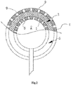
- a fixed layer 4 is located on the surface of the porous, oleophilic and hydrophobic layer 3 for limiting the flowing of the porous, oleophilic and hydrophobic layer 3, and a plurality of through holes are arranged uniformly on the fixed layer 4.
- the wall 1 of the oil gathering chamber 2 and the fixed layer 4 together form a separating chamber 5.
- said oil-water separating device further comprises a pipe communicated with the oil gathering chamber 2.
- the floating oil stored in the oil gathering chamber 2 can be extracted and collected conveniently without salvaging this oil-water separating device in advance.
- said porous, oleophilic and hydrophobic layer 3 can be of various porous material layers with oleophilic and hydrophobic property.
- said oleophilic and hydrophobic layer 3 is an accumulation of precoated silicon sand.
- said precoated silicon sand may be various precoated silicon sands with the oleophilic and hydrophobic property, which allow oil to flow into the voids among the precoated silicon sand and pass therethrough, while obstruct water outside of the precoated silicon sand.
- said precoated silicon sand in the present application is the silicon sand with the surface coated with a coating layer.
- Said precoated silicon sand with the surface coated with a coating layer is formed by mixing and curing the silicon sand with the oleophilic and hydrophobic resin.
- said through holes in said wall 1 of the oil gathering chamber 2 covered with the porous, oleophilic and hydrophobic layer 3 and in the fixed layer 4 are arranged for the purpose of facilitating the floating oil entering into said oil-water separating device and finally into the oil gathering chamber 2.
- the pore diameter of the through-holes mentioned above is preferably no larger than, and more preferably, smaller than the average particle diameter of said precoated silicon sand.
- the hole diameter of said through holes may be 100-400 ⁇ m.
- the sphericity of said precoated silicon sand may be more than 0.7, more preferably 0.7-0.95.
- Term "sphericity" means a measurement of relative sharpness or curvature of edges and corners of a particle, and it also means the degree of approaching a sphere of the particle. The method of measuring the sphericity is well known to the skilled person in this field. For example, a chart correction method can be used to measure it.
- the particle diameter of said precoated silicon sand may be 300-850 ⁇ m.
- the accumulation density may be 1.4-1.65%, preferably 1.4-1.5%.
- the thickness of said porous, oleophilic and hydrophobic layer 3 may be selected appropriately according to the amount of the floating oil on the water to be collected. If the floating oil layer is thinner, the thickness of the accumulation of the precoated silicon sand forming the porous, oleophilic and hydrophobic layer 3 is thinner, correspondingly. If the floating oil layer is thicker, the thickness of the accumulation of the precoated silicon sand forming the porous, oleophilic and hydrophobic layer 3 is thicker, correspondingly. Generally, the thickness of said porous, oleophilic and hydrophobic layer 3 may be 5-50mm, preferably 10-30mm.
- the selectable range of weight ratio of said oleophilic and hydrophobic resin to said silicon sand is relatively wide.
- the amount of the oleophilic and hydrophobic resin makes a coating layer with a thickness of 0.1-10 ⁇ m, more preferably 1-5 ⁇ m. Therefore, the mass ratio of the oleophilic and hydrophobic resin to the silicon sand may be 0.2-15:100.
- said oleophilic and hydrophobic resin may be various oleophilic and hydrophobic resins.
- Said oleophilic and hydrophobic resin preferably may be one or more resins selected from oleophilic and hydrophobic epoxy resin, oleophilic and hydrophobic phenolic resin, oleophilic and hydrophobic polyurethane resin, and oleophilic and hydrophobic silicon resin.
- oleophilic and hydrophobic resin is at least two resins selected from oleophilic and hydrophobic epoxy resin, oleophilic and hydrophobic phenolic resin, oleophilic and hydrophobic polyurethane resin, and oleophilic and hydrophobic silicon resin, a better oleophilic and hydrophobic property is obtained.
- the mass ratio between any two oleophilic and hydrophobic resins maybe 1:0.1-10.
- said oleophilic and hydrophobic epoxy resin may be one or more resins selected from glycidyl ether type epoxy resin, glycidyl ester type epoxy resin, glycidyl amine type epoxy resin, linear-aliphatic type epoxy resin, alicyclic type epoxy resin, polysulfide rubber modified epoxy resin, polyamide resin modified epoxy resin, polyvinyl tert-butyraldehyde modified epoxy resin, Nitrile rubber modified epoxy resin, phenolic resin modified epoxy resin, polyester resin modified epoxy resin, melamine urea formaldehyde resin modified epoxy resin, furfural resin modified epoxy resin, vinyl resin modified epoxy resin, isocyanate modified epoxy resin, and silicon resin modified epoxy resin.
- glycidyl ether type epoxy resin glycidyl ester type epoxy resin
- glycidyl amine type epoxy resin linear-aliphatic type epoxy resin
- alicyclic type epoxy resin polysulfide rubber modified epoxy resin
- polyamide resin modified epoxy resin polyvinyl ter
- Said oleophilic and hydrohobic phenolic resin may be one or two resins selected from dimethylbenzene modified phenolic resin, epoxy resin modified phenolic resin, and organosilicone modified phenolic resin.
- Said oleophilic and hydrophobic polyurethane resin may be a polyurethane resin prepared by one or more selected from oligomeric polyols such as organic polyisocyanate, polyether, polyester and the like.
- Said oleophilic and hydrophobic silicon resin may one or more selected from methyltrichlorosilane, dimethyldichlorosilance, phenyltrichlorosilane, diphenyldichlorosilane, and methylphenyl dichlorosilane .
- the method for curing the oleophilic and hydrophobic resin may be various common methods, such as curing by using a curing agent for curing or by photo-curing directly.
- the kinds of curing agent for curing may be various curing agents for curing the oleophilic and hydrophobic resin, which are well known to the skilled person in the art, and the range of the adjustable usage amount of the curing agent may be relatively wide.
- the weight ratio of said curing agent to said oleophilic and hydrophobic resin may be 1-25:100.
- the curing agent for said oleophilic and hydrophobic epoxy resin may be one or more selected from aliphatic amine, alicyclic amine, aromatic amine and its modification, polyamide, anhydride, tertiary amine and its salt, paraformaldehyde, imidazole, prepolymer, peroxide acyls, paraformaldehyde, and melamine resin.
- the curing agent for said oleophilic and hydrophobic phenolic resin may be hexamethylenetetramine.
- the curing agent for said oleophilic and hydrophobic polyurethane resin may be one or more selected from the addition product of toluene diisocyanate (TDI) and of trimethylolpropane (TMP), the prepolymer of toluene diisocyanate (TDI) and of Hydroxyl-containing components, and the tripolymer of single component moisture curing agent and of toluene diisocyanate (TDI).
- the curing agent for said oleophilic and hydrophobic organic silicon resin may be dibutyltin dilaurate and/or N,N,N',N'- Tetramethyl guanidine.
- the precoated silicon sand with the surface covered with a coating layer may be formed by mixing the silicon sand with the oleophilic and hydrophobic resin, the plasticizer and/or the lubricant, and then by curing the mixture thereof.
- the kinds and the usage amount of the plasticizer is well known for the skilled person in the art.
- the plasticizer is mainly used to reduce elasticity modulus and tensile breaking strength, to improve flexibility, reversible bending strength, toughness and impact strength, to reduce glass-transition temperature, to expand the applicability of the polymer at lower temperatures, to improve the bonding with various basic materials, and the like.
- the weight ratio of said plasticizer to said oleophilic and hydrophobic resin may be 5-25:100.
- Said plasticizer may be preferably one or more selected from phthalic acid ester, aliphatic acid ester, and phosphate ester.
- Said phthalic acidester may be dimethyl phthalate.
- Said aliphatic acid ester may be one or more selected from diglycol diformate, ethylene diformate and diethylene glycol diformate.
- Said phosphate ester may be one or more selected from triaryl phosphate, tri-isopropylatedphenyl phosphateeste (IPPP) and phenyl ether phosphate.
- the kinds and the usage amount of said lubricant are well known for the skilled person in the art.
- the lubricant is mainly used to improve lubricating property, to reduce friction and static electricity, and to improve surface gloss and appearance.
- the weight ratio of said lubricant to said oleophilic and hydrophobic resin may be 1-10:100.
- Said lubricant may be one or more selected from polyethylene wax, oxidized polyethlene wax, octadecanamide, calcium stearate, zinc stearate and ethylene bis stearamide.
- the conditions under which the silicon sand, the oleophilic and hydrophobic resin and the optional plasticizer and/or lubricant are mixed together and cured may be the common conditions in the art. For example, it can firstly heat the silicon sand particles to the temperature of 50-400°C, preferably 100-240°C; then mix the heated silicon sands with the oleophilic and hydrophobic resin, the optional plasticizer and/or lubricant, and stir the mixture uniformly. There are no special demands for the stirring temperature, as long as it allows said oleophilic and hydrophobic resin adhering to the surface of the silicon sand particles uniformly.
- the stirring time preferably is 1-10 minutes.
- the curing condition may be as follows: the curing temperature may be 20-150 °C, the curing time may be 0.1-24 hours, and the curing humidity may be 5-35%.
- the adding sequence of said oleophilic and hydrophobic resin, the plasticizer and the lubricant substantially has no influence on the property of precoated silicon sand obtained in the present disclosure.
- the oleophilic and hydrophobic resin, the plasticizer, and the lubricant may be added at the same time, to be mixed with the silicon sand.
- the oleophilic and hydrophobic resin, the plasticizer, and the lubricant may be added in different steps.
- the oleophilic and hydrophobic resin may firstly be mixed with the silicon sand, and then be mixed with the plasticizer and/or the lubricant.
- the precoated silicon sand may also be obtained by cooling, crushing and screening so as to control the particle diameter thereof.
- cooling, crushing and screening There are no special demands on the cooling conditions, but it's preferably cooled down to the room temperature.
- common methods for crushing and screening may be used to obtain the precoated silicon sand with the particle diameter according to the present disclosure.
- the present disclosure further provides a floating oil collecting system.
- This system comprises at least one oil-water separating device which is just the oil-water separating device provided in the present disclosure whereby there may be a plurality of said oil-water separating devices, which preferably are positioned uniformly on the water surface containing floating oil so that the floating oil collection may be performed on the water surface with larger area, even on the sea surface, so as to enhance the collecting efficiency.
- a plurality of oil-water separating devices may be fixed by means of flexible connections. For example, the steel wire, the thin coiler and the thin rope may be used to connect the plurality of oil-water separating devices and to position them on the water surface, uniformly.
- said floating oil collecting system may further comprise a pump, and a pipe for connecting the pump and the oil gathering chamber of each oil-water separating device, so as to pump the collected floating oil at the same time.
- said floating oil collecting system may further comprise an oil gathering device so as to store the floating oil coming from the pump.
- said floating oil collecting system may further comprise a hull so as to accommodate the oil gathering device.
- the method for collecting the floating oil on the water surface by using said floating oil collecting system of the present disclosure may comprise the steps as follows: position said oil-water separating device according to the present disclosure on the water surface containing floating oil, so as to make at least part of the surface of the fixed layer 4, which covers on the surface of the porous, oleophilic and hydrophobic layer 3 for limiting the flowing of the porous, oleophilic and hydrophobic layer, contact with the water surface containing floating oil; and collect the floating oil within the oil gathering chamber.
- said oil-water separating device is positioned on the water surface containing floating oil, and it needs to make at least part of, preferably 30%-80% of, surface of the fixed layer 4, which covers on the surface of the porous, oleophilic and hydrophobic layer 3 for limiting the flowing of the porous, oleophilic and hydrophobic layer, contact with the water surface containing floating oil, so that the oil-water enters into the oil-water separating chamber via the through holes on the fixed layer 4 and contacts with the porous, oleophilic and hydrophobic layer 3 therein, in order to achieve collecting the floating oil effectively.
- the entire surface of said wall 1 is covered with the porous, oleophilic and hydrophobic layer 3.
- the present disclosure has no special demands on the method for positioning the oil-water separating device on the water surface containing floating oil, and various common methods may be used.
- said oil-water separating device may be floating on the water surface containing floating oil by using a buoyancy device, or said oil-water separating device may be hanging above the water surface containing floating oil.
- said method for collecting the floating oil on the water surface may further comprise importing the floating oil within each oil gathering chamber into a storage unit so as to store the floating oil.
- the method for importing the floating oil within each oil gathering chamber into the storage unit comprises arranging a pipe communicated with each oil gathering chamber, and importing the floating oil within each oil gathering chamber into the storage unit through said pipe.
- the pipe communicated with each oil gathering chamber is connected with a pump.
- the floating oil is pumped from each oil gathering chamber and imported into the storage unit by said pump.
- this method may further comprise carrying away the storage unit loaded with the floating oil.
- a hull may be used as the storage unit to facilitate the transportation.
- Said floating oil collecting system comprises a hull 1, an oil gathering device 2 placed on the hull, a pump 3, a pipe 5 for connecting the pump 3 with an oil gathering chamber of the oil-water separating device 4.
- Said method for collecting the floating oil on the water surface comprises the step of positioning the oil-water separating device 4 on the water surface containing a floating oil layer 6, to make said oil-water separating device 4 floating on the water surface.
- Said oil-water separating device comprises an oil gathering chamber surrounded by a wall.
- the entire surface of the wall forming the oil gathering chamber is covered with the porous, oleophilic and hydrophobic layer (preferably 30-80% of the volume of said oil-water separating device is located under the water surface containing floating oil).
- a plurality of through holes are distributed uniformly on the wall of the oil gathering chamber covered with the porous, oleophilic and hydrophobic layer.
- a fixed layer is covered on the surface of the porous, oleophilic and hydrophobic layer for limiting the flowing of the porous, oleophilic and hydrophobic layer, and a plurality of through-holes are distributed uniformly on the fixed layer.
- the fixed layer and the wall of said oil gathering chamber forms a separating chamber.
- Said porous, oleophilic and hydrophobic layer is an accumulation of the precoated silicon sands, and is filled within the separating chamber. After a period of collecting, the pump 3 is actuated to collect the floating oil in the oil gathering chamber of the oil-water separating device 4 through the pipe 5, and the collected floating oil is stored in the oil gathering device 2.
- the quartz sand may be commercially obtained from Yong Deng Blue Sky Quartz Sand Co., Ltd.
- the manufactures and the brands for the oleophilic and hydrophobic resin, the curing agent and the plasticizer may be as follows:
- the particular testing method is Soxhlet extraction- UV spectrophotometry.
- Aromatic compounds with benzene ring mainly absorb a wavelength of 250-260nm.
- Compounds with conjugated double bond mainly absorb a wavelength of 215-230nm.
- the ultraviolet absorption method often adopts a double-wavelength measurement.
- two main absorption wavelengths of crude oil are 225nm and 254nm.
- the absorption peak of fuel oil, lubricating oil and the like is close to that of crude oil. Therefore, the wavelength selection should be depending on the actual case.
- a wavelength of 254nm may be selected for crude oil and heavy oil, while a wavelength of 225nm may be selected for light oil and oils from oil refinery.
- Soxhlet extraction- UV spectrophotometry uses Soxhlet extractor to extract the crude oil from the oily sludge by circulating reflux for six hours. Benzinum or mixed heptane is usually used as the extracting agent. The oil content is measured through double-wavelength by using an ultraviolet spectrophotometer.
- microballoon silica gel with a particle diameter of 60-100 mesh and neutral chromatography aluminum oxide with a particle diameter of 70-120 mesh (activation at 150-160°C for 4 hours) are put into a glass column with an inner diameter of 25mm and a height of 750 mm, by using Column Chromatography, before completely cooling.
- the lower layer of the silica gel has a height of 600mm, and aluminum oxide with a thickness of 50mm is covered thereon; then a de -aromatization is performed for the benzinum (fraction at 60-90 °C) sold in the market through this column.
- Benzinum is collected in a narrow-necked bottle. Water is used to be a reference for measuring the transmittance of the treated Benzinum, which is no less than 80%, at a position corresponding to the marking line of 225nm on an ultraviolet spectrophotometer.
- Standard oil usage solutions with a volume of 0, 2.00, 4.00, 8.00, 12.00, 20.00 and 25.00 ml are respectively added into seven measuring flasks with a volume of 70ml, and diluted to reach the marking line by using benzinum (60-90°C).
- benzinum 60-90°C
- a 1 cm quartz cuvette is used as reference for measuring an absorbance, and upon which plotting a standard curve.
- This example is used to describe the preparation of the precoated silicon sand with its surface covered with an oleophilic and hydrophobic film provided in the present disclosuredisclosure.
- This example is used to describe the preparation of the precoated silicon sand with its surface covered with an oleophilic and hydrophobic film provided in the present disclosure.
- the precoated particles are prepared by the same method as that of Preparation Example 1, expect for that dimethyl phthalate (DMP) is added as a plasticizer before adding the curing agent.
- the weight ratio of the plasticizer to the resin is 10:100.
- the thickness of the coating layer of the obtained precoated silicon sand is 2-3 micrometer.
- the sphericity of the precoated silicon sand is 0.75 and the particle diameter distribution is 350-430 micrometer.
- This example is used to describe the preparation of the precoated silicon sand with its surface covered with an oleophilic and hydrophobic film provided in the present disclosure.
- the precoated particles are prepared by the same method as that of Preparation Example 1, expect for that polyethylene wax is added as a lubricant before the resin begins to cure and cluster.
- the weight ratio of the lubricant to the resin is 2:100.
- the thickness of the coating layer of the obtained precoated silicon sand is 0.5-1 micrometer.
- the sphericity of the precoated silicon sand is 0.78 and the particle diameter distribution is 380-420 micrometer.
- This example is used to describe the preparation of the precoated silicon sand with its surface covered with an oleophilic and hydrophobic film provided in the present disclosure.
- the precoated particles are prepared by the same method as that of Preparation example 1, expect for that the weight ratio of the polyamide resin modified epoxy resin to the quarts sand particle is 0.5:100.
- the thickness of the coating layer of the obtained precoated silicon sand is 0.1-0.5 micrometer.
- the sphericity of the precoated silicon sand is 0.73 and the particle diameter is 350-430 micrometer.
- This example is used to describe the preparation of the precoated silicon sand with its surface covered with an oleophilic and hydrophobic film provided in the present disclosure.
- the precoated particles are prepared by the same method as that of Preparation example 1, expect for that the weight ratio of the polyamide resin modified epoxy resin to the quarts sand particle is 12:100.
- the thickness of the coating layer of the obtained precoated silicon sand is 4-5 micrometer.
- the sphericity of the precoated silicon sand is 0.75 and the particle diameter is 360-450 micrometer.
- This example is used to describe the preparation of the precoated silicon sand with its surface covered with an oleophilic and hydrophobic film provided in the present disclosure.
- This example is used to describe the preparation of the precoated silicon sand with its surface covered with an oleophilic and hydrophobic film provided in the present disclosure.
- This example is used to describe the preparation of the precoated silicon sand with its surface covered with an oleophilic and hydrophobic film provided in the present disclosure.
- the precoated particles are prepared by the same method as that of Preparation Example 1, expect for that organic silicon resin is used instead of polyamide resin modified epoxy resin, and for that dibutyltin dilaurate is used as a curing agent.
- the thickness of the coating layer of the obtained precoated silicon sand is 1-2 micrometer.
- the sphericity of the precoated silicon sand is 0.75 and the particle diameter is 320-450 micrometer.
- This Example is used to describe the preparation of the precoated silicon sand with its surface covered with an oleophilic and hydrophobic film provided in the present disclosure.
- the precoated particles are prepared by the same method as that of Preparation Example 1, expect for that polyurethane resin is used instead of polyamide resin modified epoxy resin, and for that TDI Tripolymer is used as a curing agent.
- the thickness of the coating layer of the obtained precoated silicon sand is 1-2 micrometer.
- the sphericity of the precoated silicon sand is 0.73 and the particle diameter is 320-450 micrometer.
- This example is used to describe the preparation of the precoated silicon sand with its surface covered with an oleophilic and hydrophobic film provided in the present disclosure.
- the precoated particles are prepared by the same method as that of Preparation Example 1, expect for that polytetrafluoroethylene is used instead of polyamide resin modified epoxy resin, and for that no curing agent is used.
- the thickness of the coating layer of the obtained precoated silicon sand is 1-2 micrometer.
- the sphericity of the precoated silicon sand is 0.71 and the particle diameter is 320-450 micrometer.
- This Example is used to describe the preparation of the precoated silicon sand with its surface covered with an oleophilic and hydrophobic film provided in the present disclosure.
- the precoated particles are prepared by the same method as that of Preparation Example 1, expect for that polydimethylsiloxane is used instead of polyamide resin modified epoxy resin, and for that no curing agent is used.
- the thickness of the coating layer of the obtained precoated silicon sand is 1-2 micrometer.
- the sphericity of the precoated silicon sand is 0.73 and the particle diameter is 320-450 micrometer.
- This example is used to describe the preparation of the precoated silicon sand with its surface covered with an oleophilic and hydrophobic film provided in the present disclosure.
- the precoated particles are prepared by the same method as that of Preparation Example 1, expect for that 2kg of polyamide resin modified epoxy resin and 1kg of polyvinyl tert-butyraldehyde modified epoxy resin are used instead of 3kg of polyamide resin modified epoxy resin.
- the thickness of the coating layer of the obtained precoated silicon sand is 1-2 micrometer.
- the sphericity of the precoated silicon sand is 0.75 and the particle diameter is 320-450 micrometer.
- This example is used to describe the preparation of the precoated silicon sand with its surface covered with an oleophilic and hydrophobic film provided in the present disclosure.
- the precoated particles are prepared by the same method as that of Preparation example 1, expect for that 0.5kg of polyvinyl tert-butyraldehyde modified epoxy resin and 2.5 kg of dimethylbenzene are modified phenolic resin are used instead of polyamide resin modified epoxy resin , and for that polyamide (with a weight ratio 5:100 of the polyamide to the polyvinyl tert-butyraldehyde modified epoxy resin) and hexamethylenetetramine (with a weight ratio 5:100 of the hexamethylenetetramine to the dimethylbenzene modified phenolic resin) are used as curing agents.
- the thickness of the coating layer of the obtained precoated silicon sand is 1-2 micrometer.
- the sphericity of the precoated silicon sand is 0.78 and the particle diameter is 320-450 micrometer.
- This Example is used to describe the preparation of the precoated silicon sand with its surface covered with an oleophilic and hydrophobic film provided in the present disclosure.
- the precoated particles are prepared by the same method as that of Preparation example 1, expect for that 0.5kg of polyvinyl tert-butyraldehyde modified epoxy resin, 1.5 kg of dimethylbenzene modified phenolic resin and 1 kg of organic silicon resin are used instead of polyamide resin modified epoxy resin, and for that polyamide (with a weight ratio 5:100 of the polyamide to the polyvinyl tert-butyraldehyde modified epoxy resin), hexamethylenetetramine (with a weight ratio 5:100 of the hexamethylenetetramine to the dimethylbenzene modified phenolic resin) and Dibutyltin dilaurate (with a weight ratio 5:100 of the Dibutyltin dilaurate to the organic silicon resin) are used as curing agents.
- the thickness of the coating layer of the obtained precoated silicon sand is 1-2 micrometer.
- the sphericity of the precoated silicon sand is 0.82 and the particle diameter is
- This example is used to describe the preparation of the precoated silicon sand with its surface covered with an oleophilic and hydrophobic film provided in the present disclosure.
- the precoated particles are prepared by the same method as that of Preparation example 1, expect for that 1.5kg of polyvinyl tert-butyraldehyde modified epoxy resin and 1.5 kg of polyurethane resin are used instead of polyamide resin modified epoxy resin, and for that polyamide (with a weight ratio 5:100 of the polyamide to the polyvinyl tert-butyraldehyde modified epoxy resin) and TDI Tripolymer (with a weight ratio 5:100 of the TDI Tripolymer to the polyurethane resin) are used as curing agents.
- the thickness of the coating layer of the obtained precoated silicon sand is 1-2 micrometer.
- the sphericity of the precoated silicon sand is 0.78 and the particle diameter is 320-450 micrometer.
- This example is used to illustrate the preparation of the oil-water separating device provided in the present disclosure.
- a spherical oil gathering chamber with a volume of 50 ml (it is formed of PC polycarbonate material, and an oil port communicated with pipes is opened at the top of the oil gathering chamber) within another spherical chamber (it is formed of polycarbonate material); and filling precoated silicon sands (about 30 ml) prepared according to Preparation Examples 1-15 between the wall of the oil gathering chamber and the wall of another spherical chamber, to form a porous, oleophilic and hydrophobic layer; the wall of said another spherical chamber is used to fix the precoated silicon sands filled therebetween, to make said porous, oleophilic and hydrophobic layer covering the wall of said oil gathering chamber; the wall of said oil gathering chamber and the wall of another spherical chamber both have a plurality of through-holes distributed uniformly.
- the floating oil collecting system is used to collect the floating oil on the water surface.
- Said floating oil collecting system comprises a hull, an oil gathering device placed on the hull, a pump, and a pipe for connecting the pump with an oil gathering chamber of the oil-water separating device.
- Said method for collecting the floating oil on the water surface comprises the following steps: connecting 20 oil-water separating devices provided in the Examples mentioned-above by using steel wires; positioning said oil-water separating devices on the water surface containing floating oil layer (each oil-water separating device is spaced apart by 15-20 cm with each other, 40-50% of the volume of each oil-water separating device is under the water surface containing floating oil) (the floating oil is floating on the water surface at 1 liter per square meter, and the density of the floating oil is 0.7-0.8g/cm 3 ); actuating the pump after collecting for 2.5 hours, and delivering the floating oil collected in the oil gathering chamber of the oil-water separating device to the oil gathering device and storing therein; the oil absorption rate is shown in Table One.
- the present example is used to illustrate the preparation of the oil-water separating device provided in the present disclosure.
- a cubic body with a volume of 100 ml is used as the oil gathering chamber (it is formed of PC polycarbonate material, and an oil port communicated with a pipe is opened at the side of the oil gathering chamber), the precoated silicon sands prepared according to Example One are covered on a part of the surface of the oil gathering chamber to form the porous, oleophilic and hydrophobic layer.
- the porosity of the porous, oleophilic and hydrophobic layer is 35%, the hole diameter is 480 micrometer, the accumulation density is 1.48g/cm 3 , and the thickness is 30mm; a fixed layer is formed on the surface of said porous, oleophilic and hydrophobic layer for limiting the flowing of said porous, oleophilic and hydrophobic layer, and a plurality of through holes (the hole diameter is 300 micrometer) are distributed on the fixed layer uniformly; the upper surface of said oil gathering chamber and the fixed layer together form an oil-water separating chamber, the porous, oleophilic and hydrophobic layer is filled within said oil-water separating chamber (the filling volume of the precoated silicon sand is about 30 ml).
- the wall of the upper surface of said oil gathering chamber has a plurality of through holes (the diameter of the through hole is 300 micrometer).
- the floating oil is collected according to the method of Examples 1-15, except for that 80 % of the surface of the fixed layer covering the surface of the porous, oleophilic and hydrophobic layer for limiting the flowing of the porous, oleophilic and hydrophobic layer is contacting with the water surface containing floating oil; the oil absorption rate is shown in Table One. Table One Embodiment No.
- Embodiment 1 20 0.3 20 0.45 1.56 60 Embodiment 2 20 0.3 25 0.48 1.58 65 Embodiment 3 20 0.3 30 0.52 1.57 67 Embodiment 4 20 0.3 22 0.46 1.60 62 Embodiment 5 20 0.3 21 0.45 1.48 61 Embodiment 6 20 0.3 25 0.48 1.59 62 Embodiment 7 20 0.3 20 0.47 1.53 75 Embodiment 8 20 0.3 28 0.55 1.56 65 Embodiment 9 20 0.3 26 0.50 1.55 70 Embodiment 10 20 0.3 20 0.47 1.53 72 Embodiment
- the oil absorption rate is the percentage of oil in the oil-water mixture collected in the oil gathering chamber.
- the oil absorption is mainly presented by the ability of oil permeability and water resist of the oleophilic and hydrophobic layer in said oil collecting device according to the present disclosure; the better the effect of oil permeability and water resist of the oleophilic and hydrophobic layer is, the higher the absorption rate is.
- the remaining contents of the floating oil per square meter is only 1-2% of the volume of the floating oil on the water surface before collecting.
- the remaining contents of the floating oil per square meter is only 2% of the volume of the floating oil on the water surface before collecting.
Landscapes
- Engineering & Computer Science (AREA)
- General Engineering & Computer Science (AREA)
- Chemical & Material Sciences (AREA)
- Civil Engineering (AREA)
- Environmental & Geological Engineering (AREA)
- Mechanical Engineering (AREA)
- Structural Engineering (AREA)
- Chemical Kinetics & Catalysis (AREA)
- Thermal Sciences (AREA)
- Physics & Mathematics (AREA)
- Oil, Petroleum & Natural Gas (AREA)
- Removal Of Floating Material (AREA)
- Cleaning Or Clearing Of The Surface Of Open Water (AREA)
Description
- The present invention relates to an oil-water separating device and a floating oil collecting system comprising same.
- The oil around the world is transported mainly by means of marine transportation while serious oil spill accidents will occur due to stranding, impacting, striking a rock and structure damage of the hull itself during the sailing of a tanker. At the meantime, more and more sea drilling platforms and floating pipe lines have been successively established, by which safety problems of environment or of their own structure may exist; this leads to oil spill accidents, results in a large area of floating oil on the sea. Therefore, the negative influences caused by the floating oil will be minimized by effective floating oil recovering methods and advanced floating oil recovering devices.
- The current floating oil collecting device that has a function of collecting and processing only works for oil floating on water with smaller area and less amount of liquids, but it is powerless for handling the case in which large quantities of floating oil caused by capsizing or leaking of a large and giant tanker is spreading on a large sea area. For example, current floating oil collectors first suck in floating oil on the water surface and part of water, by a floating oil suction inlet, based on the fact that water and oil have different densities; the oil-water mixture is sent to a vortex type floating oil separator by a reciprocation pump; the oil-water mixture is separated in the separator; the floating oil is accumulated in the separator and discharged automatically; the water that has been separated from floating oil is returned to the sea by a return pipe. For example,
CN2122860U has disclosed a floating oil collector mainly consisting of a water pump, an oil pump, a floating body and an open container. This floating oil collector utilizes the difference in local water level, the laminar flow rate and the principle of fluid viscosity, to collect the floating oil directly in the water contained floating oil. For another example,CN101565942A has disclosed a marine, shovel type, floating oil collector, the main structure thereof consists of an air cushion, a balancing wing and a floating oil inlet control device. Floating oil enters through the oil inlet control device and passes a fine mesh, so as to filter impurity substances floating on the sea; the mixture entering the oil -water separating pool is subjected to an oil-water separating process by using the principle that floating oil and sea water have different densities. The floating oil being separated is floating on sea water, and the underlying seawater is discharged through an outlet; at this moment the oil pump is opened to collect floating oil and store it in a flexible oil bag. However, the method of current technology is poor in floating oil collection efficiency, thus is not suitable for large area of floating oil collection on sea. -
US3830371 discloses an apparatus for separating a mixture of heavier and lighter liquids capable, of separating into-two separate phases is disclosed. The mixture is passed through confined particle material which, preferably, has an affinity for one of the liquids. The particles are confined in a cylindrically shaped space and the liquids move through the particles in a radial and horizontal direction. The particle material filters the liquids and aids in "coalescing the liquid for which the "particles have affinity. The liquids separate by gravity and are discharged separately. The particles are backwashed periodically to remove collected solids. During the backwash operation the particles are unconfined and are flushed by upward flow of backwash liquid into a space which is larger in cross-section than the cross-section in which the particles are confined during filtering-coalescing operations. Following backwashing the particles, which have a greater density than the backwash liquid, settle' by gravity to their filtering-coalescing position and are again confined. - The object of the present invention is to overcome the defects that the floating oil collecting device in the prior art is poor in floating oil collection efficiency and is not suitable for large area of floating oil collection on sea, and to provide an oil-water separating device and a floating oil collecting system comprising same which has high efficiency in floating oil collection and is suitable for large area of floating oil collection on sea.
- The present invention provides an oil-water separating device. The device comprises an oil gathering chamber enclosed by a wall. At least a part of surface of the wall is covered with a porous, oleophilic and hydrophobic layer, which allows penetration of water and oil. The device also comprises a fixed layer covering on the surface of the porous, oleophilic and hydrophobic layer for limiting the flowing of the porous, oleophilic and hydrophobic layer, and the fixed layer allows the penetration of water and oil. The pore diameter of said porous, oleophilic and hydrophobic layer is 300-850 µm, the porosity is 10-40% and other features are further specified in
claim 1. - The present invention also provides a floating oil collecting system, which comprises at least one oil-water separating device, wherein said oil-water separating device is just the oil-water separating device provided by the present invention.
- In the oil-water separating device provided in the present disclosure at least a part of the surface of the wall enclosing the oil gathering chamber is covered with a porous, oleophilic and hydrophobic layer. Therefore, after contacting with the oleophilic and hydrophobic layer, the floating oil can flow into the void among silican sands covered with oleophilic and hydrophobic membrane due to the small interface tension, and flow into the oil gathering chamber though the through-hole in the wall of the oil gathering chamber covered with the porous, oleophilic and hydrophobic layer, while after contacting with the oleophilic and hydrophobic layer, the water is substantially obstructed outside of the oleophilic and hydrophobic layer due to large interface tension thereof, or only small quantity of water can penetrate, or even no water penetrates at all. Therefore, the purpose of oil-water separating is obtained. More surprisingly, by using the floating oil collecting system comprising the oil-water separating device of the present invention, a large area of floating oil on sea can be collected effectively, and the floating oil collection efficiency can be improved significantly.
-
-
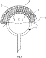
Fig.1 is a schematic diagram showing the partial section view of the oil-water separating device according to the present invention; -
Fig.2 is a schematic diagram showing the partial section view of the oil-water separating device according to the present invention; -
Fig.3 is a schematic diagram of the floating oil collecting system according to the present invention. - According to the present disclosure, said oil-water separating device comprises an
oil gathering chamber 2 enclosed with awall 1. At least a part of the surface of thewall 1 is covered with a porous, oleophilic andhydrophobic layer 3, the portion ofsaid wall 1 covered with the porous, oleophilic andhydrophobic layer 3 allows penetration of water and oil. The device also comprises afixed layer 4 covering on or over the surface of the porous, oleophilic andhydrophobic layer 3 for limiting the flowing of the porous, oleophilic and hydrophobic layer, and thefixed layer 4 allows penetration of water and oil. The pore diameter of said porous, oleophilic andhydrophobic layer 3 is 300-850 µm, preferably 300-600µm; the porosity is 10-40%, preferably 20-35%. Said pore diameter can be measured by an Electron Microscope. Said porosity can be measured by a mercury intrusion method. The detailed steps are as follows: press the mercury into the porous media to replace the air in the void; measure the mass difference of the sample before and after pressing the mercury, to obtain the void volume; divide the void volume by the appearance volume to obtain the porosity. - Using said oil-water separating device of the present disclosure, when the pressure difference of the oleophilic and hydrophobic layer is 0-20kPa, the volume flow ratio of oil to water that are penetrating through the oleophilic and hydrophobic layer can reach 1.5-3:1.
- As shown in
Fig.1 , said oil-water separating device comprises anoil gathering chamber 2 enclosed with awall 1. A part of the surface of thewall 1 is covered with a porous, oleophilic andhydrophobic layer 3, the portion ofsaid wall 1 covered with the porous, oleophilic andhydrophobic layer 3 allows penetration of water and oil. The device also comprises afixed layer 4 covering on the surface of the porous, oleophilic andhydrophobic layer 3 for limiting the flowing of the porous, oleophilic and hydrophobic layer, and thefixed layer 4 allows penetration of water and oil. - Preferably, for the purpose of enhancing the oil gathering efficiency, the entire surface of
said wall 1 is covered with the porous, oleophilic andhydrophobic layer 3. - According to the present disclosure, said
wall 1 enclosing theoil gathering chamber 2 and said fixedlayer 4 may be of various shapes and materials (such as plastics) which allow penetration of water and oil to collect the floating oil and limit the flowing of said porous, oleophilic and hydrophobic layer. Preferably, thewall 1 and thefixed layer 4 are both plates. There are a plurality of means to allow penetration of water and oil. Preferably, thefixed layer 4 and the portion ofsaid wall 1 covered with the porous, oleophilic andhydrophobic layer 3 have a plurality of through holes such that thefixed layer 4 and the portion ofsaid wall 1 that is covered with the porous, oleophilic andhydrophobic layer 3 can allow penetration of water and oil via the through holes. Although the portion ofsaid wall 1 covered with the porous, oleophilic andhydrophobic layer 3 allows penetration of water and oil, only the oil can pass through said porous, oleophilic and hydrophobic layer and saidwall 1 easily and enter into the oil gathering chamber, but water penetration will be prevented or only small quantity of water can penetrate said porous, oleophilic and hydrophobic layer to reach the surface of thewall 1 and pass through thewall 1 into the oil gathering chamber, because the porous, oleophilic and hydrophobic layer has the oleophilic and hydrophobic property. In order to facilitate the water and oil penetrating the fixed layer smoothly and rapidly to contact with the porous, oleophilic and hydrophobic layer such that the oil can enter into the oil gathering chamber through thewall 1 rapidly, said through-holes are arranged uniformly on thefixed layer 4 and the portion ofsaid wall 1 covered with the porous, oleophilic andhydrophobic layer 3. According to the disclosure mentioned-above, an oil-water separatingchamber 5 is preferably formed between thewall 1 and thefixed layer 4. The porous, oleophilic andhydrophobic layer 3 is filled within the oil-water separatingchamber 5 so as to further facilitate oil-water separating and oil gathering. Furthermore, the shape of the fixed layer may be formed according to the shape of the oil gathering chamber engaging therewith so that the oil-water separatingchamber 5 has the shape engaging with theoil gathering chamber 2. - According to the present disclosure, the shape of the
oil gathering chamber 2 may be of various shapes adapted to collect the floating oil on water surface, such as a sphere, a cylinder or a cone. The volume of the oil gathering chamber in the oil-water separating device may be selected according to the area of waters. Generally, the volume of theoil gathering chamber 2 may be 50-100ml. - As shown in
Fig.2 , said oil-water separating device comprises anoil gathering chamber 2 enclosed with awall 1. The entire surface of thewall 1 of theoil gathering chamber 2 is covered with a porous, oleophilic andhydrophobic layer 3, thewall 1 of theoil gathering chamber 2 covered with the porous, oleophilic andhydrophobic layer 3 has a plurality of through holes arranged uniformly. A fixedlayer 4 is located on the surface of the porous, oleophilic andhydrophobic layer 3 for limiting the flowing of the porous, oleophilic andhydrophobic layer 3, and a plurality of through holes are arranged uniformly on the fixedlayer 4. Thewall 1 of theoil gathering chamber 2 and the fixedlayer 4 together form a separatingchamber 5. - According to the present disclosure, preferably, said oil-water separating device further comprises a pipe communicated with the
oil gathering chamber 2. The floating oil stored in theoil gathering chamber 2 can be extracted and collected conveniently without salvaging this oil-water separating device in advance. - According to the present disclosure, said porous, oleophilic and
hydrophobic layer 3 can be of various porous material layers with oleophilic and hydrophobic property. Preferably, in order to further improve the oil-water separation effect of filtering the floating oil, said oleophilic andhydrophobic layer 3 is an accumulation of precoated silicon sand. According to the present disclosure, said precoated silicon sand may be various precoated silicon sands with the oleophilic and hydrophobic property, which allow oil to flow into the voids among the precoated silicon sand and pass therethrough, while obstruct water outside of the precoated silicon sand. Preferably, said precoated silicon sand in the present application is the silicon sand with the surface coated with a coating layer. Said precoated silicon sand with the surface coated with a coating layer is formed by mixing and curing the silicon sand with the oleophilic and hydrophobic resin. - According to the present disclosure, said through holes in said
wall 1 of theoil gathering chamber 2 covered with the porous, oleophilic andhydrophobic layer 3 and in the fixedlayer 4 are arranged for the purpose of facilitating the floating oil entering into said oil-water separating device and finally into theoil gathering chamber 2. In order to prevent the precoated silicon sand from being taken along with the floating oil to penetrate said precoated silicon sand and flow into theoil gathering chamber 2 via the through holes of the oil gathering chamber, and prevent the precoated silicon sand from flowing out via the through holes on the fixedlayer 4 to influence the oil-water separating effect, the pore diameter of the through-holes mentioned above (including the through-holes in thewall 1 of theoil gathering chamber 2 that is covered with the porous, oleophilic and hydrophobic layer and the through-holes in the fixed layer 4) is preferably no larger than, and more preferably, smaller than the average particle diameter of said precoated silicon sand. For example, the hole diameter of said through holes may be 100-400 µm. - The better the sphericity of said precoated silicon sand is, the more possible it is to ensure that the void diameter of the precoated silicon sand is smaller and uniform so as to further improve the oil penetration effect. Therefore, the sphericity of said precoated silicon sand may be more than 0.7, more preferably 0.7-0.95. Term "sphericity" means a measurement of relative sharpness or curvature of edges and corners of a particle, and it also means the degree of approaching a sphere of the particle. The method of measuring the sphericity is well known to the skilled person in this field. For example, a chart correction method can be used to measure it. The particle diameter of said precoated silicon sand may be 300-850 µm. The accumulation density may be 1.4-1.65%, preferably 1.4-1.5%.
- According to the present disclosure, the thickness of said porous, oleophilic and
hydrophobic layer 3 may be selected appropriately according to the amount of the floating oil on the water to be collected. If the floating oil layer is thinner, the thickness of the accumulation of the precoated silicon sand forming the porous, oleophilic andhydrophobic layer 3 is thinner, correspondingly. If the floating oil layer is thicker, the thickness of the accumulation of the precoated silicon sand forming the porous, oleophilic andhydrophobic layer 3 is thicker, correspondingly. Generally, the thickness of said porous, oleophilic andhydrophobic layer 3 may be 5-50mm, preferably 10-30mm. - According to the present disclosure, the selectable range of weight ratio of said oleophilic and hydrophobic resin to said silicon sand is relatively wide. Preferably the amount of the oleophilic and hydrophobic resin makes a coating layer with a thickness of 0.1-10 µm, more preferably 1-5µm. Therefore, the mass ratio of the oleophilic and hydrophobic resin to the silicon sand may be 0.2-15:100.
- According to the present disclosure, said oleophilic and hydrophobic resin may be various oleophilic and hydrophobic resins. Said oleophilic and hydrophobic resin preferably may be one or more resins selected from oleophilic and hydrophobic epoxy resin, oleophilic and hydrophobic phenolic resin, oleophilic and hydrophobic polyurethane resin, and oleophilic and hydrophobic silicon resin.
- More preferably, when said oleophilic and hydrophobic resin is at least two resins selected from oleophilic and hydrophobic epoxy resin, oleophilic and hydrophobic phenolic resin, oleophilic and hydrophobic polyurethane resin, and oleophilic and hydrophobic silicon resin, a better oleophilic and hydrophobic property is obtained. Further preferably, the mass ratio between any two oleophilic and hydrophobic resins maybe 1:0.1-10.
- In particular, said oleophilic and hydrophobic epoxy resin may be one or more resins selected from glycidyl ether type epoxy resin, glycidyl ester type epoxy resin, glycidyl amine type epoxy resin, linear-aliphatic type epoxy resin, alicyclic type epoxy resin, polysulfide rubber modified epoxy resin, polyamide resin modified epoxy resin, polyvinyl tert-butyraldehyde modified epoxy resin, Nitrile rubber modified epoxy resin, phenolic resin modified epoxy resin, polyester resin modified epoxy resin, melamine urea formaldehyde resin modified epoxy resin, furfural resin modified epoxy resin, vinyl resin modified epoxy resin, isocyanate modified epoxy resin, and silicon resin modified epoxy resin.
- Said oleophilic and hydrohobic phenolic resin may be one or two resins selected from dimethylbenzene modified phenolic resin, epoxy resin modified phenolic resin, and organosilicone modified phenolic resin.
- Said oleophilic and hydrophobic polyurethane resin may be a polyurethane resin prepared by one or more selected from oligomeric polyols such as organic polyisocyanate, polyether, polyester and the like.
- Said oleophilic and hydrophobic silicon resin may one or more selected from methyltrichlorosilane, dimethyldichlorosilance, phenyltrichlorosilane, diphenyldichlorosilane, and methylphenyl dichlorosilane .
- According to the present disclosure, the method for curing the oleophilic and hydrophobic resin may be various common methods, such as curing by using a curing agent for curing or by photo-curing directly. The kinds of curing agent for curing may be various curing agents for curing the oleophilic and hydrophobic resin, which are well known to the skilled person in the art, and the range of the adjustable usage amount of the curing agent may be relatively wide. For example, the weight ratio of said curing agent to said oleophilic and hydrophobic resin may be 1-25:100.
- The curing agent for said oleophilic and hydrophobic epoxy resin may be one or more selected from aliphatic amine, alicyclic amine, aromatic amine and its modification, polyamide, anhydride, tertiary amine and its salt, paraformaldehyde, imidazole, prepolymer, peroxide acyls, paraformaldehyde, and melamine resin.
- The curing agent for said oleophilic and hydrophobic phenolic resin may be hexamethylenetetramine.
- The curing agent for said oleophilic and hydrophobic polyurethane resin may be one or more selected from the addition product of toluene diisocyanate (TDI) and of trimethylolpropane (TMP), the prepolymer of toluene diisocyanate (TDI) and of Hydroxyl-containing components, and the tripolymer of single component moisture curing agent and of toluene diisocyanate (TDI).
- The curing agent for said oleophilic and hydrophobic organic silicon resin may be dibutyltin dilaurate and/or N,N,N',N'- Tetramethyl guanidine.
- According to the present disclosure, in order to further improve the oleophilic and hydrophobic property of the coating layer, the precoated silicon sand with the surface covered with a coating layer may be formed by mixing the silicon sand with the oleophilic and hydrophobic resin, the plasticizer and/or the lubricant, and then by curing the mixture thereof.
- According to the present disclosure, the kinds and the usage amount of the plasticizer is well known for the skilled person in the art. The plasticizer is mainly used to reduce elasticity modulus and tensile breaking strength, to improve flexibility, reversible bending strength, toughness and impact strength, to reduce glass-transition temperature, to expand the applicability of the polymer at lower temperatures, to improve the bonding with various basic materials, and the like. The weight ratio of said plasticizer to said oleophilic and hydrophobic resin may be 5-25:100. Said plasticizer may be preferably one or more selected from phthalic acid ester, aliphatic acid ester, and phosphate ester. Said phthalic acidester may be dimethyl phthalate. Said aliphatic acid ester may be one or more selected from diglycol diformate, ethylene diformate and diethylene glycol diformate. Said phosphate ester may be one or more selected from triaryl phosphate, tri-isopropylatedphenyl phosphateeste (IPPP) and phenyl ether phosphate.
- According to the present disclosure, the kinds and the usage amount of said lubricant are well known for the skilled person in the art. The lubricant is mainly used to improve lubricating property, to reduce friction and static electricity, and to improve surface gloss and appearance. The weight ratio of said lubricant to said oleophilic and hydrophobic resin may be 1-10:100. Said lubricant may be one or more selected from polyethylene wax, oxidized polyethlene wax, octadecanamide, calcium stearate, zinc stearate and ethylene bis stearamide.
- According to the present disclosure, the conditions under which the silicon sand, the oleophilic and hydrophobic resin and the optional plasticizer and/or lubricant are mixed together and cured may be the common conditions in the art. For example, it can firstly heat the silicon sand particles to the temperature of 50-400°C, preferably 100-240°C; then mix the heated silicon sands with the oleophilic and hydrophobic resin, the optional plasticizer and/or lubricant, and stir the mixture uniformly. There are no special demands for the stirring temperature, as long as it allows said oleophilic and hydrophobic resin adhering to the surface of the silicon sand particles uniformly. The stirring time preferably is 1-10 minutes. The curing condition may be as follows: the curing temperature may be 20-150 °C, the curing time may be 0.1-24 hours, and the curing humidity may be 5-35%.
- The adding sequence of said oleophilic and hydrophobic resin, the plasticizer and the lubricant substantially has no influence on the property of precoated silicon sand obtained in the present disclosure. For example, the oleophilic and hydrophobic resin, the plasticizer, and the lubricant may be added at the same time, to be mixed with the silicon sand. Alternatively, the oleophilic and hydrophobic resin, the plasticizer, and the lubricant may be added in different steps. For example, the oleophilic and hydrophobic resin may firstly be mixed with the silicon sand, and then be mixed with the plasticizer and/or the lubricant. Preferably, the precoated silicon sand may also be obtained by cooling, crushing and screening so as to control the particle diameter thereof. There are no special demands on the cooling conditions, but it's preferably cooled down to the room temperature. Furthermore, common methods for crushing and screening may be used to obtain the precoated silicon sand with the particle diameter according to the present disclosure.
- The present disclosure further provides a floating oil collecting system. This system comprises at least one oil-water separating device which is just the oil-water separating device provided in the present disclosure whereby there may be a plurality of said oil-water separating devices, which preferably are positioned uniformly on the water surface containing floating oil so that the floating oil collection may be performed on the water surface with larger area, even on the sea surface, so as to enhance the collecting efficiency. A plurality of oil-water separating devices may be fixed by means of flexible connections. For example, the steel wire, the thin coiler and the thin rope may be used to connect the plurality of oil-water separating devices and to position them on the water surface, uniformly.
- In addition to or instead of the plurality of said oil-water separating devices, said floating oil collecting system may further comprise a pump, and a pipe for connecting the pump and the oil gathering chamber of each oil-water separating device, so as to pump the collected floating oil at the same time.
- Preferably, said floating oil collecting system may further comprise an oil gathering device so as to store the floating oil coming from the pump.
- Preferably, said floating oil collecting system may further comprise a hull so as to accommodate the oil gathering device.
- According to the present disclosure, the method for collecting the floating oil on the water surface by using said floating oil collecting system of the present disclosure may comprise the steps as follows: position said oil-water separating device according to the present disclosure on the water surface containing floating oil, so as to make at least part of the surface of the fixed
layer 4, which covers on the surface of the porous, oleophilic andhydrophobic layer 3 for limiting the flowing of the porous, oleophilic and hydrophobic layer, contact with the water surface containing floating oil; and collect the floating oil within the oil gathering chamber. - According to the method in the present disclosure, said oil-water separating device is positioned on the water surface containing floating oil, and it needs to make at least part of, preferably 30%-80% of, surface of the fixed
layer 4, which covers on the surface of the porous, oleophilic andhydrophobic layer 3 for limiting the flowing of the porous, oleophilic and hydrophobic layer, contact with the water surface containing floating oil, so that the oil-water enters into the oil-water separating chamber via the through holes on the fixedlayer 4 and contacts with the porous, oleophilic andhydrophobic layer 3 therein, in order to achieve collecting the floating oil effectively. The entire surface of saidwall 1 is covered with the porous, oleophilic andhydrophobic layer 3. In order to absorbing the floating oil more effectively, it is preferable to make 30%-80% of the volume of said oil-water separating device (immersed) under the water surface containing floating oil. - The present disclosure has no special demands on the method for positioning the oil-water separating device on the water surface containing floating oil, and various common methods may be used. For example, said oil-water separating device may be floating on the water surface containing floating oil by using a buoyancy device, or said oil-water separating device may be hanging above the water surface containing floating oil.
- Preferably, said method for collecting the floating oil on the water surface may further comprise importing the floating oil within each oil gathering chamber into a storage unit so as to store the floating oil. For example, the method for importing the floating oil within each oil gathering chamber into the storage unit comprises arranging a pipe communicated with each oil gathering chamber, and importing the floating oil within each oil gathering chamber into the storage unit through said pipe. In particular, the pipe communicated with each oil gathering chamber is connected with a pump. The floating oil is pumped from each oil gathering chamber and imported into the storage unit by said pump. Furthermore, this method may further comprise carrying away the storage unit loaded with the floating oil. For example, a hull may be used as the storage unit to facilitate the transportation.
- Now referring to
Fig.3 , the method for collecting the floating oil by using the floating oil collecting system according to the present disclosure is illustrated. Said floating oil collecting system comprises ahull 1, anoil gathering device 2 placed on the hull, apump 3, apipe 5 for connecting thepump 3 with an oil gathering chamber of the oil-water separating device 4. Said method for collecting the floating oil on the water surface comprises the step of positioning the oil-water separating device 4 on the water surface containing a floating oil layer 6, to make said oil-water separating device 4 floating on the water surface. Said oil-water separating device comprises an oil gathering chamber surrounded by a wall. The entire surface of the wall forming the oil gathering chamber is covered with the porous, oleophilic and hydrophobic layer (preferably 30-80% of the volume of said oil-water separating device is located under the water surface containing floating oil). A plurality of through holes are distributed uniformly on the wall of the oil gathering chamber covered with the porous, oleophilic and hydrophobic layer. A fixed layer is covered on the surface of the porous, oleophilic and hydrophobic layer for limiting the flowing of the porous, oleophilic and hydrophobic layer, and a plurality of through-holes are distributed uniformly on the fixed layer. The fixed layer and the wall of said oil gathering chamber forms a separating chamber. Said porous, oleophilic and hydrophobic layer is an accumulation of the precoated silicon sands, and is filled within the separating chamber. After a period of collecting, thepump 3 is actuated to collect the floating oil in the oil gathering chamber of the oil-water separating device 4 through thepipe 5, and the collected floating oil is stored in theoil gathering device 2. - The present disclosure will be further described in details in combination with particular examples.
- In the following examples, the quartz sand may be commercially obtained from Yong Deng Blue Sky Quartz Sand Co., Ltd.
- The manufactures and the brands for the oleophilic and hydrophobic resin, the curing agent and the plasticizer may be as follows:
- Polyamide Resin Modified Epoxy Resin: Flagship Fine Chemicals Co.,Ltd (Fuqing).
- Polyvinyl tert-butyraldehyde Modified Epoxy Resin: Shengquan Chemcial Industry Co.Ltd (Shandong).
- Dimethylbenzene Modified Epoxy Resin: Shengquan Chemcial Industry Co.Ltd (Shandong).
- Organic Silicon Resin: Dow Corning (USA)
- Polyurethane Resin: Shengquan Chemcial Industry Co.Ltd (Shandong).
- Polytetrafluoroethylene: Qinairun Industry and Trade Co.Ltd (Shanghai).
- Polydimethylsiloxane: Dow Corning (USA)
- Aliphatic Amine as Curing Agent: Tianxing Thermal Insulation Materials Co.,Ltd (Jiangyin).
- Polyamide as Curing Agent: Flagship Fine Chemicals Co.,Ltd (Fuqing).
- Hexamethylenetetramine as Curing Agent: Tianxing Thermal Insulation Materials Co.,Ltd (Jiangyin).
- Ditin butyl dilaurate: Yuanji Chemical Industry Co. Ltd (Shanghai).
- TDI Tripolymer: Bogao Coating Factory (Leliu Town, Shunde City)
- Ddimethyl Phthalate (DMP) as Plasticizer: Liantai Chemcial Industry Co.Ltd (Shandong).
- Polyethylene Wax as Lubricant: Huada Tianrong New Material Technology Co.Ltd (Beijing).
- The methods for testing the oil absorption efficiency in the following example make reference to "Technology Research on Oily Sludge Benzinum Extraction", Journal of Safety and Environment, Vol.8, .
- The particular testing method is Soxhlet extraction- UV spectrophotometry.
- The oil and its products have features of absorption in ultraviolet region. Aromatic compounds with benzene ring mainly absorb a wavelength of 250-260nm. Compounds with conjugated double bond mainly absorb a wavelength of 215-230nm. In order to avoid interference of other factors, the ultraviolet absorption method often adopts a double-wavelength measurement. Generally, two main absorption wavelengths of crude oil are 225nm and 254nm. As oil products, the absorption peak of fuel oil, lubricating oil and the like is close to that of crude oil. Therefore, the wavelength selection should be depending on the actual case. A wavelength of 254nm may be selected for crude oil and heavy oil, while a wavelength of 225nm may be selected for light oil and oils from oil refinery.
- Soxhlet extraction- UV spectrophotometry uses Soxhlet extractor to extract the crude oil from the oily sludge by circulating reflux for six hours. Benzinum or mixed heptane is usually used as the extracting agent. The oil content is measured through double-wavelength by using an ultraviolet spectrophotometer.
-
- (1) Standard Oil: the oils are extracted from the oily sludge sample by using benzinum with a temperature of 30-60°C which has subjected to de-aromatization and re-distillation; the oils are then filtered after dehydration by anhydrous sodium sulfate. The filtered liquids are placed within a calorstat with a temperature of 65 °C, so as to remove the remaining benzinum, then the standard oil is obtained.
- (2) Standard Oil Stock Solution: 0.1 gram of standard oils weighted accurately are dissolved in benzinum, the mixed solution is transferred to a 100 ml volumetric flask and diluted to reach marking line, then stored in a refrigerator. This solution contains oil at 1.00 milligram oil per milliliter.
- (3) Standard Oil Usage Solution: said standard oil stock solution mentioned-above is diluted with benzinum by 10 times, this diluted solution contains oil at 0.1 milligram per milliliter.
- (4) De-aromatic benzinum (fraction at 60-90 °C).
- Preparation for de-aromatic benzinum: microballoon silica gel with a particle diameter of 60-100 mesh and neutral chromatography aluminum oxide with a particle diameter of 70-120 mesh (activation at 150-160°C for 4 hours) are put into a glass column with an inner diameter of 25mm and a height of 750 mm, by using Column Chromatography, before completely cooling. The lower layer of the silica gel has a height of 600mm, and aluminum oxide with a thickness of 50mm is covered thereon; then a de -aromatization is performed for the benzinum (fraction at 60-90 °C) sold in the market through this column. Benzinum is collected in a narrow-necked bottle. Water is used to be a reference for measuring the transmittance of the treated Benzinum, which is no less than 80%, at a position corresponding to the marking line of 225nm on an ultraviolet spectrophotometer.
- Standard oil usage solutions with a volume of 0, 2.00, 4.00, 8.00, 12.00, 20.00 and 25.00 ml are respectively added into seven measuring flasks with a volume of 70ml, and diluted to reach the marking line by using benzinum (60-90°C). At a position corresponding to a marking line of 254nm on the ultraviolet spectrophotometer, a 1 cm quartz cuvette is used as reference for measuring an absorbance, and upon which plotting a standard curve.
- Measurement on oily sludge sample
- (1) 20 grams of oily sludge sample pre-dehydrated at 105°C is packaged by a filter paper, and then put into a soxhlet extractor; Benzinum is added into a round bottomed flask at 1/2-1/3 volume thereof, and a reflux condensing is performed for six hours.
- (2) The remaining substance is dissolved with de-aromatic benzinum, and then this mixed solution is transferred to a 100ml measuring flask for diluting to constant volume; the absorbance of the oily sludge sample is measured under the same condition as that of the standard sample.
- (3) The oil content can be found out on the standard curve, by which the oil content can be calculated.
- This example is used to describe the preparation of the precoated silicon sand with its surface covered with an oleophilic and hydrophobic film provided in the present disclosuredisclosure.
- After being heated to 250°C, 3 kg of quartz sand particles (with a density of 1.65 g/cm3) with an average diameter of 0.4mm is put into a sand mixer for stirring, followed by cooled down to 200°C; 0.15 kg of polyamide resin modified epoxy resin is added therein to stir sufficiently so as to make the resin being distributed on the outer surface of the quarts sand particle uniformly; then Aliphatic Amine (with a weight ratio 2:100 of the curing agent to the resin) is added as curing agent for curing, and the cured particles are finally cooled down to a room temperature and crushed to obtain the precoated silicon sand (the thickness of a coating layer is 1-2 micrometer). The sphericity of the obtained, precoated silicon sand is 0.72 and the particle diameter distribution is 320-450 micrometer.
- This example is used to describe the preparation of the precoated silicon sand with its surface covered with an oleophilic and hydrophobic film provided in the present disclosure.
- The precoated particles are prepared by the same method as that of Preparation Example 1, expect for that dimethyl phthalate (DMP) is added as a plasticizer before adding the curing agent. The weight ratio of the plasticizer to the resin is 10:100. After being stirred sufficiently, the thickness of the coating layer of the obtained precoated silicon sand is 2-3 micrometer. The sphericity of the precoated silicon sand is 0.75 and the particle diameter distribution is 350-430 micrometer.
- This example is used to describe the preparation of the precoated silicon sand with its surface covered with an oleophilic and hydrophobic film provided in the present disclosure.
- The precoated particles are prepared by the same method as that of Preparation Example 1, expect for that polyethylene wax is added as a lubricant before the resin begins to cure and cluster. The weight ratio of the lubricant to the resin is 2:100. After stirred sufficiently, the thickness of the coating layer of the obtained precoated silicon sand is 0.5-1 micrometer. The sphericity of the precoated silicon sand is 0.78 and the particle diameter distribution is 380-420 micrometer.
- This example is used to describe the preparation of the precoated silicon sand with its surface covered with an oleophilic and hydrophobic film provided in the present disclosure.
- The precoated particles are prepared by the same method as that of Preparation example 1, expect for that the weight ratio of the polyamide resin modified epoxy resin to the quarts sand particle is 0.5:100. The thickness of the coating layer of the obtained precoated silicon sand is 0.1-0.5 micrometer. The sphericity of the precoated silicon sand is 0.73 and the particle diameter is 350-430 micrometer.
- This example is used to describe the preparation of the precoated silicon sand with its surface covered with an oleophilic and hydrophobic film provided in the present disclosure.
- The precoated particles are prepared by the same method as that of Preparation example 1, expect for that the weight ratio of the polyamide resin modified epoxy resin to the quarts sand particle is 12:100. The thickness of the coating layer of the obtained precoated silicon sand is 4-5 micrometer. The sphericity of the precoated silicon sand is 0.75 and the particle diameter is 360-450 micrometer.
- This example is used to describe the preparation of the precoated silicon sand with its surface covered with an oleophilic and hydrophobic film provided in the present disclosure.
- 2 kg of quartz sand particles with an average diameter of 0.4mm are heated to 400°C, 0.04 kg of polyvinyl tert-butyraldehyde modified epoxy resin is added therein to stir sufficiently, so as to make the resin being distributed on the outer surface of the quarts sand particles uniformly; then polyamide resin (with a weight ratio 5:100 of the curing agent to the resin) is added as curing agent for curing, to make the surface of the quarts sand particle covered with a coating layer of resin; followed by cooled down to a room temperature, crushed and screened to obtain the precoated silicon sand (the thickness of coating layer is 1-2 micrometer). The sphericity of the obtained precoated silicon sand is 0.75 and the particle diameter is 320-450 micrometer.
- This example is used to describe the preparation of the precoated silicon sand with its surface covered with an oleophilic and hydrophobic film provided in the present disclosure.
- 5 kg of silicon sands with an average diameter of 0.8mm are heated to 100°C, then 0.3 kg of dimethylbenzene modified phenolic resin is added therein together with hexamethylenetetramine as curing agent (with a weight ratio 12:100 of the curing agent to the resin) to stir sufficiently, so as to make the resin and the curing agent being distributed on the outer surface of the silicon sand uniformly; followed by cooled down to a room temperature, crushed and screened to obtain the oleophilic and hydrophobic precoated particles. The thickness of the coating layer of the obtained precoated silicon sand is 5-6 micrometer. The sphericity of the precoated silicon sand is 0.72 and the particle diameter is 750-825 micrometer.
- This example is used to describe the preparation of the precoated silicon sand with its surface covered with an oleophilic and hydrophobic film provided in the present disclosure.
- The precoated particles are prepared by the same method as that of Preparation Example 1, expect for that organic silicon resin is used instead of polyamide resin modified epoxy resin, and for that dibutyltin dilaurate is used as a curing agent. The thickness of the coating layer of the obtained precoated silicon sand is 1-2 micrometer. The sphericity of the precoated silicon sand is 0.75 and the particle diameter is 320-450 micrometer.
- This Example is used to describe the preparation of the precoated silicon sand with its surface covered with an oleophilic and hydrophobic film provided in the present disclosure.
- The precoated particles are prepared by the same method as that of Preparation Example 1, expect for that polyurethane resin is used instead of polyamide resin modified epoxy resin, and for that TDI Tripolymer is used as a curing agent. The thickness of the coating layer of the obtained precoated silicon sand is 1-2 micrometer. The sphericity of the precoated silicon sand is 0.73 and the particle diameter is 320-450 micrometer.
- This example is used to describe the preparation of the precoated silicon sand with its surface covered with an oleophilic and hydrophobic film provided in the present disclosure.
- The precoated particles are prepared by the same method as that of Preparation Example 1, expect for that polytetrafluoroethylene is used instead of polyamide resin modified epoxy resin, and for that no curing agent is used. The thickness of the coating layer of the obtained precoated silicon sand is 1-2 micrometer. The sphericity of the precoated silicon sand is 0.71 and the particle diameter is 320-450 micrometer.
- This Example is used to describe the preparation of the precoated silicon sand with its surface covered with an oleophilic and hydrophobic film provided in the present disclosure.
- The precoated particles are prepared by the same method as that of Preparation Example 1, expect for that polydimethylsiloxane is used instead of polyamide resin modified epoxy resin, and for that no curing agent is used. The thickness of the coating layer of the obtained precoated silicon sand is 1-2 micrometer. The sphericity of the precoated silicon sand is 0.73 and the particle diameter is 320-450 micrometer.
- This example is used to describe the preparation of the precoated silicon sand with its surface covered with an oleophilic and hydrophobic film provided in the present disclosure.
- The precoated particles are prepared by the same method as that of Preparation Example 1, expect for that 2kg of polyamide resin modified epoxy resin and 1kg of polyvinyl tert-butyraldehyde modified epoxy resin are used instead of 3kg of polyamide resin modified epoxy resin. The thickness of the coating layer of the obtained precoated silicon sand is 1-2 micrometer. The sphericity of the precoated silicon sand is 0.75 and the particle diameter is 320-450 micrometer.
- This example is used to describe the preparation of the precoated silicon sand with its surface covered with an oleophilic and hydrophobic film provided in the present disclosure.
- The precoated particles are prepared by the same method as that of Preparation example 1, expect for that 0.5kg of polyvinyl tert-butyraldehyde modified epoxy resin and 2.5 kg of dimethylbenzene are modified phenolic resin are used instead of polyamide resin modified epoxy resin , and for that polyamide (with a weight ratio 5:100 of the polyamide to the polyvinyl tert-butyraldehyde modified epoxy resin) and hexamethylenetetramine (with a weight ratio 5:100 of the hexamethylenetetramine to the dimethylbenzene modified phenolic resin) are used as curing agents. The thickness of the coating layer of the obtained precoated silicon sand is 1-2 micrometer. The sphericity of the precoated silicon sand is 0.78 and the particle diameter is 320-450 micrometer.
- This Example is used to describe the preparation of the precoated silicon sand with its surface covered with an oleophilic and hydrophobic film provided in the present disclosure.
- The precoated particles are prepared by the same method as that of Preparation example 1, expect for that 0.5kg of polyvinyl tert-butyraldehyde modified epoxy resin, 1.5 kg of dimethylbenzene modified phenolic resin and 1 kg of organic silicon resin are used instead of polyamide resin modified epoxy resin, and for that polyamide (with a weight ratio 5:100 of the polyamide to the polyvinyl tert-butyraldehyde modified epoxy resin), hexamethylenetetramine (with a weight ratio 5:100 of the hexamethylenetetramine to the dimethylbenzene modified phenolic resin) and Dibutyltin dilaurate (with a weight ratio 5:100 of the Dibutyltin dilaurate to the organic silicon resin) are used as curing agents. The thickness of the coating layer of the obtained precoated silicon sand is 1-2 micrometer. The sphericity of the precoated silicon sand is 0.82 and the particle diameter is 320-450 micrometer.
- This example is used to describe the preparation of the precoated silicon sand with its surface covered with an oleophilic and hydrophobic film provided in the present disclosure.
- The precoated particles are prepared by the same method as that of Preparation example 1, expect for that 1.5kg of polyvinyl tert-butyraldehyde modified epoxy resin and 1.5 kg of polyurethane resin are used instead of polyamide resin modified epoxy resin, and for that polyamide (with a weight ratio 5:100 of the polyamide to the polyvinyl tert-butyraldehyde modified epoxy resin) and TDI Tripolymer (with a weight ratio 5:100 of the TDI Tripolymer to the polyurethane resin) are used as curing agents. The thickness of the coating layer of the obtained precoated silicon sand is 1-2 micrometer. The sphericity of the precoated silicon sand is 0.78 and the particle diameter is 320-450 micrometer.
- This example is used to illustrate the preparation of the oil-water separating device provided in the present disclosure.
- Positioning a spherical oil gathering chamber with a volume of 50 ml (it is formed of PC polycarbonate material, and an oil port communicated with pipes is opened at the top of the oil gathering chamber) within another spherical chamber (it is formed of polycarbonate material); and filling precoated silicon sands (about 30 ml) prepared according to Preparation Examples 1-15 between the wall of the oil gathering chamber and the wall of another spherical chamber, to form a porous, oleophilic and hydrophobic layer; the wall of said another spherical chamber is used to fix the precoated silicon sands filled therebetween, to make said porous, oleophilic and hydrophobic layer covering the wall of said oil gathering chamber; the wall of said oil gathering chamber and the wall of another spherical chamber both have a plurality of through-holes distributed uniformly. The thickness of said porous, oleophilic and hydrophobic layer, the hole diameter of the walls of said oil gathering chamber and another spherical chamber, as well as the porosity, the hole diameter and the accumulation density of said porous, oleophilic and hydrophobic layer are shown in Table one below.
- The floating oil collecting system is used to collect the floating oil on the water surface. Said floating oil collecting system comprises a hull, an oil gathering device placed on the hull, a pump, and a pipe for connecting the pump with an oil gathering chamber of the oil-water separating device. Said method for collecting the floating oil on the water surface comprises the following steps: connecting 20 oil-water separating devices provided in the Examples mentioned-above by using steel wires; positioning said oil-water separating devices on the water surface containing floating oil layer (each oil-water separating device is spaced apart by 15-20 cm with each other, 40-50% of the volume of each oil-water separating device is under the water surface containing floating oil) (the floating oil is floating on the water surface at 1 liter per square meter, and the density of the floating oil is 0.7-0.8g/cm3); actuating the pump after collecting for 2.5 hours, and delivering the floating oil collected in the oil gathering chamber of the oil-water separating device to the oil gathering device and storing therein; the oil absorption rate is shown in Table One.
- The present example is used to illustrate the preparation of the oil-water separating device provided in the present disclosure.
- A cubic body with a volume of 100 ml is used as the oil gathering chamber (it is formed of PC polycarbonate material, and an oil port communicated with a pipe is opened at the side of the oil gathering chamber), the precoated silicon sands prepared according to Example One are covered on a part of the surface of the oil gathering chamber to form the porous, oleophilic and hydrophobic layer. The porosity of the porous, oleophilic and hydrophobic layer is 35%, the hole diameter is 480 micrometer, the accumulation density is 1.48g/cm3, and the thickness is 30mm; a fixed layer is formed on the surface of said porous, oleophilic and hydrophobic layer for limiting the flowing of said porous, oleophilic and hydrophobic layer, and a plurality of through holes (the hole diameter is 300 micrometer) are distributed on the fixed layer uniformly; the upper surface of said oil gathering chamber and the fixed layer together form an oil-water separating chamber, the porous, oleophilic and hydrophobic layer is filled within said oil-water separating chamber (the filling volume of the precoated silicon sand is about 30 ml). The wall of the upper surface of said oil gathering chamber has a plurality of through holes (the diameter of the through hole is 300 micrometer). The floating oil is collected according to the method of Examples 1-15, except for that 80 % of the surface of the fixed layer covering the surface of the porous, oleophilic and hydrophobic layer for limiting the flowing of the porous, oleophilic and hydrophobic layer is contacting with the water surface containing floating oil; the oil absorption rate is shown in Table One.
Table One Embodiment No. Thickness of the porous, oleophilic and hydrophobic layet (mm) Diameter of the through hole (mm) Porosity of the porous, oleophilic and hydrophobic layer (%) Diameter of the porous, oleophilic and hydrophobic layer(mm) Accumulation density of the porous, oleophilic and hydrophobic layer (g/cm3) 3) Oil of absorption rate (%) Embodiment 120 0.3 20 0.45 1.56 60 Embodiment 220 0.3 25 0.48 1.58 65 Embodiment 320 0.3 30 0.52 1.57 67 Embodiment 420 0.3 22 0.46 1.60 62 Embodiment 520 0.3 21 0.45 1.48 61 Embodiment 6 20 0.3 25 0.48 1.59 62 Embodiment 7 20 0.3 20 0.47 1.53 75 Embodiment 820 0.3 28 0.55 1.56 65 Embodiment 920 0.3 26 0.50 1.55 70 Embodiment 10 20 0.3 20 0.47 1.53 72 Embodiment 11 20 0.3 20 0.44 1.55 70 Embodiment 12 20 0.3 35 0.58 1.52 82 Embodiment 13 20 0.3 32 0.56 1.53 81 Embodiment 14 20 0.3 38 0.58 1.58 85 Embodiment 15 20 0.3 31 0.56 1.55 80 Embodiment 16 30 0.3 35 0.48 1.48 78 - (As the pressure difference of the porous, oleophilic and hydrophobic layer is within 0-20kPa, the ratio of the volume flow rate of oil to water that is penetrating the porous, oleophilic and hydrophobic layer is 1.5-3:1).
- The oil absorption rate is the percentage of oil in the oil-water mixture collected in the oil gathering chamber. The oil absorption is mainly presented by the ability of oil permeability and water resist of the oleophilic and hydrophobic layer in said oil collecting device according to the present disclosure; the better the effect of oil permeability and water resist of the oleophilic and hydrophobic layer is, the higher the absorption rate is.
- After absorbing the floating oil for 2.5 hours according to the method of Examples 1-15, the remaining contents of the floating oil per square meter is only 1-2% of the volume of the floating oil on the water surface before collecting. After absorbing the floating oil for 2.5 hours according to the method of Example 16, the remaining contents of the floating oil per square meter is only 2% of the volume of the floating oil on the water surface before collecting.
Claims (13)
- An oil-water separating device for collecting floating oil, the device comprising- an oil gathering chamber (2) enclosed by a wall (1);- the entire surface of the wall (1) is covered with the porous, oleophilic and hydrophobic layer (3), which allows penetration of water and oil via through holes (8) to said oil gathering chamber (2);- the device also comprising a fixed layer (4) covering the surface of the porous, oleophilic and hydrophobic layer (3) for fixating said porous, oleophilic and hydrophobic layer between said wall (1) and said fixed layer (4),- said fixed layer (4) allowing penetration of water and oil via through holes (9) into said porous, oleophilic and hydrophobic layer (3);- the pore diameter of said porous, oleophilic and hydrophobic layer (3) being 300-850 µm, and- the porosity being 10-40%,;- an oil-water separating chamber (5) is formed between the wall (1) and the fixed layer (4), and- the porous, oleophilic and hydrophobic layer (3) is filled within the oil-water separating chamber (5);- the oleophilic and hydrophobic layer (3) is an accumulation of precoated silicon sands, the sphericity of the precoated silicon sand being more than 0.7, the particle diameter being 300-850 µm, and the accumulation density being 1.4-1.65g/cm3,- the precoated silicon sand is silicon sand with its surface covered with a coating layer, said precoated silicon sand being formed by mixing the silicon sand and an oleophilic and hydrophobic resin and by being cured,- the diameter of the through hole being not larger than the particle diameter of the precoated silicon sand;- and the thickness of the coating layer being 0.1-10µm
- The oil-water separating device according to claim 1, characterized in that, the wall (1) and the fixed layer (4) are both plates; the fixed layer (4) and a portion of said wall (1) covered with the porous, oleophilic and hydrophobic layer (3) having a plurality of through holes (8, 9) such that the fixed layer (4) and the portion of said wall (1) covered with the porous, oleophilic and hydrophobic layer (3) allow penetration of preferably oil via said through holes (8, 9).
- The oil-water separating device according to claim 2, characterized in that, the through holes (8, 9) are distributed uniformly on the fixed layer (4) and on the portion of said wall (1) covered with the porous, oleophilic and hydrophobic layer (3).
- The oil-water separating device according to claim 1, characterized in that, the thickness of the oleophilic and hydrophobic layer (3) is 5-50mm, the sphericity of the precoated silicon sand is 0.7-0.95, and the accumulation density is 1.4-1.5g/cm3.
- The oil-water separating device according to claim 1, characterized in that, the weight ratio of the oleophilic and hydrophobic resin to the silicon sand is 0.2-15:100, the oleophilic and hydrophobic resin is one or more selected from oleophilic and hydrophobic epoxy resin, oleophilic and hydrophobic phenolic resin, oleophilic and hydrophobic polyurethane resin, and oleophilic and hydrophobic silicone resin.
- The oil-water separating device according to claim 5, characterized in that, the oleophilic and hydrophobic epoxy resin is one or more selected from glycidyl ethers type epoxy resin, glycidyl ester type epoxy resin, glycidyl amine type epoxy resin, linear-aliphatic type epoxy resin, alicyclic type epoxy resin, polysulfide rubber modified epoxy resin, polyamide resin modified epoxy resin, polyvinyl tert-butyraldehyde modified epoxy resin, nitrile rubber modifying epoxy resin, phenolic resin modified epoxy resin, polyester resin modified epoxy resin, melamine urea formaldehyde resin modified epoxy resin, furfural resin modified epoxy resin, vinyl resin modified epoxy resin, isocyanate modified epoxy resin, and silicone resin modified epoxy resin; the oleophilic and hydrophobic phenolic resin is one or two selected from dimethylbenzene modified phenolic resin, epoxy resin modified phenolic resin, and organosilicone modified phenolic resin; the oleophilic and hydrophobic polyurethane resin is prepared by one or more selected from organic polyisocyanate, polyether and oligomeric polyols, the oleophilic and hydrophobic silicone resin is one or more selected from methyltrichlorosilane, dimethyldichlorosilane, phenyltrichlorosilane, diphenyldichlorosilane, and methylphenyl dichlorosilane.
- The oil-water separating device according to claim 1, characterized in that, the weight ratio of the curing agent for curing the oleophilic and hydrophobic resin is 1-25:100.
- The oil-water separating device according to claim 1, characterized in that, the oil-water separating chamber (5) has a shape enclosing the oil gathering chamber (2).
- The oil-water separating device according to claim 1 or claim 8, characterized in that, the shape of the oil gathering chamber (2) is a sphere, a column or a cone; the oil gathering chamber (2) has a volume of 50-100 ml.
- The oil-water separating device according to claim 1, characterized in that, the oil-water separating device further comprises a pipe connected with the oil gathering chamber (2).
- A floating oil collecting system comprising at least one oil-water separating device, characterized in that, the oil-water separating device is the oil-water separating device according to any one of claims 1-10 whereby it comprises a plurality of oil-water separating devices, and the plurality of oil-water separating devices being connected by flexible connections, and/or the system further comprises a pump, a pipe for connecting the pump with an oil gathering chamber of each oil-water separating device, an oil collecting device for storing the floating oil coming from the pump, and a hull for storing the oil collecting device.
- A method for collecting floating oil comprising positioning a floating oil collecting system according to claim 11 on a water surface containing floating oil;
allowing contact between at least a part of a fixed layer (4) of an oil-water separating device according to any of claims 1 to 10 comprised in the said floating oil collecting system with said water surface comprising floating oil;
allowing oil-water contact via through holes (9) on said fixed layer (4) with a porous oleophilic and hydrophobic layer (3) of said oil-water separating device;
allowing entering of oil -water into an oil -water separating gathering chamber (2) of said oil-water separating device according to any of the preceding claims via through holes (8). - The method according to claim 12, characterized in that said at least a part of said fixed layer (4) in contact with said water surface comprising floating oil is between 30% and 80% of the surface of said fixed layer (4).
Applications Claiming Priority (2)
| Application Number | Priority Date | Filing Date | Title |
|---|---|---|---|
| CN201010554391.3A CN102462977B (en) | 2010-11-19 | 2010-11-19 | Oil-water separation device and floating oil collection system with oil-water separation device |
| PCT/CN2011/076049 WO2012065439A1 (en) | 2010-11-19 | 2011-06-21 | Oil-water separating device and floating oil collecting system comprising same |
Publications (3)
| Publication Number | Publication Date |
|---|---|
| EP2641642A1 EP2641642A1 (en) | 2013-09-25 |
| EP2641642A4 EP2641642A4 (en) | 2014-09-03 |
| EP2641642B1 true EP2641642B1 (en) | 2017-03-08 |
Family
ID=46067276
Family Applications (1)
| Application Number | Title | Priority Date | Filing Date |
|---|---|---|---|
| EP11842347.4A Not-in-force EP2641642B1 (en) | 2010-11-19 | 2011-06-21 | Oil-water separating device and floating oil collecting system comprising same |
Country Status (5)
| Country | Link |
|---|---|
| US (1) | US9290900B2 (en) |
| EP (1) | EP2641642B1 (en) |
| JP (1) | JP5744220B2 (en) |
| CN (1) | CN102462977B (en) |
| WO (1) | WO2012065439A1 (en) |
Cited By (2)
| Publication number | Priority date | Publication date | Assignee | Title |
|---|---|---|---|---|
| US11103807B2 (en) | 2019-01-03 | 2021-08-31 | Ypf Tecnologia S.A. | Phase separator device for hydrocarbon-contaminated aquifers |
| US11492889B2 (en) | 2019-10-28 | 2022-11-08 | Ypf Tecnología S.A. | Active oil phase recovery device for remediation wells |
Families Citing this family (36)
| Publication number | Priority date | Publication date | Assignee | Title |
|---|---|---|---|---|
| KR101303059B1 (en) * | 2012-06-28 | 2013-09-03 | 포항공과대학교 산학협력단 | Superhydrophilic filter structure for selective separation of water and oil mixtures |
| KR101351513B1 (en) * | 2012-06-28 | 2014-01-16 | 포항공과대학교 산학협력단 | Superhydrophobic filter sturcture for selective separation of water and oil mixtures |
| CN103255750B (en) * | 2013-05-15 | 2016-06-15 | 李国斌 | Spilled oil on water surface retracting device |
| DE112015001545T5 (en) | 2014-03-31 | 2016-12-22 | Trane International Inc. | Repellent / absorbent structures in cooling systems and liquid vapor deposition in cooling systems |
| CN104452710B (en) * | 2014-11-04 | 2017-01-18 | 苏州贝多环保技术有限公司 | Spherical oil absorption device |
| CN105035277B (en) * | 2015-07-31 | 2017-09-19 | 郑景文 | Sea pollution by oil dry ice cleaning plant |
| EP3133209A1 (en) * | 2015-08-19 | 2017-02-22 | The Jonathan Project S.r.l. | Separating and collecting device for water cleaning |
| CN105214344B (en) * | 2015-09-22 | 2017-03-08 | 山东交通学院 | A superhydrophobic superoleophilic oil-water separation mesh with self-cleaning function and preparation method thereof |
| US20170129786A1 (en) * | 2015-11-09 | 2017-05-11 | Purdue Research Foundation | Materials, apparatuses, and methods for separating immiscible liquids |
| CN105696534B (en) * | 2016-01-29 | 2017-09-22 | 海门市大德知识产权服务有限公司 | Use Oil spills collection device in sea |
| CN105839585B (en) * | 2016-03-18 | 2018-03-02 | 崔建中 | Reservoir nanofiber ball float |
| CN105648995B (en) * | 2016-03-22 | 2017-09-29 | 天津大学 | The overflowing oil collecting device for trapping oil slick for the water surface receives oil head |
| CN106512480B (en) * | 2016-11-25 | 2019-06-21 | 中国科学院宁波材料技术与工程研究所 | A kind of wear-resistant hydrophobic lipophilic material, its preparation method and application |
| NO345092B1 (en) * | 2017-03-17 | 2020-09-28 | M Vest Water As | Process for the preparation and use of product for the removal of contaminants in water |
| CN106884416B (en) * | 2017-03-30 | 2022-05-24 | 浙江海洋大学 | A high-efficiency mobile oil containment device |
| CN107010759A (en) * | 2017-05-10 | 2017-08-04 | 仪征海天铝业有限公司 | A kind of sewage-treatment plant |
| CN109142264A (en) * | 2017-06-16 | 2019-01-04 | 中国石油天然气股份有限公司 | Method for Determining Oil Content of Oilfield Sludge |
| CN109305731A (en) * | 2017-09-01 | 2019-02-05 | 中国石油化工股份有限公司 | A multi-stage water surface oil slick absorption and separation device |
| CN109304051A (en) * | 2017-09-01 | 2019-02-05 | 中国石油化工股份有限公司 | A gear-shaped water surface oil-water separation suction filter device |
| CN107829417B (en) * | 2017-12-08 | 2023-04-07 | 宁波工程学院 | Device for cleaning water surface pollutants by using surface tension and application thereof |
| US11103809B2 (en) | 2018-02-12 | 2021-08-31 | Ypf Tecnologia S.A. | Oil and aqueous phase separator |
| CN108373209B (en) * | 2018-04-28 | 2023-10-10 | 广东普施德泽环保股份有限公司 | Weighing type oil-water separation device |
| CN109056674B (en) * | 2018-09-18 | 2023-12-19 | 广东石油化工学院 | Marine floating oil collecting device |
| KR102212152B1 (en) * | 2019-03-05 | 2021-02-04 | 한국과학기술연구원 | Filter apparatus for oil-water separation |
| CA3077753C (en) * | 2019-04-12 | 2026-02-03 | Cameron Farms Hutterite Colony | Fluid pumping apparatus and methods of use |
| KR102223372B1 (en) * | 2019-05-21 | 2021-03-05 | 서울대학교산학협력단 | Oil-Water Separation Device |
| US10900187B1 (en) * | 2019-09-20 | 2021-01-26 | Honda Motor Co., Ltd. | Apparatus and method for aggregate collection |
| CN110578324B (en) * | 2019-10-09 | 2024-01-30 | 厦门理工学院 | Sea floats rubbish recovery structure based on trend energy |
| CN111115956B (en) * | 2019-12-30 | 2020-11-10 | 中国科学院广州地球化学研究所 | Device for treating marine water pollution and repairing method |
| CN113546474B (en) * | 2020-04-26 | 2022-12-09 | 淄博东森石油技术发展有限公司 | Separation material for separating emulsified polytetrafluoroethylene system and device thereof |
| CN113637211A (en) * | 2020-04-30 | 2021-11-12 | 四川大学 | Method and application of preparing functional material with thermosetting resin |
| CN113233542B (en) * | 2021-05-12 | 2023-05-02 | 谢妙佳 | Oil-water separation device based on coastal oil sewage treatment |
| CN115569408B (en) * | 2022-08-29 | 2025-01-28 | 北京交通大学 | Oil-water separation device |
| US12485365B2 (en) * | 2023-01-19 | 2025-12-02 | King Fahd University Of Petroleum And Minerals | System for separating oil and water mixture using hydrophilic modified polystyrene and hydrophobic polyurethane |
| CN116920515B (en) * | 2023-09-06 | 2024-09-27 | 天津第二市政公路工程有限公司 | Modified quartz sand, biological sand filter tank and wastewater treatment method |
| CN117843077B (en) * | 2024-01-12 | 2024-07-16 | 青岛百利达环保科技有限公司 | Broad-spectrum oil-water separation device |
Citations (3)
| Publication number | Priority date | Publication date | Assignee | Title |
|---|---|---|---|---|
| US6332987B1 (en) * | 1996-09-30 | 2001-12-25 | Pall Corporation | Elements and methods for coalescing a discontinuous phase of a fluid from a continuous phase |
| CN2900502Y (en) * | 2006-06-14 | 2007-05-16 | 中国石油天然气股份有限公司 | Oily sewage tank poly oil distributor |
| CN101586024A (en) * | 2008-05-21 | 2009-11-25 | 北京仁创科技集团有限公司 | Kind of laminated granule for oil extraction, proppant and oil extraction method using the proppant |
Family Cites Families (25)
| Publication number | Priority date | Publication date | Assignee | Title |
|---|---|---|---|---|
| US3667608A (en) * | 1970-04-24 | 1972-06-06 | Hercules Inc | Apparatus for removing oil spills from the surface of a body of water |
| US3831756A (en) * | 1970-06-29 | 1974-08-27 | Trw Inc | Surface tension method of and apparatus for separating immiscible liquids |
| US3669275A (en) * | 1970-11-04 | 1972-06-13 | Hercules Inc | Apparatus for removing oil from water |
| FR2094932A5 (en) * | 1971-02-24 | 1972-02-04 | Muntzer Emile | |
| JPS5131617B2 (en) * | 1971-12-29 | 1976-09-08 | ||
| FR2199775A5 (en) * | 1972-09-15 | 1974-04-12 | Inst Francais Du Petrole | |
| US3830371A (en) * | 1972-12-27 | 1974-08-20 | Exxon Production Research Co | Liquid-liquid separation |
| JPS51151861A (en) * | 1975-06-21 | 1976-12-27 | Ikeda Bussan Co Ltd | Dipping up device for mineral o il, etc. |
| FR2375890A1 (en) * | 1977-01-04 | 1978-07-28 | Anvar | METHOD AND DEVICE FOR SEPARATING EMULSIONS BY COALESCENCE |
| DE2721124A1 (en) * | 1977-05-11 | 1978-11-16 | Akzo Gmbh | DEVICE FOR THE SEPARATION OF MIXTURES OF INSOLUBLE LIQUIDS |
| JPS54108393A (en) * | 1978-02-10 | 1979-08-24 | Mitsubishi Heavy Ind Ltd | Method of utilizing tanker, etc. for recovering suspended matter |
| GB1597942A (en) * | 1978-05-30 | 1981-09-16 | British Petroleum Co | Oil pick-up device |
| JPS5657596A (en) * | 1979-10-13 | 1981-05-20 | Hitachi Zosen Corp | Floating oil recovery method |
| JPS6297614A (en) * | 1985-10-24 | 1987-05-07 | Asahi Chem Ind Co Ltd | Method for separating liquid |
| CN2122860U (en) | 1992-05-07 | 1992-11-25 | 邓景福 | Floating oil collector |
| JP3910696B2 (en) * | 1997-09-17 | 2007-04-25 | 日▲吉▼海運株式会社 | Oil recovery device and oil recovery ship |
| US5971659A (en) * | 1998-01-27 | 1999-10-26 | Patterson; James A. | Oil spill recovery articles and method |
| US6641738B2 (en) * | 2001-08-16 | 2003-11-04 | Rehrig Pacific Company | Water/oil separator and use thereof |
| CN2518565Y (en) * | 2001-12-07 | 2002-10-30 | 王鸿谟 | Improvement of oil-water separation device |
| US20030111400A1 (en) * | 2001-12-13 | 2003-06-19 | House Rosa B. | Flipper oil spill clean up system |
| CN1765457A (en) * | 2004-10-25 | 2006-05-03 | 林启灿 | Oil-absorbing material, device and method for recovering and treating spilled oil |
| US9795897B2 (en) * | 2006-11-08 | 2017-10-24 | Donaldson Company, Inc. | Systems, articles, and methods for removing water from hydrocarbon fluids |
| CN101434858A (en) * | 2007-11-13 | 2009-05-20 | 凯发有限公司 | Method for removing pollutant in oil |
| EP2165977A1 (en) * | 2008-09-17 | 2010-03-24 | C.C. Jensen A/S | Sorption element, sorption medium and a method for providing a sorption medium |
| CN101565942B (en) | 2009-04-23 | 2011-01-19 | 上海交通大学 | Offshore shovel oil slick collector |
-
2010
- 2010-11-19 CN CN201010554391.3A patent/CN102462977B/en not_active Expired - Fee Related
-
2011
- 2011-06-21 JP JP2013539119A patent/JP5744220B2/en not_active Expired - Fee Related
- 2011-06-21 EP EP11842347.4A patent/EP2641642B1/en not_active Not-in-force
- 2011-06-21 WO PCT/CN2011/076049 patent/WO2012065439A1/en not_active Ceased
- 2011-06-21 US US13/988,094 patent/US9290900B2/en not_active Expired - Fee Related
Patent Citations (3)
| Publication number | Priority date | Publication date | Assignee | Title |
|---|---|---|---|---|
| US6332987B1 (en) * | 1996-09-30 | 2001-12-25 | Pall Corporation | Elements and methods for coalescing a discontinuous phase of a fluid from a continuous phase |
| CN2900502Y (en) * | 2006-06-14 | 2007-05-16 | 中国石油天然气股份有限公司 | Oily sewage tank poly oil distributor |
| CN101586024A (en) * | 2008-05-21 | 2009-11-25 | 北京仁创科技集团有限公司 | Kind of laminated granule for oil extraction, proppant and oil extraction method using the proppant |
Cited By (2)
| Publication number | Priority date | Publication date | Assignee | Title |
|---|---|---|---|---|
| US11103807B2 (en) | 2019-01-03 | 2021-08-31 | Ypf Tecnologia S.A. | Phase separator device for hydrocarbon-contaminated aquifers |
| US11492889B2 (en) | 2019-10-28 | 2022-11-08 | Ypf Tecnología S.A. | Active oil phase recovery device for remediation wells |
Also Published As
| Publication number | Publication date |
|---|---|
| US20140014565A1 (en) | 2014-01-16 |
| CN102462977B (en) | 2014-09-10 |
| EP2641642A4 (en) | 2014-09-03 |
| RU2013127644A (en) | 2014-12-27 |
| EP2641642A1 (en) | 2013-09-25 |
| CN102462977A (en) | 2012-05-23 |
| JP2014503716A (en) | 2014-02-13 |
| US9290900B2 (en) | 2016-03-22 |
| JP5744220B2 (en) | 2015-07-08 |
| WO2012065439A1 (en) | 2012-05-24 |
Similar Documents
| Publication | Publication Date | Title |
|---|---|---|
| US9290900B2 (en) | Oil-water separating device and floating oil collecting system comprising same | |
| US7297279B2 (en) | Method for removing oil from water coalescing in a polymer particle/fiber media | |
| CN102464381B (en) | Method for collecting floating oil on water surface | |
| US6461524B1 (en) | Method of filtering a fluid | |
| US5662801A (en) | Method of removing organic compounds from air and water columns | |
| CN102642884B (en) | Oil-contained sewage treatment method and eddy energy fast-cyclone separating system of special equipment for method | |
| EP1208897A1 (en) | Combined degassing and flotation tank | |
| FI73654C (en) | Procedure for removing finely divided, suspended solids from wastewater. | |
| CA2152070A1 (en) | Method for cyclone separation of oil and water and means for separating of oil and water | |
| Leenheer et al. | Sampling, fractionation, and dewatering of suspended sediment from the Mississippi River for geochemical and trace-contaminant analysis | |
| SA516371517B1 (en) | A System for Treating a Feed Stream Comprising Hydrocarbons and an Aqueous-Based Liquid | |
| CN103172137B (en) | Oil-water separation system | |
| JPS6039411B2 (en) | Filtration method for oil and gas well treatment fluids | |
| CN101434439A (en) | Glass fibre wastewater pretreatment method | |
| JP2011529390A (en) | Liquid treatment method by levitation induced by levitation particles | |
| CN202898075U (en) | Oil and water separation system | |
| KR102646829B1 (en) | Manufacturing method for superhydrophobic oil/water seperation material and Sampling method for NAPL in soil using the same | |
| RU2574918C2 (en) | Device for oil and water separation, and systems for oil spills gathering including such device | |
| SA516380497B1 (en) | Composite media for water treatment processes and methods of using same | |
| CN102895802A (en) | Cassia oil-water separator | |
| JP2000170145A (en) | Oil adsorbent not absorbing water, method of manufacture therefor, and method of oil separation | |
| KR101469248B1 (en) | Underground water purifier | |
| CN201971686U (en) | Oily sewage treatment system combining coalescence technology and organic adsorption technology | |
| CN207056030U (en) | A kind of full-service fluid seperator | |
| CN207671997U (en) | A kind of emulsification aged crude oil processing system |
Legal Events
| Date | Code | Title | Description |
|---|---|---|---|
| PUAI | Public reference made under article 153(3) epc to a published international application that has entered the european phase |
Free format text: ORIGINAL CODE: 0009012 |
|
| 17P | Request for examination filed |
Effective date: 20130619 |
|
| AK | Designated contracting states |
Kind code of ref document: A1 Designated state(s): AL AT BE BG CH CY CZ DE DK EE ES FI FR GB GR HR HU IE IS IT LI LT LU LV MC MK MT NL NO PL PT RO RS SE SI SK SM TR |
|
| DAX | Request for extension of the european patent (deleted) | ||
| A4 | Supplementary search report drawn up and despatched |
Effective date: 20140805 |
|
| RIC1 | Information provided on ipc code assigned before grant |
Ipc: E02B 15/10 20060101ALI20140730BHEP Ipc: B01D 17/022 20060101AFI20140730BHEP Ipc: B01D 17/04 20060101ALI20140730BHEP Ipc: C02F 1/40 20060101ALI20140730BHEP |
|
| 17Q | First examination report despatched |
Effective date: 20150811 |
|
| GRAP | Despatch of communication of intention to grant a patent |
Free format text: ORIGINAL CODE: EPIDOSNIGR1 |
|
| INTG | Intention to grant announced |
Effective date: 20160921 |
|
| STAA | Information on the status of an ep patent application or granted ep patent |
Free format text: STATUS: GRANT OF PATENT IS INTENDED |
|
| GRAS | Grant fee paid |
Free format text: ORIGINAL CODE: EPIDOSNIGR3 |
|
| GRAA | (expected) grant |
Free format text: ORIGINAL CODE: 0009210 |
|
| STAA | Information on the status of an ep patent application or granted ep patent |
Free format text: STATUS: THE PATENT HAS BEEN GRANTED |
|
| AK | Designated contracting states |
Kind code of ref document: B1 Designated state(s): AL AT BE BG CH CY CZ DE DK EE ES FI FR GB GR HR HU IE IS IT LI LT LU LV MC MK MT NL NO PL PT RO RS SE SI SK SM TR |
|
| REG | Reference to a national code |
Ref country code: GB Ref legal event code: FG4D |
|
| REG | Reference to a national code |
Ref country code: CH Ref legal event code: EP Ref country code: AT Ref legal event code: REF Ref document number: 873014 Country of ref document: AT Kind code of ref document: T Effective date: 20170315 |
|
| REG | Reference to a national code |
Ref country code: IE Ref legal event code: FG4D |
|
| REG | Reference to a national code |
Ref country code: DE Ref legal event code: R096 Ref document number: 602011035810 Country of ref document: DE |
|
| REG | Reference to a national code |
Ref country code: LT Ref legal event code: MG4D |
|
| REG | Reference to a national code |
Ref country code: NL Ref legal event code: MP Effective date: 20170308 |
|
| PG25 | Lapsed in a contracting state [announced via postgrant information from national office to epo] |
Ref country code: GR Free format text: LAPSE BECAUSE OF FAILURE TO SUBMIT A TRANSLATION OF THE DESCRIPTION OR TO PAY THE FEE WITHIN THE PRESCRIBED TIME-LIMIT Effective date: 20170609 Ref country code: FI Free format text: LAPSE BECAUSE OF FAILURE TO SUBMIT A TRANSLATION OF THE DESCRIPTION OR TO PAY THE FEE WITHIN THE PRESCRIBED TIME-LIMIT Effective date: 20170308 Ref country code: HR Free format text: LAPSE BECAUSE OF FAILURE TO SUBMIT A TRANSLATION OF THE DESCRIPTION OR TO PAY THE FEE WITHIN THE PRESCRIBED TIME-LIMIT Effective date: 20170308 Ref country code: NO Free format text: LAPSE BECAUSE OF FAILURE TO SUBMIT A TRANSLATION OF THE DESCRIPTION OR TO PAY THE FEE WITHIN THE PRESCRIBED TIME-LIMIT Effective date: 20170608 Ref country code: LT Free format text: LAPSE BECAUSE OF FAILURE TO SUBMIT A TRANSLATION OF THE DESCRIPTION OR TO PAY THE FEE WITHIN THE PRESCRIBED TIME-LIMIT Effective date: 20170308 |
|
| REG | Reference to a national code |
Ref country code: AT Ref legal event code: MK05 Ref document number: 873014 Country of ref document: AT Kind code of ref document: T Effective date: 20170308 |
|
| PG25 | Lapsed in a contracting state [announced via postgrant information from national office to epo] |
Ref country code: ES Free format text: LAPSE BECAUSE OF FAILURE TO SUBMIT A TRANSLATION OF THE DESCRIPTION OR TO PAY THE FEE WITHIN THE PRESCRIBED TIME-LIMIT Effective date: 20170308 Ref country code: BG Free format text: LAPSE BECAUSE OF FAILURE TO SUBMIT A TRANSLATION OF THE DESCRIPTION OR TO PAY THE FEE WITHIN THE PRESCRIBED TIME-LIMIT Effective date: 20170608 Ref country code: RS Free format text: LAPSE BECAUSE OF FAILURE TO SUBMIT A TRANSLATION OF THE DESCRIPTION OR TO PAY THE FEE WITHIN THE PRESCRIBED TIME-LIMIT Effective date: 20170308 Ref country code: SE Free format text: LAPSE BECAUSE OF FAILURE TO SUBMIT A TRANSLATION OF THE DESCRIPTION OR TO PAY THE FEE WITHIN THE PRESCRIBED TIME-LIMIT Effective date: 20170308 Ref country code: LV Free format text: LAPSE BECAUSE OF FAILURE TO SUBMIT A TRANSLATION OF THE DESCRIPTION OR TO PAY THE FEE WITHIN THE PRESCRIBED TIME-LIMIT Effective date: 20170308 |
|
| PG25 | Lapsed in a contracting state [announced via postgrant information from national office to epo] |
Ref country code: NL Free format text: LAPSE BECAUSE OF FAILURE TO SUBMIT A TRANSLATION OF THE DESCRIPTION OR TO PAY THE FEE WITHIN THE PRESCRIBED TIME-LIMIT Effective date: 20170308 |
|
| PG25 | Lapsed in a contracting state [announced via postgrant information from national office to epo] |
Ref country code: SK Free format text: LAPSE BECAUSE OF FAILURE TO SUBMIT A TRANSLATION OF THE DESCRIPTION OR TO PAY THE FEE WITHIN THE PRESCRIBED TIME-LIMIT Effective date: 20170308 Ref country code: IT Free format text: LAPSE BECAUSE OF FAILURE TO SUBMIT A TRANSLATION OF THE DESCRIPTION OR TO PAY THE FEE WITHIN THE PRESCRIBED TIME-LIMIT Effective date: 20170308 Ref country code: CZ Free format text: LAPSE BECAUSE OF FAILURE TO SUBMIT A TRANSLATION OF THE DESCRIPTION OR TO PAY THE FEE WITHIN THE PRESCRIBED TIME-LIMIT Effective date: 20170308 Ref country code: AT Free format text: LAPSE BECAUSE OF FAILURE TO SUBMIT A TRANSLATION OF THE DESCRIPTION OR TO PAY THE FEE WITHIN THE PRESCRIBED TIME-LIMIT Effective date: 20170308 Ref country code: RO Free format text: LAPSE BECAUSE OF FAILURE TO SUBMIT A TRANSLATION OF THE DESCRIPTION OR TO PAY THE FEE WITHIN THE PRESCRIBED TIME-LIMIT Effective date: 20170308 Ref country code: EE Free format text: LAPSE BECAUSE OF FAILURE TO SUBMIT A TRANSLATION OF THE DESCRIPTION OR TO PAY THE FEE WITHIN THE PRESCRIBED TIME-LIMIT Effective date: 20170308 |
|
| PG25 | Lapsed in a contracting state [announced via postgrant information from national office to epo] |
Ref country code: PL Free format text: LAPSE BECAUSE OF FAILURE TO SUBMIT A TRANSLATION OF THE DESCRIPTION OR TO PAY THE FEE WITHIN THE PRESCRIBED TIME-LIMIT Effective date: 20170308 Ref country code: PT Free format text: LAPSE BECAUSE OF FAILURE TO SUBMIT A TRANSLATION OF THE DESCRIPTION OR TO PAY THE FEE WITHIN THE PRESCRIBED TIME-LIMIT Effective date: 20170710 Ref country code: SM Free format text: LAPSE BECAUSE OF FAILURE TO SUBMIT A TRANSLATION OF THE DESCRIPTION OR TO PAY THE FEE WITHIN THE PRESCRIBED TIME-LIMIT Effective date: 20170308 Ref country code: IS Free format text: LAPSE BECAUSE OF FAILURE TO SUBMIT A TRANSLATION OF THE DESCRIPTION OR TO PAY THE FEE WITHIN THE PRESCRIBED TIME-LIMIT Effective date: 20170708 |
|
| REG | Reference to a national code |
Ref country code: DE Ref legal event code: R097 Ref document number: 602011035810 Country of ref document: DE |
|
| PLBE | No opposition filed within time limit |
Free format text: ORIGINAL CODE: 0009261 |
|
| STAA | Information on the status of an ep patent application or granted ep patent |
Free format text: STATUS: NO OPPOSITION FILED WITHIN TIME LIMIT |
|
| PG25 | Lapsed in a contracting state [announced via postgrant information from national office to epo] |
Ref country code: MC Free format text: LAPSE BECAUSE OF FAILURE TO SUBMIT A TRANSLATION OF THE DESCRIPTION OR TO PAY THE FEE WITHIN THE PRESCRIBED TIME-LIMIT Effective date: 20170308 Ref country code: DK Free format text: LAPSE BECAUSE OF FAILURE TO SUBMIT A TRANSLATION OF THE DESCRIPTION OR TO PAY THE FEE WITHIN THE PRESCRIBED TIME-LIMIT Effective date: 20170308 |
|
| REG | Reference to a national code |
Ref country code: CH Ref legal event code: PL |
|
| 26N | No opposition filed |
Effective date: 20171211 |
|
| PG25 | Lapsed in a contracting state [announced via postgrant information from national office to epo] |
Ref country code: SI Free format text: LAPSE BECAUSE OF FAILURE TO SUBMIT A TRANSLATION OF THE DESCRIPTION OR TO PAY THE FEE WITHIN THE PRESCRIBED TIME-LIMIT Effective date: 20170308 |
|
| REG | Reference to a national code |
Ref country code: IE Ref legal event code: MM4A |
|
| REG | Reference to a national code |
Ref country code: FR Ref legal event code: ST Effective date: 20180228 |
|
| PG25 | Lapsed in a contracting state [announced via postgrant information from national office to epo] |
Ref country code: LI Free format text: LAPSE BECAUSE OF NON-PAYMENT OF DUE FEES Effective date: 20170630 Ref country code: LU Free format text: LAPSE BECAUSE OF NON-PAYMENT OF DUE FEES Effective date: 20170621 Ref country code: CH Free format text: LAPSE BECAUSE OF NON-PAYMENT OF DUE FEES Effective date: 20170630 Ref country code: IE Free format text: LAPSE BECAUSE OF NON-PAYMENT OF DUE FEES Effective date: 20170621 |
|
| PG25 | Lapsed in a contracting state [announced via postgrant information from national office to epo] |
Ref country code: FR Free format text: LAPSE BECAUSE OF NON-PAYMENT OF DUE FEES Effective date: 20170630 |
|
| REG | Reference to a national code |
Ref country code: BE Ref legal event code: MM Effective date: 20170630 |
|
| PG25 | Lapsed in a contracting state [announced via postgrant information from national office to epo] |
Ref country code: BE Free format text: LAPSE BECAUSE OF NON-PAYMENT OF DUE FEES Effective date: 20170630 |
|
| PG25 | Lapsed in a contracting state [announced via postgrant information from national office to epo] |
Ref country code: MT Free format text: LAPSE BECAUSE OF NON-PAYMENT OF DUE FEES Effective date: 20170621 |
|
| PG25 | Lapsed in a contracting state [announced via postgrant information from national office to epo] |
Ref country code: HU Free format text: LAPSE BECAUSE OF FAILURE TO SUBMIT A TRANSLATION OF THE DESCRIPTION OR TO PAY THE FEE WITHIN THE PRESCRIBED TIME-LIMIT; INVALID AB INITIO Effective date: 20110621 |
|
| PG25 | Lapsed in a contracting state [announced via postgrant information from national office to epo] |
Ref country code: CY Free format text: LAPSE BECAUSE OF NON-PAYMENT OF DUE FEES Effective date: 20170308 |
|
| PG25 | Lapsed in a contracting state [announced via postgrant information from national office to epo] |
Ref country code: MK Free format text: LAPSE BECAUSE OF FAILURE TO SUBMIT A TRANSLATION OF THE DESCRIPTION OR TO PAY THE FEE WITHIN THE PRESCRIBED TIME-LIMIT Effective date: 20170308 |
|
| PG25 | Lapsed in a contracting state [announced via postgrant information from national office to epo] |
Ref country code: TR Free format text: LAPSE BECAUSE OF FAILURE TO SUBMIT A TRANSLATION OF THE DESCRIPTION OR TO PAY THE FEE WITHIN THE PRESCRIBED TIME-LIMIT Effective date: 20170308 |
|
| PG25 | Lapsed in a contracting state [announced via postgrant information from national office to epo] |
Ref country code: AL Free format text: LAPSE BECAUSE OF FAILURE TO SUBMIT A TRANSLATION OF THE DESCRIPTION OR TO PAY THE FEE WITHIN THE PRESCRIBED TIME-LIMIT Effective date: 20170308 |
|
| PGFP | Annual fee paid to national office [announced via postgrant information from national office to epo] |
Ref country code: GB Payment date: 20210524 Year of fee payment: 11 |
|
| PGFP | Annual fee paid to national office [announced via postgrant information from national office to epo] |
Ref country code: DE Payment date: 20210708 Year of fee payment: 11 |
|
| REG | Reference to a national code |
Ref country code: DE Ref legal event code: R119 Ref document number: 602011035810 Country of ref document: DE |
|
| GBPC | Gb: european patent ceased through non-payment of renewal fee |
Effective date: 20220621 |
|
| PG25 | Lapsed in a contracting state [announced via postgrant information from national office to epo] |
Ref country code: GB Free format text: LAPSE BECAUSE OF NON-PAYMENT OF DUE FEES Effective date: 20220621 Ref country code: DE Free format text: LAPSE BECAUSE OF NON-PAYMENT OF DUE FEES Effective date: 20230103 |