EP2641103B1 - Positionierungsverfahren und vorrichtung in drahtlosen kommunikationssystemen - Google Patents
Positionierungsverfahren und vorrichtung in drahtlosen kommunikationssystemen Download PDFInfo
- Publication number
- EP2641103B1 EP2641103B1 EP11840789.9A EP11840789A EP2641103B1 EP 2641103 B1 EP2641103 B1 EP 2641103B1 EP 11840789 A EP11840789 A EP 11840789A EP 2641103 B1 EP2641103 B1 EP 2641103B1
- Authority
- EP
- European Patent Office
- Prior art keywords
- prs
- rstd
- cell
- cells
- measurement interval
- Prior art date
- Legal status (The legal status is an assumption and is not a legal conclusion. Google has not performed a legal analysis and makes no representation as to the accuracy of the status listed.)
- Active
Links
Images


Classifications
-
- G—PHYSICS
- G01—MEASURING; TESTING
- G01S—RADIO DIRECTION-FINDING; RADIO NAVIGATION; DETERMINING DISTANCE OR VELOCITY BY USE OF RADIO WAVES; LOCATING OR PRESENCE-DETECTING BY USE OF THE REFLECTION OR RERADIATION OF RADIO WAVES; ANALOGOUS ARRANGEMENTS USING OTHER WAVES
- G01S5/00—Position-fixing by co-ordinating two or more direction or position line determinations; Position-fixing by co-ordinating two or more distance determinations
- G01S5/02—Position-fixing by co-ordinating two or more direction or position line determinations; Position-fixing by co-ordinating two or more distance determinations using radio waves
- G01S5/08—Position of single direction-finder fixed by determining direction of a plurality of spaced sources of known location
-
- G—PHYSICS
- G01—MEASURING; TESTING
- G01S—RADIO DIRECTION-FINDING; RADIO NAVIGATION; DETERMINING DISTANCE OR VELOCITY BY USE OF RADIO WAVES; LOCATING OR PRESENCE-DETECTING BY USE OF THE REFLECTION OR RERADIATION OF RADIO WAVES; ANALOGOUS ARRANGEMENTS USING OTHER WAVES
- G01S5/00—Position-fixing by co-ordinating two or more direction or position line determinations; Position-fixing by co-ordinating two or more distance determinations
- G01S5/02—Position-fixing by co-ordinating two or more direction or position line determinations; Position-fixing by co-ordinating two or more distance determinations using radio waves
- G01S5/06—Position of source determined by co-ordinating a plurality of position lines defined by path-difference measurements
-
- G—PHYSICS
- G01—MEASURING; TESTING
- G01S—RADIO DIRECTION-FINDING; RADIO NAVIGATION; DETERMINING DISTANCE OR VELOCITY BY USE OF RADIO WAVES; LOCATING OR PRESENCE-DETECTING BY USE OF THE REFLECTION OR RERADIATION OF RADIO WAVES; ANALOGOUS ARRANGEMENTS USING OTHER WAVES
- G01S5/00—Position-fixing by co-ordinating two or more direction or position line determinations; Position-fixing by co-ordinating two or more distance determinations
- G01S5/02—Position-fixing by co-ordinating two or more direction or position line determinations; Position-fixing by co-ordinating two or more distance determinations using radio waves
- G01S5/0205—Details
- G01S5/0236—Assistance data, e.g. base station almanac
-
- G—PHYSICS
- G01—MEASURING; TESTING
- G01S—RADIO DIRECTION-FINDING; RADIO NAVIGATION; DETERMINING DISTANCE OR VELOCITY BY USE OF RADIO WAVES; LOCATING OR PRESENCE-DETECTING BY USE OF THE REFLECTION OR RERADIATION OF RADIO WAVES; ANALOGOUS ARRANGEMENTS USING OTHER WAVES
- G01S5/00—Position-fixing by co-ordinating two or more direction or position line determinations; Position-fixing by co-ordinating two or more distance determinations
- G01S5/02—Position-fixing by co-ordinating two or more direction or position line determinations; Position-fixing by co-ordinating two or more distance determinations using radio waves
- G01S5/10—Position of receiver fixed by co-ordinating a plurality of position lines defined by path-difference measurements, e.g. omega or decca systems
Definitions
- the present invention relates to wireless communication systems, and more particularly, to a method and apparatus for determining a positioning measurement interval in a wireless communication system.
- FIG. 1 shows a frame structure of a Long Term Evolution (LTE) system.
- LTE Long Term Evolution
- one subframe includes 10 subframes each having two slots.
- a time required to transmit one subframe is defined as a transmission time interval (TTI).
- TTI transmission time interval
- one subframe may have a length of 1 millisecond (ms), and one slot may have a length of 0.5 ms.
- One slot includes a plurality of Orthogonal Frequency Division Multiplexing (OFDM) symbols.
- An OFDM symbol may also be referred to as a Single Carrier-Frequency Division Multiple Access (SC-FDMA) symbol or a symbol interval.
- SC-FDMA Single Carrier-Frequency Division Multiple Access
- One slot includes 7 or 6 OFDM symbols depending on a length of a Cyclic Prefix (CP).
- CP Cyclic Prefix
- one subframe includes 7 OFDM symbols
- an extended CP is used in case of a great delay spread.
- FIG. 2 shows a slot structure of the LTE system.
- a signal transmitted in each slot may be described by a resource grid consisting of N DL RB N RB sc subcarriers and N DL symb OFDM symbols.
- N DL RB represents the number of Resource Blocks (RBs)
- N DL sc represents the number of subcarriers in one RB
- N DL symb represents the number of OFDM symbols in one slot.
- GPS Global Positioning System
- terrestrial positioning based scheme are widely known as positioning methods of the UE.
- the GPS based scheme measures the position of the UE using satellites. However, the GPS based scheme needs to receive signals from at least 4 satellites and cannot be used indoors.
- the terrestrial positioning based scheme measures the position of the UE location by using a timing difference between signals received from base stations (BSs) and needs to receive signals from at least 3 BSs.
- BSs base stations
- the terrestrial positioning based scheme estimates the position of the UE mainly using a synchronization signal or a reference signal.
- the terrestrial positioning based scheme is defined as different terms according to standard.
- the terrestrial positioning based scheme is defined as Observed Time Difference Of Arrival (OTDOA) in a UMTS Terrestrial Radio Access Network (UTRAN), Enhanced Observed Time Difference (E-OTD) in a GSM/EDGE Radio Access Network (GERAN), and Advanced Forward Link Trilateration (AFLT) in CDMA 2000.
- OTDOA Observed Time Difference Of Arrival
- UTRAN UMTS Terrestrial Radio Access Network
- E-OTD Enhanced Observed Time Difference
- GERAN GSM/EDGE Radio Access Network
- AFLT Advanced Forward Link Trilateration
- FIG. 3 shows an exemplary downlink OTDOA, which is one terrestrial positioning based scheme, used in 3GPP.
- OTDOA Time Differences Of Arrival
- a positioning method of a UE using OTDOA is described by way of example.
- a reference cell may be a serving cell and, if the UE has performed a handover operation, the reference cell may be a serving cell before the handover operation. Alternatively, the reference cell may not be changed irrespective of the handover operation of the UE.
- the positioning method of the UE may be typically performed through a Common Reference Signal (CRS) or a Primary Synchronization Signal/Secondary Synchronization Signal (PSS/SSS), it may be performed by defining a dedicated Positioning Reference Signal (PRS) for a LoCation Service (LCS).
- CRS Common Reference Signal
- PSS/SSS Primary Synchronization Signal/Secondary Synchronization Signal
- PRS Positioning Reference Signal
- LCS LoCation Service
- the UE uses reference signals or synchronization signals received from one reference cell and a plurality of neighbor cells to calculate differences between a time required to receive a signal from the one reference cell and times required for receiving signals from the plurality of neighbor cells.
- the UE transmits the calculated time differences to an Enhanced-Serving Mobile Location Center (E-SMLC).
- E-SMLC Enhanced-Serving Mobile Location Center
- the E-SMLC can then calculate the position of the UE by solving a linearlized equation using the Taylor series expansion.
- a plurality of cells can participate in determining the position of a UE.
- a plurality of cells may have different PRS transmission periods.
- the prior art is problematic in that the time for a UE to report measurement results is uncertain since multiple measurement intervals for determining the position of the UE are present when PRS transmission periods of cells participating in the position determination of the UE differ.
- 3GPP TS 36.133 (V9.5.0, Release 9) is a technical standard document for evolved universal terrestrial radio access (E-UTRA), specifically, discloses radio resource management for LTE.
- E-UTRA evolved universal terrestrial radio access
- 3GPP draft R4-100084 discloses system level results evaluating the false alarm threshold setting and neighbor cell list size to the number of detected sites.
- An object of the present invention devised to solve the problem lies in providing a positioning method which can efficiently perform measurement and reporting at a UE by determining a measurement interval using a PRS period satisfying a predetermined condition among a plurality of PRS periods.
- the object of the present invention can be achieved by providing a method according to independent claim 1.
- the RSTD measurement interval may start from a subframe having the nearest PRS positioning occasion after the ODTOA related data is transmitted to the physical layer.
- the method may further include providing RSTD measurement information to a location server after the RSTD measurement interval has elapsed.
- the method may further include providing RSTD measurement information about one or more cells satisfying a predetermined condition within the RSTD measurement interval to the location server.
- the method may further include providing RSTD measurement information about a reference cell to the location server after a measurement interval determined using a PRS period of the reference cell has elapsed within the RSTD measurement interval.
- the message including the OTDOA related data may be received from a location server through a serving base station.
- a UE can efficiently perform measurement and reporting by determining a measurement interval using a PRS period satisfying a predetermined condition among a plurality of PRS periods.
- UE User Equipment
- MS Mobile Station
- BS Base Station
- a 3GPP LTE system is described in brief as an exemplary mobile communication system to which a technique of the present invention is applied.
- An E-UTRAN system has evolved from the existing UTRAN system, and basic standardization thereof is currently underway in 3GPP.
- the E-UTRAN system may also be referred to as an LTE system.
- the E-UTRAN includes eNBs (e-NodeBs or BSs), and the eNBs are connected to one another through an X2 interface.
- the eNB is connected to a UE through a radio interface and is connected to an Evolved Packet Core (EPC) through an S1 interface.
- EPC Evolved Packet Core
- the EPC includes a Mobility Management Entity (MME), a Serving-Gateway (S-GW), and a Packet Data Network-Gateway (PDN-GW).
- MME Mobility Management Entity
- S-GW Serving-Gateway
- PDN-GW Packet Data Network-Gateway
- Layers of a radio interface protocol between a UE and a network may be divided into a first layer (L1), a second layer (L2) and a third layer (L3), based on the three lower layers of the Open Systems Interconnection (OSI) reference model that is well-known in the field of communication.
- a physical layer belonging to the first layer provides information transfer services using a physical channel.
- a Radio Resource Control (RRC) layer located at the third layer controls radio resources between the UE and the network, and to this end, the RRC layer exchanges RRC messages between the UE and the network.
- RRC Radio Resource Control
- FIGs. 4 and 5 show structures of a radio interface protocol between a UE and an E-UTRAN, based on the 3GPP radio access network standard.
- the radio interface protocol horizontally includes a physical layer, a data link layer and a network layer, and vertically includes a user plane (U-plane) for data information transfer and a control plane (C-plane) for control signaling.
- the protocol layers of FIGs. 4 and 5 may be divided into a first layer (L1), a second layer (L2) and a third layer (L3) based on the three lower layers of the OSI reference model that is well-known in the field of communication.
- Each radio protocol layer in the UE is paired with that in the E-UTRAN to transmit data for a radio section.
- a physical layer which is a first layer, provides an information transfer service to an upper layer using a physical channel.
- the physical layer is connected to a Medium Access Control (MAC) layer of an upper layer via a transport channel.
- MAC Medium Access Control
- Data is transferred between the MAC layer and the physical layer via the transport channel.
- Data is also transferred between different physical layers, i.e., between a physical layer of a transmitting side and a physical layer of a receiving side via the physical channel.
- the physical channel is modulated using an Orthogonal Frequency Division Multiplexing (OFDM) scheme and uses time and frequency as radio resources.
- OFDM Orthogonal Frequency Division Multiplexing
- a MAC layer of a second layer provides service to a Radio Link Control (RLC) layer of an upper layer via a logical channel.
- the RLC layer of the second layer supports reliable data transfer. Functions of the RLC layer may be implemented by a functional block within the MAC layer. In this case, the RLC layer may be omitted.
- a Packet Data Convergence Protocol (PDCP) layer of the second layer performs a header compression function. Namely, the PDCP layer reduces the header size of an Internet Protocol (IP) packet containing relatively large amount and unnecessary control information so as to efficiently transmit the IP packet such as an IPv4 packet or an IPv6 packet in a wireless section having a narrow bandwidth.
- IP Internet Protocol
- a Radio Resource Control (RRC) layer located at the uppermost portion belonging to a third layer is defined only in the control plane.
- the RRC layer serves to control logical channels, transport channels and physical channels in relation to configuration, re-configuration, and release of Radio Bearers.
- a radio bearer refers to a service provided by the second layer for data transfer between the UE and the network.
- the UE is in an RRC connected state (RRC_CONNECTED) if an RRC connection has been established between the RRC layer of the UE and the RRC layer of the radio network. Otherwise, the UE is in an RRC idle state (RRC_IDLE).
- a downlink transport channel for data transfer from the network to the UE includes a Broadcast Channel (BCH) for transmitting system information and a downlink Shared Channel (SCH) for transmitting user traffic or control messages. Traffic or control messages of a downlink multicast or broadcast service may be transmitted through the downlink SCH or may be transmitted through an additional downlink Multicast Channel (MCH).
- BCH Broadcast Channel
- SCH downlink Shared Channel
- Traffic or control messages of a downlink multicast or broadcast service may be transmitted through the downlink SCH or may be transmitted through an additional downlink Multicast Channel (MCH).
- MCH downlink Multicast Channel
- an uplink transport channel for data transfer from the UE to the network includes a Random Access Channel (RACH) for transmitting initial control messages and an uplink SCH for transmitting user traffic or control messages.
- RACH Random Access Channel
- a logical channel which is located at an upper level of the transport channels and is mapped to the transport channels, includes a Broadcast Control Channel (BCCH), a Paging Control Channel (PCCH), a Common Control Channel (CCCH), a Multicast Control Channel (MCCH), and a Multicast Traffic Channel (MTCH).
- BCCH Broadcast Control Channel
- PCCH Paging Control Channel
- CCCH Common Control Channel
- MCCH Multicast Control Channel
- MTCH Multicast Traffic Channel
- a physical channel includes a plurality of subframes in a time domain and a plurality of subcarriers in a frequency domain.
- one subframe consists of a plurality of symbols in the time domain.
- One subframe consists of a plurality of resource blocks and one resource block includes a plurality of symbols and a plurality of subcarriers.
- Each subframe may use specific subcarriers of specific symbols (e.g., the first symbol) in the corresponding subframe for a Physical Downlink Control Channel (PDCCH), that is, for an L1/L2 control channel.
- PDCCH Physical Downlink Control Channel
- One subframe may include two slots each having a time duration of 0.5 ms and may correspond to a TTI, as a unit time for data transfer, which is 1 ms.
- the system information includes essential information necessary for a UE to access a BS. Therefore, the UE should have received all of the system information prior to accessing the BS, and should also have the latest system information all the time. Since the system information should be known to all UEs in a cell, the BS periodically transmits the system information.
- the system information is divided into a Master Information Block (MIB), a Scheduling Block (SB), a System Information Block (SIB), etc.
- MIB allows the UE to be notified of a physical configuration of a corresponding cell, for example, a bandwidth.
- the SB allows the UE to be notified of the transmission information of SIBs, for example, a transmission interval.
- the SIB is a set of mutually-related system information. For example, a certain SIB includes only the information of neighbor cells, and another certain SIB includes only the information of an uplink radio channel used by the UE.
- services provided by the network to the UE may be divided into three types.
- the UE differently recognizes the type of a cell based on which service can be received. First, the type of services will be described, and then the type of a cell will be described.
- the type of a cell may be divided as follows.
- the RRC state refers to whether the RRC of the UE is logically connected to the RRC of an E-UTRAN. If it is connected, this is called an RRC_CONNECTED state, and otherwise this is called an RRC_IDLE state.
- RRC_CONNECTED the RRC_CONNECTED state
- RRC_IDLE the RRC_IDLE state
- the E-UTRAN may recognize the presence of the corresponding UE in a cell unit because there exists an RRC connection, and thus the E-UTRAN may effectively control the UE.
- the E-UTRAN may not recognize the corresponding UE, and therefore, the UE is managed by a core network in a unit of a tracking area, which is an area unit larger than a cell. Namely, only the presence/absence of the UE in an RRC_IDLE state is recognized in a large area unit, and the UE should change to an RRC_CONNECTED state in order to receive typical mobile communication services such as voice or data services.
- the UE When the UE is initially turned on by a user, the UE first searches for a suitable cell and then maintains an RRC_IDLE state in the corresponding cell.
- the UE in the RRC_IDLE state establishes an RRC connection with the RRC of the E-UTRAN through an RRC connection procedure when there is a need to establish an RRC connection, thereby transitioning to an RRC_CONNECTED state.
- RRC_CONNECTED state There are several cases where the UE needs to establish an RRC connection in an idle state. For example, uplink data transmission may be needed due to a phone call attempt by the user, or the transmission of a response message may be required in response to a paging message received from the E-UTRAN.
- a Non-Access Stratum (NAS) layer located at an upper level of the RRC layer performs functions such as session management, mobility management, etc.
- NAS Non-Access Stratum
- both an EPS Mobility Management-REGISTERED (EMM-REGISTERED) state and an EMM-DEREGISTERED state are defined, and both states are applied to the UE and a Mobility Management Entity (MME).
- EMM-REGISTERED EPS Mobility Management-REGISTERED
- MME Mobility Management Entity
- the UE is initially in an EMM-DEREGISTERED state, and performs a process of registering with the corresponding network through an Initial Attach procedure in order to access a network. If the Initial Attach procedure has been successfully performed, then the UE and the MME enter an EMM-REGISTERED state.
- both an EPS Connection Management (ECM)-IDLE state and an ECM-CONNECTED state are defined, and both states are applied to the UE and the MME. If the UE, in an ECM-IDLE state, makes an RRC connection with an E-UTRAN, then the UE enters an ECM-CONNECTED state. If the MME in an ECM-IDLE state makes an S1 connection with an E-UTRAN, then the MME enters an ECM-CONNECTED state. When the UE is in an ECM-IDLE state, the E-UTRAN has no context information on the UE.
- ECM EPS Connection Management
- the UE in an ECM-IDLE state carries out a UE-based mobility procedure such as cell selection or reselection without receiving a command from the network.
- a UE-based mobility procedure such as cell selection or reselection without receiving a command from the network.
- the UE when the UE is in an ECM-CONNECTED state, the mobility of the UE is managed by a command from the network. If the location of the UE in an ECM-IDLE state is changed from the location that has been recognized by the network, the UE informs the network of the location thereof through a Tracking Area Update procedure.
- the E-UTRAN may transmit and receive data using an LTE Positioning Protocol (LPP).
- LPP LTE Positioning Protocol
- FIG. 6 shows a structure of an LPP in the E-UTRAN.
- a target device may acquire location related information from a reference source and may transmit and receive data to and from a location server through an LPP.
- the LPP may be used to support transmission/reception of a single piece of location data or may support transmission/reception of multiple pieces of location data.
- a PRS is a reference signal used to determine the position of a UE and is transmitted only through resource blocks of a downlink subframe determined for PRS transfer.
- a PRS sequence is defined by Equation 1.
- r l,n s ( m ) denotes a PRS sequence
- n s denotes a slot number in a frame
- 1 denotes an OFDM slot number in a slot
- c(i) denotes a pseudo random sequence.
- a pseudo random sequence generator is initialized to c init as expressed by Equation 2 at a start point of each OFDM symbol.
- c init 2 10 ⁇ 7 ⁇ n s + 1 + l + 1 ⁇ 2 ⁇ N ID cell + 1 + 2 ⁇ N ID cell + N CP
- N ID cell denotes a physical layer cell ID
- N CP is 1 when OFDM symbols have a normal CP and 0 when OFDM symbols have an extended CP.
- FIG. 7 is a diagram showing a pattern in which PRSs are allocated to resource elements.
- FIG. 7(a) shows a pattern in case of a normal CP and
- FIG. 7(b) shows a pattern in case of an extended CP.
- the UE receives assistant data from a BS, receives PRSs from a reference cell and neighbor cells, calculates Reference Signal Time Differences (RSTDs) between the reference cell and the neighbor cells using the assistant data, and transmits the RSTDs to a serving BS.
- the serving BS transmits the RSTDs to a location server and the location server determines the location of the UE using the RSTDs.
- RSTD refers to a relative timing difference between a reference cell and a neighbor cell and is defined by Equation 3.
- T SubframeRxj denotes the time when a UE receives a start point of one subframe from a neighbor cell j
- T subframeRxi denotes the time when a UE receives, from a reference cell i, a start point of one subframe nearest the one subframe received from the cell j.
- the reference cell and neighbor cells may transmit PRSs at a similar time. If the reference cell and neighbor cells transmit PRSs at a similar time, differences between the time when a UE receives a PRS from the reference cell and the times when the UE receives PRSs from the neighbor cells are within a given time range. For example, differences between the time when the UE receives a PRS from the reference cell and the times when the UE receives PRSs from the neighbor cells may be within one subframe.
- an RSTD if one subframe received from a neighbor cell j by a UE is a first subframe of PRS positioning occasions of the neighbor cell j, one subframe received from a reference cell i, which is nearest the one subframe received from the cell j, is a first subframe of PRS positioning occasions of the reference cell i.
- the PRS positioning occasions refer to consecutive downlink subframes to which PRSs are allocated.
- an RSTD is a difference between a time point at which a PRS is received from the neighbor cell j and a time point at which a PRS is received from the reference cell i.
- the time when a PRS is received from a specific cell is referred to as Time Of Arrival (TOA) of a PRS.
- TOA Time Of Arrival
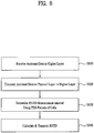
- FIG. 8 is a flowchart showing a positioning method of a UE according to an exemplary embodiment of the present invention.
- a higher layer of a UE receives assistant data from a location server (step S810).
- the assistant data may include information about a reference cell and/or at least one neighbor cell, necessary for the UE to calculate an RSTD.
- the higher layer Upon receiving the assistant data, the higher layer transmits the assistant data to a physical layer (step S820).
- the physical layer determines an RSTD measurement interval using PRS periods of a plurality of cells indicated by the assistant data (step S830).
- an RSTD is calculated and the RSTD is transmitted to the location server (step S840).
- step S810 in which the UE receives assistant data through the higher layer will be described.
- the UE may request, through a BS, that a location server transmit assistant data and receive the assistant data from the location server.
- FIG. 9 is a diagram showing a process of requesting and receiving assistant data in a UE.
- the UE transmits an assistant data request (RequestAssistanceData) message to a location server through a BS.
- the location server transmits an assistant data provide (ProvideAssistanceData) message including the assistant data to the UE.
- the location server may transmit an additional assistant data provide message including additional assistant data to the UE.
- the assistant data provide message finally transmitted by the location server includes an end transaction indicator indicating that the message is a final message.
- the location server may transmit an assistant data provide message to the UE without a request of the UE.
- FIG. 10 is a diagram showing a process of transmitting location information.
- the location server transmits a location information request (RequestLocationInformation) message to the UE in order to request location information.
- a necessary type of location information or additional assistant Quality of Service (QoS) may be indicated.
- the UE transmits a location information provide (ProvideLocationInformation) message to the location server in order to transmit location information.
- the transmitted location information should match or be a subset of location information requested in a previous step unless the location server explicitly permits the UE to transmit additional location information.
- the UE Upon receiving an additional location information request message, the UE transmits an additional location information provide (ProvideLocationInformation) message to the location server in order to transmit location information.
- the transmitted location information should match with or be a subset of location information requested in a previous step unless the location server explicitly permits the UE to transmit additional location information.
- a finally transmitted provide message includes an end transaction indicator indicating that the message is a final message.
- Table 1 shows OTDOA assistant data included in the ProvideAssistanceData message.
- the OTDOA assistant data includes OTDOA reference cell information (otdoa-ReferenceCellInfo) and OTDOA neighbor cell information (otdoa-NeighbourCellInfo).
- Table 2 shows the otdoa-ReferenceCellInfo.
- the otdoa-ReferenceCellInfo includes information about a reference cell. As shown in Table 2, otdoa-ReferenceCellInfo includes a physical cell ID (physCellId), antenna port configuration (antennaPortConfig), a cyclic prefix length (cpLength), and PRS information (prsInfo).
- otdoa-ReferenceCellInfo includes a physical cell ID (physCellId), antenna port configuration (antennaPortConfig), a cyclic prefix length (cpLength), and PRS information (prsInfo).
- the physCellId indicates a physical cell ID of a reference cell
- the antennaPortConfig indicates whether a reference cell uses at least one antenna port or 4 antenna ports for a cell-specific reference signal.
- the cpLength indicates the length of a CP used when a reference cell transmits a PRS.
- the prsInfo will be described in detail with reference to Table 3. Table 3 shows the prsInfo.
- the prsInfo includes a PRS bandwidth (prs-Bandwidth), a PRS configuration index (prs-ConfigurationIndex), a downlink frame number (numDL-Frames), and PRS muting information (prs-MutingInfo).
- the prs-Bandwidth indicates a bandwidth used to determine a PRS and the numDL-Frames indicates the number, N prs , of consecutive downlink subframes to which PRSs are allocated.
- the prs-MutingInfo indicates PRS muting configuration of a corresponding cell.
- the PRS muting configuration is defined as a periodic PRS muting sequence having a period of T PRS which is indicated by the number of PRS positioning occasions.
- the PRS positioning occasions include N prs downlink subframe.
- the prs-MutingInfo may be defined based on a System Frame Number (SFN) of a serving cell or a reference cell. If the prs-MutingInfo is defined as an SFN of a serving cell, the first bit of a PRS muting sequence corresponds to the first positioning occasion starting after a start point of a frame in which an SFN of the serving cell is 0. If the prs-MutingInfo is defined as an SFN of a reference cell, the first bit of a PRS muting sequence corresponds to the first positioning occasion starting after a start point of a frame in which an SFN of the reference cell is 0.
- SFN System Frame Number
- the prs-ConfigurationIndex indicates a PRS configuration index.
- the PRS configuration index I PRS represents information about the time when a PRS is transmitted.
- Table 4 shows the otdoa-NeighbourCellInfo.
- the otdoa-NeighbourCellInfo includes at least one OTDOA neighbor cell information element (OTDOA-NeighbourCellInfoElement).
- OTDOA-NeighbourCellInfoElement included in the otdoa-NeighbourCellInfo may be arranged in a descending order according to priority of neighbouring cells for RSTD measurement of a UE.
- the first OTDOA-NeighbourCellInfoElement included in the otdoa-NeighbourCellInfo may be OTDOA-NeighbourCellInfoElement of a neighbouring cell having the highest priority for RSTD measurement of a UE.
- Each OTDOA-NeighbourCellInfoElement includes a physical cell identity (physCellId), a cyclic prefix length (cpLength), PRS information (prsInfo), antenna port configuration (antennaPortConfig), a slot number offset (slotNumberOffset), a PRS subframe offset (prs-SubframeOffset), an expected RSTD value (expectedRSTD), and uncertainty of the expected RSTD value (expectedRSTD-Uncertainty).
- the physCellId indicates a physical cell ID of a neighbor cell
- the antennaPortConfig indicates whether a neighbor cell uses one (or two) antenna ports or 4 antenna ports, for a cell-specific reference signal
- the cpLength indicates the length of a CP of a PRS of a neighbor cell.
- the prsInfo indicates information about PRS configuration of a neighbor cell.
- the prsInfo included in the OTDOA-NeighbourCellInfoElement has the same format as the prsInfo included in otdoa-ReferenceCellInfo shown in FIG. 3 .
- the prsInfo includes prs-Bandwidth, prs-ConfigurationIndex, numDL-Frames, and prs-MutingInfo.
- the prs-Bandwidth indicates a bandwidth used to transmit a PRS of a neighbor cell
- the numDL-Frames indicates the number, N prs , of consecutive downlink subframes to which PRSs of neighbor cells are allocated
- the prs-MutingInfo indicates PRS muting configuration of a neighbor cell
- the prs-ConfigurationIndex indicates a PRS configuration index of a neighbor cell.
- the slotNumberOffset indicates a slot number offset of a reference cell and a neighbor cell.
- the slotNumberOffset represents an offset from a start point of a specific radio frame of a reference cell to a start point of a radio frame of a neighbor cell which first appears after the specific radio frame.
- the slotNumberOffset is expressed by the number of slots. If a slot timing of a neighbor cell is the same as that of a reference cell, a slotNumberOffset field may be omitted.
- the prs-SubframeOffset indicates an offset of a first PRS subframe of a reference cell in a reference subcarrier frequency and a first PRS subframe of a PRS burst of a neighbor cell, which first appears after the first PRS subframe of the reference cell, in another subcarrier frequency.
- the prs-SubframeOffset is expressed by the number of subframes.
- the expectedRSTD indicates an RSTD value which is expected to be measured by a UE. If T s is 1/(15000 ⁇ 2048) seconds, resolution of the expectedRSTD is 3T s .
- the expectedRSTD-Uncertainty indicates uncertainty of the expectedRSTD value. Namely, expectedRSTD-Uncertainty indicates an error range of the expectedRSTD value. Uncertainty of the expectedRSTD value is associated with UE position estimation of a location server. The expectedRSTD-Uncertainty defines a search window of a UE as shown in Equation 4 and resolution of the expectedRSTD-Uncertainty is 3T s . expectedRSTD ⁇ expectedRSTD _ Uncertainty ⁇ measuredRSTD ⁇ expectedRSTD + expectedRSTD _ Uncertainty
- the higher layer of the UE upon receiving the assistant data, transmits the assistant data to a physical layer (step S820).
- the physical layer determines an RSTD measurement interval using PRS periods of a plurality of cells indicated by the assistant data (step S830).
- Table 5 shows a PRS period T PRS and a PRS subframe offset ⁇ PRS according to a PRS configuration index I PRS .
- PRS configuration Index (I PRS ) PRS periodicity T PRS (subframes) PRS subframe offset ⁇ PRS (subframes) 0 - 159 160 I PRS 160 - 479 320 I PRS - 160 480 - 1119 640 I PRS - 480 1120-2399 1280 I PRS - 1120 2400-4095 Reserved
- the PRS configuration index is received by a physical layer from a higher layer.
- a PRS is transmitted only in configured subframes and transmitted only in N PRS consecutive downlink subframes.
- N PRS is configured in a higher layer.
- n f denotes an SFN and n s denotes a slot number. That is, upon receiving the ProvideAssistanceData message, a UE can discern PRS information using the prs-ConfigurationIndex of at least one cell included in the ProvideAssistanceData message.
- a UE can receive and measure an RSTD.
- n is at least 16 cells including a reference cell in a frequency band and the reference cell satisfies T RSTD ms given by the following equation.
- T RSTD T PRS ⁇ M ⁇ 1 + ⁇ ms
- T RSTD denotes a total time necessary for search and measurement in at least n cells
- T PRS denotes a cell-specific positioning subframe configuration period
- M denotes the number of PRS positioning occasions
- ⁇ 160 ⁇ ⁇ n M ⁇ ms denotes a measurement time for one PRS positioning occasion and includes a sampling time and a processing time.
- Table 6 shows the number, M, of positioning occasions.
- Positioning subframe configuration period T PRS Number of PRS positioning.occasions M f1 (intra-frequency) f1 and f2 (inter-frequency) 160 ms 16 32 >160 ms 8 16
- an RSTD measured within T RSTD can be transmitted (step S840).
- FIG. 11 is a diagram showing a process of transmitting assistant data to a physical layer and determining an RSTD measurement interval using a PRS period.
- step 1110 if assistant data is received by higher layers (step 1110), the higher layers transmit the assistant data to physical layers (step 1120).
- a PRS period T PRS is determined according to the assistant data (step 1130) and an RSTD measurement interval T RSTD is determined according to the determined T PRS (step 1140).
- a PRS received from each cell is measured based on the RSTD measurement interval T RSTD and a TOA is calculated so that an RSTD may be reported to a location server.
- a UE calculates the T RSTD using the above-described method, a plurality of cells (e.g. femto, pico and macro cells) may have different PRS transmission periods. Then, it is uncertain when the UE should perform report and measurement. This will be described with reference to FIG. 12 .
- a plurality of cells e.g. femto, pico and macro cells
- FIG. 12 is a diagram showing a process of determining positioning measurement intervals when a PRS period varies according to each cell.
- a UE receives a PRS from a reference cell, a cell A, and a cell B.
- T RSTD RSTD measurement interval
- a T RSTD of the reference cell having the second longest T PRS is calculated and a T RSTD of the cell A is calculated as the longest value.
- the UE reports the measured RSTD. Namely, the UE should repeatedly report the RSTD so that performance deterioration may occur.
- a positioning method in which a T RSTD is determined using a PRS period (T PRS ) of a predetermined condition among PRS periods (T PRS ) of a plurality of cells and a UE can efficiently perform measurement and reporting using the determined T RSTD .
- FIG. 13 is a flowchart showing a process of applying a measurement interval using the longest PRS period according to an exemplary embodiment of the present invention.
- Steps S1310, S1320, and S1350 shown in FIG. 13 are similar to steps S810, S820, and S840, respectively and therefore a description thereof is omitted.
- OTDOA related data (e.g. assistant data), which is received by a higher layer and is transmitted to a physical layer, includes a plurality of cell IDs and PRS configuration information of corresponding cells.
- the physical layer may calculate a specific PRS period of a plurality of cells by using the PRS configuration information included in the data.
- a T RSTD is calculated using each T PRS as described with reference to FIG. 12 .
- a T RSTD is calculated using a T PRS having the largest value among cell-specific PRS transmission periods (steps S1330 and S1340).
- T RSTD T PRS ⁇ ( M -1)+ ⁇ is used as described above.
- T RSTD denotes the length of an RSTD measurement interval
- T PRS denotes the largest value of the plurality of cell-specific PRS transmission periods
- M denotes the number of PRS positioning occasions
- ⁇ denotes a measurement time for one PRS positioning occasion.
- the T RSTD is calculated using the longest T PRS of the cell-specific PRS periods. If the calculated T RSTD has elapsed, a UE reports measured RSTDs for a plurality of cells. Since the calculated T RSTD is always greater than T RSTD calculated using PRS transmission periods of other cells, measurement accuracy can be maintained and a plurality of positioning related information can be provided to a location server through a single reporting.
- FIG. 14 To describe the present invention in more detail, reference is made to FIG. 14 .
- FIG. 14 is a diagram showing a process of applying an RSTD measurement interval using the longest PRS period according to an exemplary embodiment of the present invention.
- a UE receives PRSs from a reference cell, a cell A, and a cell B and measurement intervals T RSTD of the respective cells are increased in order of the cell B, the reference cell, and the cell A.
- RSTDs are calculated for PRS values received from a plurality of cells based on a T RSTD of the cell A having the largest value among T RSTD calculated based on PRS periods of the respective cells, and the calculated RSTDs are transmitted to a location server. Since the T RSTD of the cell A is longer than a T RSTD of the reference cell or a T RSTD of the cell B, the T RSTD of the other cells is guaranteed and measurement accuracy is ensured. Further, since a T RSTD of one cell (e.g., cell A) is used without reporting RSTDs calculated according to T RSTD of the respective cells, a repeated reporting execution operation of a UE is simplified.
- an RSTD measurement interval may be started from a subframe having the nearest PRS positioning occasion after assistant data is transmitted to a physical layer.
- location information reporting of a UE is performed after a T RSTD calculated to ensure signal accuracy has elapsed. However, if a preset signal strength condition is satisfied, the reporting may be performed even before T RSTD has elapsed.
- a UE may provide RSTD measurement information for one or more cells satisfying a preset condition within a T RSTD determined based on the longest T PRS to a location server.
- an RSTD value measured for at least one cell having a T RSTD within the T RSTD of the reference cell may be reported to the location server.
- FIG. 15 is a diagram showing a process of applying an RSTD measurement interval using a PRS period of a reference cell and the longest PRS period according to an exemplary embodiment of the present invention.
- T RSTD is applied by a preset reference.
- a UE basically provides RSTD measurement information for a plurality of cells based on a T RSTD determined using the longest T PRS to a location server.
- a T RSTD determined using a T PRS of the reference cell may have elapsed.
- the UE transmits a determined RSTD of at least one cell having a T RSTD within the T RSTD of the reference cell to the location server. Therefore, it may be possible to transmit, to the location server, RSTD values of a plurality of cells using the T RSTD determined using the longest T PRS and the T RSTD determined using the T PRS of the reference cell.
- location information of a UE is reported after a T RSTD calculated to ensure signal accuracy has elapsed. However, if a preset signal strength condition is satisfied, the reporting may be performed even before the T RSTD has elapsed.
- a condition that the RSTD measurement information is reported in a T RSTD of each cell after a T RSTD of the reference cell has elapsed may be set.
- the UE simultaneously reports RSTD values of a plurality of cells based on a T RSTD determined using the longest T PRS .
- the UE may provide RSTD measurement information about the reference cell to the location server and thereafter if a T RSTD of each cell longer than the T RSTD of the reference cell has elapsed, the UE may provide RSTD measurement information about the cell to the location server.
- location information report of a UE is performed after a T RSTD calculated to ensure signal accuracy has elapsed. However, if a preset signal strength condition is satisfied, the reporting may be performed even before the T RSTD has elapsed.
- the UE may provide RSTD measurement information for a plurality of cells using a T RSTD determined based on a T PRS of a reference cell to the location server.
- the UE may report a plurality of RSTD values according to a T RSTD determined based on a T PRS of the reference cell instead of the longest T RRS .
- FIG. 16 is a diagram showing a process of applying a measurement interval using a PRS period of a reference cell according to another exemplary embodiment of the present invention.
- a T RSTD of the reference cell is used. Namely, a UE may transmit calculated RSTD values of the respective cells to a location server after the T RSTD of the reference cell has elapsed.
- the reference cell may provide a reference value compared with values of other cells. If the UE performs reporting based on one T RSTD , a reporting time can be clearly determined and deterioration in an error or function of the UE can be prevented.
- location information of a UE is reported after a T RSTD calculated to ensure signal accuracy has elapsed. However, if a preset signal strength condition is satisfied, the reporting may be performed even before the T RSTD has elapsed.
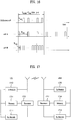
- FIG. 17 is a diagram illustrating a transmitter and a receiver through which exemplary embodiments of the present invention can be implemented.
- Each of the transmitter and receiver may be a UE or a BS and the UE and BS may communicate with each other through a location server.
- the transmitter and receiver include antennas for transmitting and receiving information, data, signals, and/or messages, transmission (Tx) modules 1712 and 1732 for transmitting messages by controlling the antennas, reception (Rx) modules 1711 and 1731 for receiving messages by controlling the antenna, memories 1714 and 1734 for storing communication related information, and processors 1713 and 1733 for controlling the TX modules, Rx modules and memories, respectively.
- Tx transmission
- Rx reception
- processors 1713 and 1733 for controlling the TX modules, Rx modules and memories, respectively.
- the antennas transmit signals generated from the Tx modules 1712 and 1732 to the outside, or transfer radio signals received from the outside to the Rx modules 1711 and 1731. If a Multiple Input Multiple Output (MIMO) function is supported, the transmitter and receiver may include two or more antennas.
- MIMO Multiple Input Multiple Output
- the processors 1713 and 1733 generally control overall operations of the transmitter or receiver. Especially, the processors 1713 and 1733 may carry out a control function for performing the embodiments of the present invention, a MAC frame variable control function based on service characteristics and a propagation environment, a handover function, and an authentication and encryption function. Each of the processors 1713 and 1733 may include an encryption module for encrypting various messages and a timer module for controlling the transmission and reception of various messages.
- the processor 1713 of the UE receives PRSs from a reference cell and a plurality of neighbor cells using system information received from the BS and measures RSTDs between the reference cell and the plurality of neighbor cells.
- the processor 1713 may calculate a T RSTD using a T PRS having the greatest value among cell-specific transmission periods.
- T RSTD T PRS ⁇ ( M -1)+ ⁇ .
- T RSTD denotes the length of an RSTD measurement interval
- T PRS denotes the largest value of the plurality of cell-specific PRS periods
- M denotes the number of positioning occasions
- ⁇ denotes a measurement time for one PRS positioning occasion.
- the processor 1733 of the BS determines the location of the UE using RSTDs received from the UE.
- the TX modules 1712 and 1732 perform predetermined coding and modulation upon signals and/or data, which are scheduled by the processors and transmitted to the outside, and then transfer the modulated signals and/or data to the antennas.
- the Tx module 1712 of the UE transmits RSTDs between the reference cell and the plurality of neighbor cells to the location server.
- the Tx module 1732 of the BS transmits system information including information about the reference cell and the plurality of cells to the UE.
- the Rx modules 1711 and 1731 decode and demodulate upon radio received from the outside through the antennas and transfer the demodulated signals to the processors 1713 and 1733.
- the Rx module 1711 of the UE receives system information including information about a reference cell and a plurality of neighboring cells from a location server.
- the system information includes cells in which a UE can obtain an SFN as the reference cell or the plurality of neighboring cells.
- the Rx module 1731 of the BS receives RSTDs between the reference cell and the plurality of neighboring cells from the UE.
- the memories 1714 and 1734 may store programs required for signal processing and control of the processors and temporarily store input and output data (in the case of the UE, uplink grant allocated from the BS, system information, a STation IDentifier (STID), a Follow IDentifier (FID), action time, area allocation information, frame offset information etc.).
- STation IDentifier STation IDentifier
- FID Follow IDentifier
- the memories 1714 and 1734 may include at least one type of storage medium among a flash memory-type storage medium, a hard disk-type storage medium, a multimedia card micro-type storage medium, a card-type memory (e.g. a Secure Digital (SD) or eXtreme Digital (XS) memory), a Random Access Memory (RAM), a Static Random Access Memory (SRAM), a Read-Only Memory (ROM), an Electrically Erasable Programmable Read-Only Memory (EEPROM), a Programmable Read-Only Memory (PROM), a magnetic memory, a magnetic disc, and an optical disk.
- SD Secure Digital
- XS eXtreme Digital
- RAM Random Access Memory
- SRAM Static Random Access Memory
- ROM Read-Only Memory
- EEPROM Electrically Erasable Programmable Read-Only Memory
- PROM Programmable Read-Only Memory
- the embodiments of the present invention can be applied to various wireless access systems.
- the various wireless access systems include 3GPP(3rd Generation Partnership Project) system, 3GPP2 system and/or IEEE 802.xx (Institute of Electrical and Electronic Engineers 802) system.
- the embodiments of the present invention can be applied to all technical fields to which the various access systems are applied, as well as the various access systems.
Landscapes
- Physics & Mathematics (AREA)
- Engineering & Computer Science (AREA)
- General Physics & Mathematics (AREA)
- Radar, Positioning & Navigation (AREA)
- Remote Sensing (AREA)
- Mobile Radio Communication Systems (AREA)
- Position Fixing By Use Of Radio Waves (AREA)
Claims (12)
- Verfahren, das von einem Endgerät, UE, durchgeführt wird, zum Ermitteln eines Bezugssignalzeitdifferenz-Messintervalls, RSTD-Messintervalls, für eine Vielzahl von Zellen am Endgerät in einem drahtlosen Kommunikationssystem, umfassend:Erfassen einer Nachricht, die mit Observed Time Difference of Arrival, OTDOA, verbundene Daten enthält, in einer höheren Schicht, wobei die mit OTDOA verbundenen Daten Zellenkennungen der Mehrzahl von Zellen und eine Positionierungsbezugssignal-Konfigurationsinformation, PRS-Konfigurationsinformation, der Vielzahl von Zellen enthält;Liefern der mit OTDOA verbundenen Daten an eine Bitübertragungsschicht von der höheren Schicht; undErmitteln des RSTD-Messintervalls für die Mehrzahl von Zellen durch die folgende Gleichung unter Verwendung einer Mehrzahl von zellenspezifischen PRS-Sendeperioden, TPRS, die mit der Mehrzahl von Zellen assoziiert sind, die unter Verwendung der PRS-Konfigurationsinformation der Mehrzahl von Zellen erhalten wurden:
 wobei TRSTD die Länge des RSTD-Messintervalls bezeichnet, TPRS max den größten Wert der Mehrzahl von zellenspezifischen PRS-Sendeperioden TPRS bezeichnet, M die Anzahl von PRS-Positionierungsereignissen im RSTD-Messintervall bezeichnet und Δ eine Messzeit für ein PRS-Positionierungsereignis anzeigt, das mit dem größten Wert TPRS max assoziiert ist,Melden von RSTD-Messungen für die Mehrzahl von Zellen unter Verwendung der ermittelten TRSTD an ein erweitertes mobiles Versorgungsstandortzentrum.
 - Verfahren nach Anspruch 1, wobei das RSTD-Messintervall von einem Subrahmen mit dem nächsten PRS-Positionierungsereignis beginnt, nachdem die mit OTDOA verbundenen Daten an die Bitübertragungsschicht gesendet wurden.
- Verfahren nach Anspruch 1, ferner umfassend ein Bereitstellen einer RSTD-Messinformation an einen Standortserver, nachdem das RSTD-Messintervall verstrichen ist.
- Verfahren nach Anspruch 3, ferner umfassend ein Bereitstellen einer RSTD-Messinformation über eine oder mehrere Zellen, die eine vorbestimmte Bedingung innerhalb des RSTD-Messintervalls erfüllen, an den Standortserver.
- Verfahren nach Anspruch 3, ferner umfassend ein Bereitstellen einer RSTD-Messinformation über eine Bezugzelle an den Standortserver, nachdem ein Messintervall, das unter Verwendung einer PRS-Periode der Bezugszelle ermittelt wurde, innerhalb des RSTD-Messintervalls abgelaufen ist.
- Verfahren nach Anspruch 1, wobei die Nachricht, die die mit OTDOA verbundenen Daten enthält, über eine Versorgungsbasisstation von einem Standortserver empfangen wird.
- Endgerät (1712), das ausgelegt ist, ein Bezugssignalzeitdifferenz-Messintervall, RSTD-Messintervall, für eine Vielzahl von Zellen am Endgerät in einem drahtlosen Kommunikationssystem zu ermitteln, umfassend:eine Funkfrequenzeinheit, RF-Einheit; undeinen Prozessor;wobei der Prozessor (1713) ausgelegt ist, eine Nachricht, die mit Observed Time Difference of Arrival, OTDOA, verbundene Daten enthält, in einer höheren Schicht zu erfassen, wobei die mit OTDOA verbundenen Daten Zellenkennungen der Mehrzahl von Zellen und eine Positionierungsbezugssignal-Konfigurationsinformation, PRS-Konfigurationsinformation, der Vielzahl von Zellen enthält, die mit OTDOA verbundenen Daten von der höheren Schicht an eine Bitübertragungsschicht zu liefern
und das RSTD-Messintervall für die Mehrzahl von Zellen durch die folgende Gleichung unter Verwendung einer Mehrzahl von zellenspezifischen PRS-Sendeperioden, TPRS, zu ermitteln, die mit der Mehrzahl von Zellen assoziiert sind, die unter Verwendung der PRS-Konfigurationsinformation der Mehrzahl von Zellen erhalten wurden: wobei TRSTD die Länge des RSTD-Messintervalls bezeichnet, TPRS max den größten Wert der Mehrzahl von zellenspezifischen PRS-Sendeperioden TPRS bezeichnet, M die Anzahl von PRS-Positionierungsereignissen im RSTD-Messintervall bezeichnet und Δ eine Messzeit für ein PRS-Positionierungsereignis anzeigt, das mit dem größten Wert TPRS max assoziiert ist,RSTD-Messungen für die Mehrzahl von Zellen unter Verwendung der ermittelten TRSTD an ein erweitertes mobiles Versorgungsstandortzentrum zu melden.
 - Endgerät nach Anspruch 7, wobei das RSTD-Messintervall von einem Subrahmen mit dem nächsten PRS-Positionierungsereignis beginnt, nachdem die mit OTDOA verbundenen Daten an die Bitübertragungsschicht gesendet wurden.
- Endgerät nach Anspruch 7, wobei der Prozessor ausgelegt ist, einem Standortserver eine RSTD-Messinformation bereitzustellen, nachdem das RSTD-Messintervall verstrichen ist.
- Endgerät nach Anspruch 9, wobei der Prozessor ausgelegt ist, dem Standortserver eine RSTD-Messinformation über eine oder mehrere Zellen bereitzustellen, die eine vorbestimmte Bedingung innerhalb des RSTD-Messintervalls erfüllen.
- Endgerät nach Anspruch 9, wobei der Prozessor ausgelegt ist, dem Standortserver eine RSTD-Messinformation über eine Bezugzelle bereitzustellen, nachdem ein Messintervall, das unter Verwendung einer PRS-Periode der Bezugszelle ermittelt wurde, innerhalb des RSTD-Messintervalls abgelaufen ist.
- Endgerät nach Anspruch 7, wobei die Nachricht, die die mit OTDOA verbundenen Daten enthält, über eine Versorgungsbasisstation von einem Standortserver empfangen wird.
Applications Claiming Priority (3)
| Application Number | Priority Date | Filing Date | Title |
|---|---|---|---|
| US41487410P | 2010-11-17 | 2010-11-17 | |
| KR1020110036362A KR20120053941A (ko) | 2010-11-17 | 2011-04-19 | 무선 통신 시스템에서 위치 결정 방법 및 장치 |
| PCT/KR2011/004142 WO2012067328A1 (en) | 2010-11-17 | 2011-06-07 | Positioning method and apparatus in wireless communication system |
Publications (3)
| Publication Number | Publication Date |
|---|---|
| EP2641103A1 EP2641103A1 (de) | 2013-09-25 |
| EP2641103A4 EP2641103A4 (de) | 2017-08-02 |
| EP2641103B1 true EP2641103B1 (de) | 2020-03-11 |
Family
ID=46270002
Family Applications (1)
| Application Number | Title | Priority Date | Filing Date |
|---|---|---|---|
| EP11840789.9A Active EP2641103B1 (de) | 2010-11-17 | 2011-06-07 | Positionierungsverfahren und vorrichtung in drahtlosen kommunikationssystemen |
Country Status (7)
| Country | Link |
|---|---|
| US (1) | US9201134B2 (de) |
| EP (1) | EP2641103B1 (de) |
| JP (1) | JP2014503799A (de) |
| KR (1) | KR20120053941A (de) |
| CN (1) | CN103221838A (de) |
| CA (1) | CA2818115C (de) |
| WO (1) | WO2012067328A1 (de) |
Families Citing this family (35)
| Publication number | Priority date | Publication date | Assignee | Title |
|---|---|---|---|---|
| US9645225B2 (en) * | 2008-11-21 | 2017-05-09 | Qualcomm Incorporated | Network-centric determination of node processing delay |
| US9279879B2 (en) | 2009-06-26 | 2016-03-08 | Qualcomm Incorporated | Positioning in the presence of passive distributed elements |
| CN103329604B (zh) | 2010-12-14 | 2017-04-05 | Lg电子株式会社 | 用于测量观测到达时间差otdoa的方法和装置 |
| US9271256B2 (en) * | 2011-08-30 | 2016-02-23 | Qualcomm Incorporated | Verifying generic broadcast of location assistance data |
| JP2014011539A (ja) * | 2012-06-28 | 2014-01-20 | Sharp Corp | 移動局装置、基地局装置、通信システム、セル選択方法および集積回路 |
| CN103686992A (zh) * | 2012-09-07 | 2014-03-26 | 华为技术有限公司 | 一种信号到达时间测量方法及ue |
| US9651653B2 (en) | 2012-12-24 | 2017-05-16 | Qualcomm Incorporated | Positioning reference signal (PRS) generation for multiple transmit antenna systems |
| CN104159241B (zh) * | 2013-05-13 | 2017-12-22 | 华为技术有限公司 | 一种测量小区的确定方法及装置 |
| US9313698B2 (en) * | 2013-10-11 | 2016-04-12 | Blackberry Limited | Method and apparatus for handover in heterogeneous cellular networks |
| CN104635206B (zh) * | 2013-11-14 | 2018-10-23 | 中兴通讯股份有限公司 | 一种无线定位的方法及装置 |
| CN106461748A (zh) | 2014-06-25 | 2017-02-22 | 英特尔公司 | 长期演进协作多点通信系统中的用户设备定位 |
| WO2016032308A1 (ko) * | 2014-08-29 | 2016-03-03 | 엘지전자 주식회사 | 무선 통신 시스템에서 otdoa 관련 동작 수행 방법 |
| US9686064B2 (en) | 2015-01-21 | 2017-06-20 | Intel IP Corporation | Devices and methods for HARQ-ACK feedback scheme on PUSCH in wireless communication systems |
| CN107113569B9 (zh) * | 2015-01-26 | 2021-06-04 | 苹果公司 | 提高水平和垂直定位准确性的设备和方法 |
| EP3250937B1 (de) * | 2015-01-26 | 2020-08-05 | Intel IP Corporation | Otdoa (observed time difference of arrival)-ortungsverbesserung durch verwendung von heterogenen referenzsignalen |
| EP3264838A4 (de) | 2015-02-27 | 2018-11-07 | LG Electronics Inc. | Verfahren zur durchführung operationen im zusammenhang mit otdoa in einem drahtloskommunikationssystem |
| US10111213B2 (en) * | 2015-03-26 | 2018-10-23 | Lg Electronics Inc. | Method for reporting measurement result for determining position in wireless communication system, and device therefor |
| US9482742B1 (en) | 2015-05-12 | 2016-11-01 | Qualcomm Incorporated | Positioning reference signal (PRS) generation for multiple transmit antenna systems |
| CN106304328B (zh) * | 2015-06-01 | 2020-10-16 | 索尼公司 | 无线通信系统中的电子设备和无线通信方法 |
| CN107925496B (zh) | 2015-08-25 | 2019-09-17 | Lg 电子株式会社 | 在无线通信系统中测量用于定位的参考信号的方法及设备 |
| CN105652239B (zh) * | 2015-12-23 | 2017-11-28 | 深圳市国华光电研究院 | 一种自适应的高精度室内定位方法和系统 |
| WO2018030681A1 (ko) | 2016-08-08 | 2018-02-15 | 엘지전자 주식회사 | Nprs 전송 방법 및 이를 위한 장치 |
| US9918264B1 (en) * | 2016-09-09 | 2018-03-13 | Qualcomm Incorporated | Reporting of information before a scheduled time |
| US10120060B2 (en) | 2017-02-02 | 2018-11-06 | Qualcomm Incorporated | Location determination using user equipment preconfigured with positioning reference signal information |
| US10420063B2 (en) * | 2017-02-02 | 2019-09-17 | Qualcomm Incorporated | On-demand user equipment positioning |
| JP6971050B2 (ja) * | 2017-04-14 | 2021-11-24 | シスメックス株式会社 | 位置管理方法、位置管理システム、位置管理プログラムおよび携帯通信機器 |
| US10383081B2 (en) * | 2017-05-05 | 2019-08-13 | Qualcomm Incorporated | Methods and systems for positioning of a mobile device using broadcast of assistance data |
| WO2019157708A1 (zh) * | 2018-02-14 | 2019-08-22 | 华为技术有限公司 | 通信方法、设备及系统 |
| US11356804B2 (en) | 2018-02-25 | 2022-06-07 | Qualcomm Incorporated | Systems and methods for efficiently supporting broadcast of location assistance data in a wireless network |
| US11191056B2 (en) | 2018-08-08 | 2021-11-30 | Qualcomm Incorporated | Systems and methods for validity time and change notification of broadcast location assistance data |
| WO2020191646A1 (en) * | 2019-03-27 | 2020-10-01 | Nokia Shanghai Bell Co., Ltd. | Wireless positioning measurement |
| CN112203213B (zh) * | 2019-06-19 | 2023-03-28 | 中国移动通信有限公司研究院 | 一种信息处理方法、装置、终端及存储介质 |
| US11375340B2 (en) * | 2019-08-09 | 2022-06-28 | Kt Corporation | Apparatus and method for performing positioning |
| US11736934B2 (en) * | 2020-04-28 | 2023-08-22 | Qualcomm Incorporated | Minimum positioning reference signal (PRS) processing when measurement gaps are not configured |
| WO2023010571A1 (zh) * | 2021-08-06 | 2023-02-09 | 北京小米移动软件有限公司 | 一种定位测量的方法及其装置 |
Family Cites Families (24)
| Publication number | Priority date | Publication date | Assignee | Title |
|---|---|---|---|---|
| US9137771B2 (en) * | 2004-04-02 | 2015-09-15 | Qualcomm Incorporated | Methods and apparatuses for beacon assisted position determination systems |
| KR100602189B1 (ko) * | 2004-07-07 | 2006-07-19 | 삼성전자주식회사 | 프레임 및 심볼 시간동기 검출장치 및 검출방법 |
| JP2007006229A (ja) * | 2005-06-24 | 2007-01-11 | Matsushita Electric Ind Co Ltd | 通信端末装置、ネットワーク装置及び位置測定方法 |
| KR20080085653A (ko) * | 2007-03-19 | 2008-09-24 | 엘지전자 주식회사 | 상향링크 기준신호 전송방법 |
| US8599819B2 (en) | 2007-06-19 | 2013-12-03 | Lg Electronics Inc. | Method of transmitting sounding reference signal |
| EP2180629B1 (de) * | 2007-08-14 | 2017-11-29 | LG Electronics Inc. | Verfahren zur Gewinnung von Ressourcenbereichsinformation für den PHICH sowie Verfahren zum Empfang des PDCCH |
| KR101405974B1 (ko) * | 2007-08-16 | 2014-06-27 | 엘지전자 주식회사 | 다중입력 다중출력 시스템에서 코드워드를 전송하는 방법 |
| KR101507785B1 (ko) * | 2007-08-16 | 2015-04-03 | 엘지전자 주식회사 | 다중 입출력 시스템에서, 채널품질정보를 송신하는 방법 |
| KR101738162B1 (ko) * | 2009-04-10 | 2017-05-22 | 엘지전자 주식회사 | 무선 통신 시스템에서 포지셔닝 참조 신호 전송 방법 및 장치 |
| KR101644881B1 (ko) * | 2009-04-10 | 2016-08-03 | 엘지전자 주식회사 | 무선 이동 통신 시스템에 있어서, 사용자 기기의 위치를 결정하기 위한 방법 및 이를 수행하기 위한 장치 |
| EP2425559B1 (de) * | 2009-04-27 | 2017-05-17 | Telefonaktiebolaget LM Ericsson (publ) | Verfahren und anordnungen in einem drahtlosen kommunikationssystem |
| US9002354B2 (en) | 2009-06-12 | 2015-04-07 | Google Technology Holdings, LLC | Interference control, SINR optimization and signaling enhancements to improve the performance of OTDOA measurements |
| US8462736B2 (en) * | 2009-06-19 | 2013-06-11 | Telefonaktiebolaget L M Ericsson (Publ) | Telecommunications method and apparatus for facilitating positioning measurements |
| EP3206447A1 (de) | 2009-06-24 | 2017-08-16 | IDTP Holdings, Inc. | Verfahren und anordnungen in einem telekommunikationssystem zur ortungsunterstützung |
| US8483707B2 (en) | 2009-06-26 | 2013-07-09 | Motorola Mobility Llc | Wireless terminal and method for managing the receipt of position reference singals for use in determining a location |
| JP5069727B2 (ja) * | 2009-08-27 | 2012-11-07 | 株式会社エヌ・ティ・ティ・ドコモ | 無線基地局、移動局及び測定方法 |
| CN103004269B (zh) * | 2010-05-26 | 2016-06-08 | 瑞典爱立信有限公司 | 使用小区间干扰协调进行用户设备定位的方法和系统 |
| KR101191215B1 (ko) * | 2010-07-16 | 2012-10-15 | 엘지전자 주식회사 | 무선 통신 시스템에서 위치 결정 방법 및 장치 |
| US10034205B2 (en) | 2010-10-01 | 2018-07-24 | Telefonaktiebolaget Lm Ericsson (Publ) | Positioning measurements and carrier switching in multi-carrier wireless communication networks |
| CN103329604B (zh) | 2010-12-14 | 2017-04-05 | Lg电子株式会社 | 用于测量观测到达时间差otdoa的方法和装置 |
| JP2014511477A (ja) * | 2011-02-11 | 2014-05-15 | テレフオンアクチーボラゲット エル エム エリクソン(パブル) | 支援データの調整を介したネットワーク側の測位機会調整 |
| CN103609161B (zh) * | 2011-04-13 | 2018-04-20 | 瑞典爱立信有限公司 | 减少基于模式的测量的复杂性 |
| EP3091367B1 (de) * | 2011-08-03 | 2019-10-09 | PoLTE Corporation | Mehrpfadabschwächung bei einer bereichsfindung und objektverfolgung mithilfe einer hf-technologie mit reduzierter dämpfung |
| US8891393B2 (en) * | 2012-06-26 | 2014-11-18 | Polaris Wireless, Inc. | Measurement of reference signals with reduced interference |
-
2011
- 2011-04-19 KR KR1020110036362A patent/KR20120053941A/ko not_active Application Discontinuation
- 2011-06-07 EP EP11840789.9A patent/EP2641103B1/de active Active
- 2011-06-07 JP JP2013539731A patent/JP2014503799A/ja active Pending
- 2011-06-07 CA CA2818115A patent/CA2818115C/en active Active
- 2011-06-07 US US13/885,945 patent/US9201134B2/en active Active
- 2011-06-07 CN CN2011800557429A patent/CN103221838A/zh active Pending
- 2011-06-07 WO PCT/KR2011/004142 patent/WO2012067328A1/en active Application Filing
Non-Patent Citations (1)
| Title |
|---|
| None * |
Also Published As
| Publication number | Publication date |
|---|---|
| US20150323644A9 (en) | 2015-11-12 |
| KR20120053941A (ko) | 2012-05-29 |
| CN103221838A (zh) | 2013-07-24 |
| EP2641103A4 (de) | 2017-08-02 |
| US9201134B2 (en) | 2015-12-01 |
| JP2014503799A (ja) | 2014-02-13 |
| CA2818115A1 (en) | 2012-05-24 |
| WO2012067328A1 (en) | 2012-05-24 |
| US20130237247A1 (en) | 2013-09-12 |
| CA2818115C (en) | 2016-10-04 |
| EP2641103A1 (de) | 2013-09-25 |
Similar Documents
| Publication | Publication Date | Title |
|---|---|---|
| EP2641103B1 (de) | Positionierungsverfahren und vorrichtung in drahtlosen kommunikationssystemen | |
| US10660109B2 (en) | Systems and methods to support multiple configurations for positioning reference signals in a wireless network | |
| EP3785041B1 (de) | Positionierung von beobachteter time difference of arrival (otdoa) bei lizenziertem assistiertem zugang (laa) | |
| EP3785042B1 (de) | Positionierung von optimierter beobachteter time difference of arrival (otdoa) bei lizenziertem assistiertem zugang (laa) | |
| US11316633B2 (en) | Bandwidth-dependent positioning reference signal (PRS) transmission for narrowband internet of things (NB-IoT) observed time difference of arrival (OTDOA) positioning | |
| CN110855415B (zh) | 传输系统信息的方法及基站、终端和系统 | |
| US11879988B2 (en) | Method and apparatus for 5G positioning accuracy improvement in presence of phase noise | |
| US8995393B2 (en) | Methods and network nodes for signalling of complementary assistance data | |
| US9253677B2 (en) | Methods and apparatus for enhancing network positioning measurement performance by managing uncertain measurement occasions | |
| EP3515136B1 (de) | Verfahren zur durchführung von messungen für beobachtete ankunftszeitdifferenz in einem drahtloskommunikationssystem und vorrichtung dafür | |
| US20120287800A1 (en) | Radio Network Node, a Node and Methods Therein for Enabling Enhanced Cell ID Timing Measurement for Positioning of a User Equipment | |
| US20130190006A1 (en) | Methods and Systems for Enabling User Activity-Aware Positioning | |
| US20140254412A1 (en) | Method and network node in a radio communication system | |
| US20240089059A1 (en) | Method and apparatus for transmitting sounding reference signal for positioning in mobile wireless communication system |
Legal Events
| Date | Code | Title | Description |
|---|---|---|---|
| PUAI | Public reference made under article 153(3) epc to a published international application that has entered the european phase |
Free format text: ORIGINAL CODE: 0009012 |
|
| 17P | Request for examination filed |
Effective date: 20130617 |
|
| AK | Designated contracting states |
Kind code of ref document: A1 Designated state(s): AL AT BE BG CH CY CZ DE DK EE ES FI FR GB GR HR HU IE IS IT LI LT LU LV MC MK MT NL NO PL PT RO RS SE SI SK SM TR |
|
| DAX | Request for extension of the european patent (deleted) | ||
| RA4 | Supplementary search report drawn up and despatched (corrected) |
Effective date: 20170630 |
|
| RIC1 | Information provided on ipc code assigned before grant |
Ipc: G01S 5/02 20100101ALI20170626BHEP Ipc: G01S 5/10 20060101ALI20170626BHEP Ipc: G01S 5/08 20060101AFI20170626BHEP |
|
| GRAP | Despatch of communication of intention to grant a patent |
Free format text: ORIGINAL CODE: EPIDOSNIGR1 |
|
| STAA | Information on the status of an ep patent application or granted ep patent |
Free format text: STATUS: GRANT OF PATENT IS INTENDED |
|
| INTG | Intention to grant announced |
Effective date: 20190918 |
|
| GRAJ | Information related to disapproval of communication of intention to grant by the applicant or resumption of examination proceedings by the epo deleted |
Free format text: ORIGINAL CODE: EPIDOSDIGR1 |
|
| STAA | Information on the status of an ep patent application or granted ep patent |
Free format text: STATUS: REQUEST FOR EXAMINATION WAS MADE |
|
| GRAS | Grant fee paid |
Free format text: ORIGINAL CODE: EPIDOSNIGR3 |
|
| STAA | Information on the status of an ep patent application or granted ep patent |
Free format text: STATUS: GRANT OF PATENT IS INTENDED |
|
| INTC | Intention to grant announced (deleted) | ||
| GRAP | Despatch of communication of intention to grant a patent |
Free format text: ORIGINAL CODE: EPIDOSNIGR1 |
|
| INTG | Intention to grant announced |
Effective date: 20200113 |
|
| GRAA | (expected) grant |
Free format text: ORIGINAL CODE: 0009210 |
|
| STAA | Information on the status of an ep patent application or granted ep patent |
Free format text: STATUS: THE PATENT HAS BEEN GRANTED |
|
| AK | Designated contracting states |
Kind code of ref document: B1 Designated state(s): AL AT BE BG CH CY CZ DE DK EE ES FI FR GB GR HR HU IE IS IT LI LT LU LV MC MK MT NL NO PL PT RO RS SE SI SK SM TR |
|
| REG | Reference to a national code |
Ref country code: GB Ref legal event code: FG4D |
|
| REG | Reference to a national code |
Ref country code: CH Ref legal event code: EP |
|
| REG | Reference to a national code |
Ref country code: AT Ref legal event code: REF Ref document number: 1243838 Country of ref document: AT Kind code of ref document: T Effective date: 20200315 |
|
| REG | Reference to a national code |
Ref country code: DE Ref legal event code: R096 Ref document number: 602011065575 Country of ref document: DE |
|
| REG | Reference to a national code |
Ref country code: IE Ref legal event code: FG4D |
|
| PG25 | Lapsed in a contracting state [announced via postgrant information from national office to epo] |
Ref country code: RS Free format text: LAPSE BECAUSE OF FAILURE TO SUBMIT A TRANSLATION OF THE DESCRIPTION OR TO PAY THE FEE WITHIN THE PRESCRIBED TIME-LIMIT Effective date: 20200311 Ref country code: FI Free format text: LAPSE BECAUSE OF FAILURE TO SUBMIT A TRANSLATION OF THE DESCRIPTION OR TO PAY THE FEE WITHIN THE PRESCRIBED TIME-LIMIT Effective date: 20200311 Ref country code: NO Free format text: LAPSE BECAUSE OF FAILURE TO SUBMIT A TRANSLATION OF THE DESCRIPTION OR TO PAY THE FEE WITHIN THE PRESCRIBED TIME-LIMIT Effective date: 20200611 |
|
| REG | Reference to a national code |
Ref country code: NL Ref legal event code: MP Effective date: 20200311 |
|
| PG25 | Lapsed in a contracting state [announced via postgrant information from national office to epo] |
Ref country code: BG Free format text: LAPSE BECAUSE OF FAILURE TO SUBMIT A TRANSLATION OF THE DESCRIPTION OR TO PAY THE FEE WITHIN THE PRESCRIBED TIME-LIMIT Effective date: 20200611 Ref country code: HR Free format text: LAPSE BECAUSE OF FAILURE TO SUBMIT A TRANSLATION OF THE DESCRIPTION OR TO PAY THE FEE WITHIN THE PRESCRIBED TIME-LIMIT Effective date: 20200311 Ref country code: LV Free format text: LAPSE BECAUSE OF FAILURE TO SUBMIT A TRANSLATION OF THE DESCRIPTION OR TO PAY THE FEE WITHIN THE PRESCRIBED TIME-LIMIT Effective date: 20200311 Ref country code: SE Free format text: LAPSE BECAUSE OF FAILURE TO SUBMIT A TRANSLATION OF THE DESCRIPTION OR TO PAY THE FEE WITHIN THE PRESCRIBED TIME-LIMIT Effective date: 20200311 Ref country code: GR Free format text: LAPSE BECAUSE OF FAILURE TO SUBMIT A TRANSLATION OF THE DESCRIPTION OR TO PAY THE FEE WITHIN THE PRESCRIBED TIME-LIMIT Effective date: 20200612 |
|
| REG | Reference to a national code |
Ref country code: LT Ref legal event code: MG4D |
|
| PG25 | Lapsed in a contracting state [announced via postgrant information from national office to epo] |
Ref country code: NL Free format text: LAPSE BECAUSE OF FAILURE TO SUBMIT A TRANSLATION OF THE DESCRIPTION OR TO PAY THE FEE WITHIN THE PRESCRIBED TIME-LIMIT Effective date: 20200311 |
|
| PG25 | Lapsed in a contracting state [announced via postgrant information from national office to epo] |
Ref country code: SM Free format text: LAPSE BECAUSE OF FAILURE TO SUBMIT A TRANSLATION OF THE DESCRIPTION OR TO PAY THE FEE WITHIN THE PRESCRIBED TIME-LIMIT Effective date: 20200311 Ref country code: EE Free format text: LAPSE BECAUSE OF FAILURE TO SUBMIT A TRANSLATION OF THE DESCRIPTION OR TO PAY THE FEE WITHIN THE PRESCRIBED TIME-LIMIT Effective date: 20200311 Ref country code: CZ Free format text: LAPSE BECAUSE OF FAILURE TO SUBMIT A TRANSLATION OF THE DESCRIPTION OR TO PAY THE FEE WITHIN THE PRESCRIBED TIME-LIMIT Effective date: 20200311 Ref country code: IS Free format text: LAPSE BECAUSE OF FAILURE TO SUBMIT A TRANSLATION OF THE DESCRIPTION OR TO PAY THE FEE WITHIN THE PRESCRIBED TIME-LIMIT Effective date: 20200711 Ref country code: RO Free format text: LAPSE BECAUSE OF FAILURE TO SUBMIT A TRANSLATION OF THE DESCRIPTION OR TO PAY THE FEE WITHIN THE PRESCRIBED TIME-LIMIT Effective date: 20200311 Ref country code: SK Free format text: LAPSE BECAUSE OF FAILURE TO SUBMIT A TRANSLATION OF THE DESCRIPTION OR TO PAY THE FEE WITHIN THE PRESCRIBED TIME-LIMIT Effective date: 20200311 Ref country code: PT Free format text: LAPSE BECAUSE OF FAILURE TO SUBMIT A TRANSLATION OF THE DESCRIPTION OR TO PAY THE FEE WITHIN THE PRESCRIBED TIME-LIMIT Effective date: 20200805 Ref country code: LT Free format text: LAPSE BECAUSE OF FAILURE TO SUBMIT A TRANSLATION OF THE DESCRIPTION OR TO PAY THE FEE WITHIN THE PRESCRIBED TIME-LIMIT Effective date: 20200311 |
|
| REG | Reference to a national code |
Ref country code: AT Ref legal event code: MK05 Ref document number: 1243838 Country of ref document: AT Kind code of ref document: T Effective date: 20200311 |
|
| REG | Reference to a national code |
Ref country code: DE Ref legal event code: R097 Ref document number: 602011065575 Country of ref document: DE |
|
| PLBE | No opposition filed within time limit |
Free format text: ORIGINAL CODE: 0009261 |
|
| STAA | Information on the status of an ep patent application or granted ep patent |
Free format text: STATUS: NO OPPOSITION FILED WITHIN TIME LIMIT |
|
| PG25 | Lapsed in a contracting state [announced via postgrant information from national office to epo] |
Ref country code: IT Free format text: LAPSE BECAUSE OF FAILURE TO SUBMIT A TRANSLATION OF THE DESCRIPTION OR TO PAY THE FEE WITHIN THE PRESCRIBED TIME-LIMIT Effective date: 20200311 Ref country code: DK Free format text: LAPSE BECAUSE OF FAILURE TO SUBMIT A TRANSLATION OF THE DESCRIPTION OR TO PAY THE FEE WITHIN THE PRESCRIBED TIME-LIMIT Effective date: 20200311 Ref country code: AT Free format text: LAPSE BECAUSE OF FAILURE TO SUBMIT A TRANSLATION OF THE DESCRIPTION OR TO PAY THE FEE WITHIN THE PRESCRIBED TIME-LIMIT Effective date: 20200311 Ref country code: MC Free format text: LAPSE BECAUSE OF FAILURE TO SUBMIT A TRANSLATION OF THE DESCRIPTION OR TO PAY THE FEE WITHIN THE PRESCRIBED TIME-LIMIT Effective date: 20200311 Ref country code: ES Free format text: LAPSE BECAUSE OF FAILURE TO SUBMIT A TRANSLATION OF THE DESCRIPTION OR TO PAY THE FEE WITHIN THE PRESCRIBED TIME-LIMIT Effective date: 20200311 |
|
| REG | Reference to a national code |
Ref country code: CH Ref legal event code: PL |
|
| 26N | No opposition filed |
Effective date: 20201214 |
|
| PG25 | Lapsed in a contracting state [announced via postgrant information from national office to epo] |
Ref country code: SI Free format text: LAPSE BECAUSE OF FAILURE TO SUBMIT A TRANSLATION OF THE DESCRIPTION OR TO PAY THE FEE WITHIN THE PRESCRIBED TIME-LIMIT Effective date: 20200311 Ref country code: PL Free format text: LAPSE BECAUSE OF FAILURE TO SUBMIT A TRANSLATION OF THE DESCRIPTION OR TO PAY THE FEE WITHIN THE PRESCRIBED TIME-LIMIT Effective date: 20200311 |
|
| GBPC | Gb: european patent ceased through non-payment of renewal fee |
Effective date: 20200611 |
|
| PG25 | Lapsed in a contracting state [announced via postgrant information from national office to epo] |
Ref country code: LU Free format text: LAPSE BECAUSE OF NON-PAYMENT OF DUE FEES Effective date: 20200607 |
|
| REG | Reference to a national code |
Ref country code: BE Ref legal event code: MM Effective date: 20200630 |
|
| PG25 | Lapsed in a contracting state [announced via postgrant information from national office to epo] |
Ref country code: CH Free format text: LAPSE BECAUSE OF NON-PAYMENT OF DUE FEES Effective date: 20200630 Ref country code: IE Free format text: LAPSE BECAUSE OF NON-PAYMENT OF DUE FEES Effective date: 20200607 Ref country code: LI Free format text: LAPSE BECAUSE OF NON-PAYMENT OF DUE FEES Effective date: 20200630 Ref country code: GB Free format text: LAPSE BECAUSE OF NON-PAYMENT OF DUE FEES Effective date: 20200611 Ref country code: FR Free format text: LAPSE BECAUSE OF NON-PAYMENT OF DUE FEES Effective date: 20200630 |
|
| PG25 | Lapsed in a contracting state [announced via postgrant information from national office to epo] |
Ref country code: BE Free format text: LAPSE BECAUSE OF NON-PAYMENT OF DUE FEES Effective date: 20200630 |
|
| PG25 | Lapsed in a contracting state [announced via postgrant information from national office to epo] |
Ref country code: TR Free format text: LAPSE BECAUSE OF FAILURE TO SUBMIT A TRANSLATION OF THE DESCRIPTION OR TO PAY THE FEE WITHIN THE PRESCRIBED TIME-LIMIT Effective date: 20200311 Ref country code: MT Free format text: LAPSE BECAUSE OF FAILURE TO SUBMIT A TRANSLATION OF THE DESCRIPTION OR TO PAY THE FEE WITHIN THE PRESCRIBED TIME-LIMIT Effective date: 20200311 Ref country code: CY Free format text: LAPSE BECAUSE OF FAILURE TO SUBMIT A TRANSLATION OF THE DESCRIPTION OR TO PAY THE FEE WITHIN THE PRESCRIBED TIME-LIMIT Effective date: 20200311 |
|
| PG25 | Lapsed in a contracting state [announced via postgrant information from national office to epo] |
Ref country code: MK Free format text: LAPSE BECAUSE OF FAILURE TO SUBMIT A TRANSLATION OF THE DESCRIPTION OR TO PAY THE FEE WITHIN THE PRESCRIBED TIME-LIMIT Effective date: 20200311 Ref country code: AL Free format text: LAPSE BECAUSE OF FAILURE TO SUBMIT A TRANSLATION OF THE DESCRIPTION OR TO PAY THE FEE WITHIN THE PRESCRIBED TIME-LIMIT Effective date: 20200311 |
|
| PGFP | Annual fee paid to national office [announced via postgrant information from national office to epo] |
Ref country code: DE Payment date: 20230508 Year of fee payment: 13 |