EP2641007B1 - An improved seal between pipes - Google Patents
An improved seal between pipes Download PDFInfo
- Publication number
- EP2641007B1 EP2641007B1 EP10801672.6A EP10801672A EP2641007B1 EP 2641007 B1 EP2641007 B1 EP 2641007B1 EP 10801672 A EP10801672 A EP 10801672A EP 2641007 B1 EP2641007 B1 EP 2641007B1
- Authority
- EP
- European Patent Office
- Prior art keywords
- pin
- pipe
- box
- length
- ellipse
- Prior art date
- Legal status (The legal status is an assumption and is not a legal conclusion. Google has not performed a legal analysis and makes no representation as to the accuracy of the status listed.)
- Active
Links
Images

Classifications
-
- F—MECHANICAL ENGINEERING; LIGHTING; HEATING; WEAPONS; BLASTING
- F16—ENGINEERING ELEMENTS AND UNITS; GENERAL MEASURES FOR PRODUCING AND MAINTAINING EFFECTIVE FUNCTIONING OF MACHINES OR INSTALLATIONS; THERMAL INSULATION IN GENERAL
- F16L—PIPES; JOINTS OR FITTINGS FOR PIPES; SUPPORTS FOR PIPES, CABLES OR PROTECTIVE TUBING; MEANS FOR THERMAL INSULATION IN GENERAL
- F16L15/00—Screw-threaded joints; Forms of screw-threads for such joints
- F16L15/001—Screw-threaded joints; Forms of screw-threads for such joints with conical threads
- F16L15/004—Screw-threaded joints; Forms of screw-threads for such joints with conical threads with axial sealings having at least one plastically deformable sealing surface
-
- F—MECHANICAL ENGINEERING; LIGHTING; HEATING; WEAPONS; BLASTING
- F16—ENGINEERING ELEMENTS AND UNITS; GENERAL MEASURES FOR PRODUCING AND MAINTAINING EFFECTIVE FUNCTIONING OF MACHINES OR INSTALLATIONS; THERMAL INSULATION IN GENERAL
- F16L—PIPES; JOINTS OR FITTINGS FOR PIPES; SUPPORTS FOR PIPES, CABLES OR PROTECTIVE TUBING; MEANS FOR THERMAL INSULATION IN GENERAL
- F16L15/00—Screw-threaded joints; Forms of screw-threads for such joints
- F16L15/04—Screw-threaded joints; Forms of screw-threads for such joints with additional sealings
Definitions
- the present invention relates to an improved seal between two pipe sections.
- the pipe sections particularly contemplated find application in the oil and gas drilling industries.
- the joints are normally formed by screwing together two pipes, each having complementary threads pre-cut into the ends of each of the pipes: addition of further pipes to the free end continuing, to build up a string.
- a threaded coupling-sleeve is used to bridge across the ends of two pipes, but the principle remains the same.
- the profile and surface of the threaded part of the end of the pipes and the regions immediately around the threaded part towards the end of the pipe are specifically designed to co-operate together to provide the seal.
- the end of the pipe has a threaded portion cut either onto the outside of the pipe (to form a pin or male section) or into the inner surface of the pipe (to form a box or female section).
- the surface onto which the threaded portion is introduced can include a taper to assist the coupling process.
- the diameter of the pipe in the seal forming region can have been increased in comparison to that predominating along the length of the pipe, usually by cold forming, to allow a joint to be formed.
- an unthreaded section is normally left between the end of the pipe and the threaded section, which unthreaded section is often referred to as a stop-shoulder.
- a stop-shoulder On the pipe, an unthreaded section is normally left between the end of the pipe and the threaded section, which unthreaded section is often referred to as a stop-shoulder.
- the stop-shoulder on the pin is usually profiled to engage a corresponding recess on the box section to form a strong seal.
- the particular profile is normally chosen to disperse efficiently the strain experienced in the joint region of the pipe when torque is applied to form the joint between pipes and to retain the seal when the joint is in use.
- coatings can also be applied to improve the fluid-tight nature of the seals.
- a further problem encountered in the production of oil pipes lies in the production methods used to produce pipe sections which are intended for different uses within the industry. These are typically required to be made having different characteristics depending on the use to which the sections are to be put: for example tubing, casing etc.
- the present invention contemplates a pipe joint in which the sealing region is common across a wide range of pipe diameters resulting in a lowering of costs of manufacture.
- a pipe joint comprising:
- the long axis of the ellipse described by the curved sealing surface on the pin is at an angle of from 10.0 - 16.0° to the main axis of the pin and further preferably at an angle of from 11.0 - 14.0°.
- the centre of the ellipse described by the curved sealing surface of the pin is preferably at a distance of from 0.2550 - 0.2800" (0.6480-0.7112 cm) in a direction toward the main body of the pipe and parallel to the longitudinal axis of the pipe, the distance being measured from the intersection point of the line extending from the torque shoulder and the radial surface.
- the centre of the ellipse described by the curved sealing surface on the box is preferably at 15 a distance of from 0.2550 - 0.2800" (0.6480-0.7112 cm) in a direction towards the torque shoulder of the box section and parallel to the longitudinal axis of the pipe, the distance measured from the intersection point of a line extending from the torque shoulder of the box section and from the radial surface.
- the centre of the ellipse described by the curved sealing surface of the pin is at a radial distance of from 0.0040 - 0.0065" (0.0102-0.0165 cm) from a line through the intersection point and parallel to the longitudinal axis of the pin section.
- the centre of the ellipse described by the curved sealing surface of the box is at a radial distance of from 0.0165 - 0.0200" (0.0419-0.0508 cm) from a line through the intersection point and parallel to the longitudinal axis of the box section.
- the long axis of the ellipse described by the curved sealing surface on the box is at an angle of from 5.0 - 8.0° to the main longitudinal axis of the box section and is further preferably at an angle of from 5.5 - 7.0°.
- the length of the short axis of the ellipse is preferably from 0.0180 - 0.0205" (0.0457-0.0521 cm) in length.
- the length of the short axis of the ellipse is preferably from 0.0230 - 0.0300" (0.0584-0.0762 cm) in length.
- the sealing region of a joint formed between the pin and the box section of the joining pipe sections is a critical one and many features have been introduced to provide a good seal. Said seals need to not just withstand and remain fluid tight where there is a pressure differential across the pipe wall, but also often need to maintain their integrity when the pipe string is describing a curve of up to 90° or more.
- the present invention addresses the problem by the provision of curved sealing surfaces on both the pin and the box sections, with each curved surface being separately able to be described in terms of an ellipse. In the cross-sectional illustrations utilised in this description, the curved surfaces are represented as two dimensional curved lines.
- the elliptical surfaces as herein defined can be easily engineered by conventional methods known in the art. It is preferred that the sealing surfaces utilised will be subject to a pre-treatment to enhance the structural strength of the surface, particularly against galling on make-up of the joint.
- the pin section is typically pre-treated with phosphoric acid or by peening (such as with Aluminium or glass). Preferably, treatment with a molybdenum strengthening agent is also carried out.
- the box section can also be pre-treated with phosphoric acid and/or with the molybdenum agent. Peening, although in principle suitable for the surface would not typically be used due to the location of the sealing surface within the body of the pipe section.
- a lubricant of a type known in the art would usually be used on make-up of the joint to reduce galling.
- the pin generally referenced 10
- the pin has an end torque surface 11 which in use engages a corresponding torque surface 21 on the box section. Although these two surfaces do produce on engagement, a seal, this seal is not a critical one between the two pipe sections.
- the torque surface 11 is joined to the planar radial surface 12 by a curved nose surface 13.
- the sealing surface 14 provides, in conjunction with the corresponding surface 24 on the box section 20, the main fluid-tight seal between adjoining pipe sections.
- the sealing surface 14 extends at one end from the surface 12 and is operatively connected to the first thread crest 15.
- sealing surface 14 lies on a portion of the curve of an ellipse. It is important that the position and orientation of the ellipse be well-defined as detailed below.
- the first point of reference does not lie in the pin 10 itself but is a point defined as the intersection between a line extending from the torque surface 11 and the radial surface 12. This is shown as an X in Figure 1 .
- the distance from the point X to the centre of the ellipse as measured in the direction parallel to the main longitudinal axis of the pipe and towards the main body of the pipe is 0.2696" (0.6848cm).
- a range of values for this parameter, which is suitable has been found to be from 0.2550 to 0.2800" (0.6477-0.7112cm).
- the centre of the ellipse is in the line parallel to the main axis of the pipe but displaced by 0.0053" (0.0135cm) radially outwards from that axis.
- the displacement can be from 0.0040-0.0065" (0.0102-0.0165cm).
- the length of the long axis of the ellipse is 0.1356" (0.3444cm) although a length of from 0.1250-0.1550" (0.3175-0.3937cm) has been found to be suitable.
- the length of the short axis is 0.0257" (0.06528cm), although a length of from 0.0230-0.0300" (0.0584-0.0762cm) has been found to be suitable.
- the long axis of the ellipse is, in order to produce the required surface, set at an angle of 12° to the main axis of the pin section.
- a range of from 10.0-16.0° and further preferably from 11.0-14.0° has been found to be suitable.
- the sealing surface 14 follows a portion of the thus-defined ellipse. Towards the distal end of the pipe, the sealing surface 14 joins the surface 12 whilst at the proximal end it smoothly joins the surface 16 linking the crest 15 with the sealing surface 14.
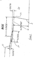
- the corresponding sealing surface 24 on the box section 20 can be defined in similar fashion to that described for the pin 10 and is shown in Figure 2 .
- the box section 20 has a recess, complementary in shape to the end of the pin section 10, which recess is defined by the surfaces as follows: a torque surface 21 is of the same or similar orientation relative to the main axis of the box section 20 as the torque surface 11 and engages frictionally or sealingly with the torque surface 11 on make-up of the joint between the pin and box sections.
- the torque surface 21 is joined by curved surface 23 to the planar surface 22.
- the sealing surface 24 then extends smoothly from the planar surface 22 and is operably connected to the first crest 25 of the thread on the box section 20.
- the sealing surface 24 again follows a portion of an ellipse which is defined as follows. Firstly, the surfaces 21 and 22 are extended to define a point which actually lies within the body of the box section 20. This point is shown with an X in Figure 2 . The centre of the ellipse is then set to be at a distance, as measured in the direction of the line parallel to the main longitudinal axis away from the main body of the box section 20 of 0.2652" (0.6736cm). It has been found that a suitable range of values for the distance is from 0.2550-0.2800" (0.6477-0.7112cm).
- the centre of the ellipse is on the line parallel to the main axis of the pipe but displaced by 0.0178" (0.0452cm) radially outwards from that axis.
- the displacement can be from 0.0165-0.0200" (0.0149-0.0508cm).
- the length of the long axis of the ellipse is 0.1503" (0.3818cm), although a length of from 0.1420-0.1650" (0.3607-0.4191cm) has been found to be suitable.
- the length of the short axis is 0.0192" (0.0488cm), although a length of from 0.0180-0.0205" (0.4572-0.5207cm) has been found to be suitable.
- the long axis of the ellipse is set at an angle to that of the main longitudinal axis of the pipe.
- the long axis of the ellipse is at an angle of 6.195°, although a range of from 5.0-8.0° has been found to be suitable and a range of 5.5-7.0° particularly suitable.
- the present invention utilises two elliptically curved surfaces in which the curvature, the dimensions and the orientation of the ellipses is selected to provide an effective seal which is capable of retaining its integrity as the two pipes move or are subjected to unequal internal and external pressures.
Landscapes
- Engineering & Computer Science (AREA)
- General Engineering & Computer Science (AREA)
- Mechanical Engineering (AREA)
- Non-Disconnectible Joints And Screw-Threaded Joints (AREA)
- Earth Drilling (AREA)
- Gasket Seals (AREA)
Applications Claiming Priority (2)
| Application Number | Priority Date | Filing Date | Title |
|---|---|---|---|
| GBGB1019413.2A GB201019413D0 (en) | 2010-11-17 | 2010-11-17 | An improved seal between pipes |
| PCT/GB2010/002260 WO2012066266A1 (en) | 2010-11-17 | 2010-12-13 | An improved seal between pipes |
Publications (2)
| Publication Number | Publication Date |
|---|---|
| EP2641007A1 EP2641007A1 (en) | 2013-09-25 |
| EP2641007B1 true EP2641007B1 (en) | 2016-03-02 |
Family
ID=43431541
Family Applications (1)
| Application Number | Title | Priority Date | Filing Date |
|---|---|---|---|
| EP10801672.6A Active EP2641007B1 (en) | 2010-11-17 | 2010-12-13 | An improved seal between pipes |
Country Status (16)
| Country | Link |
|---|---|
| US (1) | US8973953B2 (pl) |
| EP (1) | EP2641007B1 (pl) |
| JP (1) | JP5706533B2 (pl) |
| CN (1) | CN103238017B (pl) |
| AR (1) | AR083913A1 (pl) |
| BR (1) | BR112013011960B1 (pl) |
| CA (1) | CA2727754C (pl) |
| DK (1) | DK2641007T3 (pl) |
| EA (1) | EA027101B1 (pl) |
| ES (1) | ES2573709T3 (pl) |
| GB (2) | GB201019413D0 (pl) |
| HU (1) | HUE028563T2 (pl) |
| MX (1) | MX2013005566A (pl) |
| MY (1) | MY155767A (pl) |
| PL (1) | PL2641007T3 (pl) |
| WO (1) | WO2012066266A1 (pl) |
Families Citing this family (8)
| Publication number | Priority date | Publication date | Assignee | Title |
|---|---|---|---|---|
| MX367486B (es) * | 2013-01-28 | 2019-08-23 | Jfe Steel Corp | Junta roscada para tuberias de acero. |
| CN104074472B (zh) * | 2014-07-22 | 2015-05-13 | 江苏和信石油机械有限公司 | 超抗扭多台肩的全密封锥管螺纹连接装置 |
| CN104074473B (zh) * | 2014-07-22 | 2015-05-13 | 江苏和信石油机械有限公司 | 用于超深油气井钻探的钻杆连接装置 |
| RU2604461C1 (ru) * | 2015-08-21 | 2016-12-10 | Открытое акционерное общество "Первоуральский новотрубный завод" | Резьбовое трубное соединение |
| US9683684B1 (en) | 2015-12-09 | 2017-06-20 | Certus Energy Solutions, Llc | Tubular coupling |
| US11466800B2 (en) | 2015-12-09 | 2022-10-11 | Certus Energy Solutions, Llc | Tubular coupling |
| UA122027C2 (uk) * | 2016-08-24 | 2020-08-25 | ДжФЕ СТІЛ КОРПОРЕЙШН | Різьбове з'єднання для трубних виробів нафтопромислового сортаменту |
| MX2019012982A (es) * | 2017-05-22 | 2019-12-18 | Nippon Steel Corp | Conexion roscada para tubos de acero. |
Family Cites Families (23)
| Publication number | Priority date | Publication date | Assignee | Title |
|---|---|---|---|---|
| NL155335C (pl) * | 1971-07-09 | 1900-01-01 | ||
| IT1044052B (it) * | 1974-09-27 | 1980-03-20 | Mannesmann Roehren Werke Ag | Giunto filettato per tubi petroliferi |
| EP0087557B1 (de) * | 1982-02-27 | 1985-05-15 | MANNESMANN Aktiengesellschaft | Rohrverbindung für Metallrohre |
| JPS6060392A (ja) * | 1983-09-13 | 1985-04-06 | 住友金属工業株式会社 | 油井管用管継手 |
| US4624488A (en) * | 1983-12-16 | 1986-11-25 | Hydril Company | Tubular connection |
| GB8414203D0 (en) * | 1984-06-04 | 1984-07-11 | Hunting Oilfield Services Ltd | Pipe connectors |
| ATE36395T1 (de) * | 1986-01-23 | 1988-08-15 | Mannesmann Ag | Rohrverbindung fuer oel- und gasfeldrohre. |
| GB8617827D0 (en) * | 1986-07-22 | 1986-08-28 | British Steel Corp | Joints for tubular members |
| DE8707965U1 (de) * | 1987-06-04 | 1987-07-30 | Dalmine S.P.A., Mailand/Milano | Muffenlose Rohrkupplung für Kohlenwasserstoff-Pumprohrleitungen |
| US4944538A (en) * | 1989-03-08 | 1990-07-31 | Baroid Technology, Inc. | Threaded pipe joint having improved seal ring entrapment |
| US5137310A (en) * | 1990-11-27 | 1992-08-11 | Vallourec Industries | Assembly arrangement using frustoconical screwthreads for tubes |
| JP2877010B2 (ja) | 1994-11-04 | 1999-03-31 | 住友金属工業株式会社 | 油井管用ネジ継手 |
| JP3287197B2 (ja) | 1995-11-30 | 2002-05-27 | 住友金属工業株式会社 | 油井管用ねじ継手 |
| JPH10148281A (ja) | 1996-11-20 | 1998-06-02 | Kawasaki Steel Corp | 鋼管ネジ継手 |
| EP0916883B1 (en) * | 1997-05-30 | 2006-06-28 | Sumitomo Metal Industries, Ltd. | Screw joint for oil well pipe |
| DE19955377C2 (de) | 1999-11-10 | 2002-05-02 | Mannesmann Ag | Rohrverbindung |
| FR2833335B1 (fr) | 2001-12-07 | 2007-05-18 | Vallourec Mannesmann Oil & Gas | Joint filete tubulaire superieur contenant au moins un element filete avec levre d'extremite |
| US6832789B2 (en) | 2002-11-01 | 2004-12-21 | Torquelock Corporation | Threaded pipe connection with cylindrical metal-to-metal, high pressure containment seal |
| GB0227603D0 (en) | 2002-11-27 | 2002-12-31 | Hsc S A L | Improved casino joints |
| UA82694C2 (uk) * | 2003-06-06 | 2008-05-12 | Sumitomo Metal Ind | Нарізне з'єднання для сталевих труб |
| RU2387912C2 (ru) * | 2004-12-06 | 2010-04-27 | ЭйчДжиДиЭс ИНК. | Трубное соединение |
| WO2010047406A1 (en) * | 2008-10-20 | 2010-04-29 | Sumitomo Metal Industries, Ltd. | Threaded joint for steel pipes |
| GB201005247D0 (en) | 2010-03-29 | 2010-05-12 | Hsc Fzco | An improved seal between pipes |
-
2010
- 2010-11-17 GB GBGB1019413.2A patent/GB201019413D0/en not_active Ceased
- 2010-12-13 EA EA201390721A patent/EA027101B1/ru unknown
- 2010-12-13 ES ES10801672.6T patent/ES2573709T3/es active Active
- 2010-12-13 MY MYPI2013001575A patent/MY155767A/en unknown
- 2010-12-13 US US13/054,937 patent/US8973953B2/en active Active
- 2010-12-13 MX MX2013005566A patent/MX2013005566A/es active IP Right Grant
- 2010-12-13 BR BR112013011960-8A patent/BR112013011960B1/pt active IP Right Grant
- 2010-12-13 WO PCT/GB2010/002260 patent/WO2012066266A1/en not_active Ceased
- 2010-12-13 JP JP2013539327A patent/JP5706533B2/ja active Active
- 2010-12-13 HU HUE10801672A patent/HUE028563T2/en unknown
- 2010-12-13 DK DK10801672.6T patent/DK2641007T3/en active
- 2010-12-13 PL PL10801672.6T patent/PL2641007T3/pl unknown
- 2010-12-13 EP EP10801672.6A patent/EP2641007B1/en active Active
- 2010-12-13 CN CN201080070185.3A patent/CN103238017B/zh active Active
- 2010-12-13 CA CA2727754A patent/CA2727754C/en active Active
-
2011
- 2011-11-15 GB GB1119673.0A patent/GB2485661B/en active Active
- 2011-11-17 AR ARP110104298A patent/AR083913A1/es active IP Right Grant
Also Published As
| Publication number | Publication date |
|---|---|
| GB201119673D0 (en) | 2011-12-28 |
| US20120119488A1 (en) | 2012-05-17 |
| BR112013011960B1 (pt) | 2020-03-17 |
| US8973953B2 (en) | 2015-03-10 |
| ES2573709T3 (es) | 2016-06-09 |
| GB2485661A (en) | 2012-05-23 |
| WO2012066266A1 (en) | 2012-05-24 |
| GB2485661B (en) | 2012-10-03 |
| JP5706533B2 (ja) | 2015-04-22 |
| BR112013011960A2 (pt) | 2016-08-30 |
| EP2641007A1 (en) | 2013-09-25 |
| EA201390721A1 (ru) | 2013-09-30 |
| AR083913A1 (es) | 2013-04-10 |
| HK1168889A1 (en) | 2013-01-11 |
| EA027101B1 (ru) | 2017-06-30 |
| CA2727754A1 (en) | 2012-05-17 |
| CN103238017B (zh) | 2015-11-25 |
| CA2727754C (en) | 2014-06-17 |
| CN103238017A (zh) | 2013-08-07 |
| MX2013005566A (es) | 2013-08-26 |
| MY155767A (en) | 2015-11-30 |
| DK2641007T3 (en) | 2016-06-06 |
| GB201019413D0 (en) | 2010-12-29 |
| JP2014500450A (ja) | 2014-01-09 |
| HUE028563T2 (en) | 2016-12-28 |
| PL2641007T3 (pl) | 2016-09-30 |
Similar Documents
| Publication | Publication Date | Title |
|---|---|---|
| EP2572132B1 (en) | An improved seal between pipes | |
| EP2641007B1 (en) | An improved seal between pipes | |
| US4537429A (en) | Tubular connection with cylindrical and tapered stepped threads | |
| JP7654631B2 (ja) | 炭化水素井の掘削および/または開発のための管状ねじ接続部 | |
| MX2008012234A (es) | Junta roscada tubular. | |
| RU2637783C1 (ru) | Резьбовое соединение для толстостенных трубных изделий нефтепромыслового сортамента | |
| WO2004109173A1 (en) | Threaded joint for steel pipes | |
| US20150191980A1 (en) | Sealed threaded joint for tubing pipes | |
| EP3230551A1 (en) | Tubular component with a helical abutment | |
| WO1984004352A1 (en) | Tubular connection with cylindrical and tapered stepped threads | |
| EP1371892A1 (en) | Method of manufacturing threaded joint for oil well pipe | |
| CA2727745C (en) | An improved seal between pipes | |
| EP3405644B1 (en) | Pipe coupling | |
| EP1252462B1 (en) | Screw-threaded pipe joint | |
| WO2023021420A1 (en) | Improvements to a joint between oil and gas pipe sections | |
| WO2006061577A1 (en) | Improved pipe connection | |
| MX2011010472A (es) | Conexion roscada conica de hilo incremental trapezoidal. |
Legal Events
| Date | Code | Title | Description |
|---|---|---|---|
| PUAI | Public reference made under article 153(3) epc to a published international application that has entered the european phase |
Free format text: ORIGINAL CODE: 0009012 |
|
| 17P | Request for examination filed |
Effective date: 20130426 |
|
| AK | Designated contracting states |
Kind code of ref document: A1 Designated state(s): AL AT BE BG CH CY CZ DE DK EE ES FI FR GB GR HR HU IE IS IT LI LT LU LV MC MK MT NL NO PL PT RO RS SE SI SK SM TR |
|
| DAX | Request for extension of the european patent (deleted) | ||
| 17Q | First examination report despatched |
Effective date: 20150623 |
|
| GRAP | Despatch of communication of intention to grant a patent |
Free format text: ORIGINAL CODE: EPIDOSNIGR1 |
|
| INTG | Intention to grant announced |
Effective date: 20150902 |
|
| GRAS | Grant fee paid |
Free format text: ORIGINAL CODE: EPIDOSNIGR3 |
|
| GRAA | (expected) grant |
Free format text: ORIGINAL CODE: 0009210 |
|
| AK | Designated contracting states |
Kind code of ref document: B1 Designated state(s): AL AT BE BG CH CY CZ DE DK EE ES FI FR GB GR HR HU IE IS IT LI LT LU LV MC MK MT NL NO PL PT RO RS SE SI SK SM TR |
|
| REG | Reference to a national code |
Ref country code: GB Ref legal event code: FG4D |
|
| REG | Reference to a national code |
Ref country code: AT Ref legal event code: REF Ref document number: 778298 Country of ref document: AT Kind code of ref document: T Effective date: 20160315 Ref country code: CH Ref legal event code: EP |
|
| REG | Reference to a national code |
Ref country code: IE Ref legal event code: FG4D |
|
| REG | Reference to a national code |
Ref country code: DE Ref legal event code: R096 Ref document number: 602010030958 Country of ref document: DE |
|
| REG | Reference to a national code |
Ref country code: RO Ref legal event code: EPE |
|
| REG | Reference to a national code |
Ref country code: NL Ref legal event code: FP |
|
| REG | Reference to a national code |
Ref country code: DK Ref legal event code: T3 Effective date: 20160602 |
|
| REG | Reference to a national code |
Ref country code: ES Ref legal event code: FG2A Ref document number: 2573709 Country of ref document: ES Kind code of ref document: T3 Effective date: 20160609 |
|
| REG | Reference to a national code |
Ref country code: LT Ref legal event code: MG4D |
|
| REG | Reference to a national code |
Ref country code: NO Ref legal event code: T2 Effective date: 20160302 |
|
| PG25 | Lapsed in a contracting state [announced via postgrant information from national office to epo] |
Ref country code: FI Free format text: LAPSE BECAUSE OF FAILURE TO SUBMIT A TRANSLATION OF THE DESCRIPTION OR TO PAY THE FEE WITHIN THE PRESCRIBED TIME-LIMIT Effective date: 20160302 Ref country code: HR Free format text: LAPSE BECAUSE OF FAILURE TO SUBMIT A TRANSLATION OF THE DESCRIPTION OR TO PAY THE FEE WITHIN THE PRESCRIBED TIME-LIMIT Effective date: 20160302 |
|
| PG25 | Lapsed in a contracting state [announced via postgrant information from national office to epo] |
Ref country code: LT Free format text: LAPSE BECAUSE OF FAILURE TO SUBMIT A TRANSLATION OF THE DESCRIPTION OR TO PAY THE FEE WITHIN THE PRESCRIBED TIME-LIMIT Effective date: 20160302 Ref country code: LV Free format text: LAPSE BECAUSE OF FAILURE TO SUBMIT A TRANSLATION OF THE DESCRIPTION OR TO PAY THE FEE WITHIN THE PRESCRIBED TIME-LIMIT Effective date: 20160302 Ref country code: SE Free format text: LAPSE BECAUSE OF FAILURE TO SUBMIT A TRANSLATION OF THE DESCRIPTION OR TO PAY THE FEE WITHIN THE PRESCRIBED TIME-LIMIT Effective date: 20160302 Ref country code: RS Free format text: LAPSE BECAUSE OF FAILURE TO SUBMIT A TRANSLATION OF THE DESCRIPTION OR TO PAY THE FEE WITHIN THE PRESCRIBED TIME-LIMIT Effective date: 20160302 |
|
| REG | Reference to a national code |
Ref country code: SK Ref legal event code: T3 Ref document number: E 21170 Country of ref document: SK Ref country code: GR Ref legal event code: EP Ref document number: 20160401024 Country of ref document: GR Effective date: 20160628 |
|
| PG25 | Lapsed in a contracting state [announced via postgrant information from national office to epo] |
Ref country code: EE Free format text: LAPSE BECAUSE OF FAILURE TO SUBMIT A TRANSLATION OF THE DESCRIPTION OR TO PAY THE FEE WITHIN THE PRESCRIBED TIME-LIMIT Effective date: 20160302 |
|
| PG25 | Lapsed in a contracting state [announced via postgrant information from national office to epo] |
Ref country code: PT Free format text: LAPSE BECAUSE OF FAILURE TO SUBMIT A TRANSLATION OF THE DESCRIPTION OR TO PAY THE FEE WITHIN THE PRESCRIBED TIME-LIMIT Effective date: 20160704 Ref country code: SM Free format text: LAPSE BECAUSE OF FAILURE TO SUBMIT A TRANSLATION OF THE DESCRIPTION OR TO PAY THE FEE WITHIN THE PRESCRIBED TIME-LIMIT Effective date: 20160302 |
|
| REG | Reference to a national code |
Ref country code: DE Ref legal event code: R097 Ref document number: 602010030958 Country of ref document: DE |
|
| REG | Reference to a national code |
Ref country code: FR Ref legal event code: PLFP Year of fee payment: 7 |
|
| REG | Reference to a national code |
Ref country code: HU Ref legal event code: AG4A Ref document number: E028563 Country of ref document: HU |
|
| PG25 | Lapsed in a contracting state [announced via postgrant information from national office to epo] |
Ref country code: BE Free format text: LAPSE BECAUSE OF FAILURE TO SUBMIT A TRANSLATION OF THE DESCRIPTION OR TO PAY THE FEE WITHIN THE PRESCRIBED TIME-LIMIT Effective date: 20160302 |
|
| PLBE | No opposition filed within time limit |
Free format text: ORIGINAL CODE: 0009261 |
|
| STAA | Information on the status of an ep patent application or granted ep patent |
Free format text: STATUS: NO OPPOSITION FILED WITHIN TIME LIMIT |
|
| 26N | No opposition filed |
Effective date: 20161205 |
|
| PG25 | Lapsed in a contracting state [announced via postgrant information from national office to epo] |
Ref country code: SI Free format text: LAPSE BECAUSE OF FAILURE TO SUBMIT A TRANSLATION OF THE DESCRIPTION OR TO PAY THE FEE WITHIN THE PRESCRIBED TIME-LIMIT Effective date: 20160302 Ref country code: BG Free format text: LAPSE BECAUSE OF FAILURE TO SUBMIT A TRANSLATION OF THE DESCRIPTION OR TO PAY THE FEE WITHIN THE PRESCRIBED TIME-LIMIT Effective date: 20160602 |
|
| REG | Reference to a national code |
Ref country code: CH Ref legal event code: PL |
|
| PG25 | Lapsed in a contracting state [announced via postgrant information from national office to epo] |
Ref country code: MC Free format text: LAPSE BECAUSE OF FAILURE TO SUBMIT A TRANSLATION OF THE DESCRIPTION OR TO PAY THE FEE WITHIN THE PRESCRIBED TIME-LIMIT Effective date: 20160302 |
|
| PG25 | Lapsed in a contracting state [announced via postgrant information from national office to epo] |
Ref country code: CH Free format text: LAPSE BECAUSE OF NON-PAYMENT OF DUE FEES Effective date: 20161231 Ref country code: LI Free format text: LAPSE BECAUSE OF NON-PAYMENT OF DUE FEES Effective date: 20161231 |
|
| REG | Reference to a national code |
Ref country code: FR Ref legal event code: PLFP Year of fee payment: 8 |
|
| REG | Reference to a national code |
Ref country code: AT Ref legal event code: UEP Ref document number: 778298 Country of ref document: AT Kind code of ref document: T Effective date: 20160302 |
|
| PG25 | Lapsed in a contracting state [announced via postgrant information from national office to epo] |
Ref country code: CY Free format text: LAPSE BECAUSE OF FAILURE TO SUBMIT A TRANSLATION OF THE DESCRIPTION OR TO PAY THE FEE WITHIN THE PRESCRIBED TIME-LIMIT Effective date: 20160302 |
|
| PG25 | Lapsed in a contracting state [announced via postgrant information from national office to epo] |
Ref country code: MK Free format text: LAPSE BECAUSE OF FAILURE TO SUBMIT A TRANSLATION OF THE DESCRIPTION OR TO PAY THE FEE WITHIN THE PRESCRIBED TIME-LIMIT Effective date: 20160302 |
|
| PG25 | Lapsed in a contracting state [announced via postgrant information from national office to epo] |
Ref country code: MT Free format text: LAPSE BECAUSE OF NON-PAYMENT OF DUE FEES Effective date: 20161213 |
|
| PG25 | Lapsed in a contracting state [announced via postgrant information from national office to epo] |
Ref country code: AL Free format text: LAPSE BECAUSE OF FAILURE TO SUBMIT A TRANSLATION OF THE DESCRIPTION OR TO PAY THE FEE WITHIN THE PRESCRIBED TIME-LIMIT Effective date: 20160302 |
|
| PGFP | Annual fee paid to national office [announced via postgrant information from national office to epo] |
Ref country code: ES Payment date: 20250121 Year of fee payment: 15 |
|
| PGFP | Annual fee paid to national office [announced via postgrant information from national office to epo] |
Ref country code: IS Payment date: 20251229 Year of fee payment: 16 Ref country code: DE Payment date: 20251103 Year of fee payment: 16 |
|
| PGFP | Annual fee paid to national office [announced via postgrant information from national office to epo] |
Ref country code: GB Payment date: 20251103 Year of fee payment: 16 |
|
| PGFP | Annual fee paid to national office [announced via postgrant information from national office to epo] |
Ref country code: NO Payment date: 20251218 Year of fee payment: 16 |
|
| PGFP | Annual fee paid to national office [announced via postgrant information from national office to epo] |
Ref country code: AT Payment date: 20251218 Year of fee payment: 16 |
|
| PGFP | Annual fee paid to national office [announced via postgrant information from national office to epo] |
Ref country code: DK Payment date: 20251222 Year of fee payment: 16 Ref country code: IT Payment date: 20251103 Year of fee payment: 16 |
|
| PGFP | Annual fee paid to national office [announced via postgrant information from national office to epo] |
Ref country code: LU Payment date: 20251222 Year of fee payment: 16 Ref country code: HU Payment date: 20251203 Year of fee payment: 16 Ref country code: NL Payment date: 20251219 Year of fee payment: 16 Ref country code: FR Payment date: 20251222 Year of fee payment: 16 |
|
| PGFP | Annual fee paid to national office [announced via postgrant information from national office to epo] |
Ref country code: TR Payment date: 20251126 Year of fee payment: 16 Ref country code: GR Payment date: 20251218 Year of fee payment: 16 |
|
| PGFP | Annual fee paid to national office [announced via postgrant information from national office to epo] |
Ref country code: CZ Payment date: 20251128 Year of fee payment: 16 Ref country code: IE Payment date: 20251103 Year of fee payment: 16 |
|
| PGFP | Annual fee paid to national office [announced via postgrant information from national office to epo] |
Ref country code: PL Payment date: 20251121 Year of fee payment: 16 |
|
| PGFP | Annual fee paid to national office [announced via postgrant information from national office to epo] |
Ref country code: RO Payment date: 20251203 Year of fee payment: 16 Ref country code: SK Payment date: 20251124 Year of fee payment: 16 |