EP2640631B1 - Water intake riser assembly for an off-shore structure, and methods of producing a liquefied and a vaporous hydrocarbon stream - Google Patents
Water intake riser assembly for an off-shore structure, and methods of producing a liquefied and a vaporous hydrocarbon stream Download PDFInfo
- Publication number
- EP2640631B1 EP2640631B1 EP20110787822 EP11787822A EP2640631B1 EP 2640631 B1 EP2640631 B1 EP 2640631B1 EP 20110787822 EP20110787822 EP 20110787822 EP 11787822 A EP11787822 A EP 11787822A EP 2640631 B1 EP2640631 B1 EP 2640631B1
- Authority
- EP
- European Patent Office
- Prior art keywords
- water
- water intake
- riser assembly
- tubular
- tubular conduit
- Prior art date
- Legal status (The legal status is an assumption and is not a legal conclusion. Google has not performed a legal analysis and makes no representation as to the accuracy of the status listed.)
- Active
Links
- XLYOFNOQVPJJNP-UHFFFAOYSA-N water Substances O XLYOFNOQVPJJNP-UHFFFAOYSA-N 0.000 title claims description 125
- 229930195733 hydrocarbon Natural products 0.000 title claims description 48
- 150000002430 hydrocarbons Chemical class 0.000 title claims description 48
- 239000004215 Carbon black (E152) Substances 0.000 title claims description 47
- 238000000034 method Methods 0.000 title claims description 13
- 125000006850 spacer group Chemical group 0.000 claims description 23
- 239000000725 suspension Substances 0.000 claims description 3
- VNWKTOKETHGBQD-UHFFFAOYSA-N methane Chemical compound C VNWKTOKETHGBQD-UHFFFAOYSA-N 0.000 description 8
- 239000003949 liquefied natural gas Substances 0.000 description 7
- 239000000463 material Substances 0.000 description 4
- 239000003345 natural gas Substances 0.000 description 4
- 239000000498 cooling water Substances 0.000 description 2
- 238000007689 inspection Methods 0.000 description 2
- 238000009434 installation Methods 0.000 description 2
- 229910000975 Carbon steel Inorganic materials 0.000 description 1
- 229910000831 Steel Inorganic materials 0.000 description 1
- 238000003491 array Methods 0.000 description 1
- 230000000712 assembly Effects 0.000 description 1
- 238000000429 assembly Methods 0.000 description 1
- 239000010962 carbon steel Substances 0.000 description 1
- 238000004140 cleaning Methods 0.000 description 1
- 230000002301 combined effect Effects 0.000 description 1
- 230000002153 concerted effect Effects 0.000 description 1
- 238000010276 construction Methods 0.000 description 1
- 239000000356 contaminant Substances 0.000 description 1
- 230000008878 coupling Effects 0.000 description 1
- 238000010168 coupling process Methods 0.000 description 1
- 238000005859 coupling reaction Methods 0.000 description 1
- 239000007787 solid Substances 0.000 description 1
- 239000010959 steel Substances 0.000 description 1
- 230000001629 suppression Effects 0.000 description 1
- 238000009834 vaporization Methods 0.000 description 1
Images

Classifications
-
- E—FIXED CONSTRUCTIONS
- E21—EARTH OR ROCK DRILLING; MINING
- E21B—EARTH OR ROCK DRILLING; OBTAINING OIL, GAS, WATER, SOLUBLE OR MELTABLE MATERIALS OR A SLURRY OF MINERALS FROM WELLS
- E21B17/00—Drilling rods or pipes; Flexible drill strings; Kellies; Drill collars; Sucker rods; Cables; Casings; Tubings
- E21B17/01—Risers
-
- B—PERFORMING OPERATIONS; TRANSPORTING
- B63—SHIPS OR OTHER WATERBORNE VESSELS; RELATED EQUIPMENT
- B63B—SHIPS OR OTHER WATERBORNE VESSELS; EQUIPMENT FOR SHIPPING
- B63B35/00—Vessels or similar floating structures specially adapted for specific purposes and not otherwise provided for
-
- B—PERFORMING OPERATIONS; TRANSPORTING
- B63—SHIPS OR OTHER WATERBORNE VESSELS; RELATED EQUIPMENT
- B63J—AUXILIARIES ON VESSELS
- B63J2/00—Arrangements of ventilation, heating, cooling, or air-conditioning
- B63J2/12—Heating; Cooling
-
- F—MECHANICAL ENGINEERING; LIGHTING; HEATING; WEAPONS; BLASTING
- F25—REFRIGERATION OR COOLING; COMBINED HEATING AND REFRIGERATION SYSTEMS; HEAT PUMP SYSTEMS; MANUFACTURE OR STORAGE OF ICE; LIQUEFACTION SOLIDIFICATION OF GASES
- F25J—LIQUEFACTION, SOLIDIFICATION OR SEPARATION OF GASES OR GASEOUS OR LIQUEFIED GASEOUS MIXTURES BY PRESSURE AND COLD TREATMENT OR BY BRINGING THEM INTO THE SUPERCRITICAL STATE
- F25J1/00—Processes or apparatus for liquefying or solidifying gases or gaseous mixtures
- F25J1/0002—Processes or apparatus for liquefying or solidifying gases or gaseous mixtures characterised by the fluid to be liquefied
- F25J1/0022—Hydrocarbons, e.g. natural gas
-
- F—MECHANICAL ENGINEERING; LIGHTING; HEATING; WEAPONS; BLASTING
- F25—REFRIGERATION OR COOLING; COMBINED HEATING AND REFRIGERATION SYSTEMS; HEAT PUMP SYSTEMS; MANUFACTURE OR STORAGE OF ICE; LIQUEFACTION SOLIDIFICATION OF GASES
- F25J—LIQUEFACTION, SOLIDIFICATION OR SEPARATION OF GASES OR GASEOUS OR LIQUEFIED GASEOUS MIXTURES BY PRESSURE AND COLD TREATMENT OR BY BRINGING THEM INTO THE SUPERCRITICAL STATE
- F25J1/00—Processes or apparatus for liquefying or solidifying gases or gaseous mixtures
- F25J1/02—Processes or apparatus for liquefying or solidifying gases or gaseous mixtures requiring the use of refrigeration, e.g. of helium or hydrogen ; Details and kind of the refrigeration system used; Integration with other units or processes; Controlling aspects of the process
- F25J1/0243—Start-up or control of the process; Details of the apparatus used; Details of the refrigerant compression system used
- F25J1/0257—Construction and layout of liquefaction equipments, e.g. valves, machines
- F25J1/0275—Construction and layout of liquefaction equipments, e.g. valves, machines adapted for special use of the liquefaction unit, e.g. portable or transportable devices
- F25J1/0277—Offshore use, e.g. during shipping
- F25J1/0278—Unit being stationary, e.g. on floating barge or fixed platform
-
- F—MECHANICAL ENGINEERING; LIGHTING; HEATING; WEAPONS; BLASTING
- F25—REFRIGERATION OR COOLING; COMBINED HEATING AND REFRIGERATION SYSTEMS; HEAT PUMP SYSTEMS; MANUFACTURE OR STORAGE OF ICE; LIQUEFACTION SOLIDIFICATION OF GASES
- F25J—LIQUEFACTION, SOLIDIFICATION OR SEPARATION OF GASES OR GASEOUS OR LIQUEFIED GASEOUS MIXTURES BY PRESSURE AND COLD TREATMENT OR BY BRINGING THEM INTO THE SUPERCRITICAL STATE
- F25J1/00—Processes or apparatus for liquefying or solidifying gases or gaseous mixtures
- F25J1/02—Processes or apparatus for liquefying or solidifying gases or gaseous mixtures requiring the use of refrigeration, e.g. of helium or hydrogen ; Details and kind of the refrigeration system used; Integration with other units or processes; Controlling aspects of the process
- F25J1/0243—Start-up or control of the process; Details of the apparatus used; Details of the refrigerant compression system used
- F25J1/0279—Compression of refrigerant or internal recycle fluid, e.g. kind of compressor, accumulator, suction drum etc.
- F25J1/0296—Removal of the heat of compression, e.g. within an inter- or afterstage-cooler against an ambient heat sink
- F25J1/0297—Removal of the heat of compression, e.g. within an inter- or afterstage-cooler against an ambient heat sink using an externally chilled fluid, e.g. chilled water
-
- B—PERFORMING OPERATIONS; TRANSPORTING
- B63—SHIPS OR OTHER WATERBORNE VESSELS; RELATED EQUIPMENT
- B63B—SHIPS OR OTHER WATERBORNE VESSELS; EQUIPMENT FOR SHIPPING
- B63B13/00—Conduits for emptying or ballasting; Self-bailing equipment; Scuppers
-
- B—PERFORMING OPERATIONS; TRANSPORTING
- B63—SHIPS OR OTHER WATERBORNE VESSELS; RELATED EQUIPMENT
- B63B—SHIPS OR OTHER WATERBORNE VESSELS; EQUIPMENT FOR SHIPPING
- B63B35/00—Vessels or similar floating structures specially adapted for specific purposes and not otherwise provided for
- B63B35/44—Floating buildings, stores, drilling platforms, or workshops, e.g. carrying water-oil separating devices
- B63B2035/4473—Floating structures supporting industrial plants, such as factories, refineries, or the like
-
- B—PERFORMING OPERATIONS; TRANSPORTING
- B63—SHIPS OR OTHER WATERBORNE VESSELS; RELATED EQUIPMENT
- B63J—AUXILIARIES ON VESSELS
- B63J2/00—Arrangements of ventilation, heating, cooling, or air-conditioning
- B63J2002/005—Intakes for coolant medium other than sea chests, e.g. for ambient water
Definitions
- the present invention relates to a water intake riser assembly that is suspendable from an off-shore structure and/or an off-shore structure from which such a water intake riser assembly is suspended.
- the invention relates to a method of producing a liquefied hydrocarbon stream employing such a water intake riser assembly and/or a of producing a vaporous hydrocarbon stream employing such a water intake riser assembly.
- WO 2004/085238 discloses a water intake riser used on a vessel on which a plant for liquefying natural gas is arranged, to provide cooling water to a heat exchanger.
- WO 2010/085302 discloses a marine system including a Floating Liquefied Natural Gas (FLNG) plant on/in a surface of the ocean.
- FLNG Floating Liquefied Natural Gas
- the FLNG plant may cool and liquefy natural gas to form LNG, or alternatively heat and gasify LNG.
- a water riser assembly is suspended from the FLNG plant to take in cold water at depth and convey the cold water upward to the FLNG plant.
- the water riser assembly comprises tubular structures projecting downwardly into the ocean and connected together with a plurality of spacers.
- the spacers have openings through which respective ones of the tubular structures are disposed.
- One or more tubular structures of an array or grouping connected with FLNG plant may be used to bring water from the ocean to the plant.
- tubular structures are arranged in a three-by-three rectangular array and filters are provided on each of the bottoms of the tubular structures. If one of the filters clogs over time, the remaining tubuler structures may still convey sufficient water to the FLNG plant.
- the present invention provides a water intake riser assembly that is suspendable from an off-shore structure, comprising a bundle of at least a first tubular conduit and a second tubular conduit generally stretching side by side along a length direction, each comprising, seen in the length direction, a proximal portion comprising suspension means, followed by a connecting portion, followed by a distal portion comprising a water-intake section, said distal portion extending between a first distal end and the connecting portion of the respective tubular conduit, said connecting portion fluidly connecting the proximal portion and the distal portion, the first and second tubular conduits being laterally connected to each other by means of at least one spacer cooperating with the respective connecting portions, wherein at least a part of the distal portion of the first tubular conduit extends further in the length direction than the second tubular conduit when in fully suspended condition.
- Such a water intake riser assembly may be suspended from an off-shore structure to form an off-shore structure from which such a water intake riser assembly is suspended.
- the present invention provides a method of producing a liquefied hydrocarbon stream employing such a water intake riser assembly and a method of producing a vaporous hydrocarbon stream employing such a water intake riser assembly.
- the method producing a liquefied hydrocarbon stream comprises:
- the method of producing the vaporous hydrocarbon stream comprises:
- the present disclosure describes a water intake riser assembly that is suspendable from an off-shore structure, comprising a bundle of at least a first tubular conduit and a second tubular conduit generally stretching side by side along a length direction, of which at least a part of the distal portion of the first tubular conduit extends further in the length direction than the second tubular conduit when in fully suspended condition.
- the tubular conduits in the water intake riser assembly may serve to convey water taken in at the distal portion to the promimal portion.
- the tubular conduits in the water intake riser assembly may serve to convey water taken in at the distal portion to the promimal portion.
- the water intake riser assembly may be based on a bundle of more than two tubular conduits, for instance 8 or 9 tubular conduits arranged in a rectangular cross sectional pattern at least having one tubular conduit at each of the four corners and one tubular conduit between sets of two of the corners.
- the tubular conduits may be arranged in a concentric and/or circular pattern.
- FIG. 1 illustrates an example of a marine system 100 in which embodiments of the present invention may be implemented.
- the marine system 100 in this example includes an off-shore structure 102 on/in a surface of the ocean 104, here represented in the form of a floating structure.
- the off-shore structure 102 may comprise a Floating Liquefied Natural Gas (FLNG) plant as one example.
- FLNG Floating Liquefied Natural Gas
- the FLNG plant may cool and liquefy natural gas, or alternatively heat and vaporize LNG.
- a water intake riser assembly 105 is suspended from the off-shore structure 102 in fully suspended condition.
- the water intake riser assembly 105 may be used to bring water from the ocean to the plant.
- the water intake riser assembly 105 comprises a bundle 106 of at least a first tubular conduit 106A and a second tubular conduit 106B. These tubular conduits may take in cold water 140 at depth, and convey the cold water upward to the off-shore structure 102.
- the cold water may be input to heat exchangers to add or remove heat to/from a process performed on the off-shore structure 102. Heated or cooled ocean water from the outlet of the heat exchangers may be discharged back into the ocean at the surface, or alternatively conveyed back to depth with a discharge system.
- the first and second tubular conduits 106A,106B generally stretch side by side along a length direction. Seen in the length direction, each of the tubular conduits have a proximal portion 107, followed by a connecting portion 108, followed by a distal portion 109.
- the distal portions of the tubular conduits together, when fully suspended, form the distal part of the water intake riser assembly.
- the distal part of the water intake riser assembly hangs free from the ocean floor 103.
- the distal part of the water intake riser assembly hangs at a depth D of between around 130 to 170 meters from the surface of the ocean 104, although the water intake riser assembly may be employed at other depths as well.
- the proximal portion 107 comprises suspension means by which the tubular conduit is suspended from the off shore structure 102. Due to the ocean current, the tubular structures 106 may deflect from vertical, up to around 40 degrees or so (not shown). To accommodate for such deflection, the tubular structures 106 may be suspended from the off-shore structure through a swivel joint, a ball joint, a riser hanger, or other pivotable or hingeable coupling. Particular reference is made to US Patent 7,318,387 which describes a particularly suitable riser hanger construction involving a flexible load transfer element and a hose to convey the water.
- the distal portion 109 comprising a water-intake section, an example of which will be illustrated herein below with reference to Figures 4 and 5 .
- the distal portion 109 extends between a first distal end and the connecting portion 108.
- the connecting portion fluidly connects the proximal portion 107 and the distal portion 109. It can be seen in Figure 1 that at least part of the distal portion 109 of the first tubular conduit 106A extends further in the length direction than the second tubular conduit 106B.
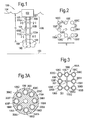
- FIG. 2 shows an example approach or configuration for nine tubular conduits (106A to 106I) arranged in a three-by-three rectangular array, according to one particular embodiment.
- This figure is a cross-sectional view taken along section plane 2 of Figure 1 , through the plurality of tubular conduits.
- the array has eight tubular structures along the periphery and one at the center.
- the tubular conduit 106E at the center may serve as a structural support structure for the spacers.
- the tubular conduit 106E at the center may, or may not, convey water to the surface (i.e., may or may not serve as a water intake riser).
- the eight tubular conduits along the periphery may have outer diameters sized d.
- the structural tubular conduit, in the example the central tubular conduit 106E, may have an outside diameter smaller than d.
- the eight tubular structures along the periphery may be equally spaced apart by a distance of about one outer diameter d.
- the tubular conduits (106A to 106I) are positioned on a square grid pattern with a grid spacing of about 2d.
- the first and second tubular conduits 106A,106B are laterally connected to each other by means of at least one spacer (110A; 110B, 110C) cooperating with the respective connecting portions 108 of the tubular conduits.
- spacers By means of such spacers, the tubular conduits are physically associated or connected together. In one embodiment, enough spacers may be provided to keep the tubular structures from striking into one another.
- FIG. 3 shows an example spacer 110A for nine tubular conduits (106A to 106I) arranged in the three-by-three rectangular array, according to one particular embodiment.
- This figure is a cross-sectional view taken along section plane 3 of Figure 1 , through the spacer 110A and the plurality of tubular conduits.
- the spacers may each comprise one or more a plurality of interconnected guide sleeves 306A to 306D and 306F to 306I, through which respective ones of the tubular conduits 106A to 106D and 106F to 106I are disposed.
- Bars 307 form the interconnection. At least one of the bars 307 is fixedly connected to the central tubular conduit 106E.
- the central tubular conduit 106E also passes through a guide sleeve in which case the spacer 110A should be supported by alternative means such as a rod, a wire, a chain connected to the offshore structure 102.
- Each guide sleeve 306 may define an aperture 301, which allows one of the elongated tubular conduits to pass freely through it and preferably allows limited rotation of the elongated tubular conduits about a horizontal axis.
- the horizontal axis is an axis that is lying in a plane of symmetry of the spacer 110A, which plane is perpendicular to the length direction of passage through the aperture 301.
- the spacer 110A is slidingly translatable relative to the first and second tubular conduits 106A, 106B along the length direction. This way, the first and second tubular conduits are retractable from the one spacer 110A for instance in case one needs to be replaced.
- Figure 3A shows an alternative embodiment, wherein for nine tubular structures arranged in a concentric array, according to one embodiment.
- the concentric array is circular.
- the array may be elliptical, oval, star shaped, triangular, etc..
- the bars 307 interconnecting the guide sleeves 306 of the spacer shown in Figure 3 have been replaced by a frame or by a solid body provided with holes representing the guide sleeves 306 or capable of holding the guide sleeves. This can be applied to rectangular arrays or other bundle patterns as well.
- Figure 4 shows a detailed view of an example of a lower end of one of the tubular conduits 106A, including its distal portion 109 and a part of the connecting portion 108.
- a guide cylinder 408 may be fitted around a section of the connecting portion 108 to engage with one of the spacers 110.
- Such a guide cylinder 408 may comprise of a different material than the connecting portion 108. Preferably it is less hard material than the material of the connecting portion 108 and/or the material of the inside of the guide sleeves to ensure that it wears faster than the connecting portion 108 and/or the guide sleeves.
- the connecting portion may comprise a plurality of pipes connected in a string by connectors 409.
- the inner diameter of the guide cylinder is suitably snugly fitting to the outer diameter of the tubular connecting portions.
- the wall thickness of the guide cylinder is suitably between 1.5 and 3 inches, depending on the outer diameter (larger diameter usually corresponding to larger wall thickness).
- the water intake section 403 in the distal portion 109 is provided with water intake openings 405 distributed along the water-intake section 403.
- the connecting portion 108 is free from water intake openings.
- the water-intake section 403 comprises a tubular section having a side wall 404 circumferencing around the length axis L.
- a flow passage is defined in the length direction L, with an aperture 402 having a first transverse cross sectional area A 1 .
- water intake openings 405 are provided as a plurality of through holes through the side wall 404. Each through hole defines a transverse access port into the flow passage and during operation allows a transversely directed flow of cold water 140 from the ocean into the flow passage.
- the aggregate inlet area defined by flow area through the plurality of through holes 405 is larger than the first transverse cross sectional area A 1 .
- the intake velocity of cold water 140 from the ocean just outside the water intake section 403 can remain below a maximum allowable velocity (in one example the maximum allowable intake velocity is 0.5 m/s) while the water flow velocity inside the tubular conduit can exceed the maximum allowable intake velocity.
- the aggregate inlet area is larger than 5 times A 1 .
- the aggregate inlet area is smaller than 50 times A 1 , preferably smaller than 10 times A 1 .
- the diameter at the distal portion may be kept relatively small.
- each of retracting the tubular conduits by sliding them along their length direction is facilitated.
- the through holes 405 are distributed over the majority of the circumference around the side wall 404.
- the concerted effect in the flow field caused by the plurality of water intake sections in the bundle is further reduced, because the through holes 405 can be accessed in a range of a radial directions.
- the volume of cold water flowing at the highest velocity is relatively low compared to taking in water in a direction along the length direction.
- the risk of full interruption of water conveyed to the proximal portion 107 due to clogging of the through holes is further reduced if the water intake openings 405 are distributed not only along the length of the water intake section 403 but also over the circumference.
- the tubular section of the water-intake section 403 is made of carbon steel with a steel grade of X70 or equivalent thereto. It may have an outer diameter of about 42 inches and wall thicknesses of about 1.5 inch.
- the through holes 405 may be drilled through the side wall 404.
- each through hole 405 is smaller than 10 cm in diameter to prevent large sea life from entering.
- each through hole 405 is larger than 1 cm in diameter to avoid clogging by build-up of relatively small particulates and to avoid big water pressure differentials.
- the diameter of the through holes 405 was selected to be about 5 cm.
- the distal portion 109 may comprise a shoe piece 410 at the distal end 401 to provide a rounded tip.
- the shoe piece 410 may be fitted to the side wall 404 of the distal portion 109. It may comprise a planar piece 411 protruding downwardly from the water intake section with the length direction in its plane.
- the shoe piece 410 may further comprise a baffle plate 412 extending perpendicularly to the length direction L to avoid intake of water at the lower tubular end of the water intake section 403.
- the baffle plate 412 may be provided with one or more smaller through holes 115 to facilitate limited water access to the flow passage 402. These through holes 115 may be of the same or similar size as the through holes 405 in the side wall 404.
- the planar piece 411 may have a downwardly protruding semi-circular or semi-oval outer contour.
- Second and third planar pieces 421 and 431 may be provided as well, as illustrated in Figure 5 which offers an upward view of the distal end 401 against the length direction.
- the planar piece 411 together with the second and third planar pieces 421 and 431 may form a crossed arrangement with the plane pieces protruding radially outwardly from a center axis CA defined by the intersection line where the planar pieces meet.
- More planare pieces may be provided if desired, preferably also radially extending from the centre axis.
- Figure 6 schematically shows a perspective view of the distal part of the water intake riser assembly 105 and showing staggeredly arranged distal portions 109.
- the example shows a bundle 106 of eight tubular conduits, including the first tubular conduit 106A and the second tubular conduit 106B. The shown portions of all eight tubular elements are of the same design each with the same components.
- a spacer 110 is fixedly connected to a central support rod 606.
- the central support rod 606 protrudes downwardly along the length direction and also fixedly supports an auxiliary contportions of an auxiliary spacer 610.
- the spacer 110 comprises eight guide sleeves 603, but fewer could be installed in other embodiments.
- the auxiliary space comprises four auxiliary guide sleeves 613 of the same design as the eight guide sleeves 603, interconnected by arms 607.
- each guide sleeve 603 comprises an upper portion 604 facing towards the proximal portion of the first and second tubular conduits 106A and 106B, and a lower portion 605 facing towards the distal portion 109 of the first tubular conduit 106A.
- the lower portion 605 is cylindrically shaped and embracing the first tubular element 106A.
- the tubular element 106A is optionally provided with a guide cylinder 408 as explained above.
- the upper portion 604 is funnel shaped, having a wider opening than the cylindrically shaped lower portion 605.
- the auxiliary guide sleeves 613 have similar upper portion 614 and lower portion 615. This design, preferably in combination with the shoe pieces at the distal ends providing a rounded tip, facilitates reinsertion of the tubular conduit after it has been retracted.
- the distal portion 109 of four of the eight tubular conduits, including the first tubular conduit 106A, extend further in the length direction L, than the four remaining tubular conduits including the second tubular conduit 106B.
- the first distal end 401 extends at least by an amount of L 1 further in the length direction than the second distal end 601.
- the distal portions 109 of the first tubular conduit 106A has at least a portion that is in lateral direction (in a plane perpendicular to the length direction) not overlappling with any part of the second tubular conduit 106B.
- the total length from the distal end 401 to the lowermost string connector 409 may be in the range of from 5 to 20 m. In one example, this length was about 14 m.
- the length of the water intake section 403 in one example was 8.5 m and the length of the optional guide cylinder 408 was about 3.4 m.
- tubular conduits in the present example are fully suspended for water intake operation, as opposed to being retracted from the guide sleeves for inspection, replacement or servicing.
- each of tubular conduit in the bundle may not be necessary to be in operation at any one time.
- one or more of the tubular conduits may serve as a surplus water intake riser.
- additional filters may optionally be coupled to each of the distal portions 109.
- more than one of the described water intake riser assemblies may be suspended from a single off shore structure.
- any number of or all of the tubular conduits may be provided with vortex induced vibration suppression means. Examples are described in for instance WO 2010/085302 .
- the water intake riser assembly as described above may be used to supply process water to any process carried out on the off-shore structure.
- it may be used in a method of producing a liquefied hydrocarbon stream, comprising:
- a well known example of a liquefied hydrocarbon stream is a liquefied natural gas stream.
- a variety of suitable installations and line ups are available in the art for extracting heat from a vaporous hydrocarbon containing feed stream, particularly a natural gas stream, as well as other treatment steps such as removal of unwanted contaminants and components from the feed stream often performed in conjunction with producing a liquefied hydrocarbon stream, and need not be further explained herein.
- the water intake riser assembly may be used in a method of producing a vaporous hydrocarbon stream, comprising:
Landscapes
- Engineering & Computer Science (AREA)
- Mechanical Engineering (AREA)
- Physics & Mathematics (AREA)
- Thermal Sciences (AREA)
- General Engineering & Computer Science (AREA)
- Chemical & Material Sciences (AREA)
- Ocean & Marine Engineering (AREA)
- Geology (AREA)
- Life Sciences & Earth Sciences (AREA)
- Mining & Mineral Resources (AREA)
- Combustion & Propulsion (AREA)
- Fluid Mechanics (AREA)
- Environmental & Geological Engineering (AREA)
- General Life Sciences & Earth Sciences (AREA)
- Geochemistry & Mineralogy (AREA)
- Oil, Petroleum & Natural Gas (AREA)
- General Chemical & Material Sciences (AREA)
- Chemical Kinetics & Catalysis (AREA)
- Filling Or Discharging Of Gas Storage Vessels (AREA)
- Organic Low-Molecular-Weight Compounds And Preparation Thereof (AREA)
- Production Of Liquid Hydrocarbon Mixture For Refining Petroleum (AREA)
- Separation By Low-Temperature Treatments (AREA)
- Earth Drilling (AREA)
- Vaporization, Distillation, Condensation, Sublimation, And Cold Traps (AREA)
Priority Applications (2)
| Application Number | Priority Date | Filing Date | Title |
|---|---|---|---|
| EP20110787822 EP2640631B1 (en) | 2010-11-18 | 2011-11-16 | Water intake riser assembly for an off-shore structure, and methods of producing a liquefied and a vaporous hydrocarbon stream |
| CY20151100120T CY1115977T1 (el) | 2010-11-18 | 2015-02-06 | Διαταξη κατακορυφου σωληνα ληψης νερου για μια παρακτια δομη και μεθοδοι παραγωγης υγροποιημενου και ατμωδους ρευματος υδρογονανθρακων |
Applications Claiming Priority (3)
| Application Number | Priority Date | Filing Date | Title |
|---|---|---|---|
| EP10306273 | 2010-11-18 | ||
| EP20110787822 EP2640631B1 (en) | 2010-11-18 | 2011-11-16 | Water intake riser assembly for an off-shore structure, and methods of producing a liquefied and a vaporous hydrocarbon stream |
| PCT/EP2011/070260 WO2012066039A1 (en) | 2010-11-18 | 2011-11-16 | Water intake riser assembly for an off-shore structure, and method of producing a liquefied hydrocarbon stream and method of producing a vaporous hydrocarbon stream |
Publications (2)
| Publication Number | Publication Date |
|---|---|
| EP2640631A1 EP2640631A1 (en) | 2013-09-25 |
| EP2640631B1 true EP2640631B1 (en) | 2014-12-31 |
Family
ID=43858322
Family Applications (1)
| Application Number | Title | Priority Date | Filing Date |
|---|---|---|---|
| EP20110787822 Active EP2640631B1 (en) | 2010-11-18 | 2011-11-16 | Water intake riser assembly for an off-shore structure, and methods of producing a liquefied and a vaporous hydrocarbon stream |
Country Status (15)
| Country | Link |
|---|---|
| US (1) | US9022128B2 (ja) |
| EP (1) | EP2640631B1 (ja) |
| JP (1) | JP2014503402A (ja) |
| KR (1) | KR101964476B1 (ja) |
| CN (1) | CN103221301A (ja) |
| AP (1) | AP3645A (ja) |
| AU (1) | AU2011331211B2 (ja) |
| BR (1) | BR112013010119B1 (ja) |
| CA (1) | CA2814912A1 (ja) |
| CY (1) | CY1115977T1 (ja) |
| DK (1) | DK180047B1 (ja) |
| ES (1) | ES2528128T3 (ja) |
| RU (1) | RU2581994C2 (ja) |
| SG (1) | SG189888A1 (ja) |
| WO (1) | WO2012066039A1 (ja) |
Families Citing this family (8)
| Publication number | Priority date | Publication date | Assignee | Title |
|---|---|---|---|---|
| GB2495287B (en) * | 2011-10-03 | 2015-03-11 | Marine Resources Exploration Internat Bv | A riser system for transporting a slurry from a position adjacent to the seabed to a position adjacent to the sea surface |
| AU2015239605B2 (en) * | 2014-03-31 | 2018-02-08 | Shell Internationale Research Maatschappij B.V. | Floating structure comprising a water intake riser bundle, method of producing a liquefied hydrocarbon stream and method producing a vaporous hydrocarbon stream |
| AP2016009583A0 (en) * | 2014-06-26 | 2016-11-30 | Shell Int Research | Floating structure comprising a water intake riser bundle |
| AP2016009582A0 (en) * | 2014-06-26 | 2016-11-30 | Shell Int Research | Floating structure comprising a water intake riser bundle, method of installing such a floating structure, method of producing a liquefied hydrocarbon stream and method producing a vaporous hydrocarbon stream |
| WO2016038087A1 (en) | 2014-09-11 | 2016-03-17 | Shell Internationale Research Maatschappij B.V. | Hydrocarbon processing plant with a water intake system |
| FR3037343B1 (fr) * | 2015-06-11 | 2018-12-07 | Technip France | Ensemble de prelevement d'eau a partir d'une structure disposee a la surface ou dans une etendue d'eau, installation et procede de fabrication associes |
| CN109982922B (zh) | 2016-11-10 | 2021-06-15 | 单浮标系泊有限公司 | 海水引入立管与船体的接口 |
| WO2019071329A2 (en) * | 2017-10-09 | 2019-04-18 | Horton Do Brasil Tecnologia Offshore Ltda. | COOLANT FLOW SYSTEMS FOR SEA PRODUCTION OPERATIONS |
Family Cites Families (28)
| Publication number | Priority date | Publication date | Assignee | Title |
|---|---|---|---|---|
| GB1102561A (en) | 1964-05-04 | 1968-02-07 | John Gordon German | Improvements in and relating to off-shore drilling platforms |
| FR2029224A5 (ja) | 1969-01-15 | 1970-10-16 | Sogreah | |
| US3872679A (en) * | 1973-12-21 | 1975-03-25 | Chevron Res | Apparatus and method for reducing the forces on extendible legs of a floating vessel |
| US4142584A (en) * | 1977-07-20 | 1979-03-06 | Compagnie Francaise Des Petroles | Termination means for a plurality of riser pipes at a floating platform |
| US4472083A (en) * | 1982-12-20 | 1984-09-18 | Younes David T | Oil well rig with water tower |
| JPH08188785A (ja) * | 1995-01-12 | 1996-07-23 | Kobe Steel Ltd | 液化天然ガスの気化装置におけるガス熱量調節方法及び装置 |
| JPH09221098A (ja) * | 1996-02-15 | 1997-08-26 | Hitachi Zosen Corp | 低温式lpg船の再液化装置 |
| US6673249B2 (en) * | 2000-11-22 | 2004-01-06 | Marine Desalination Systems, L.L.C. | Efficiency water desalination/purification |
| RU2191864C2 (ru) * | 2000-12-26 | 2002-10-27 | Открытое акционерное общество "Центральное конструкторское бюро "Коралл" | Комплекс для обустройства морского месторождения углеводородов |
| US20030005698A1 (en) | 2001-05-30 | 2003-01-09 | Conoco Inc. | LNG regassification process and system |
| GB0117016D0 (en) | 2001-07-12 | 2001-09-05 | K & B Beattie Ltd | Riser system |
| KR100868281B1 (ko) * | 2002-02-27 | 2008-11-11 | 익셀러레이트 에너지 리미티드 파트너쉽 | 운반선에 탑재된 lng의 재기화 방법 및 장치 |
| NO20022774A (no) * | 2002-06-11 | 2003-11-17 | Statoil Asa | Stigerørsystemer for opptak av store mengder kaldt sjøvann fra stort dyp |
| KR100461946B1 (ko) * | 2002-06-12 | 2004-12-14 | 김세광 | 엘엔지 알브이선의 해수 공급용 펌핑 방법 및 시스템 |
| MY141064A (en) * | 2003-03-25 | 2010-02-25 | Shell Int Research | Water intake riser |
| US7650944B1 (en) * | 2003-07-11 | 2010-01-26 | Weatherford/Lamb, Inc. | Vessel for well intervention |
| WO2005045143A2 (en) | 2003-10-29 | 2005-05-19 | Shell Oil Company | Water intake systems for structures |
| WO2005043034A1 (en) | 2003-10-29 | 2005-05-12 | Shell Internationale Research Maatschappij B.V. | Vaporizing systems for liquified natural gas storage and receiving structures |
| CN101010485A (zh) * | 2004-06-30 | 2007-08-01 | 德文能源公司 | 收集、运输和销售海上石油和天然气的方法和系统 |
| US7997947B2 (en) * | 2006-07-27 | 2011-08-16 | Single Buoy Moorings Inc. | Deep water hydrocarbon transfer system |
| US7413384B2 (en) * | 2006-08-15 | 2008-08-19 | Agr Deepwater Development Systems, Inc. | Floating offshore drilling/producing structure |
| WO2009007439A2 (en) | 2007-07-12 | 2009-01-15 | Shell Internationale Research Maatschappij B.V. | Method and apparatus for liquefying a gaseous hydrocarbon stream |
| CN101672593A (zh) * | 2008-05-21 | 2010-03-17 | 北京智慧剑科技发展有限责任公司 | Lng热管热能控制系统及利用系统 |
| CN101585400B (zh) | 2008-05-22 | 2011-04-06 | 郭芳声 | 半潜式海洋温差发电厂其船体及输送管路的避浪系统 |
| RU2377393C1 (ru) * | 2008-08-12 | 2009-12-27 | Николай Борисович Болотин | Комплекс для обустройства морского месторождения углеводородов |
| CN201324691Y (zh) * | 2008-12-05 | 2009-10-14 | 天津大德环境工程有限公司 | 漂浮式进、排气装置 |
| EP2379895B1 (en) * | 2009-01-22 | 2020-04-15 | Shell Oil Company | Vortex-induced vibration (viv) suppression of riser arrays |
| US8444182B2 (en) * | 2010-11-04 | 2013-05-21 | Sea Energy Technology Co, Ltd. | Water intake pipe of ocean thermal energy conversion power plant |
-
2011
- 2011-11-16 WO PCT/EP2011/070260 patent/WO2012066039A1/en active Application Filing
- 2011-11-16 ES ES11787822.3T patent/ES2528128T3/es active Active
- 2011-11-16 EP EP20110787822 patent/EP2640631B1/en active Active
- 2011-11-16 JP JP2013539243A patent/JP2014503402A/ja not_active Withdrawn
- 2011-11-16 DK DKPA201370282A patent/DK180047B1/en not_active IP Right Cessation
- 2011-11-16 CA CA 2814912 patent/CA2814912A1/en not_active Abandoned
- 2011-11-16 AU AU2011331211A patent/AU2011331211B2/en active Active
- 2011-11-16 KR KR1020137015683A patent/KR101964476B1/ko active IP Right Grant
- 2011-11-16 CN CN2011800553837A patent/CN103221301A/zh active Pending
- 2011-11-16 US US13/988,066 patent/US9022128B2/en active Active
- 2011-11-16 AP AP2013006821A patent/AP3645A/xx active
- 2011-11-16 SG SG2013027735A patent/SG189888A1/en unknown
- 2011-11-16 BR BR112013010119-9A patent/BR112013010119B1/pt active IP Right Grant
- 2011-11-16 RU RU2013127571/06A patent/RU2581994C2/ru active
-
2015
- 2015-02-06 CY CY20151100120T patent/CY1115977T1/el unknown
Also Published As
| Publication number | Publication date |
|---|---|
| AP2013006821A0 (en) | 2013-04-30 |
| KR101964476B1 (ko) | 2019-04-01 |
| CA2814912A1 (en) | 2012-05-24 |
| EP2640631A1 (en) | 2013-09-25 |
| ES2528128T3 (es) | 2015-02-04 |
| WO2012066039A1 (en) | 2012-05-24 |
| AU2011331211B2 (en) | 2015-05-14 |
| US20130239480A1 (en) | 2013-09-19 |
| SG189888A1 (en) | 2013-06-28 |
| DK180047B1 (en) | 2020-02-04 |
| AU2011331211A1 (en) | 2013-05-02 |
| DK201370282A (en) | 2013-05-24 |
| JP2014503402A (ja) | 2014-02-13 |
| AP3645A (en) | 2016-03-16 |
| RU2013127571A (ru) | 2014-12-27 |
| KR20130121871A (ko) | 2013-11-06 |
| RU2581994C2 (ru) | 2016-04-20 |
| US9022128B2 (en) | 2015-05-05 |
| BR112013010119A2 (pt) | 2016-09-06 |
| CY1115977T1 (el) | 2017-01-25 |
| BR112013010119B1 (pt) | 2021-02-17 |
| CN103221301A (zh) | 2013-07-24 |
Similar Documents
| Publication | Publication Date | Title |
|---|---|---|
| EP2640631B1 (en) | Water intake riser assembly for an off-shore structure, and methods of producing a liquefied and a vaporous hydrocarbon stream | |
| AU2011331212B2 (en) | Water intake riser assembly for an off-shore structure, and method of producing a liquefied hydrocarbon stream and method of producing a vaporous hydrocarbon stream | |
| EP2379895B1 (en) | Vortex-induced vibration (viv) suppression of riser arrays | |
| AU2018202624B2 (en) | Water intake riser assembly | |
| AU2015279295B2 (en) | Floating structure comprising a water intake riser bundle | |
| EP2903889B1 (en) | Floating off-shore hydrocarbon gas processing plant, method of deploying such floating gas processing plant, and method of producing liquefied natural | |
| KR20140145237A (ko) | 해양 플랜트용 천연가스 열교환 장치 |
Legal Events
| Date | Code | Title | Description |
|---|---|---|---|
| PUAI | Public reference made under article 153(3) epc to a published international application that has entered the european phase |
Free format text: ORIGINAL CODE: 0009012 |
|
| 17P | Request for examination filed |
Effective date: 20130410 |
|
| AK | Designated contracting states |
Kind code of ref document: A1 Designated state(s): AL AT BE BG CH CY CZ DE DK EE ES FI FR GB GR HR HU IE IS IT LI LT LU LV MC MK MT NL NO PL PT RO RS SE SI SK SM TR |
|
| DAX | Request for extension of the european patent (deleted) | ||
| GRAP | Despatch of communication of intention to grant a patent |
Free format text: ORIGINAL CODE: EPIDOSNIGR1 |
|
| INTG | Intention to grant announced |
Effective date: 20140813 |
|
| GRAS | Grant fee paid |
Free format text: ORIGINAL CODE: EPIDOSNIGR3 |
|
| GRAA | (expected) grant |
Free format text: ORIGINAL CODE: 0009210 |
|
| AK | Designated contracting states |
Kind code of ref document: B1 Designated state(s): AL AT BE BG CH CY CZ DE DK EE ES FI FR GB GR HR HU IE IS IT LI LT LU LV MC MK MT NL NO PL PT RO RS SE SI SK SM TR |
|
| REG | Reference to a national code |
Ref country code: CH Ref legal event code: EP Ref country code: GB Ref legal event code: FG4D |
|
| REG | Reference to a national code |
Ref country code: IE Ref legal event code: FG4D |
|
| REG | Reference to a national code |
Ref country code: ES Ref legal event code: FG2A Ref document number: 2528128 Country of ref document: ES Kind code of ref document: T3 Effective date: 20150204 |
|
| REG | Reference to a national code |
Ref country code: AT Ref legal event code: REF Ref document number: 704202 Country of ref document: AT Kind code of ref document: T Effective date: 20150215 |
|
| REG | Reference to a national code |
Ref country code: DE Ref legal event code: R096 Ref document number: 602011012774 Country of ref document: DE Effective date: 20150219 |
|
| PG25 | Lapsed in a contracting state [announced via postgrant information from national office to epo] |
Ref country code: FI Free format text: LAPSE BECAUSE OF FAILURE TO SUBMIT A TRANSLATION OF THE DESCRIPTION OR TO PAY THE FEE WITHIN THE PRESCRIBED TIME-LIMIT Effective date: 20141231 Ref country code: LT Free format text: LAPSE BECAUSE OF FAILURE TO SUBMIT A TRANSLATION OF THE DESCRIPTION OR TO PAY THE FEE WITHIN THE PRESCRIBED TIME-LIMIT Effective date: 20141231 |
|
| REG | Reference to a national code |
Ref country code: NL Ref legal event code: VDEP Effective date: 20141231 |
|
| REG | Reference to a national code |
Ref country code: NO Ref legal event code: T2 Effective date: 20141231 |
|
| REG | Reference to a national code |
Ref country code: LT Ref legal event code: MG4D |
|
| PG25 | Lapsed in a contracting state [announced via postgrant information from national office to epo] |
Ref country code: HR Free format text: LAPSE BECAUSE OF FAILURE TO SUBMIT A TRANSLATION OF THE DESCRIPTION OR TO PAY THE FEE WITHIN THE PRESCRIBED TIME-LIMIT Effective date: 20141231 Ref country code: GR Free format text: LAPSE BECAUSE OF FAILURE TO SUBMIT A TRANSLATION OF THE DESCRIPTION OR TO PAY THE FEE WITHIN THE PRESCRIBED TIME-LIMIT Effective date: 20150401 Ref country code: RS Free format text: LAPSE BECAUSE OF FAILURE TO SUBMIT A TRANSLATION OF THE DESCRIPTION OR TO PAY THE FEE WITHIN THE PRESCRIBED TIME-LIMIT Effective date: 20141231 Ref country code: SE Free format text: LAPSE BECAUSE OF FAILURE TO SUBMIT A TRANSLATION OF THE DESCRIPTION OR TO PAY THE FEE WITHIN THE PRESCRIBED TIME-LIMIT Effective date: 20141231 Ref country code: LV Free format text: LAPSE BECAUSE OF FAILURE TO SUBMIT A TRANSLATION OF THE DESCRIPTION OR TO PAY THE FEE WITHIN THE PRESCRIBED TIME-LIMIT Effective date: 20141231 |
|
| REG | Reference to a national code |
Ref country code: AT Ref legal event code: MK05 Ref document number: 704202 Country of ref document: AT Kind code of ref document: T Effective date: 20141231 |
|
| PG25 | Lapsed in a contracting state [announced via postgrant information from national office to epo] |
Ref country code: NL Free format text: LAPSE BECAUSE OF FAILURE TO SUBMIT A TRANSLATION OF THE DESCRIPTION OR TO PAY THE FEE WITHIN THE PRESCRIBED TIME-LIMIT Effective date: 20141231 |
|
| PG25 | Lapsed in a contracting state [announced via postgrant information from national office to epo] |
Ref country code: CZ Free format text: LAPSE BECAUSE OF FAILURE TO SUBMIT A TRANSLATION OF THE DESCRIPTION OR TO PAY THE FEE WITHIN THE PRESCRIBED TIME-LIMIT Effective date: 20141231 Ref country code: SK Free format text: LAPSE BECAUSE OF FAILURE TO SUBMIT A TRANSLATION OF THE DESCRIPTION OR TO PAY THE FEE WITHIN THE PRESCRIBED TIME-LIMIT Effective date: 20141231 Ref country code: RO Free format text: LAPSE BECAUSE OF FAILURE TO SUBMIT A TRANSLATION OF THE DESCRIPTION OR TO PAY THE FEE WITHIN THE PRESCRIBED TIME-LIMIT Effective date: 20141231 |
|
| PG25 | Lapsed in a contracting state [announced via postgrant information from national office to epo] |
Ref country code: AT Free format text: LAPSE BECAUSE OF FAILURE TO SUBMIT A TRANSLATION OF THE DESCRIPTION OR TO PAY THE FEE WITHIN THE PRESCRIBED TIME-LIMIT Effective date: 20141231 Ref country code: IS Free format text: LAPSE BECAUSE OF FAILURE TO SUBMIT A TRANSLATION OF THE DESCRIPTION OR TO PAY THE FEE WITHIN THE PRESCRIBED TIME-LIMIT Effective date: 20150430 Ref country code: PL Free format text: LAPSE BECAUSE OF FAILURE TO SUBMIT A TRANSLATION OF THE DESCRIPTION OR TO PAY THE FEE WITHIN THE PRESCRIBED TIME-LIMIT Effective date: 20141231 |
|
| REG | Reference to a national code |
Ref country code: DE Ref legal event code: R097 Ref document number: 602011012774 Country of ref document: DE |
|
| PG25 | Lapsed in a contracting state [announced via postgrant information from national office to epo] |
Ref country code: DK Free format text: LAPSE BECAUSE OF FAILURE TO SUBMIT A TRANSLATION OF THE DESCRIPTION OR TO PAY THE FEE WITHIN THE PRESCRIBED TIME-LIMIT Effective date: 20141231 Ref country code: EE Free format text: LAPSE BECAUSE OF FAILURE TO SUBMIT A TRANSLATION OF THE DESCRIPTION OR TO PAY THE FEE WITHIN THE PRESCRIBED TIME-LIMIT Effective date: 20141231 |
|
| PLBE | No opposition filed within time limit |
Free format text: ORIGINAL CODE: 0009261 |
|
| STAA | Information on the status of an ep patent application or granted ep patent |
Free format text: STATUS: NO OPPOSITION FILED WITHIN TIME LIMIT |
|
| 26N | No opposition filed |
Effective date: 20151001 |
|
| PG25 | Lapsed in a contracting state [announced via postgrant information from national office to epo] |
Ref country code: SI Free format text: LAPSE BECAUSE OF FAILURE TO SUBMIT A TRANSLATION OF THE DESCRIPTION OR TO PAY THE FEE WITHIN THE PRESCRIBED TIME-LIMIT Effective date: 20141231 |
|
| PG25 | Lapsed in a contracting state [announced via postgrant information from national office to epo] |
Ref country code: BE Free format text: LAPSE BECAUSE OF FAILURE TO SUBMIT A TRANSLATION OF THE DESCRIPTION OR TO PAY THE FEE WITHIN THE PRESCRIBED TIME-LIMIT Effective date: 20141231 |
|
| REG | Reference to a national code |
Ref country code: DE Ref legal event code: R119 Ref document number: 602011012774 Country of ref document: DE |
|
| REG | Reference to a national code |
Ref country code: NO Ref legal event code: MMEP |
|
| PG25 | Lapsed in a contracting state [announced via postgrant information from national office to epo] |
Ref country code: MC Free format text: LAPSE BECAUSE OF FAILURE TO SUBMIT A TRANSLATION OF THE DESCRIPTION OR TO PAY THE FEE WITHIN THE PRESCRIBED TIME-LIMIT Effective date: 20141231 Ref country code: LU Free format text: LAPSE BECAUSE OF FAILURE TO SUBMIT A TRANSLATION OF THE DESCRIPTION OR TO PAY THE FEE WITHIN THE PRESCRIBED TIME-LIMIT Effective date: 20151116 |
|
| REG | Reference to a national code |
Ref country code: CH Ref legal event code: PL |
|
| GBPC | Gb: european patent ceased through non-payment of renewal fee |
Effective date: 20151116 |
|
| PG25 | Lapsed in a contracting state [announced via postgrant information from national office to epo] |
Ref country code: NO Free format text: LAPSE BECAUSE OF NON-PAYMENT OF DUE FEES Effective date: 20151130 Ref country code: CH Free format text: LAPSE BECAUSE OF NON-PAYMENT OF DUE FEES Effective date: 20151130 Ref country code: LI Free format text: LAPSE BECAUSE OF NON-PAYMENT OF DUE FEES Effective date: 20151130 |
|
| REG | Reference to a national code |
Ref country code: IE Ref legal event code: MM4A |
|
| REG | Reference to a national code |
Ref country code: FR Ref legal event code: ST Effective date: 20160729 |
|
| PG25 | Lapsed in a contracting state [announced via postgrant information from national office to epo] |
Ref country code: IE Free format text: LAPSE BECAUSE OF NON-PAYMENT OF DUE FEES Effective date: 20151116 Ref country code: GB Free format text: LAPSE BECAUSE OF NON-PAYMENT OF DUE FEES Effective date: 20151116 Ref country code: DE Free format text: LAPSE BECAUSE OF NON-PAYMENT OF DUE FEES Effective date: 20160601 |
|
| PG25 | Lapsed in a contracting state [announced via postgrant information from national office to epo] |
Ref country code: FR Free format text: LAPSE BECAUSE OF NON-PAYMENT OF DUE FEES Effective date: 20151130 |
|
| REG | Reference to a national code |
Ref country code: ES Ref legal event code: FD2A Effective date: 20161227 |
|
| PG25 | Lapsed in a contracting state [announced via postgrant information from national office to epo] |
Ref country code: ES Free format text: LAPSE BECAUSE OF NON-PAYMENT OF DUE FEES Effective date: 20151117 Ref country code: IT Free format text: LAPSE BECAUSE OF NON-PAYMENT OF DUE FEES Effective date: 20151116 |
|
| PG25 | Lapsed in a contracting state [announced via postgrant information from national office to epo] |
Ref country code: HU Free format text: LAPSE BECAUSE OF FAILURE TO SUBMIT A TRANSLATION OF THE DESCRIPTION OR TO PAY THE FEE WITHIN THE PRESCRIBED TIME-LIMIT; INVALID AB INITIO Effective date: 20111116 Ref country code: SM Free format text: LAPSE BECAUSE OF FAILURE TO SUBMIT A TRANSLATION OF THE DESCRIPTION OR TO PAY THE FEE WITHIN THE PRESCRIBED TIME-LIMIT Effective date: 20141231 Ref country code: BG Free format text: LAPSE BECAUSE OF FAILURE TO SUBMIT A TRANSLATION OF THE DESCRIPTION OR TO PAY THE FEE WITHIN THE PRESCRIBED TIME-LIMIT Effective date: 20141231 |
|
| PG25 | Lapsed in a contracting state [announced via postgrant information from national office to epo] |
Ref country code: MT Free format text: LAPSE BECAUSE OF FAILURE TO SUBMIT A TRANSLATION OF THE DESCRIPTION OR TO PAY THE FEE WITHIN THE PRESCRIBED TIME-LIMIT Effective date: 20141231 |
|
| PG25 | Lapsed in a contracting state [announced via postgrant information from national office to epo] |
Ref country code: MK Free format text: LAPSE BECAUSE OF FAILURE TO SUBMIT A TRANSLATION OF THE DESCRIPTION OR TO PAY THE FEE WITHIN THE PRESCRIBED TIME-LIMIT Effective date: 20141231 |
|
| PG25 | Lapsed in a contracting state [announced via postgrant information from national office to epo] |
Ref country code: PT Free format text: LAPSE BECAUSE OF FAILURE TO SUBMIT A TRANSLATION OF THE DESCRIPTION OR TO PAY THE FEE WITHIN THE PRESCRIBED TIME-LIMIT Effective date: 20141231 |
|
| PG25 | Lapsed in a contracting state [announced via postgrant information from national office to epo] |
Ref country code: AL Free format text: LAPSE BECAUSE OF FAILURE TO SUBMIT A TRANSLATION OF THE DESCRIPTION OR TO PAY THE FEE WITHIN THE PRESCRIBED TIME-LIMIT Effective date: 20141231 |
|
| PGFP | Annual fee paid to national office [announced via postgrant information from national office to epo] |
Ref country code: CY Payment date: 20190919 Year of fee payment: 9 |
|
| PG25 | Lapsed in a contracting state [announced via postgrant information from national office to epo] |
Ref country code: CY Free format text: LAPSE BECAUSE OF NON-PAYMENT OF DUE FEES Effective date: 20201116 |