EP2640606B1 - Dispositif de réglage sécurisé - Google Patents
Dispositif de réglage sécurisé Download PDFInfo
- Publication number
- EP2640606B1 EP2640606B1 EP11787823.1A EP11787823A EP2640606B1 EP 2640606 B1 EP2640606 B1 EP 2640606B1 EP 11787823 A EP11787823 A EP 11787823A EP 2640606 B1 EP2640606 B1 EP 2640606B1
- Authority
- EP
- European Patent Office
- Prior art keywords
- protective element
- drive
- iib
- iia
- adjustment device
- Prior art date
- Legal status (The legal status is an assumption and is not a legal conclusion. Google has not performed a legal analysis and makes no representation as to the accuracy of the status listed.)
- Not-in-force
Links
Images


Classifications
-
- B—PERFORMING OPERATIONS; TRANSPORTING
- B60—VEHICLES IN GENERAL
- B60R—VEHICLES, VEHICLE FITTINGS, OR VEHICLE PARTS, NOT OTHERWISE PROVIDED FOR
- B60R11/00—Arrangements for holding or mounting articles, not otherwise provided for
- B60R11/04—Mounting of cameras operative during drive; Arrangement of controls thereof relative to the vehicle
-
- G—PHYSICS
- G03—PHOTOGRAPHY; CINEMATOGRAPHY; ANALOGOUS TECHNIQUES USING WAVES OTHER THAN OPTICAL WAVES; ELECTROGRAPHY; HOLOGRAPHY
- G03B—APPARATUS OR ARRANGEMENTS FOR TAKING PHOTOGRAPHS OR FOR PROJECTING OR VIEWING THEM; APPARATUS OR ARRANGEMENTS EMPLOYING ANALOGOUS TECHNIQUES USING WAVES OTHER THAN OPTICAL WAVES; ACCESSORIES THEREFOR
- G03B17/00—Details of cameras or camera bodies; Accessories therefor
- G03B17/02—Bodies
-
- B—PERFORMING OPERATIONS; TRANSPORTING
- B60—VEHICLES IN GENERAL
- B60R—VEHICLES, VEHICLE FITTINGS, OR VEHICLE PARTS, NOT OTHERWISE PROVIDED FOR
- B60R11/00—Arrangements for holding or mounting articles, not otherwise provided for
- B60R2011/0042—Arrangements for holding or mounting articles, not otherwise provided for characterised by mounting means
- B60R2011/0043—Arrangements for holding or mounting articles, not otherwise provided for characterised by mounting means for integrated articles, i.e. not substantially protruding from the surrounding parts
- B60R2011/0045—Arrangements for holding or mounting articles, not otherwise provided for characterised by mounting means for integrated articles, i.e. not substantially protruding from the surrounding parts with visible part, e.g. flush mounted
- B60R2011/0047—Arrangements for holding or mounting articles, not otherwise provided for characterised by mounting means for integrated articles, i.e. not substantially protruding from the surrounding parts with visible part, e.g. flush mounted using hidden fastening means
-
- B—PERFORMING OPERATIONS; TRANSPORTING
- B60—VEHICLES IN GENERAL
- B60R—VEHICLES, VEHICLE FITTINGS, OR VEHICLE PARTS, NOT OTHERWISE PROVIDED FOR
- B60R11/00—Arrangements for holding or mounting articles, not otherwise provided for
- B60R2011/0042—Arrangements for holding or mounting articles, not otherwise provided for characterised by mounting means
- B60R2011/008—Adjustable or movable supports
- B60R2011/0082—Adjustable or movable supports collapsible, e.g. for storing after use
-
- B—PERFORMING OPERATIONS; TRANSPORTING
- B60—VEHICLES IN GENERAL
- B60R—VEHICLES, VEHICLE FITTINGS, OR VEHICLE PARTS, NOT OTHERWISE PROVIDED FOR
- B60R11/00—Arrangements for holding or mounting articles, not otherwise provided for
- B60R2011/0042—Arrangements for holding or mounting articles, not otherwise provided for characterised by mounting means
- B60R2011/008—Adjustable or movable supports
- B60R2011/0092—Adjustable or movable supports with motorization
-
- B—PERFORMING OPERATIONS; TRANSPORTING
- B60—VEHICLES IN GENERAL
- B60R—VEHICLES, VEHICLE FITTINGS, OR VEHICLE PARTS, NOT OTHERWISE PROVIDED FOR
- B60R11/00—Arrangements for holding or mounting articles, not otherwise provided for
- B60R2011/0094—Arrangements for holding or mounting articles, not otherwise provided for characterised by means for covering after user, e.g. boxes, shutters or the like
Definitions
- the invention relates to an adjusting device for vehicles or the like according to the preamble of claim 1 with at least one protective element, in particular in the form of a lid, to make an interior area behind the protective element lockable. Furthermore, the adjusting device with a functional unit, which is arranged behind the protective element in the interior, equipped and with at least one drive, whereby the protective element is movable at least between two end positions, namely in a closed position in which the protective element closes the inner region, and in a Opening position in which the protective element opens the interior.
- the present invention is also directed to a method for operating an adjusting device for vehicles or the like, which has at least one protective element, in particular in the form of a cover, around a From the DE102009015610
- An adjusting device is known, with at least one protective element (13), in particular in the form of a lid, to make an interior area behind the protective element lockable, and with a functional unit (11) which is arranged behind the protective element (13) in the interior, and with at least one drive (14, 24), whereby the protective element (13) is movable between at least two end positions, namely in a closed position, in which the protective element (13) closes the inner region, and in an open position, in which the protective element (13) opens the interior, wherein the functional unit is fixed and an inner side of the protective element is fixed and follows a movement of the protective element.
- Object of the present invention is thus to provide a robust adjustment, which also withstands external mechanical effects.
- a further object of the present invention is to provide a corresponding method for the secure operation of such an adjusting device, which also withstands external mechanical influences.
- the present object is achieved by an adjusting device for vehicles, especially motor vehicles or the like having the features according to claim 1, in particular from the characterizing part.
- the protective element is additionally fixed positively and / or non-positively in the region of the end positions, so as to keep the protective element even with disturbing mechanical effects in these end positions.
- the protective element automatically, ie without a drive power from the drive, held securely.
- This ensures that the protective element in its closed position securely cooperates with a seal to splash water, dirt and the like to keep out of the interior of the adjustment.
- this is a good theft protection achievable.
- the protective element also remains secure due to the additional fixation of the positive and / or frictional connection, so that z. B. a camera as a functional unit that can be located behind the protection element, can reliably record their predetermined image capture area. This is possible even with strong mechanical shocks when z. B. the vehicle drives over a gravel road or rough bumps. Consequently, it is ensured that the protective element does not move slowly from the open position to the closed position during these mechanical vibrations and vice versa.
- the functional unit is fixedly secured to an inner side of the protective element and follows a movement of the protective element.
- the functional unit is pivoted away, even if the protective element is pivoted.
- the functional unit is thus also arranged inaccessible in the adjusting device and protected against external environmental influences.
- the functional unit in the interior is arranged fixed or movable independently of the protective element and is nevertheless protected by the protective element in the closed position inaccessible from the outside.
- the functional unit can thus be arranged on or in the adjusting device. In this case, it is of particular interest to achieve good accessibility of the functional unit in the opening position of the protective element.
- the functional unit may itself have a camera unit, a lock cylinder and / or an actuating element.
- a camera unit as a functional unit, it must be ensured that an optimum viewing angle for the lens of the camera unit is ensured when the protective element is in the open position.
- the camera unit on a movable Carriage or a movement mechanism can be arranged to move them relative to the protective element and the rest of the adjusting device.
- a lock cylinder and / or an actuating element can be arranged to be movable to the adjusting device.
- the protective element can be actuated via a proximity sensor or a touch sensor in order to move the protective element in its end positions.
- the protective element can be controlled automatically when the functional unit is realized by a camera unit. This z. B. by inserting a reverse gear automatic control of the protective element in the open position.
- An image representation of the captured images from the camera unit can be displayed on a monitor or display in the vehicle interior.
- the protective element itself may be painted on its outside in vehicle color or have a chrome-plated surface. It is also conceivable that a manufacturer's emblem can be arranged on the outside of the protective element.
- the burglary and theft protection is significantly improved by the additional fixation of the protective element in the area of the end positions by the additional provided form or adhesion, since the protective element from the closed position can only be adjusted by massive violence, at the same time destruction of the adjustment result is.
- the additional positive and / or non-positive connection in the region of the end position can be generated by an (additional) latching means.
- This locking means may comprise a spring-loaded projection which cooperates with a recess as a counter-locking means form and / or non-positively.
- the locking means may interact directly with the protective element, a drive mechanism and / or the drive mechanically.
- the corresponding counter-locking means is then arranged on a housing of the adjusting device or on another element than the locking means, so that locking means and counter-locking means positive and / or non-positive can interact.
- the locking means may consist of a spring-loaded ball, a leaf spring with a projection, or a resilient projection.
- a kinematic reversal between the already mentioned locking means and the counter-locking means is conceivable to produce the additional positive and / or positive connection in the region of the end positions of the protective element.
- a drive mechanism is arranged between the drive and the protective element and the additional adhesion can be generated by an elastically deformable region, in particular by the drive mechanism, the drive and / or the protective element.
- the additional latching means and counter-latching means as a separate element and nevertheless the protective element is loaded or fixed in the area of the end position by the additional positive and / or non-positive connection in the area of the end positions. Due to the elastically deformable region, it is possible to produce a desired deformation of the drive mechanism in the region of the end positions, which leads to the desired additional positive and / or positive connection in the region of the end position of the protective element.
- a connecting element of the drive mechanism can be provided, which in particular has an elastic region.
- This connecting element can, for. B. be configured like a lever, wherein the elastic region z. B. as constriction, cross-sectional taper, rubber or spring element or the like can be configured.
- the elastic region can also be provided in the region of a rotationally fixed connection between two elements of the drive mechanism, whereby the desired deformation can be achieved at this point.
- the elastic portion is not limited to a lever-shaped connecting member in the drive mechanism, but the elastic portion may be completely provided between the drive side of the drive and the output side to the protective element.
- the drive and / or the drive mechanism eg as worm gear, multi-link gearbox
- the drive and / or the drive mechanism is designed to be self-locking, so that an adjustment of the protective element exclusively via the Drive takes place. Due to the self-locking, it is not possible to generate from the output side, ie by the protective element, a movement of the drive mechanism or the drive.
- the protective element is basically held in any position, because the self-locking makes an adjustment of the protective element by a mechanical action directly on the protective element impossible.
- the protective element can be moved only by the drive between the end positions.
- the desired positive and / or positive connection is generated in the region of the end position in order to suppress disturbing influences from the drive side.
- the drive for the protective element is arranged in a drive unit and the protective element is provided to an active unit, and the drive unit is configured in the assembled state of the adjusting movable to the active unit, wherein in particular the drive unit in a fastening position is firmly connected to the active unit. Consequently, the drive unit of the adjusting device is not designed rigidly to the active unit, but rather can be moved in an assembly position relative to the active unit.
- the adjusting device can also be carried out through a small opening in the carrier element in order subsequently to be fastened to the carrier element.
- the drive unit can be adjusted with the active unit in the mounting position in an elongated position, so as to facilitate a one-sided implementations of the adjusting device through the opening on the support element significantly. Consequently, can be dispensed with a two-sided mounting of the adjusting device on the support element.
- the drive unit can be pivoted to the active unit in order to assume the fastening position. In this mounting position, the drive unit with the active unit via retaining means and counter-holding means is positively and / or non-positively connected.
- the drive unit is mechanically connected via at least part of the drive mechanism, in particular the connecting element, with the active unit to the drive power of Drive to transfer to the protective element.
- the drive mechanism can be designed here as a simple gear transmission, multi-link transmission or the like.
- the aforementioned connecting element can be realized as a rotary lever, wherein the connecting element is connected at one end to the drive unit and at the other end to the active unit.
- the connection between the drive unit and the connecting element can be designed as a closed guide, in particular in the form of a slot and a sliding block.
- the connection between the connecting element and the active unit can be realized as a rotationally fixed connection by a square, multi-tooth or a clamping connection.
- the drive power is transmitted to the drive unit via two connecting elements.
- the drive unit can also have two drives in order to move the protective element independently of the functional unit relative to the adjusting device. If only one drive is used, the drive power can be provided separately via the drive mechanism for the protective element and the adjustment of the functional unit.
- the aforementioned object of the invention can also be achieved by a method for operating an adjusting device for vehicles or the like with the technical features of the independent claim 14, in particular from the characterizing part.
- the protective element is additionally positively and / or non-positively fixed in the region of the end position, in order to securely hold the protective element even in the event of disturbing mechanical effects in these end positions.
- the inventive method for operating the adjusting device can be carried out with the adjusting device according to the invention according to claims 1 to 13.
- the adjusting device according to the invention also serves to carry out the method according to the invention.
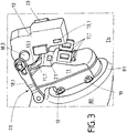
- FIGS. 1 to 3 a first embodiment of the adjusting device 10 according to the invention is shown.
- a protective element 12 is shown by the adjusting device 10 in its opening position IIb, in which a functional unit 15 is accessible from the outer region 10.1 of the adjusting device 10.
- the illustrated functional unit 15 is a camera 15.1, which permits image capture via a lens 15.2 and is arranged in the inner region 10.2 of the adjusting device 10.
- the image data acquired by the camera 15.1 can be displayed in a vehicle on a display or monitor.
- the adjusting device 10 may be arranged in particular in the rear region of a vehicle to z. B. to facilitate a reverse drive.
- the adjusting device 10 may itself be fastened to a carrier element 80, wherein the carrier element 80 may be a body part, a rear apron or another attachment of a vehicle.
- the carrier element 80 may be a body part, a rear apron or another attachment of a vehicle.
- an opening 81 may be provided in the carrier element 80.
- a bead 81 may be provided in the support member 80, whereby the adjusting device 10, in particular with its protective element 12 is arranged approximately flush with the surface of the support member 80.
- the protective element 12 remains in its open position IIb, an additional positive and / or frictional connection in the region of the end positions is provided which acts directly or indirectly on the protective element 12.
- the functional unit 15, in particular the camera 15.1 remains in its desired position even on a bumpy road, since it is firmly arranged on an inner side 12.2 of the protective element 12 and follows the movement of the protective element 12.
- the images taken by the camera 15.1 can be forwarded via an electrical line 22 to the vehicle interior.
- An electrical power supply of the adjusting device 10 can take place via the lateral plug 23 on a drive unit 13, in which the drive 14, in particular as an electric motor is arranged.
- the corresponding drive power of the drive 14 is transmitted via the drive mechanism 18 to at least the protective element 12.
- the functional unit 15 may be arranged on a carriage or lever of the drive mechanism 18 and is thus not firmly connected to the protective element 12.
- the protective element 12 of the adjusting device 10 is shown in its closed position IIa and mounting position Ia.
- the mode of operation of the adjusting device 10 will be explained below.
- the drive power from the drive 14 is transmitted via an indicated worm gear 18.5 to an intermediate shaft 18.3 as a rotary motion.
- a sliding block 18.4 is arranged eccentrically, which cooperates with a closed guide 18.12 of a lever-shaped connecting element 18.1 of the drive mechanism 18.
- a rotation of the intermediate shaft 18.3 counterclockwise pushes the lever-shaped connecting element 18.1 down or ensures a clockwise rotation about an axis of rotation 18.21, which provides a fixed pivot point of the connecting element 18.1.
- the connecting element 18.1 is rotatably connected to the further axis of rotation 18:21 of the lever 18.2, for which purpose a corresponding square is provided as a rotationally fixed connection 18.11.
- a corresponding square is provided as a rotationally fixed connection 18.11
- the maximum opening position IIb is limited by a stop between the lever 18.2 and the adjusting device 10.
- the lever-shaped connecting element 18.1 can not turn further clockwise or depressed, otherwise there would be a significant tension of the entire drive mechanism 18.
- the drive 14 can be switched off in the end positions IIa, IIb, respectively, since there is a self-locking gear in the drive mechanism 18, which is realized solely by the worm gear 18.5. Consequently, only one rotation of the drive shaft of the drive 14 can lead to an adjustment of the protective element 12 and not vice versa.
- the protective element 12 is secured by an additional positive and / or frictional connection in the region of the end position IIa and IIb, which from the FIGS. 4a to 6 is still clear.
- FIG. 3 is a three-dimensional view of the adjusting device 10 in a mounting position Ib shown.
- the adjustment device 10 according to the invention has the technical advantage that it is particularly easy to assemble or fasten even with small openings on a support member 80 in the assembled state.
- the Corresponding assembly can take place exclusively on one side of an outer region 10.1 (see the outer side 12.1 of the protective element 12) of the carrier element 80.
- the drive unit 13 is pivoted to the active unit 11, wherein initially an upper holding means 13.1 behind a likewise upper counter holding means 11.1 of the active unit 11 moves or tilts and then lock the lower holding means 13.1 with the corresponding lower counter holding means 13.1 of the active unit 13.
- a buffer 21 is arranged on the housing of the active unit 11 such that this buffer 21 comes to rest between the housings of the active unit 11 and the drive unit 13. Through this buffer 21 it is achieved that the two units 11, 13 are arranged without play and thus rattle-free in the mounting position Ia to each other.
- the adjusting device 10 of the invention via the active unit 11 and designated fasteners 19 attached to the support member 80, but this attachment can only be made when first the adjustment device 10 has been transferred from its mounting position Ib in the mounting position Ia.
- the drive unit 13 the entire mechanical drive power for the adjusting device 10 is generated.
- the functional unit 15 can also be moved synchronously with the protective element 12 or asynchronously via the drive mechanism 18.
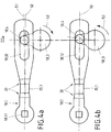
- FIG. 4a is the operation of an additional frictional connection for fixing the protective element in the region of the end positions IIa, IIb shown schematically.
- the lever-shaped connecting element 18.1 is in an approximately horizontal position (s. FIG. 2 , Closing position IIa of the protective element 12), so that the protective element 12 is pressed against a seal 11.2 at one edge of the adjusting device 10 in order to protect the adjusting device 10 reliably against external environmental influences.
- the lever-shaped connecting element 18.1 is in the FIG. 4a at the top dead center purple of the sliding block 18.4 slightly bent, which is indicated by the bending line 51, the above the normal longitudinal axis of the connecting element 18.1 (see also horizontal) is located. So that this deformation or deflection of the connecting element 18.1 can be carried out without damage to the drive mechanism 18, an elastic region 20 is provided on the connecting element 18.1, which is provided in the form of a constriction or cross-sectional tapering 20.1.
- the elastic region 20 can also be realized by a rubber-elastic buffer element, a spring element or the like.
- the protective element 12 is pressed with maximum force against the seal 11.2.
- the adjustment device 10 can be dispensed with an additional latching means 16 and counter-locking means 17, since only the deformable portion 20 assumes the function of generating an additional force in the region of the end position IIa and IIb for the protective element 12.
- the sliding block 18.4 is in its lower position IIIb.
- the sliding block has 18.4 rotated by the intermediate shaft 18.3 by about 170 ° from its upper position purple and is in an approximately 7 o'clock position.
- a deformation of the connecting element takes place 18.1 - as in Fig. 2 and 4a -, But now the connecting element 18.1 is pressed down, so that the corresponding bending line 51 is below the normal longitudinal axis 50 of the connecting element 18.1.
- FIGS. 5a to 5d an additional locking means 16 and a corresponding counter-locking means 17 is used, which cooperates with the drive mechanism 18 in order to produce the additional positive and / or frictional connection for securing the closing element 12 in its end position IIa, IIb.
- the comparable connecting element 18.1 comes from the FIGS. 4a and 4b for use. This can also be bent in the region of the end position Ia, Ib in order to securely hold or fix the protective element 12 in its end position IIa, IIb.
- the deformation of the lever-shaped connecting element 18.1 is only optional to the additional locking 16 and counter-locking means 17 conceivable.
- FIG. 18.1 is only optional to the additional locking 16 and counter-locking means 17 conceivable.
- a locking means 16 which consists of a spherical projection 16.1 and a spring 16.2.
- a spring 16.2 of the spherical projection 16.1 is pressed against the circular edge of the intermediate shaft 18.3.
- a spherical recess 17.1 is provided as a counter-locking means 17.
- the intermediate shaft 18.3 in its upper position purple but the locking means 16 is not yet forms an additional positive and / or frictional connection with the counter-locking means 17.
- FIGS. 5c and 5d Alternative embodiments of the locking means 16 and counter-locking means 17 are shown.
- FIG. 5c is a kinematic reversal to the locking means 16 and counter-locking means 17 from the FIGS. 5a and 5b shown.
- the locking means 16 is shown as a recess which is loaded by a spring 16.2.
- the counter-locking means 17 on the intermediate shaft 18.3 can be seen as a spherical projection which interacts mechanically with the recess in the latching means 16.
- FIG. 5d a further variant of the locking means 16 and the counter-locking means 17 is shown.
- the counter-locking means 17 substantially corresponds to the recess 17.1 from the FIGS. 5a and 5b ,
- the locking means 16 itself is configured in one piece, so that the projection 16.1 is represented by the spring 16.2 itself.
- This may be z. B. to a leaf spring or leg spring or the like, the form-fitting and / or non-positively cooperates with its projection 16.1 with the recess 17.1 of the counter-locking means.
- FIG. 6 schematically a side view of essential elements of the adjusting device 10 is shown to show a major part of the drive mechanism 18. This also makes it clear once again how the rotary motion of the intermediate shaft 18.3 is transmitted via the sliding block 18.4 to the connecting element 18.1, whereby the lever 18.2 is then adjusted with the protective element 12.
- the locking element 16 acts with a rounded projection 16.1 on the end of the connecting element 18.1, which is directed to the intermediate shaft 18.3.
- a recess 17.1 is provided, which cooperates as a counter-locking means 17 with the locking means 16 positively and non-positively.
- the locking means 16 also has a spring 16.2 for this purpose.
- an actuating element 15.1 indicated which serves to z. As a lock for a tailgate mechanically or electromechanically to operate to open them.
Claims (11)
- Dispositif de réglage (10) pour véhicules ou autres choses de ce genre, avec au moins un élément de protection (12), notamment sous la forme d'un couvercle, pour constituer une zone intérieure (10.2) pouvant être fermée derrière l'élément de protection (12) et avec une unité fonctionnelle (15) en tant que telle qui est disposée derrière l'élément de protection (12) dans la zone intérieure (10.2) et avec au moins un système d'entraînement (14), l'élément de protection (12) pouvant être de ce fait mobile entre au moins deux positions extrêmes (IIa, IIb), notamment dans une position de fermeture (IIa) dans laquelle l'élément de protection (12) ferme la zone intérieure (10.2) et dans une position d'ouverture (IIb) dans laquelle l'élément de protection (12) ouvre la zone intérieure (10.2), l'unité fonctionnelle (15) contenant un ensemble de caméra, un cylindre de fermeture et/ou un élément d'actionnement, l'élément de protection (12) étant en plus fixé par conformité de forme et/ou de force dans la zone des positions extrêmes (IIa, IIb) pour maintenir l'élément de protection (12) dans ces positions IIa, IIb) même sous des effets mécaniques perturbateurs, l'unité fonctionnelle (15) étant fixée fermement à une face intérieure (12.2) par l'élément de protection (12) et suivant un mouvement de l'élément de protection (12).
- Dispositif de réglage (10) selon la revendication précédente, caractérisé en ce que la conformité de forme et/ou de force peut être produite dans la zone des positions extrêmes (IIa, IIb) par un moyen d'encliquetage (16).
- Dispositif de réglage (10) selon l'une quelconque des revendications précédentes, caractérisé en ce que le moyen d'encliquetage (16) coopère mécaniquement directement avec l'élément de protection (12), un mécanisme d'entraînement (18) et/ou le système d'entraînement (14).
- Dispositif de réglage (10) selon l'une quelconque des revendications précédentes, caractérisé en ce que le moyen d'encliquetage (16) est constitué en tant qu'élément en saillie faisant ressort (16.1) et coopère avec un moyen opposé d'encliquetage (17) sous la forme d'un évidement (17.1), la conformité de forme et/de force supplémentaire étant de ce fait constituée.
- Dispositif de réglage (10) selon l'une quelconque des revendications précédentes, caractérisé en ce qu'un mécanisme d'entraînement (18) est disposé entre le système d'entraînement (14) et l'élément de protection (12) et la conformité de force supplémentaire peut être produite par une zone élastiquement déformable (20), notamment par le mécanisme d'entraînement (18), le système d'entraînement (14) et/ou l'élément de protection (12).
- Dispositif de réglage (10) selon l'une quelconque des revendications précédentes, caractérisé en ce que le système d'entraînement (14) et/ou le mécanisme d'entraînement (18) est constitué autobloquant de telle sorte qu'un réglage de l'élément de protection (12) n'intervient que par le biais du système d'entraînement (14).
- Dispositif de réglage (10) selon l'une quelconque des revendications précédentes, caractérisé en ce que le mécanisme d'entraînement (18) comporte un élément de liaison (18.1), lequel dispose notamment d'une zone élastique (20).
- Dispositif de réglage (10) selon l'une quelconque des revendications précédentes, caractérisé en ce que la conformité de force supplémentaire doit être surmontée dans la zone des positions extrêmes (IIa, IIb) de l'élément de protection (12) pour parvenir d'une des positions extrêmes (IIa, IIb) aux autres positions extrêmes (IIb, IIa).
- Dispositif de réglage (10) selon l'une quelconque des revendications précédentes, caractérisé en ce qu'au moins le système d'entraînement (14) est disposé pour l'élément de protection (12) dans une unité d'entraînement (13) et l'élément de protection (12) est prévu sur une unité d'activation (11) et en ce que l'unité d'entraînement (12) est constituée pouvant bouger par rapport à l'unité d'activation (11) à l'état monté du dispositif de réglage (10), l'unité d'entraînement (13) étant notamment reliée fermement à l'unité d'activation (11) dans une position de fixation (la).
- Dispositif de réglage (10) selon l'une quelconque des revendications précédentes, caractérisé en ce que l'unité d'entraînement (13) est reliée mécaniquement à l'unité d'activation (11) par au moins une partie du mécanisme d'entraînement (18), notamment par l'élément de liaison (18.1) pour transmettre la puissance motrice du système d'entraînement (14) à l'élément de protection (12).
- Procédé pour faire fonctionner un dispositif de réglage (10) selon l'une quelconque des revendications 1 à 10 pour véhicules ou autres choses de ce genre, avec au moins un élément de protection (12), notamment sous la forme d'un couvercle, pour constituer une zone intérieure (10.2) pouvant être fermée derrière l'élément de protection (12) et avec une unité fonctionnelle (15), qui est disposée dans la zone intérieure (10.2) derrière l'élément de protection (12) et avec au moins un système d'entraînement (14), l'élément de protection (12) pouvant être de ce fait bougé entre au moins deux positions extrêmes (IIa, IIb), notamment dans une position de fermeture (IIa), dans laquelle l'élément de protection (12) ferme la zone intérieure (10.2) et dans une position d'ouverture (IIb) dans laquelle l'élément de protection (12) ouvre la zone intérieure (10.2), caractérisé en ce que l'élément de protection (12) est fixé en plus par conformité de forme et/ou de force dans la zone des positions extrêmes (IIa, IIb) pour maintenir l'élément de protection (12) dans ces positions extrêmes (IIa, IIb) même sous des effets mécaniques pertubateurs.
Applications Claiming Priority (2)
| Application Number | Priority Date | Filing Date | Title |
|---|---|---|---|
| DE102010060610A DE102010060610A1 (de) | 2010-11-16 | 2010-11-16 | Gesicherte Verstellvorrichtung |
| PCT/EP2011/070270 WO2012066046A1 (fr) | 2010-11-16 | 2011-11-16 | Dispositif de réglage protégé |
Publications (2)
| Publication Number | Publication Date |
|---|---|
| EP2640606A1 EP2640606A1 (fr) | 2013-09-25 |
| EP2640606B1 true EP2640606B1 (fr) | 2018-01-10 |
Family
ID=45033950
Family Applications (1)
| Application Number | Title | Priority Date | Filing Date |
|---|---|---|---|
| EP11787823.1A Not-in-force EP2640606B1 (fr) | 2010-11-16 | 2011-11-16 | Dispositif de réglage sécurisé |
Country Status (3)
| Country | Link |
|---|---|
| EP (1) | EP2640606B1 (fr) |
| DE (1) | DE102010060610A1 (fr) |
| WO (1) | WO2012066046A1 (fr) |
Families Citing this family (1)
| Publication number | Priority date | Publication date | Assignee | Title |
|---|---|---|---|---|
| DE102015013315A1 (de) * | 2015-10-14 | 2017-04-20 | GM Global Technology Operations LLC (n. d. Ges. d. Staates Delaware) | Fahrzeug mit Kameraeinheit |
Citations (1)
| Publication number | Priority date | Publication date | Assignee | Title |
|---|---|---|---|---|
| FR2493780A1 (fr) * | 1980-11-13 | 1982-05-14 | Daimler Benz Ag | Dispositif destine a materialiser au moins une partie de l'encombrement d'un vehicule pour aider a l'orientation lors d'un stationnement ou d'une manoeuvre, en particulier pour des vehicules automobiles |
Family Cites Families (3)
| Publication number | Priority date | Publication date | Assignee | Title |
|---|---|---|---|---|
| FR2858280B1 (fr) * | 2003-07-29 | 2008-12-26 | Valeo Systemes Dessuyage | Dispositif de vision arriere pour vehicule automobile |
| DE10351363A1 (de) | 2003-11-04 | 2005-06-09 | Hella Kgaa Hueck & Co. | Kameraanordnung für Kraftfahrzeuge |
| DE102005052031B4 (de) * | 2005-10-31 | 2015-03-12 | Robert Bosch Gmbh | Klappbare Anzeigeeinrichtung mit Abdeckung, insbesondere für Kraftfahrzeuge |
-
2010
- 2010-11-16 DE DE102010060610A patent/DE102010060610A1/de not_active Ceased
-
2011
- 2011-11-16 WO PCT/EP2011/070270 patent/WO2012066046A1/fr active Application Filing
- 2011-11-16 EP EP11787823.1A patent/EP2640606B1/fr not_active Not-in-force
Patent Citations (1)
| Publication number | Priority date | Publication date | Assignee | Title |
|---|---|---|---|---|
| FR2493780A1 (fr) * | 1980-11-13 | 1982-05-14 | Daimler Benz Ag | Dispositif destine a materialiser au moins une partie de l'encombrement d'un vehicule pour aider a l'orientation lors d'un stationnement ou d'une manoeuvre, en particulier pour des vehicules automobiles |
Also Published As
| Publication number | Publication date |
|---|---|
| EP2640606A1 (fr) | 2013-09-25 |
| WO2012066046A1 (fr) | 2012-05-24 |
| DE102010060610A1 (de) | 2012-05-16 |
Similar Documents
| Publication | Publication Date | Title |
|---|---|---|
| EP2673168B1 (fr) | Ensemble de montage pour le montage simplifié sur un véhicule | |
| EP2214931B1 (fr) | Dispositif doté d'une unité caméra | |
| EP2673169B1 (fr) | Agencement de camera pour un véhicule et la méthode pour l'installation | |
| EP2640608B1 (fr) | Dispositif de protection antivol pour un ensemble caméra | |
| EP2796324B1 (fr) | Dispositif doté d'une caméra | |
| EP2414197B1 (fr) | Dispositif avec une camera pour prendre d'images sur l'extérieur d'un véhicule | |
| DE102005052031B4 (de) | Klappbare Anzeigeeinrichtung mit Abdeckung, insbesondere für Kraftfahrzeuge | |
| EP3037683B1 (fr) | Entrainement d'aide à la fermeture pour une serrure de véhicule automobile | |
| DE202011050412U1 (de) | Tankdeckeleinheit für ein Kraftfahrzeug | |
| EP3526080B1 (fr) | Module caméra | |
| DE102010001196A9 (de) | Vereinfachte Vorrichtung einer Kameraeinheit eines Kraftfahrzeugs | |
| DE102012109611A1 (de) | Vorrichtung zur Aufnahme einer Kamera mit vier Gelenken | |
| DE102015102726A1 (de) | Anordnung für ein Fahrzeug | |
| DE102012109610A1 (de) | Vorrichtung zur Aufnahme einer Kamera mit einer Kulisse | |
| DE102012025626A1 (de) | Vorrichtung zur Aufnahme einer Kamera mit vier Gelenken | |
| DE202009016813U1 (de) | Antriebsvorrichtung für ein Ausstellelement eines Kraftfahrzeugs | |
| EP2640606B1 (fr) | Dispositif de réglage sécurisé | |
| EP3196393A1 (fr) | Porte battante comprenant un dispositif de verrouillage à arc-boutement | |
| EP3576987A1 (fr) | Dispositif pour un véhicule automobile | |
| DE102008059918A1 (de) | Montagemodul | |
| EP1362733B1 (fr) | Porte d'obturation d'embout de remplissage | |
| DE10116739B4 (de) | Kraftfahrzeugschließvorrichtung mit Welle als Kupplungsmittel | |
| DE102010060608B4 (de) | Verstellvorrichtung | |
| EP3059126B1 (fr) | Dispositif de camera pour un vehicule | |
| DE102015117775A1 (de) | Kameraeinrichtung für Kraftfahrzeuge |
Legal Events
| Date | Code | Title | Description |
|---|---|---|---|
| PUAI | Public reference made under article 153(3) epc to a published international application that has entered the european phase |
Free format text: ORIGINAL CODE: 0009012 |
|
| 17P | Request for examination filed |
Effective date: 20130514 |
|
| AK | Designated contracting states |
Kind code of ref document: A1 Designated state(s): AL AT BE BG CH CY CZ DE DK EE ES FI FR GB GR HR HU IE IS IT LI LT LU LV MC MK MT NL NO PL PT RO RS SE SI SK SM TR |
|
| DAX | Request for extension of the european patent (deleted) | ||
| 17Q | First examination report despatched |
Effective date: 20150331 |
|
| GRAP | Despatch of communication of intention to grant a patent |
Free format text: ORIGINAL CODE: EPIDOSNIGR1 |
|
| GRAS | Grant fee paid |
Free format text: ORIGINAL CODE: EPIDOSNIGR3 |
|
| INTG | Intention to grant announced |
Effective date: 20171005 |
|
| GRAA | (expected) grant |
Free format text: ORIGINAL CODE: 0009210 |
|
| AK | Designated contracting states |
Kind code of ref document: B1 Designated state(s): AL AT BE BG CH CY CZ DE DK EE ES FI FR GB GR HR HU IE IS IT LI LT LU LV MC MK MT NL NO PL PT RO RS SE SI SK SM TR |
|
| REG | Reference to a national code |
Ref country code: CH Ref legal event code: EP Ref country code: AT Ref legal event code: REF Ref document number: 962015 Country of ref document: AT Kind code of ref document: T Effective date: 20180115 |
|
| REG | Reference to a national code |
Ref country code: IE Ref legal event code: FG4D Free format text: LANGUAGE OF EP DOCUMENT: GERMAN |
|
| REG | Reference to a national code |
Ref country code: DE Ref legal event code: R096 Ref document number: 502011013578 Country of ref document: DE |
|
| REG | Reference to a national code |
Ref country code: NL Ref legal event code: MP Effective date: 20180110 |
|
| PG25 | Lapsed in a contracting state [announced via postgrant information from national office to epo] |
Ref country code: NL Free format text: LAPSE BECAUSE OF FAILURE TO SUBMIT A TRANSLATION OF THE DESCRIPTION OR TO PAY THE FEE WITHIN THE PRESCRIBED TIME-LIMIT Effective date: 20180110 |
|
| PG25 | Lapsed in a contracting state [announced via postgrant information from national office to epo] |
Ref country code: ES Free format text: LAPSE BECAUSE OF FAILURE TO SUBMIT A TRANSLATION OF THE DESCRIPTION OR TO PAY THE FEE WITHIN THE PRESCRIBED TIME-LIMIT Effective date: 20180110 Ref country code: LT Free format text: LAPSE BECAUSE OF FAILURE TO SUBMIT A TRANSLATION OF THE DESCRIPTION OR TO PAY THE FEE WITHIN THE PRESCRIBED TIME-LIMIT Effective date: 20180110 Ref country code: CY Free format text: LAPSE BECAUSE OF FAILURE TO SUBMIT A TRANSLATION OF THE DESCRIPTION OR TO PAY THE FEE WITHIN THE PRESCRIBED TIME-LIMIT Effective date: 20180110 Ref country code: HR Free format text: LAPSE BECAUSE OF FAILURE TO SUBMIT A TRANSLATION OF THE DESCRIPTION OR TO PAY THE FEE WITHIN THE PRESCRIBED TIME-LIMIT Effective date: 20180110 Ref country code: NO Free format text: LAPSE BECAUSE OF FAILURE TO SUBMIT A TRANSLATION OF THE DESCRIPTION OR TO PAY THE FEE WITHIN THE PRESCRIBED TIME-LIMIT Effective date: 20180410 Ref country code: FI Free format text: LAPSE BECAUSE OF FAILURE TO SUBMIT A TRANSLATION OF THE DESCRIPTION OR TO PAY THE FEE WITHIN THE PRESCRIBED TIME-LIMIT Effective date: 20180110 |
|
| PG25 | Lapsed in a contracting state [announced via postgrant information from national office to epo] |
Ref country code: BG Free format text: LAPSE BECAUSE OF FAILURE TO SUBMIT A TRANSLATION OF THE DESCRIPTION OR TO PAY THE FEE WITHIN THE PRESCRIBED TIME-LIMIT Effective date: 20180410 Ref country code: IS Free format text: LAPSE BECAUSE OF FAILURE TO SUBMIT A TRANSLATION OF THE DESCRIPTION OR TO PAY THE FEE WITHIN THE PRESCRIBED TIME-LIMIT Effective date: 20180510 Ref country code: GR Free format text: LAPSE BECAUSE OF FAILURE TO SUBMIT A TRANSLATION OF THE DESCRIPTION OR TO PAY THE FEE WITHIN THE PRESCRIBED TIME-LIMIT Effective date: 20180411 Ref country code: LV Free format text: LAPSE BECAUSE OF FAILURE TO SUBMIT A TRANSLATION OF THE DESCRIPTION OR TO PAY THE FEE WITHIN THE PRESCRIBED TIME-LIMIT Effective date: 20180110 Ref country code: SE Free format text: LAPSE BECAUSE OF FAILURE TO SUBMIT A TRANSLATION OF THE DESCRIPTION OR TO PAY THE FEE WITHIN THE PRESCRIBED TIME-LIMIT Effective date: 20180110 Ref country code: PL Free format text: LAPSE BECAUSE OF FAILURE TO SUBMIT A TRANSLATION OF THE DESCRIPTION OR TO PAY THE FEE WITHIN THE PRESCRIBED TIME-LIMIT Effective date: 20180110 Ref country code: RS Free format text: LAPSE BECAUSE OF FAILURE TO SUBMIT A TRANSLATION OF THE DESCRIPTION OR TO PAY THE FEE WITHIN THE PRESCRIBED TIME-LIMIT Effective date: 20180110 |
|
| PG25 | Lapsed in a contracting state [announced via postgrant information from national office to epo] |
Ref country code: MT Free format text: LAPSE BECAUSE OF FAILURE TO SUBMIT A TRANSLATION OF THE DESCRIPTION OR TO PAY THE FEE WITHIN THE PRESCRIBED TIME-LIMIT Effective date: 20180110 |
|
| REG | Reference to a national code |
Ref country code: DE Ref legal event code: R097 Ref document number: 502011013578 Country of ref document: DE |
|
| PG25 | Lapsed in a contracting state [announced via postgrant information from national office to epo] |
Ref country code: AL Free format text: LAPSE BECAUSE OF FAILURE TO SUBMIT A TRANSLATION OF THE DESCRIPTION OR TO PAY THE FEE WITHIN THE PRESCRIBED TIME-LIMIT Effective date: 20180110 Ref country code: IT Free format text: LAPSE BECAUSE OF FAILURE TO SUBMIT A TRANSLATION OF THE DESCRIPTION OR TO PAY THE FEE WITHIN THE PRESCRIBED TIME-LIMIT Effective date: 20180110 Ref country code: RO Free format text: LAPSE BECAUSE OF FAILURE TO SUBMIT A TRANSLATION OF THE DESCRIPTION OR TO PAY THE FEE WITHIN THE PRESCRIBED TIME-LIMIT Effective date: 20180110 Ref country code: EE Free format text: LAPSE BECAUSE OF FAILURE TO SUBMIT A TRANSLATION OF THE DESCRIPTION OR TO PAY THE FEE WITHIN THE PRESCRIBED TIME-LIMIT Effective date: 20180110 |
|
| PLBE | No opposition filed within time limit |
Free format text: ORIGINAL CODE: 0009261 |
|
| STAA | Information on the status of an ep patent application or granted ep patent |
Free format text: STATUS: NO OPPOSITION FILED WITHIN TIME LIMIT |
|
| PG25 | Lapsed in a contracting state [announced via postgrant information from national office to epo] |
Ref country code: CZ Free format text: LAPSE BECAUSE OF FAILURE TO SUBMIT A TRANSLATION OF THE DESCRIPTION OR TO PAY THE FEE WITHIN THE PRESCRIBED TIME-LIMIT Effective date: 20180110 Ref country code: DK Free format text: LAPSE BECAUSE OF FAILURE TO SUBMIT A TRANSLATION OF THE DESCRIPTION OR TO PAY THE FEE WITHIN THE PRESCRIBED TIME-LIMIT Effective date: 20180110 Ref country code: SM Free format text: LAPSE BECAUSE OF FAILURE TO SUBMIT A TRANSLATION OF THE DESCRIPTION OR TO PAY THE FEE WITHIN THE PRESCRIBED TIME-LIMIT Effective date: 20180110 Ref country code: SK Free format text: LAPSE BECAUSE OF FAILURE TO SUBMIT A TRANSLATION OF THE DESCRIPTION OR TO PAY THE FEE WITHIN THE PRESCRIBED TIME-LIMIT Effective date: 20180110 |
|
| 26N | No opposition filed |
Effective date: 20181011 |
|
| PG25 | Lapsed in a contracting state [announced via postgrant information from national office to epo] |
Ref country code: SI Free format text: LAPSE BECAUSE OF FAILURE TO SUBMIT A TRANSLATION OF THE DESCRIPTION OR TO PAY THE FEE WITHIN THE PRESCRIBED TIME-LIMIT Effective date: 20180110 |
|
| REG | Reference to a national code |
Ref country code: CH Ref legal event code: PL |
|
| PG25 | Lapsed in a contracting state [announced via postgrant information from national office to epo] |
Ref country code: LU Free format text: LAPSE BECAUSE OF NON-PAYMENT OF DUE FEES Effective date: 20181116 Ref country code: MC Free format text: LAPSE BECAUSE OF FAILURE TO SUBMIT A TRANSLATION OF THE DESCRIPTION OR TO PAY THE FEE WITHIN THE PRESCRIBED TIME-LIMIT Effective date: 20180110 |
|
| REG | Reference to a national code |
Ref country code: BE Ref legal event code: MM Effective date: 20181130 |
|
| REG | Reference to a national code |
Ref country code: IE Ref legal event code: MM4A |
|
| PG25 | Lapsed in a contracting state [announced via postgrant information from national office to epo] |
Ref country code: CH Free format text: LAPSE BECAUSE OF NON-PAYMENT OF DUE FEES Effective date: 20181130 Ref country code: LI Free format text: LAPSE BECAUSE OF NON-PAYMENT OF DUE FEES Effective date: 20181130 |
|
| PG25 | Lapsed in a contracting state [announced via postgrant information from national office to epo] |
Ref country code: IE Free format text: LAPSE BECAUSE OF NON-PAYMENT OF DUE FEES Effective date: 20181116 |
|
| PG25 | Lapsed in a contracting state [announced via postgrant information from national office to epo] |
Ref country code: BE Free format text: LAPSE BECAUSE OF NON-PAYMENT OF DUE FEES Effective date: 20181130 |
|
| REG | Reference to a national code |
Ref country code: AT Ref legal event code: MM01 Ref document number: 962015 Country of ref document: AT Kind code of ref document: T Effective date: 20181116 |
|
| PG25 | Lapsed in a contracting state [announced via postgrant information from national office to epo] |
Ref country code: AT Free format text: LAPSE BECAUSE OF NON-PAYMENT OF DUE FEES Effective date: 20181116 |
|
| PG25 | Lapsed in a contracting state [announced via postgrant information from national office to epo] |
Ref country code: TR Free format text: LAPSE BECAUSE OF FAILURE TO SUBMIT A TRANSLATION OF THE DESCRIPTION OR TO PAY THE FEE WITHIN THE PRESCRIBED TIME-LIMIT Effective date: 20180110 |
|
| PG25 | Lapsed in a contracting state [announced via postgrant information from national office to epo] |
Ref country code: PT Free format text: LAPSE BECAUSE OF FAILURE TO SUBMIT A TRANSLATION OF THE DESCRIPTION OR TO PAY THE FEE WITHIN THE PRESCRIBED TIME-LIMIT Effective date: 20180110 |
|
| PG25 | Lapsed in a contracting state [announced via postgrant information from national office to epo] |
Ref country code: HU Free format text: LAPSE BECAUSE OF FAILURE TO SUBMIT A TRANSLATION OF THE DESCRIPTION OR TO PAY THE FEE WITHIN THE PRESCRIBED TIME-LIMIT; INVALID AB INITIO Effective date: 20111116 Ref country code: MK Free format text: LAPSE BECAUSE OF NON-PAYMENT OF DUE FEES Effective date: 20180110 |
|
| PGFP | Annual fee paid to national office [announced via postgrant information from national office to epo] |
Ref country code: FR Payment date: 20201119 Year of fee payment: 10 Ref country code: GB Payment date: 20201123 Year of fee payment: 10 Ref country code: DE Payment date: 20201125 Year of fee payment: 10 |
|
| REG | Reference to a national code |
Ref country code: DE Ref legal event code: R119 Ref document number: 502011013578 Country of ref document: DE |
|
| GBPC | Gb: european patent ceased through non-payment of renewal fee |
Effective date: 20211116 |
|
| PG25 | Lapsed in a contracting state [announced via postgrant information from national office to epo] |
Ref country code: GB Free format text: LAPSE BECAUSE OF NON-PAYMENT OF DUE FEES Effective date: 20211116 Ref country code: DE Free format text: LAPSE BECAUSE OF NON-PAYMENT OF DUE FEES Effective date: 20220601 |
|
| PG25 | Lapsed in a contracting state [announced via postgrant information from national office to epo] |
Ref country code: FR Free format text: LAPSE BECAUSE OF NON-PAYMENT OF DUE FEES Effective date: 20211130 |