EP3059126B1 - Dispositif de camera pour un vehicule - Google Patents
Dispositif de camera pour un vehicule Download PDFInfo
- Publication number
- EP3059126B1 EP3059126B1 EP16154182.6A EP16154182A EP3059126B1 EP 3059126 B1 EP3059126 B1 EP 3059126B1 EP 16154182 A EP16154182 A EP 16154182A EP 3059126 B1 EP3059126 B1 EP 3059126B1
- Authority
- EP
- European Patent Office
- Prior art keywords
- camera unit
- support element
- arrangement
- rest position
- movement
- Prior art date
- Legal status (The legal status is an assumption and is not a legal conclusion. Google has not performed a legal analysis and makes no representation as to the accuracy of the status listed.)
- Active
Links
- 230000033001 locomotion Effects 0.000 claims description 71
- 230000008859 change Effects 0.000 claims description 10
- 238000006073 displacement reaction Methods 0.000 claims description 5
- 230000036316 preload Effects 0.000 claims 2
- 230000008878 coupling Effects 0.000 description 9
- 238000010168 coupling process Methods 0.000 description 9
- 238000005859 coupling reaction Methods 0.000 description 9
- 230000008093 supporting effect Effects 0.000 description 6
- 230000008901 benefit Effects 0.000 description 5
- 238000005452 bending Methods 0.000 description 4
- 238000001514 detection method Methods 0.000 description 4
- 230000000694 effects Effects 0.000 description 4
- 238000000034 method Methods 0.000 description 4
- 230000008569 process Effects 0.000 description 4
- 230000009977 dual effect Effects 0.000 description 3
- 230000006835 compression Effects 0.000 description 2
- 238000007906 compression Methods 0.000 description 2
- 238000011161 development Methods 0.000 description 2
- 230000018109 developmental process Effects 0.000 description 2
- 238000009434 installation Methods 0.000 description 2
- 230000001419 dependent effect Effects 0.000 description 1
- 230000002349 favourable effect Effects 0.000 description 1
- 238000003384 imaging method Methods 0.000 description 1
- 238000004519 manufacturing process Methods 0.000 description 1
- 238000012986 modification Methods 0.000 description 1
- 230000004048 modification Effects 0.000 description 1
- 230000035939 shock Effects 0.000 description 1
Images


Classifications
-
- B—PERFORMING OPERATIONS; TRANSPORTING
- B60—VEHICLES IN GENERAL
- B60R—VEHICLES, VEHICLE FITTINGS, OR VEHICLE PARTS, NOT OTHERWISE PROVIDED FOR
- B60R11/00—Arrangements for holding or mounting articles, not otherwise provided for
- B60R11/04—Mounting of cameras operative during drive; Arrangement of controls thereof relative to the vehicle
-
- B—PERFORMING OPERATIONS; TRANSPORTING
- B60—VEHICLES IN GENERAL
- B60R—VEHICLES, VEHICLE FITTINGS, OR VEHICLE PARTS, NOT OTHERWISE PROVIDED FOR
- B60R11/00—Arrangements for holding or mounting articles, not otherwise provided for
- B60R2011/0094—Arrangements for holding or mounting articles, not otherwise provided for characterised by means for covering after user, e.g. boxes, shutters or the like
Definitions
- the invention is directed to an arrangement for a tailgate of a vehicle, comprising a carrier housing which is to be arranged in a breakthrough of an outer panel of the vehicle, a drive unit which is attached to the carrier housing, a movably mounted camera unit which is received on the carrier housing and with the drive unit is coupled to be moved at least between a rest position and an active position, in which an ambient region of the vehicle is detected, a mounted on the carrier housing actuating element which is movable between a camera unit covering the rest position and an open position and which is suitable for unlocking and / or opening the tailgate, a mechanical restoring element, which is coupled to the actuating element, and a support element, which is coupled to the mechanical restoring element, wherein in the rest position of the camera unit the mechanical restoring element exerts an actuating element in the rest position or urging restoring force on the actuating element and is supported on the support element.
- This arrangement has a dual function, because it serves on the one hand to open a door or flap of the vehicle, to which the actuating element is provided, which is mounted on the carrier housing.
- the arrangement serves to capture the surrounding area of the vehicle, which is indispensable, for example, for a safe Rurteinparken.
- the rearview mirrors only provide the vehicle driver with an insufficient observation area since the rearview mirrors do not allow a view into so-called blind spots.
- Such arrangements include a carrier housing in which the camera unit is movably received between a retracted rest position and an active position.
- the camera unit is movably received between a retracted rest position and an active position.
- the camera unit moves from the rest position to the active position.
- the surrounding area behind the vehicle is captured by the camera unit and displayed on a display for the driver. If the reverse drive is completed and the driver of the vehicle takes the reverse gear out again, the camera unit can be moved from the active position back to the rest position.
- An arrangement according to the preamble of claim 1 is known from DE 10 2006 039 192 A1 and comprises an actuating element for opening a door or flap and a camera unit which serves to capture the image of the exterior of a vehicle.
- the actuator is coupled in this arrangement with a mechanical return element.
- the return element imposes a restoring force on the actuating element, as a result of which the actuating element is held or forced into its rest position. With the help of the return element, the actuating element thus moves automatically back to its rest position, in which it covers the camera unit.
- the restoring force of the restoring element avoids unwanted clattering of the actuating element while driving.
- the actuating element passes with the help of the camera unit or the drive unit from its rest position to its operating position by the actuator is simultaneously adjusted during movement of the camera unit from the rest position to the active position.
- the drive unit must therefore be able to apply a greater force than the restoring force to the actuator to move from its rest position. It should be noted that due to the function of serving for opening actuator, the restoring force must not only be sized so that rattling noises are avoided.
- the invention has for its object to provide a solution that provides a structurally simple way an arrangement for a vehicle that is inexpensive to manufacture and in which the above-mentioned disadvantages are eliminated.
- an arrangement is to be provided, which is characterized by a small space and which can be operated with low energy or energy-efficient.
- the object is achieved in that the support member is movable relative to the carrier housing and that the drive unit is coupled to the support member.
- Coupled means an operative connection, by which, for example, the drive unit directly or indirectly via another component causes a movement of the support member, wherein the operative connection may be mechanical or electrical type.
- the invention provides an arrangement of a tailgate of a vehicle is provided, which is characterized by a functional design.
- Such an arrangement for a vehicle with a movably mounted camera unit and an actuator for opening and / or unlocking a door or flap of the vehicle is simple and inexpensive and ensures in the rest position of the actuator safe protection of the camera unit from external influences, such as Dirt, shocks or blows, which also unintentional opening of the actuating element due to centrifugal forces acting on the actuating element in the event of a vehicle accident, is effectively prevented by the invention.
- the arrangement according to the invention has a dual function, namely the detection of the vehicle environment and the opening and / or unlocking of a flap or door of the vehicle, which is why the arrangement alternatively be referred to as a detection operation arrangement or as a camera unit with integrated actuator or as an actuation or handle assembly with integrated camera unit can.
- the drive unit is coupled to the support element and that the support element is designed to be movable relative to the carrier housing, the support element is displaced when the drive unit moves the camera unit from the rest position to the active position.
- the invention causes a change in position of the support member in the movement of the camera unit from the rest position to the active position, that at the same time the actuator can move to its open position, without this movement must be performed against the restoring force.
- the support of the return element also changes, which ultimately leads to the actuator in a movement of the camera unit from the rest position in the active position is moved by the drive unit powerless and is moved accordingly without significant additional effort from its rest position to its open position.
- Powerless in this context means that in the above movement of the actuating element, the restoring force does not have to be overcome. Consequently, the drive unit only has to use the force required to adjust the camera unit and the support element.
- the restoring force must be overcome only when the camera unit is arranged in its rest position and the actuator for unlocking and / or opening the tailgate is operated by a user.
- the invention provides that in the rest position of the camera unit, the actuating element against the restoring force applied by the restoring element is movable into the open position, which is suitable for unlocking and / or opening the tailgate.
- This has the advantage that the actuating element automatically moves back into the rest position when the manual actuation of the actuating element is completed. Consequently, no additional or larger-sized drive unit is required for the return, so that neither space nor additional energy for an additional drive must be applied.
- the invention provides in an embodiment that the support element between a basic position in which the camera unit is arranged in the rest position, and an operating position in which the camera unit is arranged in the active position, is designed to be movable.
- the coupling of the various positions of the support member to the two camera positions has the advantage that above the support member is coupled to the drive unit. With the aid of the drive unit with which the support element is coupled, it is possible that the support element is movable relative to the carrier housing.
- motion of the camera unit caused by the drive unit may be associated with movement of the support member, wherein a change in the arrangement of the support member relative to the support housing results in a change in the relative location of the support member to the actuator, which in turn causes the camera unit to move Effectiveness of the restoring force changes.
- the restoring force, by which the actuating element is urged into the rest position, is only effective when the support element is arranged in the rest position.
- the mechanical restoring element comprises an elastic spring element.
- the elastic spring element is compressed upon actuation of the actuating element, whereby the restoring force is effective, which acts on the actuating element and urges it into the rest position.
- the spring element in the basic position of the support element and in the rest position of the actuating element, the spring element is relaxed or under one the actuating element in his rest position holding bias is.
- the spring element is when it is relaxed to Example not claimed to bending when the actuator in the rest position and the camera unit are arranged in the rest position, but other types of stress on the spring element are possible.
- the spring element can also be under a bias, which prevents the actuator to move during its positioning in the rest position and generate rattling noises.
- the support member in the rest position of the camera unit, the support member is held in the basic position such that in the open position of the actuating element, the spring element is elastically compressed due to a relative displacement of the actuating element to the support element.
- the spring element is thus compressed upon actuation of the actuating element for unlocking and / or opening a door or tailgate by one of the restoring force of the spring element counteracting force, which is in particular greater than the restoring force is applied.
- the support member when the support member is pivotally mounted on the carrier housing, wherein the support member is held by a holding force which is greater than the restoring force of the elastic spring element, in the basic position.
- a holding force that is greater than the restoring force is required so that the support element continues to have its supporting effect when the actuating element is actuated and is not forced out of its basic position by the restoring element.
- the necessary holding force can be applied, for example, the drive unit, which can act as a kind of engine brake when the camera unit is arranged in its rest position and does not need to be moved.
- the measure has the effect that the support element is pivotable about an axle mounted on the carrier housing, wherein the support element further comprises a first lever arm, on which a contact surface for the elastic spring element and one with an on the actuating element trained movement path of cooperating movement pins are formed.
- the support member When the support member is disposed in the home position, it provides a support surface on which the return member is supported, which is pressed by the actuator when actuated by a user against the support member.
- the support member moves from the home position to the operative position, then the moving pin of the support member pulls the actuator in its open position, without causing the spring element is compressed or would have to be processed against the restoring force, because the contact surface for the return element moves with the support element.
- An advantage for a safely guided movement is when the elastic spring element urges the movement pin in the movement path. A movement of the actuating element or the support element is thus controlled.
- the invention provides in an embodiment that the first lever arm of the support element or a second lever arm of the support element is motion-coupled to the drive unit, wherein the support element is preferably motion-coupled to the drive unit via the camera unit.
- the drive unit is only a single drive unit is required to both move the camera and to pivot the actuator. Because the pivoting of the actuating element from the rest position to the open position is largely powerless or because you do not have to work against the restoring force of the return element, a drive unit with low drive power can be used, which is both inexpensive and takes up little installation space.
- the invention provides in a further embodiment that the actuating element is pivotable about a mounted on the support housing pivot axis between the rest position and the open position, wherein upon movement into the operating position of the movement pin so abuts an end point or an end surface of the movement path of the support member that the movement pin of the support element at a Movement of the support member from the basic position into the operating position pulls the actuator in its open position.
- This entrainment is referred to as powerless entrainment in the context of the invention, since the drive unit must apply no noticeable additional force to pivot the actuator in the open position, because it must not be worked against the restoring force of the return element due to the change in position of the support element according to the invention. It should be noted that despite powerless entrainment the spring element always pushes the movement pin in the movement path.
- the arrangement can be installed as space-saving as possible on the vehicle, it is of further advantage if the pivot axis is at the same time also the supporting element supporting axis. In this way, the installation space for a further axis can be saved.
- the invention provides in an embodiment that does not change in a movement of the camera unit from the rest position to the active position, the relative arrangement or positioning of contact surface of the first lever arm to the actuating element, so that the spring element both during movement of Camera unit is relaxed from the rest position to the active position and in the operating position of the support member and in the open position of the actuating element or is under a relative positioning of abutment surface to actuator holding bias.
- the invention provides in development that the second lever arm is designed as a flap element, which covers the camera unit in the basic position of the support element and which is arranged in the operating position of the support element pivoted about the pivot axis, that the camera unit movable to the active position is to capture a surrounding area of the vehicle.
- the actuator covers the camera unit then, if it is unconfirmed and is arranged in its rest position.
- FIG. 1 is a vehicle 1 in the form of a car exemplified, which in the example has a flap or tailgate 2, to which an arrangement 3 is mounted according to the invention.
- the arrangement according to the invention 3 has a dual function, namely the detection of the vehicle environment and the opening and / or unlocking of the flap 2, which is why the arrangement can alternatively be referred to as detection operation arrangement or as a camera unit with integrated actuator or as an actuation or handle assembly with integrated camera unit.
- the assembly 3 is placed in a breakthrough 4 of the outer panel of the vehicle 1 and secured there, as in particular FIG. 2 shows.
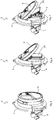
- FIG. 3 is an individual perspective view to see from which the individual components of the assembly 3 can be seen.
- the arrangement 3 comprises a carrier housing 5, on which a Actuator 6 is mounted, which is designed to be movable between a rest position and an open position.
- the actuating element 6 is pivotable about a mounted on the support housing 5 pivot axis 7 between the rest position and the open position, wherein the actuating element 6 in the Figures 2 . 6 . 7 . 9 . 10 . 12 and 13 is arranged in the open position.
- the carrier housing 5 For supporting the pivot axis 7, the carrier housing 5 corresponding bearing points 10, in which the pivot axis 7 is rotatably supported.
- the actuator 6 is suitable for unlocking and / or opening the tailgate 2, as will be discussed in more detail below.
- the arrangement 3 further comprises a mounted on the support housing 5 drive unit 8 and a movably mounted camera unit 9, which is accommodated on the support housing 5 and coupled to the drive unit 8.
- the drive unit 8 and the camera unit 9 are designed as a module 12 that is fastened to the rear side 11 of the carrier housing 5.
- the camera unit 9 is at least between a rest position, in the FIGS. 5, 6 . 8, 9 . 11 and 12 is shown, and an active position in the Figures 2 . 7 . 10 and 13 can be seen, movable. In the rest position, the camera unit 9 is arranged retracted in the module 12.
- the drive unit 8 moves the camera unit 9 out of the module 12, as a result of which the camera unit 9 is further guided through a passage opening 24 formed in the carrier housing 5 (see, for example FIG. 3 ) is moved to detect a surrounding area of the vehicle 1 in the active position, which is desirable, for example, in the reverse drive for parking.
- the actuating element 6 covers the camera unit 9 in its rest position, such as, for example, without difficulty FIG. 5 is apparent.
- the arrangement 3 comprises according to FIG. 3 Further, a mechanical return element 14, which serves, the actuating element 6 in its rest position (see, for example FIG. 5 ), in which it the camera unit 9 or the Module 12 and prevents rattling of the actuator 6, or to urge the actuator 6 back to its rest position when the actuator 6 for unlocking and / or opening a door or flap 2 of the vehicle 1 by a user in the open position (see for example FIG. 6 ) is moved.
- the mechanical return element 14 is formed in the illustrated embodiment as an elastic spring element 15.
- the mechanical return element 14 or the elastic spring element 15 is coupled to the actuating element 6. More specifically, the spring element 15 is a leg spring that is subject to bending.
- the axis of the spring element 15 extends around the pivot axis 7 of the actuating element 6, wherein a first leg 15a of the spring element 15 is supported on the actuating element 6, such as for example FIG. 12 is apparent.
- the mechanical return element 14 or the elastic spring element 15 is further coupled to a support element 16. More specifically, the second leg 15b of the spring member 15 is supported on the support member 16 as well as, for example, in FIG FIG. 12 is shown.
- the support element 16 is pivotable by means of an axle 17 mounted on the carrier housing 5, the support element 16 being designed to be movable or pivotable between a basic position and an operating position.
- axle 17 5 For supporting the axle 17 5 further bearing points 25 are provided on the support housing, which are arranged below the bearing points 10 for the pivot axis 7 of the actuating element 6.
- the camera unit 9 In the basic position of the support member 16, the camera unit 9 is arranged in the rest position, which, for example, in the FIGS. 8, 9 . 11 and 12 is shown. What the FIGS.
- the mechanical restoring element 14 or the elastic spring element 15 exerts a restoring force on the actuating element 6, so that the actuating element 6 is held or forced in the rest position when the camera unit 9 in the rest position and the support member 16 are arranged in the normal position ,
- the restoring element 14 or the second leg 15b of the spring element 15 is supported on the support element 16.
- the mechanical restoring element 14 exerts on the actuating element 6 a restoring force holding or urging the actuating element 6 in the rest position.
- the support member 16 is in the FIGS. 8, 9 . 11 and 12 arranged in its basic position. Although the support member 16 is pivotally supported on the support housing 5 via the axis 17, the support member 16 is held by a holding force in its basic position.
- the holding force which holds the support element 16 in its basic position, is greater than the restoring force of the elastic spring element 15. This ensures that in the rest position of the camera unit 9, the actuating element 6 is movable into the open position against the restoring force applied by the restoring element 14, to unlock the tailgate 2 and / or open, which is for example in the FIGS. 6 . 9 and 12 is shown, in which the actuating element 6 is arranged in the open position.
- the actuating element 6 is arranged in the open position.
- the drive unit 8 is coupled to the support element 16, so that the support element 16 is movable relative to the support housing 5.
- the positions (basic position or operating position) of the support element 16 are coupled in the illustrated embodiment to the position of the camera unit 9.
- the coupling or movement coupling of camera unit 9 and support element 16 is, for example, in the illustrated embodiment of the FIGS. 11 and 13 seen.
- Two pivot arms 21 are each provided with two coupling pins 21a and 21b, of which in each case a first coupling pin 21a is rotatably received in laterally formed on the camera unit 9 receiving arms 22, whereas each second coupling pin 21b in corresponding pivot arms 23 which are integrally formed on the support member 16, is received rotatably.
- the support element 16 is arranged in the basic position. If, however, the camera unit 9 is in the active position, then the support member 16 is arranged in the operating position. However, since the movement and position of the camera unit 9 is coupled to the drive unit 8, consequently, the support member 16 is formed movable via the drive unit 8 between the basic position and the operating position.
- the support member 16 has a first lever arm 18.
- the first lever arm 18 is formed with a contact surface 19 and a movement pin 20.
- the contact surface 19 of the support member 16 serves to support the second leg 15b of the spring element 15 on it, which is important when the spring element 15 is compressed or compressed during movement of the actuating element 6 into its open position, which presupposes in that the support element 16 in the basic position and the camera unit are arranged in the rest position.
- This process, in which the return element 14 and the spring element 15 is compressed corresponds to the opening process described in the prior art for doors or tailgates with the aid of a known arrangement, but which has no camera unit.
- abutment surface 19 is formed as part of the support housing 5, so that, as is known, the spring element 15 is supported on the support housing 5.
- a relative movement of a support element 16 or a bearing surface 19 formed on the support element 16 was not provided in these known arrangements.
- the drive unit 8 Due to the fact that the support element 16 with its abutment surface 19 is movable relative to the carrier housing 5, it is possible that the drive unit 8 no longer has to work against the restoring force of the restoring element 14 or spring element 15, for which reason the drive unit 8 is dimensioned correspondingly energy-saving can.
- the drive unit 8 therefore does not have to work against the restoring force, because the relative arrangement of abutment surface 19 of the first lever arm 18 to the actuating element 6 does not change during a movement of the camera unit 9 from the rest position to the active position, as for example from a comparison of the FIGS. 11 and 13 is apparent.
- the support element 16 is moved from the basic position into the operating position.
- This movement of the support member 16 of the movement pin 20 cooperates with a trained on the actuator 6 trajectory 26, such as from the Figures 10 and 13 is apparent.
- the movement path 26 has no significance in a movement of the actuating element 6 in the open position when the support element 16 is arranged in the basic position.
- For the movement pin 20 moves during pivoting of the actuating element 6 within a recess 27, but without interacting with the actuating element 6, which is not at all desirable for an opening or unlocking process.
- the shape and size of the recess 27 play no role in an opening or unlocking process, as long as the movement pin 20 does not interact with the actuating element 6 or with its movement path 26.
- the spring element 15 in this case only causes the movement pin 20 is pressed into the movement path 26.
- the trajectory 26 acquires importance only when the support element 16 is moved from its basic position into the operating position (see FIGS. 7 . 10 and 13 ). Because then the camera unit 9 is extended and should detect the surrounding area of the vehicle 1. For this purpose, however, the actuating element 6 must be moved from the rest position, in which it covers the camera unit 9, in the open position, for which the movement pin 20 of the support member 16 comes into contact with an end face 28 of the movement path 26 during movement into the operating position and thereby on the Actuator 6 pulls. This pulling movement causes the support member 16 pivots the actuator 6 in the open position, without having to work against the restoring force of the return element 6.
- the relaxation angle ⁇ is still between 50 ° and 60 °, so that the movement causes no compression of the elastic spring element 15.
- the actuating element 6 in its open position with a force which is smaller than the restoring force of the return element, pulls.
- the spring element 15 is still under a bias to prevent rattling of the actuating element 6.
- a flap member 29 is provided to cover the camera unit 9, when it is arranged in its rest position, the actuator 6, however, is in its open position.
- a second lever arm 30 is formed on the support member 16, which represents the flap member 29 and the passage opening 24 closes to protect the camera unit 9.
- the flap element 29 covers the camera unit 9 in the basic position of the support element 16.
- the flap element 29 is pivoted about the axis 17 in such a way that the camera unit 9 can be moved to the active position in order to detect a surrounding area of the vehicle 1.
- the first lever arm 18 and the second lever arm 30 converge in the axis 17 and are pivotable about this.
- the pivot arms 23 are formed on the rear side of the flap element 29 of the support element 16, so that in the embodiment shown, the second lever arm 30 is coupled in a motion-coupled manner to the drive unit 8 via the camera unit 9.
- a coupling can also take place via the first lever arm 18, wherein the coupling can take place directly with the drive unit 8 and not via the camera unit 9.
Claims (14)
- Dispositif (3) pour un hayon (2) d'un véhicule (1), avec
un boîtier de support (5) qui doit être disposé dans une ouverture (4) d'un revêtement extérieur du véhicule (1),
une unité d'entraînement (8) aménagée sur le boîtier de support (5),
une unité de caméra (9) montée de façon mobile, laquelle est réceptionnée au niveau du boîtier de support (5) et est accouplée avec l'unité d'entraînement (8) pour pouvoir être déplacée au moins entre une position de repos et une position active dans laquelle une zone environnante du véhicule (1) est détectable,
un élément d'actionnement (6) monté sur le boîtier de support (5), lequel est réalisé de façon mobile entre une position de repos recouvrant l'unité de caméra (9) et une position ouverte et lequel convient pour déverrouiller et/ou ouvrir le hayon (2),
un élément de rappel mécanique (14), lequel est accouplé avec l'élément d'actionnement (6), et
un élément de support (16), lequel est accouplé avec l'élément de rappel mécanique (14),
dans lequel, dans la position de repos de l'unité de caméra (9), l'élément de rappel mécanique (14) exerce une force de rappel sur l'élément d'actionnement (6) maintenant ou poussant l'élément d'actionnement (6) dans la position de repos et est en appui sur l'élément de support (16),
caractérisé en ce que
l'élément de support (16) est mobile par rapport au boîtier de support (5) et que l'unité d'entraînement (8) est accouplée avec l'élément de support (16). - Dispositif (3) selon la revendication 1, caractérisé en ce que, dans la position de repos de l'unité de caméra (9), l'élément d'actionnement (6) peut être déplacé à l'encontre de la force de rappel fournie par l'élément de rappel (14) dans la position ouverte, laquelle convient pour le déverrouillage et/ou l'ouverture du hayon (2).
- Dispositif (3) selon la revendication 1 ou 2, caractérisé en ce que l'élément de support (16) est réalisé de manière mobile entre une position de base dans laquelle l'unité de caméra (9) est disposée en position de repos et une position de fonctionnement dans laquelle l'unité de caméra (9) est disposée dans la positon active.
- Dispositif (3) selon la revendication 3, caractérisé en ce que l'élément de rappel mécanique (14) comprend un élément de ressort élastique (15).
- Dispositif (3) selon la revendication 4, caractérisé en ce que, dans la position de base de l'élément de support (16) et dans la position de repos de l'élément d'actionnement (6), l'élément de ressort (15) est détendu ou est soumis à une précontrainte maintenant l'élément d'actionnement (6) dans sa position de repos.
- Dispositif (3) selon la revendication 4 ou 5, caractérisé en ce que, dans la position de repos de l'unité de caméra (9), l'élément de support (16) est maintenu dans la position de base de manière à ce que l'élément de ressort (15), en position ouverte de l'élément d'actionnement (6), est comprimé élastiquement suite à un déplacement relatif de l'élément d'actionnement (6) par rapport à l'élément de support (16).
- Dispositif (3) selon la revendication 6, caractérisé en ce que l'élément de support (16) est monté de manière pivotante sur le boîtier de support (5), dans lequel l'élément de support (16) est maintenu dans la position de base par une force de maintien qui est supérieure à la force de rappel de l'élément de ressort élastique (15).
- Dispositif (3) selon l'une des revendications 4 à 7, caractérisé en ce que l'élément de support (16) peut pivoter autour d'un axe (17) monté au niveau du boîtier de support (5), dans lequel l'élément de support (16) présente en outre un premier bras de levier (18) sur lequel une surface d'appui (19) pour l'élément de ressort élastique (15) et un téton de déplacement (20) coopérant avec une voie de déplacement (26) réalisée au niveau de l'élément d'actionnement (6) sont formés.
- Dispositif (3) selon la revendication 8, caractérisé en ce que l'élément de ressort élastique (15) pousse le téton de déplacement (20) dans la voie de déplacement (26).
- Dispositif (3) selon la revendication 8 ou 9, caractérisé en ce que l'élément d'actionnement (6) peut pivoter autour d'un axe de pivotement (7) monté sur le boîtier de support (5) entre la position de repos et la position ouverte, dans lequel, en cas d'un déplacement dans la position de fonctionnement, le téton de déplacement (20) repose contre un point d'extrémité ou une surface d'extrémité (28) de la voie de déplacement (26) de l'élément de support (16) de manière à ce que, lors d'un déplacement de l'élément de support (16) de la position de base vers la position de fonctionnement, le téton de déplacement (20) de l'élément de support (16) tire l'élément d'actionnement (6) dans sa position ouverte.
- Dispositif (3) selon la revendication 8, 9 ou 10, caractérisé en ce que l'axe de pivotement (7) est simultanément également l'axe (17) de montage de l'élément de support (16).
- Dispositif (3) selon l'une des revendications 8 à 11, caractérisé en ce que, lors d'un déplacement de l'unité de caméra (9) de la position de repos vers la position active, le positionnement relatif entre la surface d'appui (19) du premier bras de levier (18) et l'élément d'actionnement (6) ne se modifie pas de sorte que l'élément de ressort (15) est détendu pendant le déplacement de l'unité de caméra (9) de la position de repos vers la position active tout comme également dans la position de fonctionnement de l'élément de support (16) et dans la position ouverte de l'élément d'actionnement (6) ou bien est soumis à une précontrainte maintenant le positionnement relatif entre la surface d'appui (19) et l'élément d'actionnement (6).
- Dispositif (3) selon l'une des revendications 8 à 12, caractérisé en ce que le premier bras de levier (18) de l'élément de support (16) ou un deuxième bras de levier (30) de l'élément de support (16) est en accouplement de déplacement avec l'unité d'entraînement (8), dans lequel l'élément de support (16) est de préférence en accouplement de déplacement avec l'unité d'entraînement (8) via l'unité de caméra (9).
- Dispositif (3) selon la revendication 13, caractérisé en ce que le deuxième bras de levier (30) est réalisé en tant qu'un élément formant clapet (29) lequel, dans la position de base de l'élément de support (16), recouvre l'unité de caméra (9) et lequel, dans la position de fonctionnement de l'élément de support (16), est disposé de façon pivotante autour de l'axe (17) de manière à ce que l'unité de caméra (9) est déplaçable dans la position active pour détecter une zone environnante du véhicule (1).
Applications Claiming Priority (2)
| Application Number | Priority Date | Filing Date | Title |
|---|---|---|---|
| DE102015102386 | 2015-02-19 | ||
| DE102015102726.7A DE102015102726A1 (de) | 2015-02-19 | 2015-02-25 | Anordnung für ein Fahrzeug |
Publications (2)
| Publication Number | Publication Date |
|---|---|
| EP3059126A1 EP3059126A1 (fr) | 2016-08-24 |
| EP3059126B1 true EP3059126B1 (fr) | 2017-09-20 |
Family
ID=55315327
Family Applications (1)
| Application Number | Title | Priority Date | Filing Date |
|---|---|---|---|
| EP16154182.6A Active EP3059126B1 (fr) | 2015-02-19 | 2016-02-04 | Dispositif de camera pour un vehicule |
Country Status (1)
| Country | Link |
|---|---|
| EP (1) | EP3059126B1 (fr) |
Cited By (1)
| Publication number | Priority date | Publication date | Assignee | Title |
|---|---|---|---|---|
| CN111439215A (zh) * | 2020-04-03 | 2020-07-24 | 史善军 | 一种后视镜行车记录仪 |
Family Cites Families (4)
| Publication number | Priority date | Publication date | Assignee | Title |
|---|---|---|---|---|
| DE102006039192A1 (de) | 2006-08-22 | 2008-02-28 | Huf Hülsbeck & Fürst Gmbh & Co. Kg | Vorrichtung zum Öffnen eines Fahrzeugschlosses und zur Bilderfassung im Außenbereich vom Fahrzeug |
| DE102008010966B4 (de) * | 2008-02-25 | 2019-11-14 | Volkswagen Ag | Anordnung für ein Fahrzeug mit einer Entriegelungsvorrichtung und einer Kamera |
| DE102010001196A1 (de) * | 2010-01-15 | 2011-07-21 | Huf Hülsbeck & Fürst GmbH & Co. KG, 42551 | Vereinfachte Vorrichtung einer Kameraeinheit eines Kraftfahrzeugs |
| DE102011111854A1 (de) * | 2011-08-27 | 2013-02-28 | Volkswagen Aktiengesellschaft | Schwenkmechanismus zum beweglichen Anbringen einer Kamera an einem Fahrzeug |
-
2016
- 2016-02-04 EP EP16154182.6A patent/EP3059126B1/fr active Active
Non-Patent Citations (1)
| Title |
|---|
| None * |
Cited By (1)
| Publication number | Priority date | Publication date | Assignee | Title |
|---|---|---|---|---|
| CN111439215A (zh) * | 2020-04-03 | 2020-07-24 | 史善军 | 一种后视镜行车记录仪 |
Also Published As
| Publication number | Publication date |
|---|---|
| EP3059126A1 (fr) | 2016-08-24 |
Similar Documents
| Publication | Publication Date | Title |
|---|---|---|
| DE102015102726A1 (de) | Anordnung für ein Fahrzeug | |
| EP2214931B1 (fr) | Dispositif doté d'une unité caméra | |
| DE102006048373A1 (de) | Vorrichtung für ein Kraftfahrzeug mit einer drehbar gelagerten Kameraeinheit | |
| EP2325419A9 (fr) | Poignée de porte de sécurité | |
| EP3292025B1 (fr) | Dispositif avec une camera pour prendre d'images sur l'extérieur d'un véhicule | |
| EP3085582A1 (fr) | Dispositif dote d'une camera et d'un element de recouvrement | |
| EP3455104B1 (fr) | Dispositif comprenant une unité caméra et un élément de recouvrement | |
| DE102017101418A1 (de) | Türgriffanordnung für eine Fahrzeugtür | |
| EP3803005A1 (fr) | Ensemble poignée de porte conçu pour un véhicule automobile | |
| WO2018137819A1 (fr) | Agencement de poignée de porte pour porte de véhicule | |
| WO2018041623A1 (fr) | Poignée extérieure de porte pour un vehicule à moteur | |
| DE102004002213B4 (de) | Fußgängerschutz-Aktuator mit Rückstelleinrichtung | |
| EP2859255B1 (fr) | Frein de stationnement pour une boîte de vitesses d'un véhicule automobile | |
| EP3059126B1 (fr) | Dispositif de camera pour un vehicule | |
| DE102020112935A1 (de) | Kraftfahrzeug-Türgriffanordnung | |
| DE102008024341A1 (de) | Türbetätigungsvorrichtung mit einer Notöffnungseinrichtung | |
| DE102020202146A1 (de) | Lenkhandhabe für ein motorisiertes Fahrzeug | |
| EP3084105B1 (fr) | Serrure pour porte de véhicule | |
| EP3649018A1 (fr) | Dispositif de déplacement de véhicule à moteur | |
| DE202013101518U1 (de) | Vorrichtung zum Anstellen einer Motorhaube | |
| WO2018153799A1 (fr) | Dispositif d'actionnement manuel comprenant un élément d'arrêt | |
| DE102020202144A1 (de) | Lenkhandhabe für ein motorisiertes Fahrzeug | |
| EP3803006A1 (fr) | Ensemble poignée de porte conçu pour un véhicule automobile | |
| DE102004002212B4 (de) | Fußgängerschutz-Aktuator mit Elektromagneten | |
| DE102021130579A1 (de) | Befestigungseinrichtung für ein Display an einer Schalttafel eines Kraftfahrzeugs |
Legal Events
| Date | Code | Title | Description |
|---|---|---|---|
| PUAI | Public reference made under article 153(3) epc to a published international application that has entered the european phase |
Free format text: ORIGINAL CODE: 0009012 |
|
| AK | Designated contracting states |
Kind code of ref document: A1 Designated state(s): AL AT BE BG CH CY CZ DE DK EE ES FI FR GB GR HR HU IE IS IT LI LT LU LV MC MK MT NL NO PL PT RO RS SE SI SK SM TR |
|
| AX | Request for extension of the european patent |
Extension state: BA ME |
|
| 17P | Request for examination filed |
Effective date: 20161017 |
|
| RBV | Designated contracting states (corrected) |
Designated state(s): AL AT BE BG CH CY CZ DE DK EE ES FI FR GB GR HR HU IE IS IT LI LT LU LV MC MK MT NL NO PL PT RO RS SE SI SK SM TR |
|
| GRAP | Despatch of communication of intention to grant a patent |
Free format text: ORIGINAL CODE: EPIDOSNIGR1 |
|
| STAA | Information on the status of an ep patent application or granted ep patent |
Free format text: STATUS: GRANT OF PATENT IS INTENDED |
|
| RIC1 | Information provided on ipc code assigned before grant |
Ipc: B60R 11/04 20060101AFI20170502BHEP |
|
| INTG | Intention to grant announced |
Effective date: 20170524 |
|
| GRAS | Grant fee paid |
Free format text: ORIGINAL CODE: EPIDOSNIGR3 |
|
| GRAA | (expected) grant |
Free format text: ORIGINAL CODE: 0009210 |
|
| STAA | Information on the status of an ep patent application or granted ep patent |
Free format text: STATUS: THE PATENT HAS BEEN GRANTED |
|
| AK | Designated contracting states |
Kind code of ref document: B1 Designated state(s): AL AT BE BG CH CY CZ DE DK EE ES FI FR GB GR HR HU IE IS IT LI LT LU LV MC MK MT NL NO PL PT RO RS SE SI SK SM TR |
|
| REG | Reference to a national code |
Ref country code: GB Ref legal event code: FG4D Free format text: NOT ENGLISH |
|
| REG | Reference to a national code |
Ref country code: CH Ref legal event code: EP |
|
| REG | Reference to a national code |
Ref country code: AT Ref legal event code: REF Ref document number: 929872 Country of ref document: AT Kind code of ref document: T Effective date: 20171015 |
|
| REG | Reference to a national code |
Ref country code: IE Ref legal event code: FG4D Free format text: LANGUAGE OF EP DOCUMENT: GERMAN |
|
| REG | Reference to a national code |
Ref country code: DE Ref legal event code: R096 Ref document number: 502016000146 Country of ref document: DE |
|
| REG | Reference to a national code |
Ref country code: NL Ref legal event code: MP Effective date: 20170920 |
|
| PG25 | Lapsed in a contracting state [announced via postgrant information from national office to epo] |
Ref country code: LT Free format text: LAPSE BECAUSE OF FAILURE TO SUBMIT A TRANSLATION OF THE DESCRIPTION OR TO PAY THE FEE WITHIN THE PRESCRIBED TIME-LIMIT Effective date: 20170920 Ref country code: FI Free format text: LAPSE BECAUSE OF FAILURE TO SUBMIT A TRANSLATION OF THE DESCRIPTION OR TO PAY THE FEE WITHIN THE PRESCRIBED TIME-LIMIT Effective date: 20170920 Ref country code: HR Free format text: LAPSE BECAUSE OF FAILURE TO SUBMIT A TRANSLATION OF THE DESCRIPTION OR TO PAY THE FEE WITHIN THE PRESCRIBED TIME-LIMIT Effective date: 20170920 Ref country code: NO Free format text: LAPSE BECAUSE OF FAILURE TO SUBMIT A TRANSLATION OF THE DESCRIPTION OR TO PAY THE FEE WITHIN THE PRESCRIBED TIME-LIMIT Effective date: 20171220 Ref country code: SE Free format text: LAPSE BECAUSE OF FAILURE TO SUBMIT A TRANSLATION OF THE DESCRIPTION OR TO PAY THE FEE WITHIN THE PRESCRIBED TIME-LIMIT Effective date: 20170920 |
|
| REG | Reference to a national code |
Ref country code: LT Ref legal event code: MG4D |
|
| REG | Reference to a national code |
Ref country code: FR Ref legal event code: PLFP Year of fee payment: 3 |
|
| PG25 | Lapsed in a contracting state [announced via postgrant information from national office to epo] |
Ref country code: LV Free format text: LAPSE BECAUSE OF FAILURE TO SUBMIT A TRANSLATION OF THE DESCRIPTION OR TO PAY THE FEE WITHIN THE PRESCRIBED TIME-LIMIT Effective date: 20170920 Ref country code: BG Free format text: LAPSE BECAUSE OF FAILURE TO SUBMIT A TRANSLATION OF THE DESCRIPTION OR TO PAY THE FEE WITHIN THE PRESCRIBED TIME-LIMIT Effective date: 20171220 Ref country code: RS Free format text: LAPSE BECAUSE OF FAILURE TO SUBMIT A TRANSLATION OF THE DESCRIPTION OR TO PAY THE FEE WITHIN THE PRESCRIBED TIME-LIMIT Effective date: 20170920 Ref country code: GR Free format text: LAPSE BECAUSE OF FAILURE TO SUBMIT A TRANSLATION OF THE DESCRIPTION OR TO PAY THE FEE WITHIN THE PRESCRIBED TIME-LIMIT Effective date: 20171221 |
|
| PG25 | Lapsed in a contracting state [announced via postgrant information from national office to epo] |
Ref country code: NL Free format text: LAPSE BECAUSE OF FAILURE TO SUBMIT A TRANSLATION OF THE DESCRIPTION OR TO PAY THE FEE WITHIN THE PRESCRIBED TIME-LIMIT Effective date: 20170920 |
|
| PG25 | Lapsed in a contracting state [announced via postgrant information from national office to epo] |
Ref country code: CZ Free format text: LAPSE BECAUSE OF FAILURE TO SUBMIT A TRANSLATION OF THE DESCRIPTION OR TO PAY THE FEE WITHIN THE PRESCRIBED TIME-LIMIT Effective date: 20170920 Ref country code: ES Free format text: LAPSE BECAUSE OF FAILURE TO SUBMIT A TRANSLATION OF THE DESCRIPTION OR TO PAY THE FEE WITHIN THE PRESCRIBED TIME-LIMIT Effective date: 20170920 Ref country code: RO Free format text: LAPSE BECAUSE OF FAILURE TO SUBMIT A TRANSLATION OF THE DESCRIPTION OR TO PAY THE FEE WITHIN THE PRESCRIBED TIME-LIMIT Effective date: 20170920 Ref country code: PL Free format text: LAPSE BECAUSE OF FAILURE TO SUBMIT A TRANSLATION OF THE DESCRIPTION OR TO PAY THE FEE WITHIN THE PRESCRIBED TIME-LIMIT Effective date: 20170920 |
|
| PG25 | Lapsed in a contracting state [announced via postgrant information from national office to epo] |
Ref country code: EE Free format text: LAPSE BECAUSE OF FAILURE TO SUBMIT A TRANSLATION OF THE DESCRIPTION OR TO PAY THE FEE WITHIN THE PRESCRIBED TIME-LIMIT Effective date: 20170920 Ref country code: SK Free format text: LAPSE BECAUSE OF FAILURE TO SUBMIT A TRANSLATION OF THE DESCRIPTION OR TO PAY THE FEE WITHIN THE PRESCRIBED TIME-LIMIT Effective date: 20170920 Ref country code: SM Free format text: LAPSE BECAUSE OF FAILURE TO SUBMIT A TRANSLATION OF THE DESCRIPTION OR TO PAY THE FEE WITHIN THE PRESCRIBED TIME-LIMIT Effective date: 20170920 Ref country code: IT Free format text: LAPSE BECAUSE OF FAILURE TO SUBMIT A TRANSLATION OF THE DESCRIPTION OR TO PAY THE FEE WITHIN THE PRESCRIBED TIME-LIMIT Effective date: 20170920 Ref country code: IS Free format text: LAPSE BECAUSE OF FAILURE TO SUBMIT A TRANSLATION OF THE DESCRIPTION OR TO PAY THE FEE WITHIN THE PRESCRIBED TIME-LIMIT Effective date: 20180120 |
|
| REG | Reference to a national code |
Ref country code: DE Ref legal event code: R097 Ref document number: 502016000146 Country of ref document: DE |
|
| PLBE | No opposition filed within time limit |
Free format text: ORIGINAL CODE: 0009261 |
|
| STAA | Information on the status of an ep patent application or granted ep patent |
Free format text: STATUS: NO OPPOSITION FILED WITHIN TIME LIMIT |
|
| PG25 | Lapsed in a contracting state [announced via postgrant information from national office to epo] |
Ref country code: DK Free format text: LAPSE BECAUSE OF FAILURE TO SUBMIT A TRANSLATION OF THE DESCRIPTION OR TO PAY THE FEE WITHIN THE PRESCRIBED TIME-LIMIT Effective date: 20170920 |
|
| 26N | No opposition filed |
Effective date: 20180621 |
|
| PG25 | Lapsed in a contracting state [announced via postgrant information from national office to epo] |
Ref country code: MT Free format text: LAPSE BECAUSE OF FAILURE TO SUBMIT A TRANSLATION OF THE DESCRIPTION OR TO PAY THE FEE WITHIN THE PRESCRIBED TIME-LIMIT Effective date: 20170920 Ref country code: MC Free format text: LAPSE BECAUSE OF FAILURE TO SUBMIT A TRANSLATION OF THE DESCRIPTION OR TO PAY THE FEE WITHIN THE PRESCRIBED TIME-LIMIT Effective date: 20170920 |
|
| REG | Reference to a national code |
Ref country code: IE Ref legal event code: MM4A |
|
| REG | Reference to a national code |
Ref country code: BE Ref legal event code: MM Effective date: 20180228 |
|
| PG25 | Lapsed in a contracting state [announced via postgrant information from national office to epo] |
Ref country code: SI Free format text: LAPSE BECAUSE OF FAILURE TO SUBMIT A TRANSLATION OF THE DESCRIPTION OR TO PAY THE FEE WITHIN THE PRESCRIBED TIME-LIMIT Effective date: 20170920 Ref country code: LU Free format text: LAPSE BECAUSE OF NON-PAYMENT OF DUE FEES Effective date: 20180204 |
|
| PG25 | Lapsed in a contracting state [announced via postgrant information from national office to epo] |
Ref country code: IE Free format text: LAPSE BECAUSE OF NON-PAYMENT OF DUE FEES Effective date: 20180204 |
|
| PG25 | Lapsed in a contracting state [announced via postgrant information from national office to epo] |
Ref country code: BE Free format text: LAPSE BECAUSE OF NON-PAYMENT OF DUE FEES Effective date: 20180228 |
|
| REG | Reference to a national code |
Ref country code: CH Ref legal event code: PL |
|
| PG25 | Lapsed in a contracting state [announced via postgrant information from national office to epo] |
Ref country code: CH Free format text: LAPSE BECAUSE OF NON-PAYMENT OF DUE FEES Effective date: 20190228 Ref country code: LI Free format text: LAPSE BECAUSE OF NON-PAYMENT OF DUE FEES Effective date: 20190228 |
|
| PG25 | Lapsed in a contracting state [announced via postgrant information from national office to epo] |
Ref country code: TR Free format text: LAPSE BECAUSE OF FAILURE TO SUBMIT A TRANSLATION OF THE DESCRIPTION OR TO PAY THE FEE WITHIN THE PRESCRIBED TIME-LIMIT Effective date: 20170920 |
|
| PGFP | Annual fee paid to national office [announced via postgrant information from national office to epo] |
Ref country code: DE Payment date: 20200229 Year of fee payment: 5 |
|
| PG25 | Lapsed in a contracting state [announced via postgrant information from national office to epo] |
Ref country code: PT Free format text: LAPSE BECAUSE OF FAILURE TO SUBMIT A TRANSLATION OF THE DESCRIPTION OR TO PAY THE FEE WITHIN THE PRESCRIBED TIME-LIMIT Effective date: 20170920 |
|
| PG25 | Lapsed in a contracting state [announced via postgrant information from national office to epo] |
Ref country code: CY Free format text: LAPSE BECAUSE OF FAILURE TO SUBMIT A TRANSLATION OF THE DESCRIPTION OR TO PAY THE FEE WITHIN THE PRESCRIBED TIME-LIMIT Effective date: 20170920 Ref country code: HU Free format text: LAPSE BECAUSE OF FAILURE TO SUBMIT A TRANSLATION OF THE DESCRIPTION OR TO PAY THE FEE WITHIN THE PRESCRIBED TIME-LIMIT; INVALID AB INITIO Effective date: 20160204 Ref country code: MK Free format text: LAPSE BECAUSE OF NON-PAYMENT OF DUE FEES Effective date: 20170920 |
|
| PGFP | Annual fee paid to national office [announced via postgrant information from national office to epo] |
Ref country code: FR Payment date: 20200220 Year of fee payment: 5 |
|
| PG25 | Lapsed in a contracting state [announced via postgrant information from national office to epo] |
Ref country code: AL Free format text: LAPSE BECAUSE OF FAILURE TO SUBMIT A TRANSLATION OF THE DESCRIPTION OR TO PAY THE FEE WITHIN THE PRESCRIBED TIME-LIMIT Effective date: 20170920 |
|
| REG | Reference to a national code |
Ref country code: DE Ref legal event code: R119 Ref document number: 502016000146 Country of ref document: DE |
|
| PG25 | Lapsed in a contracting state [announced via postgrant information from national office to epo] |
Ref country code: DE Free format text: LAPSE BECAUSE OF NON-PAYMENT OF DUE FEES Effective date: 20210901 Ref country code: FR Free format text: LAPSE BECAUSE OF NON-PAYMENT OF DUE FEES Effective date: 20210228 |
|
| REG | Reference to a national code |
Ref country code: AT Ref legal event code: MM01 Ref document number: 929872 Country of ref document: AT Kind code of ref document: T Effective date: 20210204 |
|
| PG25 | Lapsed in a contracting state [announced via postgrant information from national office to epo] |
Ref country code: AT Free format text: LAPSE BECAUSE OF NON-PAYMENT OF DUE FEES Effective date: 20210204 |
|
| PGFP | Annual fee paid to national office [announced via postgrant information from national office to epo] |
Ref country code: GB Payment date: 20240222 Year of fee payment: 9 |