EP2640606B1 - Secured adjusting deivce - Google Patents
Secured adjusting deivce Download PDFInfo
- Publication number
- EP2640606B1 EP2640606B1 EP11787823.1A EP11787823A EP2640606B1 EP 2640606 B1 EP2640606 B1 EP 2640606B1 EP 11787823 A EP11787823 A EP 11787823A EP 2640606 B1 EP2640606 B1 EP 2640606B1
- Authority
- EP
- European Patent Office
- Prior art keywords
- protective element
- drive
- iib
- iia
- adjustment device
- Prior art date
- Legal status (The legal status is an assumption and is not a legal conclusion. Google has not performed a legal analysis and makes no representation as to the accuracy of the status listed.)
- Not-in-force
Links
Images


Classifications
-
- B—PERFORMING OPERATIONS; TRANSPORTING
- B60—VEHICLES IN GENERAL
- B60R—VEHICLES, VEHICLE FITTINGS, OR VEHICLE PARTS, NOT OTHERWISE PROVIDED FOR
- B60R11/00—Arrangements for holding or mounting articles, not otherwise provided for
- B60R11/04—Mounting of cameras operative during drive; Arrangement of controls thereof relative to the vehicle
-
- G—PHYSICS
- G03—PHOTOGRAPHY; CINEMATOGRAPHY; ANALOGOUS TECHNIQUES USING WAVES OTHER THAN OPTICAL WAVES; ELECTROGRAPHY; HOLOGRAPHY
- G03B—APPARATUS OR ARRANGEMENTS FOR TAKING PHOTOGRAPHS OR FOR PROJECTING OR VIEWING THEM; APPARATUS OR ARRANGEMENTS EMPLOYING ANALOGOUS TECHNIQUES USING WAVES OTHER THAN OPTICAL WAVES; ACCESSORIES THEREFOR
- G03B17/00—Details of cameras or camera bodies; Accessories therefor
- G03B17/02—Bodies
-
- B—PERFORMING OPERATIONS; TRANSPORTING
- B60—VEHICLES IN GENERAL
- B60R—VEHICLES, VEHICLE FITTINGS, OR VEHICLE PARTS, NOT OTHERWISE PROVIDED FOR
- B60R11/00—Arrangements for holding or mounting articles, not otherwise provided for
- B60R2011/0042—Arrangements for holding or mounting articles, not otherwise provided for characterised by mounting means
- B60R2011/0043—Arrangements for holding or mounting articles, not otherwise provided for characterised by mounting means for integrated articles, i.e. not substantially protruding from the surrounding parts
- B60R2011/0045—Arrangements for holding or mounting articles, not otherwise provided for characterised by mounting means for integrated articles, i.e. not substantially protruding from the surrounding parts with visible part, e.g. flush mounted
- B60R2011/0047—Arrangements for holding or mounting articles, not otherwise provided for characterised by mounting means for integrated articles, i.e. not substantially protruding from the surrounding parts with visible part, e.g. flush mounted using hidden fastening means
-
- B—PERFORMING OPERATIONS; TRANSPORTING
- B60—VEHICLES IN GENERAL
- B60R—VEHICLES, VEHICLE FITTINGS, OR VEHICLE PARTS, NOT OTHERWISE PROVIDED FOR
- B60R11/00—Arrangements for holding or mounting articles, not otherwise provided for
- B60R2011/0042—Arrangements for holding or mounting articles, not otherwise provided for characterised by mounting means
- B60R2011/008—Adjustable or movable supports
- B60R2011/0082—Adjustable or movable supports collapsible, e.g. for storing after use
-
- B—PERFORMING OPERATIONS; TRANSPORTING
- B60—VEHICLES IN GENERAL
- B60R—VEHICLES, VEHICLE FITTINGS, OR VEHICLE PARTS, NOT OTHERWISE PROVIDED FOR
- B60R11/00—Arrangements for holding or mounting articles, not otherwise provided for
- B60R2011/0042—Arrangements for holding or mounting articles, not otherwise provided for characterised by mounting means
- B60R2011/008—Adjustable or movable supports
- B60R2011/0092—Adjustable or movable supports with motorization
-
- B—PERFORMING OPERATIONS; TRANSPORTING
- B60—VEHICLES IN GENERAL
- B60R—VEHICLES, VEHICLE FITTINGS, OR VEHICLE PARTS, NOT OTHERWISE PROVIDED FOR
- B60R11/00—Arrangements for holding or mounting articles, not otherwise provided for
- B60R2011/0094—Arrangements for holding or mounting articles, not otherwise provided for characterised by means for covering after user, e.g. boxes, shutters or the like
Definitions
- the invention relates to an adjusting device for vehicles or the like according to the preamble of claim 1 with at least one protective element, in particular in the form of a lid, to make an interior area behind the protective element lockable. Furthermore, the adjusting device with a functional unit, which is arranged behind the protective element in the interior, equipped and with at least one drive, whereby the protective element is movable at least between two end positions, namely in a closed position in which the protective element closes the inner region, and in a Opening position in which the protective element opens the interior.
- the present invention is also directed to a method for operating an adjusting device for vehicles or the like, which has at least one protective element, in particular in the form of a cover, around a From the DE102009015610
- An adjusting device is known, with at least one protective element (13), in particular in the form of a lid, to make an interior area behind the protective element lockable, and with a functional unit (11) which is arranged behind the protective element (13) in the interior, and with at least one drive (14, 24), whereby the protective element (13) is movable between at least two end positions, namely in a closed position, in which the protective element (13) closes the inner region, and in an open position, in which the protective element (13) opens the interior, wherein the functional unit is fixed and an inner side of the protective element is fixed and follows a movement of the protective element.
- Object of the present invention is thus to provide a robust adjustment, which also withstands external mechanical effects.
- a further object of the present invention is to provide a corresponding method for the secure operation of such an adjusting device, which also withstands external mechanical influences.
- the present object is achieved by an adjusting device for vehicles, especially motor vehicles or the like having the features according to claim 1, in particular from the characterizing part.
- the protective element is additionally fixed positively and / or non-positively in the region of the end positions, so as to keep the protective element even with disturbing mechanical effects in these end positions.
- the protective element automatically, ie without a drive power from the drive, held securely.
- This ensures that the protective element in its closed position securely cooperates with a seal to splash water, dirt and the like to keep out of the interior of the adjustment.
- this is a good theft protection achievable.
- the protective element also remains secure due to the additional fixation of the positive and / or frictional connection, so that z. B. a camera as a functional unit that can be located behind the protection element, can reliably record their predetermined image capture area. This is possible even with strong mechanical shocks when z. B. the vehicle drives over a gravel road or rough bumps. Consequently, it is ensured that the protective element does not move slowly from the open position to the closed position during these mechanical vibrations and vice versa.
- the functional unit is fixedly secured to an inner side of the protective element and follows a movement of the protective element.
- the functional unit is pivoted away, even if the protective element is pivoted.
- the functional unit is thus also arranged inaccessible in the adjusting device and protected against external environmental influences.
- the functional unit in the interior is arranged fixed or movable independently of the protective element and is nevertheless protected by the protective element in the closed position inaccessible from the outside.
- the functional unit can thus be arranged on or in the adjusting device. In this case, it is of particular interest to achieve good accessibility of the functional unit in the opening position of the protective element.
- the functional unit may itself have a camera unit, a lock cylinder and / or an actuating element.
- a camera unit as a functional unit, it must be ensured that an optimum viewing angle for the lens of the camera unit is ensured when the protective element is in the open position.
- the camera unit on a movable Carriage or a movement mechanism can be arranged to move them relative to the protective element and the rest of the adjusting device.
- a lock cylinder and / or an actuating element can be arranged to be movable to the adjusting device.
- the protective element can be actuated via a proximity sensor or a touch sensor in order to move the protective element in its end positions.
- the protective element can be controlled automatically when the functional unit is realized by a camera unit. This z. B. by inserting a reverse gear automatic control of the protective element in the open position.
- An image representation of the captured images from the camera unit can be displayed on a monitor or display in the vehicle interior.
- the protective element itself may be painted on its outside in vehicle color or have a chrome-plated surface. It is also conceivable that a manufacturer's emblem can be arranged on the outside of the protective element.
- the burglary and theft protection is significantly improved by the additional fixation of the protective element in the area of the end positions by the additional provided form or adhesion, since the protective element from the closed position can only be adjusted by massive violence, at the same time destruction of the adjustment result is.
- the additional positive and / or non-positive connection in the region of the end position can be generated by an (additional) latching means.
- This locking means may comprise a spring-loaded projection which cooperates with a recess as a counter-locking means form and / or non-positively.
- the locking means may interact directly with the protective element, a drive mechanism and / or the drive mechanically.
- the corresponding counter-locking means is then arranged on a housing of the adjusting device or on another element than the locking means, so that locking means and counter-locking means positive and / or non-positive can interact.
- the locking means may consist of a spring-loaded ball, a leaf spring with a projection, or a resilient projection.
- a kinematic reversal between the already mentioned locking means and the counter-locking means is conceivable to produce the additional positive and / or positive connection in the region of the end positions of the protective element.
- a drive mechanism is arranged between the drive and the protective element and the additional adhesion can be generated by an elastically deformable region, in particular by the drive mechanism, the drive and / or the protective element.
- the additional latching means and counter-latching means as a separate element and nevertheless the protective element is loaded or fixed in the area of the end position by the additional positive and / or non-positive connection in the area of the end positions. Due to the elastically deformable region, it is possible to produce a desired deformation of the drive mechanism in the region of the end positions, which leads to the desired additional positive and / or positive connection in the region of the end position of the protective element.
- a connecting element of the drive mechanism can be provided, which in particular has an elastic region.
- This connecting element can, for. B. be configured like a lever, wherein the elastic region z. B. as constriction, cross-sectional taper, rubber or spring element or the like can be configured.
- the elastic region can also be provided in the region of a rotationally fixed connection between two elements of the drive mechanism, whereby the desired deformation can be achieved at this point.
- the elastic portion is not limited to a lever-shaped connecting member in the drive mechanism, but the elastic portion may be completely provided between the drive side of the drive and the output side to the protective element.
- the drive and / or the drive mechanism eg as worm gear, multi-link gearbox
- the drive and / or the drive mechanism is designed to be self-locking, so that an adjustment of the protective element exclusively via the Drive takes place. Due to the self-locking, it is not possible to generate from the output side, ie by the protective element, a movement of the drive mechanism or the drive.
- the protective element is basically held in any position, because the self-locking makes an adjustment of the protective element by a mechanical action directly on the protective element impossible.
- the protective element can be moved only by the drive between the end positions.
- the desired positive and / or positive connection is generated in the region of the end position in order to suppress disturbing influences from the drive side.
- the drive for the protective element is arranged in a drive unit and the protective element is provided to an active unit, and the drive unit is configured in the assembled state of the adjusting movable to the active unit, wherein in particular the drive unit in a fastening position is firmly connected to the active unit. Consequently, the drive unit of the adjusting device is not designed rigidly to the active unit, but rather can be moved in an assembly position relative to the active unit.
- the adjusting device can also be carried out through a small opening in the carrier element in order subsequently to be fastened to the carrier element.
- the drive unit can be adjusted with the active unit in the mounting position in an elongated position, so as to facilitate a one-sided implementations of the adjusting device through the opening on the support element significantly. Consequently, can be dispensed with a two-sided mounting of the adjusting device on the support element.
- the drive unit can be pivoted to the active unit in order to assume the fastening position. In this mounting position, the drive unit with the active unit via retaining means and counter-holding means is positively and / or non-positively connected.
- the drive unit is mechanically connected via at least part of the drive mechanism, in particular the connecting element, with the active unit to the drive power of Drive to transfer to the protective element.
- the drive mechanism can be designed here as a simple gear transmission, multi-link transmission or the like.
- the aforementioned connecting element can be realized as a rotary lever, wherein the connecting element is connected at one end to the drive unit and at the other end to the active unit.
- the connection between the drive unit and the connecting element can be designed as a closed guide, in particular in the form of a slot and a sliding block.
- the connection between the connecting element and the active unit can be realized as a rotationally fixed connection by a square, multi-tooth or a clamping connection.
- the drive power is transmitted to the drive unit via two connecting elements.
- the drive unit can also have two drives in order to move the protective element independently of the functional unit relative to the adjusting device. If only one drive is used, the drive power can be provided separately via the drive mechanism for the protective element and the adjustment of the functional unit.
- the aforementioned object of the invention can also be achieved by a method for operating an adjusting device for vehicles or the like with the technical features of the independent claim 14, in particular from the characterizing part.
- the protective element is additionally positively and / or non-positively fixed in the region of the end position, in order to securely hold the protective element even in the event of disturbing mechanical effects in these end positions.
- the inventive method for operating the adjusting device can be carried out with the adjusting device according to the invention according to claims 1 to 13.
- the adjusting device according to the invention also serves to carry out the method according to the invention.
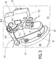
- FIGS. 1 to 3 a first embodiment of the adjusting device 10 according to the invention is shown.
- a protective element 12 is shown by the adjusting device 10 in its opening position IIb, in which a functional unit 15 is accessible from the outer region 10.1 of the adjusting device 10.
- the illustrated functional unit 15 is a camera 15.1, which permits image capture via a lens 15.2 and is arranged in the inner region 10.2 of the adjusting device 10.
- the image data acquired by the camera 15.1 can be displayed in a vehicle on a display or monitor.
- the adjusting device 10 may be arranged in particular in the rear region of a vehicle to z. B. to facilitate a reverse drive.
- the adjusting device 10 may itself be fastened to a carrier element 80, wherein the carrier element 80 may be a body part, a rear apron or another attachment of a vehicle.
- the carrier element 80 may be a body part, a rear apron or another attachment of a vehicle.
- an opening 81 may be provided in the carrier element 80.
- a bead 81 may be provided in the support member 80, whereby the adjusting device 10, in particular with its protective element 12 is arranged approximately flush with the surface of the support member 80.
- the protective element 12 remains in its open position IIb, an additional positive and / or frictional connection in the region of the end positions is provided which acts directly or indirectly on the protective element 12.
- the functional unit 15, in particular the camera 15.1 remains in its desired position even on a bumpy road, since it is firmly arranged on an inner side 12.2 of the protective element 12 and follows the movement of the protective element 12.
- the images taken by the camera 15.1 can be forwarded via an electrical line 22 to the vehicle interior.
- An electrical power supply of the adjusting device 10 can take place via the lateral plug 23 on a drive unit 13, in which the drive 14, in particular as an electric motor is arranged.
- the corresponding drive power of the drive 14 is transmitted via the drive mechanism 18 to at least the protective element 12.
- the functional unit 15 may be arranged on a carriage or lever of the drive mechanism 18 and is thus not firmly connected to the protective element 12.
- the protective element 12 of the adjusting device 10 is shown in its closed position IIa and mounting position Ia.
- the mode of operation of the adjusting device 10 will be explained below.
- the drive power from the drive 14 is transmitted via an indicated worm gear 18.5 to an intermediate shaft 18.3 as a rotary motion.
- a sliding block 18.4 is arranged eccentrically, which cooperates with a closed guide 18.12 of a lever-shaped connecting element 18.1 of the drive mechanism 18.
- a rotation of the intermediate shaft 18.3 counterclockwise pushes the lever-shaped connecting element 18.1 down or ensures a clockwise rotation about an axis of rotation 18.21, which provides a fixed pivot point of the connecting element 18.1.
- the connecting element 18.1 is rotatably connected to the further axis of rotation 18:21 of the lever 18.2, for which purpose a corresponding square is provided as a rotationally fixed connection 18.11.
- a corresponding square is provided as a rotationally fixed connection 18.11
- the maximum opening position IIb is limited by a stop between the lever 18.2 and the adjusting device 10.
- the lever-shaped connecting element 18.1 can not turn further clockwise or depressed, otherwise there would be a significant tension of the entire drive mechanism 18.
- the drive 14 can be switched off in the end positions IIa, IIb, respectively, since there is a self-locking gear in the drive mechanism 18, which is realized solely by the worm gear 18.5. Consequently, only one rotation of the drive shaft of the drive 14 can lead to an adjustment of the protective element 12 and not vice versa.
- the protective element 12 is secured by an additional positive and / or frictional connection in the region of the end position IIa and IIb, which from the FIGS. 4a to 6 is still clear.
- FIG. 3 is a three-dimensional view of the adjusting device 10 in a mounting position Ib shown.
- the adjustment device 10 according to the invention has the technical advantage that it is particularly easy to assemble or fasten even with small openings on a support member 80 in the assembled state.
- the Corresponding assembly can take place exclusively on one side of an outer region 10.1 (see the outer side 12.1 of the protective element 12) of the carrier element 80.
- the drive unit 13 is pivoted to the active unit 11, wherein initially an upper holding means 13.1 behind a likewise upper counter holding means 11.1 of the active unit 11 moves or tilts and then lock the lower holding means 13.1 with the corresponding lower counter holding means 13.1 of the active unit 13.
- a buffer 21 is arranged on the housing of the active unit 11 such that this buffer 21 comes to rest between the housings of the active unit 11 and the drive unit 13. Through this buffer 21 it is achieved that the two units 11, 13 are arranged without play and thus rattle-free in the mounting position Ia to each other.
- the adjusting device 10 of the invention via the active unit 11 and designated fasteners 19 attached to the support member 80, but this attachment can only be made when first the adjustment device 10 has been transferred from its mounting position Ib in the mounting position Ia.
- the drive unit 13 the entire mechanical drive power for the adjusting device 10 is generated.
- the functional unit 15 can also be moved synchronously with the protective element 12 or asynchronously via the drive mechanism 18.
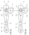
- FIG. 4a is the operation of an additional frictional connection for fixing the protective element in the region of the end positions IIa, IIb shown schematically.
- the lever-shaped connecting element 18.1 is in an approximately horizontal position (s. FIG. 2 , Closing position IIa of the protective element 12), so that the protective element 12 is pressed against a seal 11.2 at one edge of the adjusting device 10 in order to protect the adjusting device 10 reliably against external environmental influences.
- the lever-shaped connecting element 18.1 is in the FIG. 4a at the top dead center purple of the sliding block 18.4 slightly bent, which is indicated by the bending line 51, the above the normal longitudinal axis of the connecting element 18.1 (see also horizontal) is located. So that this deformation or deflection of the connecting element 18.1 can be carried out without damage to the drive mechanism 18, an elastic region 20 is provided on the connecting element 18.1, which is provided in the form of a constriction or cross-sectional tapering 20.1.
- the elastic region 20 can also be realized by a rubber-elastic buffer element, a spring element or the like.
- the protective element 12 is pressed with maximum force against the seal 11.2.
- the adjustment device 10 can be dispensed with an additional latching means 16 and counter-locking means 17, since only the deformable portion 20 assumes the function of generating an additional force in the region of the end position IIa and IIb for the protective element 12.
- the sliding block 18.4 is in its lower position IIIb.
- the sliding block has 18.4 rotated by the intermediate shaft 18.3 by about 170 ° from its upper position purple and is in an approximately 7 o'clock position.
- a deformation of the connecting element takes place 18.1 - as in Fig. 2 and 4a -, But now the connecting element 18.1 is pressed down, so that the corresponding bending line 51 is below the normal longitudinal axis 50 of the connecting element 18.1.
- FIGS. 5a to 5d an additional locking means 16 and a corresponding counter-locking means 17 is used, which cooperates with the drive mechanism 18 in order to produce the additional positive and / or frictional connection for securing the closing element 12 in its end position IIa, IIb.
- the comparable connecting element 18.1 comes from the FIGS. 4a and 4b for use. This can also be bent in the region of the end position Ia, Ib in order to securely hold or fix the protective element 12 in its end position IIa, IIb.
- the deformation of the lever-shaped connecting element 18.1 is only optional to the additional locking 16 and counter-locking means 17 conceivable.
- FIG. 18.1 is only optional to the additional locking 16 and counter-locking means 17 conceivable.
- a locking means 16 which consists of a spherical projection 16.1 and a spring 16.2.
- a spring 16.2 of the spherical projection 16.1 is pressed against the circular edge of the intermediate shaft 18.3.
- a spherical recess 17.1 is provided as a counter-locking means 17.
- the intermediate shaft 18.3 in its upper position purple but the locking means 16 is not yet forms an additional positive and / or frictional connection with the counter-locking means 17.
- FIGS. 5c and 5d Alternative embodiments of the locking means 16 and counter-locking means 17 are shown.
- FIG. 5c is a kinematic reversal to the locking means 16 and counter-locking means 17 from the FIGS. 5a and 5b shown.
- the locking means 16 is shown as a recess which is loaded by a spring 16.2.
- the counter-locking means 17 on the intermediate shaft 18.3 can be seen as a spherical projection which interacts mechanically with the recess in the latching means 16.
- FIG. 5d a further variant of the locking means 16 and the counter-locking means 17 is shown.
- the counter-locking means 17 substantially corresponds to the recess 17.1 from the FIGS. 5a and 5b ,
- the locking means 16 itself is configured in one piece, so that the projection 16.1 is represented by the spring 16.2 itself.
- This may be z. B. to a leaf spring or leg spring or the like, the form-fitting and / or non-positively cooperates with its projection 16.1 with the recess 17.1 of the counter-locking means.
- FIG. 6 schematically a side view of essential elements of the adjusting device 10 is shown to show a major part of the drive mechanism 18. This also makes it clear once again how the rotary motion of the intermediate shaft 18.3 is transmitted via the sliding block 18.4 to the connecting element 18.1, whereby the lever 18.2 is then adjusted with the protective element 12.
- the locking element 16 acts with a rounded projection 16.1 on the end of the connecting element 18.1, which is directed to the intermediate shaft 18.3.
- a recess 17.1 is provided, which cooperates as a counter-locking means 17 with the locking means 16 positively and non-positively.
- the locking means 16 also has a spring 16.2 for this purpose.
- an actuating element 15.1 indicated which serves to z. As a lock for a tailgate mechanically or electromechanically to operate to open them.
Description
Die Erfindung betrifft eine Verstellvorrichtung für Fahrzeuge oder dergleichen gemäß dem Oberbegriff von Anspruch 1 mit zumindest einem Schutzelement, insbesondere in Form eines Deckels, um einen Innenbereich hinter dem Schutzelement verschließbar auszugestalten. Ferner ist die Verstellvorrichtung mit einer Funktionseinheit, die hinter dem Schutzelement im Innenbereich angeordnet ist, ausgestattet und mit zumindest einem Antrieb, wodurch das Schutzelement zumindest zwischen zwei Endpositionen bewegbar ist, nämlich in eine Schließposition, in der das Schutzelement den Innenbereich verschließt, und in eine Öffnungsposition, in der das Schutzelement den Innenbereich öffnet.The invention relates to an adjusting device for vehicles or the like according to the preamble of claim 1 with at least one protective element, in particular in the form of a lid, to make an interior area behind the protective element lockable. Furthermore, the adjusting device with a functional unit, which is arranged behind the protective element in the interior, equipped and with at least one drive, whereby the protective element is movable at least between two end positions, namely in a closed position in which the protective element closes the inner region, and in a Opening position in which the protective element opens the interior.
Des Weiteren ist die vorliegende Erfindung auch auf ein Verfahren zum Betrieb einer Verstellvorrichtung für Fahrzeuge oder dergleichen gerichtet, die zumindest ein Schutzelement aufweist, insbesondere in Form eines Deckels, um einen Aus der
Aus dem Stand der Technik ist die Druckschrift
Aus der
Aufgabe der vorliegenden Erfindung ist es somit eine robuste Verstellvorrichtung zu schaffen, die auch äußeren mechanischen Einwirkungen Stand hält. Ferner ist es Aufgabe der vorliegenden Erfindung, ein entsprechendes Verfahren zum sicheren Betrieb einer derartigen Verstellvorrichtung bereitzustellen, das auch äußeren mechanischen Einwirkungen Stand hält.Object of the present invention is thus to provide a robust adjustment, which also withstands external mechanical effects. A further object of the present invention is to provide a corresponding method for the secure operation of such an adjusting device, which also withstands external mechanical influences.
Die vorliegende Aufgabe wird durch eine Verstellvorrichtung für Fahrzeuge, insbesondere Kraftfahrzeuge oder dergleichen mit den Merkmalen gemäß dem Patentanspruch 1, insbesondere aus dem kennzeichnenden Teil, gelöst.The present object is achieved by an adjusting device for vehicles, especially motor vehicles or the like having the features according to claim 1, in particular from the characterizing part.
Erfindungsgemäß ist es bei der Verstellvorrichtung vorgesehen, dass das Schutzelement im Bereich der Endpositionen zusätzlich form- und/oder kraftschlüssig fixiert ist, um somit das Schutzelement auch bei störenden mechanischen Einwirkungen in diesen Endpositionen zu halten. Dabei wird das Schutzelement selbstständig, d. h. ohne eine Antriebsleistung vom Antrieb, sicher gehalten. Damit ist sichergestellt, dass das Schutzelement in seiner Schließposition sicher mit einer Dichtung zusammenwirkt, um Spritzwasser, Schmutz und dergleichen aus dem Innenbereich der Verstellvorrichtung fernzuhalten. Auch ist dadurch ein guter Diebstahlschutz erzielbar. In der Öffnungsposition verharrt das Schutzelement ebenfalls sicher durch die zusätzliche Fixierung des Form- und/oder Kraftschlusses, sodass z. B. eine Kamera als Funktionseinheit, die hinter dem Schutzelement angeordnet sein kann, ihren vorgegebenen Bilderfassungsbereich zuverlässig aufnehmen kann. Dieses ist selbst bei starken mechanischen Erschütterungen möglich, wenn z. B. das Fahrzeug über eine Schotterpiste oder grobe Bodenunebenheiten fährt. Folglich ist sichergestellt, dass sich das Schutzelement nicht bei diesen mechanischen Erschütterungen langsam von der Öffnungsposition in die Schließposition bewegt und umgekehrt.According to the invention it is provided in the adjustment that the protective element is additionally fixed positively and / or non-positively in the region of the end positions, so as to keep the protective element even with disturbing mechanical effects in these end positions. In this case, the protective element automatically, ie without a drive power from the drive, held securely. This ensures that the protective element in its closed position securely cooperates with a seal to splash water, dirt and the like to keep out of the interior of the adjustment. Also, this is a good theft protection achievable. In the open position, the protective element also remains secure due to the additional fixation of the positive and / or frictional connection, so that z. B. a camera as a functional unit that can be located behind the protection element, can reliably record their predetermined image capture area. This is possible even with strong mechanical shocks when z. B. the vehicle drives over a gravel road or rough bumps. Consequently, it is ensured that the protective element does not move slowly from the open position to the closed position during these mechanical vibrations and vice versa.
Die Erfindung ist in diversen Ausgestaltungen durch die abhängigen Unteransprüche und die nachfolgende Beschreibung offenbart. Dabei gelten Merkmale und Details, die im Zusammenhang mit der erfindungsgemäßen Vorrichtung offenbart werden auch im Zusammenhang mit dem erfindungsgemäßen Verfahren und umgekehrt, so dass bzgl. der Offenbarung zu den einzelnen Erfindungsaspekten stets wechselseitig Bezug genommen wird.The invention is disclosed in various aspects by the dependent subclaims and the following description. In this case, features and details which are disclosed in connection with the device according to the invention also apply in connection with the method according to the invention and vice versa, so that with respect to the disclosure of the individual aspects of the invention always reciprocal reference is made.
Bei der erfindungsgemäßen Verstellvorrichtung kann es vorgesehen sein, dass die Funktionseinheit fest an einer Innenseite von dem Schutzelement befestigt ist und einer Bewegung des Schutzelementes folgt. Somit wird auch die Funktionseinheit weggeschwenkt, wenn auch das Schutzelement geschwenkt wird. Sofern das Schutzelement in der Schließposition ist, ist somit auch die Funktionseinheit unzugänglich in der Verstellvorrichtung angeordnet und gegen äußere Umwelteinflüsse geschützt. Ebenfalls ist es denkbar, dass die Funktionseinheit im Innenbereich unabhängig vom Schutzelement fest oder bewegbar angeordnet ist und trotzdem durch das Schutzelement in der Schließposition unzugänglich von der Außenseite geschützt ist. Je nach Anwendungsbereich kann somit die Funktionseinheit an bzw. in der Verstellvorrichtung angeordnet sein. Hierbei ist es insbesondere von Interesse, eine gute Zugänglichkeit der Funktionseinheit in der Öffnungsposition des Schutzelementes zu erreichen. Die Funktionseinheit kann dabei selbst eine Kameraeinheit, einen Schließzylinder und/oder ein Betätigungselement aufweisen. Bei einer Kameraeinheit als Funktionseinheit ist sicherzustellen, dass ein optimaler Blickwinkel für das Objektiv der Kameraeinheit gewährleistet ist, wenn das Schutzelement in der Öffnungsposition steht. Zu diesem Zweck kann die Kameraeinheit an einem beweglichen Schlitten oder einer Bewegungsmechanik angeordnet sein, um diese relativ zum Schutzelement und der übrigen Verstellvorrichtung zu bewegen. Selbstverständlich kann auch ein Schließzylinder und/oder ein Betätigungselement beweglich zur Verstellvorrichtung angeordnet sein. Hierdurch lassen sich technisch sehr komfortable Verstellvorrichtungen für Fahrzeuge erreichen, die besonders einfach zu bedienen sind. Sofern die Funktionseinheit auch ein Betätigungselement oder einen Schließzylinder aufweist, kann das Schutzelement über einen Näherungssensor oder einen Berührungssensor angesteuert werden, um das Schutzelement in seinen Endpositionen zu bewegen. Selbstverständlich kann auch das Schutzelement automatisch angesteuert werden, wenn die Funktionseinheit durch eine Kameraeinheit realisiert wird. Hierbei kann z. B. durch das Einlegen eines Rückwärtsganges eine automatische Ansteuerung des Schutzelementes in die Öffnungsposition erfolgen. Eine Bilddarstellung der erfassten Bilder von der Kameraeinheit kann auf einem Monitor oder Display im Fahrzeuginneren angezeigt werden. Das Schutzelement selbst kann an seiner Außenseite in Fahrzeugfarbe lackiert sein oder eine verchromte Oberfläche aufweisen. Auch ist es denkbar, dass an der Außenseite des Schutzelementes ein Herstelleremblem angeordnet sein kann.In the adjusting device according to the invention, it may be provided that the functional unit is fixedly secured to an inner side of the protective element and follows a movement of the protective element. Thus, the functional unit is pivoted away, even if the protective element is pivoted. If the protective element is in the closed position, the functional unit is thus also arranged inaccessible in the adjusting device and protected against external environmental influences. It is also conceivable that the functional unit in the interior is arranged fixed or movable independently of the protective element and is nevertheless protected by the protective element in the closed position inaccessible from the outside. Depending on the field of application, the functional unit can thus be arranged on or in the adjusting device. In this case, it is of particular interest to achieve good accessibility of the functional unit in the opening position of the protective element. The functional unit may itself have a camera unit, a lock cylinder and / or an actuating element. In the case of a camera unit as a functional unit, it must be ensured that an optimum viewing angle for the lens of the camera unit is ensured when the protective element is in the open position. For this purpose, the camera unit on a movable Carriage or a movement mechanism can be arranged to move them relative to the protective element and the rest of the adjusting device. Of course, a lock cylinder and / or an actuating element can be arranged to be movable to the adjusting device. As a result, technically very comfortable adjustment devices for vehicles can be achieved which are particularly easy to operate. If the functional unit also has an actuating element or a lock cylinder, the protective element can be actuated via a proximity sensor or a touch sensor in order to move the protective element in its end positions. Of course, the protective element can be controlled automatically when the functional unit is realized by a camera unit. This z. B. by inserting a reverse gear automatic control of the protective element in the open position. An image representation of the captured images from the camera unit can be displayed on a monitor or display in the vehicle interior. The protective element itself may be painted on its outside in vehicle color or have a chrome-plated surface. It is also conceivable that a manufacturer's emblem can be arranged on the outside of the protective element.
Ebenfalls wird durch die zusätzliche Fixierung des Schutzelementes im Bereich der Endpositionen durch den zusätzlichen vorgesehenen Form- oder Kraftschluss der Einbruch- und Diebstahlschutz deutlich verbessert, da sich das Schutzelement aus der Schließposition nur durch massive Gewalteinwirkung verstellen lässt, wobei gleichzeitig eine Zerstörung der Verstellvorrichtung die Folge ist. Normale Aufbruchsversuche mit der Hand oder einem einfachen Schraubendreher führen hingegen nicht zu einer ungewollten Öffnung des Schutzelementes.Also, the burglary and theft protection is significantly improved by the additional fixation of the protective element in the area of the end positions by the additional provided form or adhesion, since the protective element from the closed position can only be adjusted by massive violence, at the same time destruction of the adjustment result is. Normal attempts to break open by hand or a simple screwdriver, however, do not lead to an unwanted opening of the protective element.
Erfindungsgemäß kann es ebenfalls vorgesehen sein, dass der zusätzliche Form- und/oder Kraftschluss im Bereich der Endposition durch ein (zusätzliches) Rastmittel erzeugbar ist. Dieses Rastmittel kann einen federbelasteten Vorsprung aufweisen, der mit einer Ausnehmung als Gegenrastmittel form- und/oder kraftschlüssig zusammenwirkt. Das Rastmittel kann dabei direkt mit dem Schutzelement, eine Antriebsmechanik und/oder dem Antrieb mechanisch zusammenwirken. Das entsprechende Gegenrastmittel ist dann an einem Gehäuse der Verstellvorrichtung oder an einem anderen Element als dem Rastmittel angeordnet, damit Rastmittel und Gegenrastmittel form- und/oder kraftschlüssig zusammenwirken können. Das Rastmittel kann aus einer federbelasteten Kugel, einer Blattfeder mit Vorsprung, oder einem nachgiebigen Vorsprung bestehen. Selbstverständlich ist auch eine kinematische Umkehr zwischen dem bereits erwähnten Rastmittel und dem Gegenrastmittel denkbar, um den zusätzlichen Form- und/oder Kraftschluss im Bereich der Endpositionen des Schutzelementes zu erzeugen.According to the invention, it may also be provided that the additional positive and / or non-positive connection in the region of the end position can be generated by an (additional) latching means. This locking means may comprise a spring-loaded projection which cooperates with a recess as a counter-locking means form and / or non-positively. The locking means may interact directly with the protective element, a drive mechanism and / or the drive mechanically. The corresponding counter-locking means is then arranged on a housing of the adjusting device or on another element than the locking means, so that locking means and counter-locking means positive and / or non-positive can interact. The locking means may consist of a spring-loaded ball, a leaf spring with a projection, or a resilient projection. Of course, a kinematic reversal between the already mentioned locking means and the counter-locking means is conceivable to produce the additional positive and / or positive connection in the region of the end positions of the protective element.
Bei einer besonderen Variante der vorliegenden erfindungsgemäßen Verstellvorrichtung kann es vorgesehen sein, dass eine Antriebsmechanik zwischen dem Antrieb und dem Schutzelement angeordnet ist und der zusätzliche Kraftschluss durch einen elastisch verformbaren Bereich, insbesondere von der Antriebsmechanik, dem Antrieb und/oder dem Schutzelement, erzeugbar ist. Somit kann auf das zusätzliche Rastmittel und Gegenrastmittel als gesondertes Element verzichtet werden und trotzdem wird das Schutzelement im Bereich der Endposition durch den zusätzlichen Form- und/oder Kraftschluss im Bereich der Endpositionen belastet bzw. fixiert. Durch den elastisch verformbaren Bereich ist es möglich, eine gewollte Verformung der Antriebsmechanik im Bereich der Endpositionen zu erzeugen, die zu dem gewünschten zusätzlichen Form- und/oder Kraftschluss im Bereich der Endposition des Schutzelementes führt. Hierzu kann insbesondere ein Verbindungselement der Antriebsmechanik vorgesehen sein, welches insbesondere über einen elastischen Bereich verfügt. Dieses Verbindungselement kann z. B. hebelartig ausgestaltet sein, wobei der elastische Bereich z. B. als Einschnürung, Querschnittsverjüngung, Gummi- oder Federelement oder dergleichen ausgestaltet sein kann. Durch die bewusste elastische Verformung des Verbindungselementes kann dann der zusätzliche Kraftschluss im Bereich der Endpositionen des Schutzelementes erzeugt werden. Der elastische Bereich kann aber auch im Bereich einer drehfesten Verbindung zwischen zwei Elementen der Antriebsmechanik vorgesehen sein, wodurch die gewünschte Verformung an dieser Stelle erreichbar ist. Somit ist der elastische Bereich nicht auf ein hebelförmiges Verbindungselement in der Antriebsmechanik beschränkt, sondern der elastische Bereich kann komplett zwischen der Antriebsseite vom Antrieb und der Abtriebsseite an das Schutzelement vorgesehen sein.In a particular variant of the present adjusting device according to the invention, it can be provided that a drive mechanism is arranged between the drive and the protective element and the additional adhesion can be generated by an elastically deformable region, in particular by the drive mechanism, the drive and / or the protective element. Thus, it is possible to dispense with the additional latching means and counter-latching means as a separate element and nevertheless the protective element is loaded or fixed in the area of the end position by the additional positive and / or non-positive connection in the area of the end positions. Due to the elastically deformable region, it is possible to produce a desired deformation of the drive mechanism in the region of the end positions, which leads to the desired additional positive and / or positive connection in the region of the end position of the protective element. For this purpose, in particular, a connecting element of the drive mechanism can be provided, which in particular has an elastic region. This connecting element can, for. B. be configured like a lever, wherein the elastic region z. B. as constriction, cross-sectional taper, rubber or spring element or the like can be configured. By the deliberate elastic deformation of the connecting element of the additional adhesion can then be generated in the region of the end positions of the protective element. However, the elastic region can also be provided in the region of a rotationally fixed connection between two elements of the drive mechanism, whereby the desired deformation can be achieved at this point. Thus, the elastic portion is not limited to a lever-shaped connecting member in the drive mechanism, but the elastic portion may be completely provided between the drive side of the drive and the output side to the protective element.
Ebenfalls kann es erfindungsgemäß vorgesehen sein, dass der Antrieb und/oder die Antriebsmechanik (z. B. als Schneckengetriebe, Vielgelenkgetriebe) selbsthemmend ausgestaltet ist, sodass eine Verstellung des Schutzelementes ausschließlich über den Antrieb erfolgt. Aufgrund der Selbsthemmung ist es nicht möglich, von der Abtriebsseite, d. h. durch das Schutzelement, eine Bewegung der Antriebsmechanik oder des Antriebes zu erzeugen. Damit ist das Schutzelement grundsätzlich in jeder Position gehalten, weil die Selbsthemmung eine Verstellung des Schutzelementes durch eine mechanische Einwirkung direkt auf das Schutzelement unmöglich macht. Somit kann das Schutzelement nur durch den Antrieb zwischen den Endpositionen verfahren werden. Zusätzlich wird im Bereich der Endposition der gewünschte Form- und/oder Kraftschluss erzeugt, um störenden Einflüsse von Antriebsseite zu unterdrücken.It may also be provided according to the invention that the drive and / or the drive mechanism (eg as worm gear, multi-link gearbox) is designed to be self-locking, so that an adjustment of the protective element exclusively via the Drive takes place. Due to the self-locking, it is not possible to generate from the output side, ie by the protective element, a movement of the drive mechanism or the drive. Thus, the protective element is basically held in any position, because the self-locking makes an adjustment of the protective element by a mechanical action directly on the protective element impossible. Thus, the protective element can be moved only by the drive between the end positions. In addition, the desired positive and / or positive connection is generated in the region of the end position in order to suppress disturbing influences from the drive side.
Bei der erfindungsgemäßen Verstellvorrichtung ist es ebenfalls denkbar, dass zumindest der Antrieb für das Schutzelement in einer Antriebseinheit angeordnet ist und das Schutzelement an eine Aktiveinheit vorgesehen ist, und das die Antriebseinheit im zusammengebauten Zustand der Verstellvorrichtung bewegbar zur Aktiveinheit ausgestaltet ist, wobei insbesondere die Antriebseinheit in einer Befestigungslage fest mit der Aktiveinheit verbunden ist. Folglich ist die Antriebseinheit der Verstellvorrichtung nicht starr zur Aktiveinheit ausgestaltet, sondern kann vielmehr in einer Montagelage relativ zur Aktiveinheit bewegt werden. Durch diese zusätzliche Bewegungsmöglichkeit ist eine einfache Montage der erfindungsgemäßen Verstellvorrichtung an einem Trägerelement möglich. Hierbei kann die Verstellvorrichtung auch durch eine kleine Öffnung in dem Trägerelement durchgeführt werden, um anschließend an dem Trägerelement befestigt zu werden. Zu diesem Zweck kann die Antriebseinheit mit der Aktiveinheit in der Montagelage in eine lang gestreckte Lage verstellt werden, um somit auch eine einseitige Durchführungen der Verstellvorrichtung durch die Öffnung am Trägerelement deutlich zu erleichtern. Folglich kann auf eine beidseitige Montage der Verstellvorrichtung an dem Trägerelement verzichtet werden. Sobald die Verstellvorrichtung mit der Antriebseinheit und teilweise der Aktiveinheit durch die Öffnung des Trägerelementes hindurch geschoben worden ist, lässt sich die Antriebseinheit an die Aktiveinheit heranschwenken, um die Befestigungslage einzunehmen. In dieser Befestigungslage ist die Antriebseinheit mit der Aktiveinheit über Haltemittel und Gegenhaltmittel form- und/oder kraftschlüssig verbunden.In the adjusting device according to the invention, it is also conceivable that at least the drive for the protective element is arranged in a drive unit and the protective element is provided to an active unit, and the drive unit is configured in the assembled state of the adjusting movable to the active unit, wherein in particular the drive unit in a fastening position is firmly connected to the active unit. Consequently, the drive unit of the adjusting device is not designed rigidly to the active unit, but rather can be moved in an assembly position relative to the active unit. By this additional movement possibility a simple mounting of the adjusting device according to the invention on a support element is possible. In this case, the adjusting device can also be carried out through a small opening in the carrier element in order subsequently to be fastened to the carrier element. For this purpose, the drive unit can be adjusted with the active unit in the mounting position in an elongated position, so as to facilitate a one-sided implementations of the adjusting device through the opening on the support element significantly. Consequently, can be dispensed with a two-sided mounting of the adjusting device on the support element. As soon as the adjusting device with the drive unit and partly the active unit has been pushed through the opening of the carrier element, the drive unit can be pivoted to the active unit in order to assume the fastening position. In this mounting position, the drive unit with the active unit via retaining means and counter-holding means is positively and / or non-positively connected.
Ferner kann es im Rahmen der Erfindung vorgesehen sein, dass die Antriebseinheit mechanisch über zumindest einen Teil der Antriebsmechanik, insbesondere dem Verbindungselement, mit der Aktiveinheit verbunden ist, um die Antriebsleistung des Antriebes auf das Schutzelement zu übertragen. Die Antriebsmechanik kann hierbei als einfaches Zahnradgetriebe, Vielgelenkgetriebe oder dergleichen ausgestaltet sein. Das zuvor erwähnte Verbindungselement kann als ein Dreh- bzw. Schwenkhebel realisiert werden, wobei das Verbindungselement an dem einen Ende mit der Antriebseinheit und an dem anderen Ende mit der Aktiveinheit verbunden ist. Die Verbindung zwischen der Antriebseinheit und dem Verbindungselement kann als eine geschlossene Führung, insbesondere in Form eines Langloches und eines Kulissensteins ausgestaltet sein. Die Verbindung zwischen dem Verbindungselement und der Aktiveinheit kann hingegen als eine drehfeste Verbindung durch einen Vierkant-, Vielzahn- oder eine Klemmverbindung realisiert werden. Ebenfalls ist es denkbar, dass die Antriebsleistung über zwei Verbindungselemente auf die Antriebseinheit übertragen wird. Selbstverständlich kann die Antriebseinheit auch zwei Antriebe aufweisen, um das Schutzelement unabhängig von der Funktionseinheit relativ zur Verstellvorrichtung zu bewegen. Sofern nur ein Antrieb zum Einsatz kommt, kann die Antriebsleistung über die Antriebsmechanik getrennt für das Schutzelement und die Verstellung der Funktionseinheit bereit gestellt werden.Furthermore, it can be provided in the context of the invention that the drive unit is mechanically connected via at least part of the drive mechanism, in particular the connecting element, with the active unit to the drive power of Drive to transfer to the protective element. The drive mechanism can be designed here as a simple gear transmission, multi-link transmission or the like. The aforementioned connecting element can be realized as a rotary lever, wherein the connecting element is connected at one end to the drive unit and at the other end to the active unit. The connection between the drive unit and the connecting element can be designed as a closed guide, in particular in the form of a slot and a sliding block. The connection between the connecting element and the active unit, however, can be realized as a rotationally fixed connection by a square, multi-tooth or a clamping connection. It is also conceivable that the drive power is transmitted to the drive unit via two connecting elements. Of course, the drive unit can also have two drives in order to move the protective element independently of the functional unit relative to the adjusting device. If only one drive is used, the drive power can be provided separately via the drive mechanism for the protective element and the adjustment of the functional unit.
Die zuvor genannte Aufgabe der Erfindung kann auch durch ein Verfahren zum Betrieb einer Verstellvorrichtung für Fahrzeuge oder dergleichen mit den technischen Merkmalen aus dem unabhängigen Anspruch 14, insbesondere aus dem kennzeichnenden Teil, gelöst werden. Dabei ist es erfindungsgemäß vorgesehen, dass das Schutzelement im Bereich der Endposition zusätzlich form- und/oder kraftschlüssig fixiert wird, um das Schutzelement auch bei störenden mechanischen Einwirkungen in diesen Endpositionen sicher zu halten.The aforementioned object of the invention can also be achieved by a method for operating an adjusting device for vehicles or the like with the technical features of the
Das erfindungsgemäße Verfahren zum Betrieb der Verstellvorrichtung kann mit der erfindungsgemäßen Verstellvorrichtung gemäß der Ansprüche 1 bis 13 durchgeführt werden. Ebenfalls dient die erfindungsgemäße Verstellvorrichtung auch zur Durchführung des erfindungsgemäßen Verfahrens.The inventive method for operating the adjusting device can be carried out with the adjusting device according to the invention according to claims 1 to 13. Likewise, the adjusting device according to the invention also serves to carry out the method according to the invention.
Weitere Vorteile, Merkmale und Einzelheiten der Erfindung ergeben sich aus der nachfolgenden Beschreibung, in der unter Bezugnahme auf die Zeichnungen die Erfindung in mehreren Ausführungsbeispielen beschrieben ist. Dabei können die in den Ansprüchen und in der Beschreibung erwähnten Merkmale einzeln für sich oder in beliebiger Kombination erfindungswesentlich sein. Es zeigen:
- Fig. 1
- eine Seitenansicht der erfindungsgemäßen Verstellvorrichtung in einer Öffnungsposition,
- Fig. 2
- die Verstellvorrichtung aus
Figur 1 in einer Schließposition, bei der eine Funktionseinheit unzugänglich ist, - Fig. 3
- eine dreidimensionale Ansicht der Verstellvorrichtung aus
Figur 1 und 2 , in einer Montagelage, - Fig. 4a
- eine schematische Ansicht zur Funktionsweise einer Antriebsmechanik der Verstellvorrichtung mit einem elastischen Bereich, wobei eine gewünschte Verformung vorliegt,
- Fig. 4b
- eine vergleichbare Ansicht der Antriebsmechanik aus
Figur 4a jedoch ohne eine Verformung, - Fig. 5a
- eine schematische Ansicht zur Antriebsmechanik (vergleichbar zu den
Figuren 4a, b ) mit einem zusätzlichen Rastmittel, - Fig. 5b
- eine schematische Ansicht der Antriebsmechanik aus
Figur 5a mit einem eingerasteten Rastmittel, bei der ein zusätzlicher Form- und Kraftschluss vorliegt, - Fig. 5c
- eine schematische Ansicht zu einer Variante des Rastmittels aus den
Figuren 5a und b in Zusammenwirkung mit dem Gegenrastmittel, - Fig. 5d
- eine schematische Ansicht eines weiteren Rastmittels und Gegenrastmittels im Vergleich zu den
Figuren 5a, b und c sowie - Fig. 6
- eine schematische Seitenansicht auf die wesentlichen Antriebselemente der erfindungsgemäßen Verstellvorrichtung mit einer weiteren Variante für das zusätzliche Rast- und Gegenrastmittel.
- Fig. 1
- a side view of the adjusting device according to the invention in an open position,
- Fig. 2
- the adjustment from
FIG. 1 in a closed position where a functional unit is inaccessible, - Fig. 3
- a three-dimensional view of the adjustment of
FIGS. 1 and 2 in a mounting position, - Fig. 4a
- a schematic view of the operation of a drive mechanism of the adjusting device with an elastic region, wherein a desired deformation is present,
- Fig. 4b
- a comparable view of the drive mechanism
FIG. 4a but without deformation, - Fig. 5a
- a schematic view of the drive mechanism (comparable to the
FIGS. 4a, b ) with an additional locking means, - Fig. 5b
- a schematic view of the drive mechanism
FIG. 5a with a latched latching means in which an additional positive and positive connection is present, - Fig. 5c
- a schematic view of a variant of the locking means of the
FIGS. 5a and b in cooperation with the counter-latching means, - Fig. 5d
- a schematic view of another locking means and counter-locking means in comparison to the
FIGS. 5a, b and c such as - Fig. 6
- a schematic side view of the main drive elements of the adjusting device according to the invention with a further variant of the additional locking and counter-locking means.
In den
Damit nun das Schutzelement 12 in seiner Öffnungsposition IIb verharrt, ist ein zusätzlicher Form- und/oder Kraftschluss im Bereich der Endpositionen vorgesehen, der direkt oder indirekt auf das Schutzelement 12 wirkt. Somit kann sichergestellt werden, dass auch bei einer holprigen Wegstrecke die Funktionseinheit 15, insbesondere die Kamera 15.1, in ihrer gewünschten Position verbleibt, da es fest an einer Innenseite 12.2 von dem Schutzelement 12 angeordnet ist und der Bewegung des Schutzelementes 12 folgt. Die von der Kamera 15.1 aufgenommenen Bilder können über eine elektrische Leitung 22 an das Fahrzeuginnere weitergeleitet werden. Eine elektrische Energieversorgung der Verstellvorrichtung 10 kann über den seitlichen Stecker 23 an einer Antriebseinheit 13 erfolgen, in der auch der Antrieb 14, insbesondere als Elektromotor angeordnet ist. Die entsprechende Antriebsleistung des Antriebs 14 wird über die Antriebsmechanik 18 auf zumindest das Schutzelement 12 übertragen. Ebenfalls kann durch den Antrieb 14 auch die Funktionseinheit 15 unabhängig vom Schutzelement 12 relativ zur Verstellvorrichtung 10 bewegt werden. Hierfür kann die Funktionseinheit 15 an einem Schlitten oder Hebel der Antriebsmechanik 18 angeordnet sein und ist somit nicht fest mit dem Schutzelement 12 verbunden.So that now the
In der
In der
In der
Das hebelförmige Verbindungselement 18.1 ist in der
Aus der
In der
In den weiteren
In der
In den
In der
In der
- 1010
- Verstellvorrichtungadjustment
- 10.110.1
- Außenbereichoutdoors
- 10.210.2
- Innenbereichinterior
- 1111
- Aktiveinheitactive unit
- 11.111.1
- Haltemittel für 13Holding means for 13
- 11.211.2
- Dichtungpoetry
- 1212
- Schutzelementprotection element
- 12.112.1
- Außenseiteoutside
- 12.212.2
- Innenseiteinside
- 1313
- Antriebseinheitdrive unit
- 13.113.1
- Gegenhaltemittel für 11Counterpart funds for 11
- 1414
- Antriebdrive
- 1515
- Funktionseinheitfunctional unit
- 15.115.1
- Kamera, Schließzylinder oder BetätigungselementCamera, lock cylinder or actuator
- 15.215.2
- Objektivlens
- 1616
- Rastmittellatching means
- 16.116.1
- Vorsprunghead Start
- 16.216.2
- Federfeather
- 1717
- GegenrastmittelSecuring means
- 17.117.1
- Ausnehmungrecess
- 1818
- Antriebsmechanikdrive mechanism
- 18.118.1
- Verbindungselementconnecting member
- 18.1118:11
- drehfeste Verbindungnon-rotatable connection
- 18.1218:12
- Führungguide
- 18.218.2
- Hebel für 12Lever for 12
- 18.2118:21
- Drehachseaxis of rotation
- 18.318.3
- Zwischenwelleintermediate shaft
- 18.418.4
- Kulissensteinsliding block
- 18.518.5
- Schneckengetriebeworm gear
- 1919
- Befestigungsmittelfastener
- 2020
- elastischer Bereichelastic range
- 20.120.1
- Einschnürungconstriction
- 2121
- Pufferbuffer
- 2222
- Elektrische LeitungElectrical line
- 2323
- Steckerplug
- 5050
- Längsachselongitudinal axis
- 5151
- Biegelinieelastic line
- 5252
- Pfeil für DrehrichtungArrow for direction of rotation
- 8080
- Trägerelementsupport element
- 8181
- Umbördelungbeading
- IaIa
- Befestigungslagemounting location
- Ibib
- Montagelagemounting position
- IIaIIa
- Schließpositionclosed position
- IIbIIb
- Öffnungspositionopening position
- IIIaIIIa
- oberer Stellungupper position
- IIIbIIIb
- untere Stellunglower position
Claims (11)
- Adjustment device (10) for motor vehicles or the like, having at least one protective element (12), in particular in the form of a cover to enable a construction in which an interior region (10.2) is closable behind the protective element (12), and having a functional unit (15) which is arranged in the interior region (10.2) behind the protective element (12), and having at least one drive (14) by which the protective element (12) is movable between at least two end positions (IIa, IIb), namely into a closing position (IIa) in which the protective element (12) closes the interior region (10.2), and into an opening position (IIb) in which the protective element (12) opens the interior region (10.2), wherein the functional unit (15) contains a camera unit, a closing cylinder and/or an actuating element, wherein the protective element (12) is additionally fixed in form-fitting and/or force-fitting manner in the region of the end positions (IIa, IIb) in order to retain the protective element (12) in said end positions (IIa, IIb) even against the effects of disruptive mechanical influences, wherein the functional unit (15) is attached firmly to an inner side (12.2) of the protective element (12) and follows a movement of the protective element (12).
- Adjustment device (10) according to any one of the preceding claims, characterized in that the additional form-fitting and/or force-fitting closure in the region of the end positions (IIa, IIb) can be created with a detent means (16).
- Adjustment device (10) according to any one of the preceding claims, characterized in that the detent means (16) cooperates mechanically directly with the protective element (12), a drive mechanism (18) and/or the drive (14).
- Adjustment device (10) according to any one of the preceding claims, characterized in that the detent means (16) is designed as a resilient projection (16.1) and cooperates with a counter-detent means (17) in the form of a recess (17.1), thereby forming the additional form-fitting and/or force-fitting closure.
- Adjustment device (10) according to any one of the preceding claims, characterized in that a drive mechanism (18) is disposed between the drive (14) and the protective element (12), and the additional force-fitting closure can be created by an elastically deformable region (20) particularly of the drive mechanism (18), the drive (14) and/or the protective element (12).
- Adjustment device (10) according to any one of the preceding claims, characterized in that the drive (14) and/or the drive mechanism (18) is/are designed to be self-locking, so that an adjustment of the protective element (12) only takes place via the drive (14).
- Adjustment device (10) according to any one of the preceding claims, characterized in that the drive mechanism (18) includes a connecting element (18.1) which in particular has an elastic region (20).
- Adjustment device (10) according to any one of the preceding claims, characterized in that the additional force-fitting closure in the region of the end positions (IIa, IIb) of the protective element (12) must be overcome to enable a shift from one end position (IIa, IIb) to another end position (IIb, IIa).
- Adjustment device (10) according to any one of the preceding claims, characterized in that at least the drive (14) for the protective element (12) is disposed in a drive unit (13), and the protective element (12) is provided on an active unit (11), and that with the adjustment device (10) in the assembled state the drive unit (12) is configured to be movable towards the active unit (11), wherein in particular the drive unit (13) is connected firmly to the active unit (11) in a fastening position (Ia).
- Adjustment device (10) according to any one of the preceding claims, characterized in that the drive unit (13) is connected mechanically to the active unit (11) via at least a part of the drive mechanism (18), particularly the connecting element (18.1), for transmitting the driving power of the drive (14) to the protective element (12).
- Method for operating an adjustment device (10) for motor vehicles or the like according to any one of Claims 1 to 10, having at least one protective element (12), in particular in the form of a cover to enable a construction in which an interior region (10.2) is closable behind the protective element (12), and having a functional unit (15) which is arranged in the interior region (10.2) behind the protective element (12), and having at least one drive (14) by which the protective element (12) is movable between at least two end positions (IIa, IIb), namely into a closing position (IIa) in which the protective element (12) closes the interior region (10.2), and into an opening position (IIb) in which the protective element (12) opens the interior region (10.2), characterized in that the protective element (12) is additionally fixed in form-fitting and/or force-fitting manner in the region of the end positions (IIa, IIb) in order to retain the protective element (12) in said end positions (IIa, IIb) even against the effects of disruptive mechanical influences.
Applications Claiming Priority (2)
| Application Number | Priority Date | Filing Date | Title |
|---|---|---|---|
| DE102010060610A DE102010060610A1 (en) | 2010-11-16 | 2010-11-16 | Secure adjustment device |
| PCT/EP2011/070270 WO2012066046A1 (en) | 2010-11-16 | 2011-11-16 | Protected adjustment device |
Publications (2)
| Publication Number | Publication Date |
|---|---|
| EP2640606A1 EP2640606A1 (en) | 2013-09-25 |
| EP2640606B1 true EP2640606B1 (en) | 2018-01-10 |
Family
ID=45033950
Family Applications (1)
| Application Number | Title | Priority Date | Filing Date |
|---|---|---|---|
| EP11787823.1A Not-in-force EP2640606B1 (en) | 2010-11-16 | 2011-11-16 | Secured adjusting deivce |
Country Status (3)
| Country | Link |
|---|---|
| EP (1) | EP2640606B1 (en) |
| DE (1) | DE102010060610A1 (en) |
| WO (1) | WO2012066046A1 (en) |
Families Citing this family (1)
| Publication number | Priority date | Publication date | Assignee | Title |
|---|---|---|---|---|
| DE102015013315A1 (en) * | 2015-10-14 | 2017-04-20 | GM Global Technology Operations LLC (n. d. Ges. d. Staates Delaware) | Vehicle with camera unit |
Citations (1)
| Publication number | Priority date | Publication date | Assignee | Title |
|---|---|---|---|---|
| FR2493780A1 (en) * | 1980-11-13 | 1982-05-14 | Daimler Benz Ag | Motor vehicle boundary marker - has countersunk gauging rod mounted on vehicle body |
Family Cites Families (3)
| Publication number | Priority date | Publication date | Assignee | Title |
|---|---|---|---|---|
| FR2858280B1 (en) * | 2003-07-29 | 2008-12-26 | Valeo Systemes Dessuyage | REAR VISION DEVICE FOR MOTOR VEHICLE |
| DE10351363A1 (en) | 2003-11-04 | 2005-06-09 | Hella Kgaa Hueck & Co. | Camera arrangement for motor vehicles |
| DE102005052031B4 (en) * | 2005-10-31 | 2015-03-12 | Robert Bosch Gmbh | Foldable display device with cover, in particular for motor vehicles |
-
2010
- 2010-11-16 DE DE102010060610A patent/DE102010060610A1/en not_active Ceased
-
2011
- 2011-11-16 WO PCT/EP2011/070270 patent/WO2012066046A1/en active Application Filing
- 2011-11-16 EP EP11787823.1A patent/EP2640606B1/en not_active Not-in-force
Patent Citations (1)
| Publication number | Priority date | Publication date | Assignee | Title |
|---|---|---|---|---|
| FR2493780A1 (en) * | 1980-11-13 | 1982-05-14 | Daimler Benz Ag | Motor vehicle boundary marker - has countersunk gauging rod mounted on vehicle body |
Also Published As
| Publication number | Publication date |
|---|---|
| WO2012066046A1 (en) | 2012-05-24 |
| DE102010060610A1 (en) | 2012-05-16 |
| EP2640606A1 (en) | 2013-09-25 |
Similar Documents
| Publication | Publication Date | Title |
|---|---|---|
| EP2673168B1 (en) | Mounting assembly for simplified assembly on the vehicle | |
| EP2214931B1 (en) | Device having a camera unit | |
| EP2673169B1 (en) | Camera arrangement for a vehicle and method for installation | |
| EP2640608B1 (en) | Theft protection device for a camera unit | |
| EP2796324B1 (en) | Device with a camera unit | |
| EP2414197B1 (en) | Device with a camera unit for imaging the exterior of a vehicle | |
| DE102005052031B4 (en) | Foldable display device with cover, in particular for motor vehicles | |
| EP3037683B1 (en) | Auxiliary locking drive for a motor vehicle lock | |
| DE202011050412U1 (en) | Tank cover unit for a motor vehicle | |
| EP3526080B1 (en) | Camera module | |
| DE102010001196A9 (en) | Simplified device of a camera unit of a motor vehicle | |
| DE102012109611A1 (en) | Device for receiving a camera with four joints | |
| DE102014201886A1 (en) | Closure device for a filling or connection opening on a vehicle | |
| DE102015102726A1 (en) | Arrangement of a vehicle | |
| DE102012109610A1 (en) | Device for receiving a camera with a backdrop | |
| DE102012025626A1 (en) | Device for receiving a camera with four joints | |
| DE202009016813U1 (en) | Drive device for a display element of a motor vehicle | |
| EP2640606B1 (en) | Secured adjusting deivce | |
| EP3576987A1 (en) | Device for a motor vehicle | |
| DE102008059918A1 (en) | mounting module | |
| EP1362733B1 (en) | Tank door unit | |
| DE10116739B4 (en) | Motor vehicle locking device with shaft as a coupling agent | |
| DE102010060608B4 (en) | Adjusting device | |
| EP3059126B1 (en) | Camera assembly for a vehicle | |
| DE102015117775A1 (en) | Camera device for motor vehicles |
Legal Events
| Date | Code | Title | Description |
|---|---|---|---|
| PUAI | Public reference made under article 153(3) epc to a published international application that has entered the european phase |
Free format text: ORIGINAL CODE: 0009012 |
|
| 17P | Request for examination filed |
Effective date: 20130514 |
|
| AK | Designated contracting states |
Kind code of ref document: A1 Designated state(s): AL AT BE BG CH CY CZ DE DK EE ES FI FR GB GR HR HU IE IS IT LI LT LU LV MC MK MT NL NO PL PT RO RS SE SI SK SM TR |
|
| DAX | Request for extension of the european patent (deleted) | ||
| 17Q | First examination report despatched |
Effective date: 20150331 |
|
| GRAP | Despatch of communication of intention to grant a patent |
Free format text: ORIGINAL CODE: EPIDOSNIGR1 |
|
| GRAS | Grant fee paid |
Free format text: ORIGINAL CODE: EPIDOSNIGR3 |
|
| INTG | Intention to grant announced |
Effective date: 20171005 |
|
| GRAA | (expected) grant |
Free format text: ORIGINAL CODE: 0009210 |
|
| AK | Designated contracting states |
Kind code of ref document: B1 Designated state(s): AL AT BE BG CH CY CZ DE DK EE ES FI FR GB GR HR HU IE IS IT LI LT LU LV MC MK MT NL NO PL PT RO RS SE SI SK SM TR |
|
| REG | Reference to a national code |
Ref country code: CH Ref legal event code: EP Ref country code: AT Ref legal event code: REF Ref document number: 962015 Country of ref document: AT Kind code of ref document: T Effective date: 20180115 |
|
| REG | Reference to a national code |
Ref country code: IE Ref legal event code: FG4D Free format text: LANGUAGE OF EP DOCUMENT: GERMAN |
|
| REG | Reference to a national code |
Ref country code: DE Ref legal event code: R096 Ref document number: 502011013578 Country of ref document: DE |
|
| REG | Reference to a national code |
Ref country code: NL Ref legal event code: MP Effective date: 20180110 |
|
| PG25 | Lapsed in a contracting state [announced via postgrant information from national office to epo] |
Ref country code: NL Free format text: LAPSE BECAUSE OF FAILURE TO SUBMIT A TRANSLATION OF THE DESCRIPTION OR TO PAY THE FEE WITHIN THE PRESCRIBED TIME-LIMIT Effective date: 20180110 |
|
| PG25 | Lapsed in a contracting state [announced via postgrant information from national office to epo] |
Ref country code: ES Free format text: LAPSE BECAUSE OF FAILURE TO SUBMIT A TRANSLATION OF THE DESCRIPTION OR TO PAY THE FEE WITHIN THE PRESCRIBED TIME-LIMIT Effective date: 20180110 Ref country code: LT Free format text: LAPSE BECAUSE OF FAILURE TO SUBMIT A TRANSLATION OF THE DESCRIPTION OR TO PAY THE FEE WITHIN THE PRESCRIBED TIME-LIMIT Effective date: 20180110 Ref country code: CY Free format text: LAPSE BECAUSE OF FAILURE TO SUBMIT A TRANSLATION OF THE DESCRIPTION OR TO PAY THE FEE WITHIN THE PRESCRIBED TIME-LIMIT Effective date: 20180110 Ref country code: HR Free format text: LAPSE BECAUSE OF FAILURE TO SUBMIT A TRANSLATION OF THE DESCRIPTION OR TO PAY THE FEE WITHIN THE PRESCRIBED TIME-LIMIT Effective date: 20180110 Ref country code: NO Free format text: LAPSE BECAUSE OF FAILURE TO SUBMIT A TRANSLATION OF THE DESCRIPTION OR TO PAY THE FEE WITHIN THE PRESCRIBED TIME-LIMIT Effective date: 20180410 Ref country code: FI Free format text: LAPSE BECAUSE OF FAILURE TO SUBMIT A TRANSLATION OF THE DESCRIPTION OR TO PAY THE FEE WITHIN THE PRESCRIBED TIME-LIMIT Effective date: 20180110 |
|
| PG25 | Lapsed in a contracting state [announced via postgrant information from national office to epo] |
Ref country code: BG Free format text: LAPSE BECAUSE OF FAILURE TO SUBMIT A TRANSLATION OF THE DESCRIPTION OR TO PAY THE FEE WITHIN THE PRESCRIBED TIME-LIMIT Effective date: 20180410 Ref country code: IS Free format text: LAPSE BECAUSE OF FAILURE TO SUBMIT A TRANSLATION OF THE DESCRIPTION OR TO PAY THE FEE WITHIN THE PRESCRIBED TIME-LIMIT Effective date: 20180510 Ref country code: GR Free format text: LAPSE BECAUSE OF FAILURE TO SUBMIT A TRANSLATION OF THE DESCRIPTION OR TO PAY THE FEE WITHIN THE PRESCRIBED TIME-LIMIT Effective date: 20180411 Ref country code: LV Free format text: LAPSE BECAUSE OF FAILURE TO SUBMIT A TRANSLATION OF THE DESCRIPTION OR TO PAY THE FEE WITHIN THE PRESCRIBED TIME-LIMIT Effective date: 20180110 Ref country code: SE Free format text: LAPSE BECAUSE OF FAILURE TO SUBMIT A TRANSLATION OF THE DESCRIPTION OR TO PAY THE FEE WITHIN THE PRESCRIBED TIME-LIMIT Effective date: 20180110 Ref country code: PL Free format text: LAPSE BECAUSE OF FAILURE TO SUBMIT A TRANSLATION OF THE DESCRIPTION OR TO PAY THE FEE WITHIN THE PRESCRIBED TIME-LIMIT Effective date: 20180110 Ref country code: RS Free format text: LAPSE BECAUSE OF FAILURE TO SUBMIT A TRANSLATION OF THE DESCRIPTION OR TO PAY THE FEE WITHIN THE PRESCRIBED TIME-LIMIT Effective date: 20180110 |
|
| PG25 | Lapsed in a contracting state [announced via postgrant information from national office to epo] |
Ref country code: MT Free format text: LAPSE BECAUSE OF FAILURE TO SUBMIT A TRANSLATION OF THE DESCRIPTION OR TO PAY THE FEE WITHIN THE PRESCRIBED TIME-LIMIT Effective date: 20180110 |
|
| REG | Reference to a national code |
Ref country code: DE Ref legal event code: R097 Ref document number: 502011013578 Country of ref document: DE |
|
| PG25 | Lapsed in a contracting state [announced via postgrant information from national office to epo] |
Ref country code: AL Free format text: LAPSE BECAUSE OF FAILURE TO SUBMIT A TRANSLATION OF THE DESCRIPTION OR TO PAY THE FEE WITHIN THE PRESCRIBED TIME-LIMIT Effective date: 20180110 Ref country code: IT Free format text: LAPSE BECAUSE OF FAILURE TO SUBMIT A TRANSLATION OF THE DESCRIPTION OR TO PAY THE FEE WITHIN THE PRESCRIBED TIME-LIMIT Effective date: 20180110 Ref country code: RO Free format text: LAPSE BECAUSE OF FAILURE TO SUBMIT A TRANSLATION OF THE DESCRIPTION OR TO PAY THE FEE WITHIN THE PRESCRIBED TIME-LIMIT Effective date: 20180110 Ref country code: EE Free format text: LAPSE BECAUSE OF FAILURE TO SUBMIT A TRANSLATION OF THE DESCRIPTION OR TO PAY THE FEE WITHIN THE PRESCRIBED TIME-LIMIT Effective date: 20180110 |
|
| PLBE | No opposition filed within time limit |
Free format text: ORIGINAL CODE: 0009261 |
|
| STAA | Information on the status of an ep patent application or granted ep patent |
Free format text: STATUS: NO OPPOSITION FILED WITHIN TIME LIMIT |
|
| PG25 | Lapsed in a contracting state [announced via postgrant information from national office to epo] |
Ref country code: CZ Free format text: LAPSE BECAUSE OF FAILURE TO SUBMIT A TRANSLATION OF THE DESCRIPTION OR TO PAY THE FEE WITHIN THE PRESCRIBED TIME-LIMIT Effective date: 20180110 Ref country code: DK Free format text: LAPSE BECAUSE OF FAILURE TO SUBMIT A TRANSLATION OF THE DESCRIPTION OR TO PAY THE FEE WITHIN THE PRESCRIBED TIME-LIMIT Effective date: 20180110 Ref country code: SM Free format text: LAPSE BECAUSE OF FAILURE TO SUBMIT A TRANSLATION OF THE DESCRIPTION OR TO PAY THE FEE WITHIN THE PRESCRIBED TIME-LIMIT Effective date: 20180110 Ref country code: SK Free format text: LAPSE BECAUSE OF FAILURE TO SUBMIT A TRANSLATION OF THE DESCRIPTION OR TO PAY THE FEE WITHIN THE PRESCRIBED TIME-LIMIT Effective date: 20180110 |
|
| 26N | No opposition filed |
Effective date: 20181011 |
|
| PG25 | Lapsed in a contracting state [announced via postgrant information from national office to epo] |
Ref country code: SI Free format text: LAPSE BECAUSE OF FAILURE TO SUBMIT A TRANSLATION OF THE DESCRIPTION OR TO PAY THE FEE WITHIN THE PRESCRIBED TIME-LIMIT Effective date: 20180110 |
|
| REG | Reference to a national code |
Ref country code: CH Ref legal event code: PL |
|
| PG25 | Lapsed in a contracting state [announced via postgrant information from national office to epo] |
Ref country code: LU Free format text: LAPSE BECAUSE OF NON-PAYMENT OF DUE FEES Effective date: 20181116 Ref country code: MC Free format text: LAPSE BECAUSE OF FAILURE TO SUBMIT A TRANSLATION OF THE DESCRIPTION OR TO PAY THE FEE WITHIN THE PRESCRIBED TIME-LIMIT Effective date: 20180110 |
|
| REG | Reference to a national code |
Ref country code: BE Ref legal event code: MM Effective date: 20181130 |
|
| REG | Reference to a national code |
Ref country code: IE Ref legal event code: MM4A |
|
| PG25 | Lapsed in a contracting state [announced via postgrant information from national office to epo] |
Ref country code: CH Free format text: LAPSE BECAUSE OF NON-PAYMENT OF DUE FEES Effective date: 20181130 Ref country code: LI Free format text: LAPSE BECAUSE OF NON-PAYMENT OF DUE FEES Effective date: 20181130 |
|
| PG25 | Lapsed in a contracting state [announced via postgrant information from national office to epo] |
Ref country code: IE Free format text: LAPSE BECAUSE OF NON-PAYMENT OF DUE FEES Effective date: 20181116 |
|
| PG25 | Lapsed in a contracting state [announced via postgrant information from national office to epo] |
Ref country code: BE Free format text: LAPSE BECAUSE OF NON-PAYMENT OF DUE FEES Effective date: 20181130 |
|
| REG | Reference to a national code |
Ref country code: AT Ref legal event code: MM01 Ref document number: 962015 Country of ref document: AT Kind code of ref document: T Effective date: 20181116 |
|
| PG25 | Lapsed in a contracting state [announced via postgrant information from national office to epo] |
Ref country code: AT Free format text: LAPSE BECAUSE OF NON-PAYMENT OF DUE FEES Effective date: 20181116 |
|
| PG25 | Lapsed in a contracting state [announced via postgrant information from national office to epo] |
Ref country code: TR Free format text: LAPSE BECAUSE OF FAILURE TO SUBMIT A TRANSLATION OF THE DESCRIPTION OR TO PAY THE FEE WITHIN THE PRESCRIBED TIME-LIMIT Effective date: 20180110 |
|
| PG25 | Lapsed in a contracting state [announced via postgrant information from national office to epo] |
Ref country code: PT Free format text: LAPSE BECAUSE OF FAILURE TO SUBMIT A TRANSLATION OF THE DESCRIPTION OR TO PAY THE FEE WITHIN THE PRESCRIBED TIME-LIMIT Effective date: 20180110 |
|
| PG25 | Lapsed in a contracting state [announced via postgrant information from national office to epo] |
Ref country code: HU Free format text: LAPSE BECAUSE OF FAILURE TO SUBMIT A TRANSLATION OF THE DESCRIPTION OR TO PAY THE FEE WITHIN THE PRESCRIBED TIME-LIMIT; INVALID AB INITIO Effective date: 20111116 Ref country code: MK Free format text: LAPSE BECAUSE OF NON-PAYMENT OF DUE FEES Effective date: 20180110 |
|
| PGFP | Annual fee paid to national office [announced via postgrant information from national office to epo] |
Ref country code: FR Payment date: 20201119 Year of fee payment: 10 Ref country code: GB Payment date: 20201123 Year of fee payment: 10 Ref country code: DE Payment date: 20201125 Year of fee payment: 10 |
|
| REG | Reference to a national code |
Ref country code: DE Ref legal event code: R119 Ref document number: 502011013578 Country of ref document: DE |
|
| GBPC | Gb: european patent ceased through non-payment of renewal fee |
Effective date: 20211116 |
|
| PG25 | Lapsed in a contracting state [announced via postgrant information from national office to epo] |
Ref country code: GB Free format text: LAPSE BECAUSE OF NON-PAYMENT OF DUE FEES Effective date: 20211116 Ref country code: DE Free format text: LAPSE BECAUSE OF NON-PAYMENT OF DUE FEES Effective date: 20220601 |
|
| PG25 | Lapsed in a contracting state [announced via postgrant information from national office to epo] |
Ref country code: FR Free format text: LAPSE BECAUSE OF NON-PAYMENT OF DUE FEES Effective date: 20211130 |