EP2640478B1 - Asymmetrischer ski - Google Patents
Asymmetrischer ski Download PDFInfo
- Publication number
- EP2640478B1 EP2640478B1 EP11804833.9A EP11804833A EP2640478B1 EP 2640478 B1 EP2640478 B1 EP 2640478B1 EP 11804833 A EP11804833 A EP 11804833A EP 2640478 B1 EP2640478 B1 EP 2640478B1
- Authority
- EP
- European Patent Office
- Prior art keywords
- ski
- edge
- inflection point
- area
- bearing layer
- Prior art date
- Legal status (The legal status is an assumption and is not a legal conclusion. Google has not performed a legal analysis and makes no representation as to the accuracy of the status listed.)
- Active
Links
- 230000000153 supplemental effect Effects 0.000 claims description 14
- 230000006835 compression Effects 0.000 claims description 7
- 238000007906 compression Methods 0.000 claims description 7
- 230000007704 transition Effects 0.000 claims description 5
- 238000009826 distribution Methods 0.000 claims description 3
- 238000005452 bending Methods 0.000 description 9
- 230000000875 corresponding effect Effects 0.000 description 5
- 230000000007 visual effect Effects 0.000 description 5
- 230000000694 effects Effects 0.000 description 3
- 238000011068 loading method Methods 0.000 description 2
- 238000004519 manufacturing process Methods 0.000 description 2
- 230000003313 weakening effect Effects 0.000 description 2
- 230000002596 correlated effect Effects 0.000 description 1
- 238000004880 explosion Methods 0.000 description 1
Images


Classifications
-
- A—HUMAN NECESSITIES
- A63—SPORTS; GAMES; AMUSEMENTS
- A63C—SKATES; SKIS; ROLLER SKATES; DESIGN OR LAYOUT OF COURTS, RINKS OR THE LIKE
- A63C5/00—Skis or snowboards
- A63C5/04—Structure of the surface thereof
- A63C5/0405—Shape thereof when projected on a plane, e.g. sidecut, camber, rocker
- A63C5/0411—Shape thereof when projected on a plane, e.g. sidecut, camber, rocker asymmetric
-
- A—HUMAN NECESSITIES
- A63—SPORTS; GAMES; AMUSEMENTS
- A63C—SKATES; SKIS; ROLLER SKATES; DESIGN OR LAYOUT OF COURTS, RINKS OR THE LIKE
- A63C5/00—Skis or snowboards
- A63C5/003—Structure, covering or decoration of the upper ski surface
-
- A—HUMAN NECESSITIES
- A63—SPORTS; GAMES; AMUSEMENTS
- A63C—SKATES; SKIS; ROLLER SKATES; DESIGN OR LAYOUT OF COURTS, RINKS OR THE LIKE
- A63C5/00—Skis or snowboards
- A63C5/04—Structure of the surface thereof
- A63C5/0405—Shape thereof when projected on a plane, e.g. sidecut, camber, rocker
-
- A—HUMAN NECESSITIES
- A63—SPORTS; GAMES; AMUSEMENTS
- A63C—SKATES; SKIS; ROLLER SKATES; DESIGN OR LAYOUT OF COURTS, RINKS OR THE LIKE
- A63C5/00—Skis or snowboards
- A63C5/12—Making thereof; Selection of particular materials
-
- A—HUMAN NECESSITIES
- A63—SPORTS; GAMES; AMUSEMENTS
- A63C—SKATES; SKIS; ROLLER SKATES; DESIGN OR LAYOUT OF COURTS, RINKS OR THE LIKE
- A63C5/00—Skis or snowboards
- A63C5/12—Making thereof; Selection of particular materials
- A63C5/126—Structure of the core
Definitions
- the invention belongs to sporting activities, namely to ski, in particular to measures related to adjusting stiffness of skis.
- the purpose of the invention is to create a ski, which despite to essentially unchanged dimensions and at least approximately symmetric visual appearance of the circumference in the top view, should have asymmetric characteristics in the sense of pre-determined and defined bending and torsion rigidity in the area of both ski edges, so that by turning the skis, the radius of the trajectory of running the left ski and the radius of the trajectory of running the right ski would be different and correlated in such manner, that by regular running of each pair of skis during turning left or right the trajectories of appropriately loaded right or left ski edges would remain at least approximately equidistant without any sideslip of anyone of the ski edges.
- a ski is described in EP 1 484 091 B1 (solomon S.A. ), by which the radius of trajectory by running on the left ski edge differs from the radius of trajectory by running on the right ski edge.
- Such ski comprising a core, below which a bottom set of bearing layers is arranged, below which a sliding surface is available together with ski edges, and above said core there is a top set of bearing layers, above which appropriately decorated top covering layer is placed.
- the core and the top set of bearing layers are specially designed such that said set of bearing layers is inclined downwards along at least one lateral surface of the ski towards the corresponding ski edge.
- At least one layer of said set of layers is designed asymmetric, by which the ski is locally reinforced in a desired area on the one side of the longitudinal axis of the ski, so that its bending and/or torsion rigidity in said area is then higher than on the opposite side of said longitudinal axis.
- a pair of skis is usually used. When by manufacturing of each pair of skis the same core is used in both skis, upon which several asymmetric layers are placed above such core, this should then lead to asymmetric visual appearance of the shape of such ski.
- a ski is described in EP 0 661 086 (Skis Rossignol S.A. ), which comprises a core, a bottom bearing layer located below said core and atop bearing layer located above the core. A sliding surface with ski edges is located below said bottom bearing layer, and the top covering layer is located above the top bearing layer. Said core is laterally covered by side walls. Said core is furnished with a strip, which in the area of the front portion and the rear portion of the ski extends parallel to said top bearing layer and bottom bearing layer, while in the central portion of the ski said strip is deflected i.e. inclined with respect to said top bearing layer and bottom bearing layer.
- the front portion and the rear portion of the ski would theoretically have to be rotated relatively to the central portion of the ski as soon as the ski is exposed to compression and bending of the central region thereof.
- This on the one hand means that by running the ski straightforward, by bending the ski exclusively in the vertical direction, such ski automatically exposes tendency of turning and running out from said straightforward direction.
- CH 681 061 AS discloses a ski, which also comprises a core, a bottom bearing layer located below said core, ad a top bearing layer located above said core. A sliding surface with ski edges is located below said bottom bearing layer, and the top covering layer is located above the top bearing layer. Said core is laterally covered by side walls.
- a supplemental bearing layer is placed above the top bearing layer and extends asymmetrically with regard to the central longitudinal axis of each ski.
- said supplementtal layer When observing the left ski, said supplementtal layer is placed over the central portion of the ski along the complete width, while on the front portion and the rear portion of the ski said supplemental layer is available exclusively above the region of the right ski edge.
- said supplemental layer is placed over the central portion of the ski along the complete width, while on the front portion and the rear portion of the ski said supplemental layer is available exclusively above the region of the left ski edge.
- a ski with asymmetric characteristics is disclosed in EP 2 248 560 A1 (Zai AG).
- the front and rear portion of such ski are torsionally bent around the longitudinal axis relative to the central portion, which results in various radius of curvature of the left and right ski edge when ski is loaded i.c. compressed with a pre-determined certain force.
- Such ski has not only asymmetric characteristics but also apparently asymmetric appearance, and is quite difficultly maintained in each desired direction along straighforwards sections of the skiing trajectory.
- a further ski with asymmetric characteristics is disclosed in FR 2 659 562 A1 (Rossognol SA). Said asymmetric characteristic is achieved by means of removing a part of the front and rear portion of the ski, wherein the missing portions are then replaced with a non-bearing part, e.g. a plastic insert or the like, by which the appearance of an usual ski with a complete and symmetric silhouette shall be assured.
- a non-bearing part e.g. a plastic insert or the like
- non-bearing parts must be manufactured separately and in addition to other components of a ski, wherein also such modified ski must be further specially adapted for firmly and reliable attachment of said additional parts, in particular, since the ski as a whole is usually exposed to essential impacts and vibrations during the practical use.
- the present invention refers to a ski having asymmetric characteristics, wherein such ski comprising a front portion with a tip, which is by appropriate radius bent away from the ground, a central portion, which is adapted for mounting a suitable ski binding used for attaching a ski shoe with said ski, as well as a rear portion with a tail.
- such ski when observed in a cross-section along each transversal line extending rectangular to the longitudinal axis thereof, such ski comprises a core, which is on the one hand interconnected with at least one bottom bearing layer, which is arranged on the bottom side thereof, which is faced towards the ground, and on the other hand with at least one top bearing layer , which is arranged on the top side thereof which is faced away from the ground, wherein said core is laterally covered by side walls, below which ski edges are located, between which and below each disposable bottom bearing layers a sliding surface is arranged, while said at least one top bearing layer is covered by at least one preferably decorated top covering layer.
- Said central portion of the ski is deflected away from the ground, so that the released ski is rest on the ground in the area of both ski edges and said sliding surface in the region of inflection points on said ski edges at least approximately within the area of maximal width of the front portion and the rear portion of the ski, namely along the left ski edge in the front inflection point between the tip and the deflected central portion, as well as in the rear inflection point between the deflected central portion and the tail on the rear portion of the ski, and along the right ski edge in the front inflection point between the tip and the deflected central portion, as well as in the rear inflection point between the deflected central portion and the tail on the rear portion.
- the invention provides that said ski is rotated in the area of the tip around its longitudinal axis at a pre-determined angle and is moreover bent by radius away from the ground along the line throughout the front inflection point on the left ski edge and the front inflection point on the right ski edge, wherein said line extends inclined with respect to said longitudinal axis extending along the rear portion, said central portion and said front portion of the ski, except of the tip, so that despite to visually symmetric silhouette of the ski in the top view thereof the distance between the front inflection point and the rear inflection point on the left ski edge differs from the distance between the front inflection point and the rear inflection point on the right ski edge, so that the active lengths of both ski edges differ from each other, wherein in each pair of skis the active length of the ski edge (located on the internal side of the ski is longer than the active length on the external side of the ski.
- the distances between the front inflection point and the rear inflection point on the left ski edge and between the front inflection point and the rear inflection point on the right ski edge are determined in such manner that the line, which extends throughout both front inflection points on the left and right ski edge on the front portion of the ski, and the line, which extends transversely i.e. perpendicularly to the longitudinal axis of the ski and parallel to the sliding surface define a pre-determined first angle, and that the line, which extends throughout both rear inflection points on the left and right ski edge on the rear portion of the ski, and the line, which extends transversely i.e.
- the invention further provides that the area between the inflection points on each ski edge having smaller active length is located within the area which is limited by said transversal lines, while on the contrary the area between the inflection points on each ski edge having bigger active length extends beyond the area which is limited by said transversal lines.
- each desired radius of curvature of the trajectory by turning left or right the ski is pre-determined by means of defining the line, around which the tip is bent, relatively to the longitudinal axis of the ski, namely by means of determining position of the inflection points on the left ski edge and the inflection points on the right ski edge, so that by turning each pair of skis due to different effective lengths between each pair of inflection points on said ski edges the radius of curvature of the trajectory of each external ski is larger than the radius of curvature of the trajectory of each internal ski, wherein said inflection points on both skis in each pair of skis are mirror symmetric.
- a local weak area is foreseen on at least one of each bearing layers in the region of inflection points on that ski edge, which should have shorter active length, by which correspondingly also distributions of compression of both ski edges towards the ground differ from each other.
- the local weak area can be foreseen on the front portion of the ski, namely in the region of the front inflection point of the ski edge having shorter active length, and that at least one further weak area can be foreseen on the rear portion of the ski, namely in the region of the rear inflection point of the ski edge having shorter active length, so that the active length of relevant ski edge at least approximately corresponds to the distance between said local weak areas.
- Said local weak area can be a cutout in the top bearing layer of the ski, or a cutout in the top bearing layer and also in the bottom bearing layer of the ski.
- the top bearing layer of the ski which is furnished with a local weak area arranged on the front portion of the ski as well as with the local weak area arranged on the rear portion of the ski, is further combined with at least one supplemental bearing layer having inclined end portions, wherein the length of each upper supplemental bearing layer is smaller than the length of each lower supplemental bearing layer, and wherein each inclined end portion is cut in such manner that the length of each supplemental bearing layer on that side with respect to the longitudinal axis of the ski, where the local weak area is located, is smaller than its length on the opposite side of said longitudinal axis.
- the local weak area which is foreseen on the front portion of the ski in the region of the front inflection point on the ski edge having shorter active length, as well as at least one further local weak area, which is foreseen on the rear portion of the ski in the region of the rear inflection point on the ski edge having shorter active length, are available as recesses, which extend at least approximately perpendicular with respect to the sliding surface.
- the said weak area in the form of a recess which is available on the front portion of the ski in the region of the front inflection point, initially extends in the longitudinal direction of the ski apart from the first ski edge and towards the tip, upon which it passes the longitudinal axis of the ski in the area of a sinusoidal or S-shaped transition in order to continue in the longitudinal direction of the ski and apart from the second ski edge towards the tip, while the other weak area in the form of a recess, which is available on the rear portion of the ski in the region of the rear inflection point, initially extends in the longitudinal direction of the ski apart from the first ski edge and towards the tail, upon which it passes the longitudinal axis of the ski in the area of a sinusoidal or S-shapcd transition in order to continue in the longitudinal direction of the ski and apart from the second ski edge towards the tail.
- the weak area in the form of a recess is foreseen on the top bearing layer of the ski, but in another embodiment said weak area in the form of a recess is foreseen on the top bearing layer and also in the area of the core of the ski, and in a still further embodiment the weak area in the form of a recess is foreseen on the top bearing layer and also in the area of the core and the bottom bearing layer of the ski.
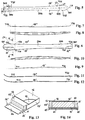
- a ski ( Fig. 1 ) is a relatively elastic and deformable bending-torsion beam, which comprises a front portion, which is bent apart from the ground P, a central portion 200, which is adapted for attachment of a ski shoe, as well as a rear portion 300. Said bending-torsion characteristics of each ski are merely assured thanks to appropriate structure of the ski, in particular to a core 10 ( Figs. 13 and 14 ), below which, on the side facing to the ground P, at least one bottom bearing layer 11 is placed, and above which at least one top bearing layer 12 is arranged.
- Said core 11 is laterally covered by side walls 13' 13", below which ski edges 15', 15" are located, namely the left ski edge 15' and the right ski edge 15", between which a sliding surface 14 is arranged, which is correspondingly located below said bottom bearing layer 11.
- the top bearing layer 12 is covered by a top covering layer 16, which is preferably decorated and intended to protect together with said side walls 13', 13" the core 10 and the bearing layers 11, 12 against the external influences. Thanks to the distance between the bottom and top bearing layer 11, 12, which is maintained by means of said core 10, appropriate bending rigidity of the ski is assured, and also each desired torsion rigidity is obtained by means of corresponding shape and strength of said bearing layers 11, 12.
- Each of said ski edges 15', 15" generally extends continuously along the complete length of the ski, starting from the tip 101 in the front portion 100, throughout the central portion 200 towards the end portion i.e. a tail 301 on the rear portion 300.
- the ski is its central portion 200 deflected away from the ground P, wherein each ski edge 15', 15" extends from the tip 101 towards the deflection in the central portion 200 through a front inflection point T11, T12, and in the rear portion 300 of the ski from said deflection into a relatively straight or even slightly away from the ground P deflected end portion 302 through the rear inflection point T21, T22.
- the left ski edge 15' there are the front inflection point T11 and the rear inflection point T21
- the right ski edge 15" there are the front inflection point T12 and the rear inflection point T22.
- the invention provides that the front portion 100 of the ski ( Figs. 2 an 4) is rotated around the longitudinal axis L0 at a pre-determined angle ⁇ and is deflected apart from the ground P with the radius R along the line L3, which extends inclined with respect to said longitudinal axis L0 passing through the rear portion 300, central portion 200 and the front portion 100 except of the tip 101, namely through the front inflection point T11 of the left ski edge 15' and the front inflection point T12 of the right ski edge 15", by which despite to visually approximately symmetric appearance of the silhouette of the ski in the top view the distance between the front inflection point T11 and the rear inflection point T21 of the left ski edge 15' differs from the distance between the front inflection point T12 and the rear inflection point T22 of the right ski edge 15", and by which the active lengths of both ski edges 15, 15" differ from each other.
- the active length of the left ski edge 15' which is shown in Fig. 9 , corresponds to the distance between inflection points T11, T21, in which the released ski is rest on the ground P.
- the active length of the right ski edge 15" is shown in Fig. 7 and corresponds to distance between inflection points T12, T22, in which the released ski is rest on the ground P.
- the ski according to the invention is characterized by the fact that despite to approximately symmetric appearance of the silhouette of the ski in the top view active lengths of both ski edges 15', 15" differ from each other, so that the distance between the inflection points T11, T21 of the left ski edge 15' in the front area 100 and the rear area 300 differs from the distance between the inflection points T12, T22 on the rear ski edge 15" in the front area 100 and the rear area 300 of the ski.
- said distances between the inflection points T11, T21 on the left ski edge 15' and the inflection points T12, T22 on the rear ski edge 15" are determined in such way that the line L3 through the inflection points T11, T12 of the left and right ski edge 15', 15" in the front portion 100 of the ski together with the line L1, which extends in a transversal direction through the section of said line L3 and the longitudinal axis L0 of the ski, defines an angle ⁇ , while the line L4 through the inflection points T21, T22 of the left and right ski edge 15', 15" in the rear portion 300 of the ski together with line L2 extending in a transversal direction of the ski through the section of said line L4 and the longitudinal axis L0 of the ski defines an angle ⁇ .
- Said angles ⁇ and ⁇ may be equal to each other, which is however not compulsory.
- the shorter active length of the ski edges 15', 15" between each inflection points T11, T12; T21, T22 falls within the area between said transversal lines L1, L2, while the longer active length of the ski edges 15', 15" between the inflection points T11, T12; T21, T22 exceeds the area which is limited with said transversal lines L1, L2.
- the radius of trajectory by turning the ski left differs from the radius of trajectory by turning the ski right, wherein by simultaneously turning each pair of skis the radius of trajectory of each external ski is greater than the radius of trajectory of each internal ski in such extent that by turning each pair of skis, each time internal ski and each time external ski are running approximately equidistant from each other.
- each radius of curvature of the trajectory of the ski by turning depends on each appropriate position of said inflection points T11, T21 on the lefts ski edge 15' as well as the inflection points T12, T22 on the right ski edge 15", namely at least on position of the line L3 between the front inflection points T11, T12 on ski edges 15', 15" and the angle ⁇ of rotation of the tip 101 relatively to the longitudinal axis L0 of the ski.
- said inflection points T11, T12, T21, T22 on both skis in each pair of skis are mirror symmetric.
- the above described concept of the ski is realized in a relatively simple manner and preferably in combination with corresponding weak areas 12', 12" on at least one of said bearing layers 11, 12 adjacent to said inflection points T11, T12 on the ski edge 15', 15" having shorter active length, namely the distance between both inflection points T11, T12, T21, T22. Consequently, said weak area 12', 12" can be established by means of a cutout in the top bearing layer 12 ( Figs.
- the top bearing layer 12 is furnished with two weak areas 12', 12" in the form of cutouts, which are arranged adjacent to the front inflection point T11 and the rear inflection point T21.
- the presence of said weak areas 12', 12" among others results in distribution of the compression towards the ground P in the area of ski edges 15, 15", as shown in Figs 8 and 10 .
- Torsional deformations of the front and rear portion 100, 300 of the ski merely depend on the width of the ski in relevant area, as well as on the torsion rigidity of the ski in said areas 100, 300.
- the torsion rigidity is locally reduced, by which the active length of the ski edge 15', 15" is reduced, along which the compression is generated by the ski edge 15', 15", by which the radius of trajectory of the ski by turning is correspondingly changed.
- said weak areas 12', 12" can be different.
- said weak areas 12', 12" can be completely located on the one side of said longitudinal axis L0, or at least a majority of the surface of the weak area 12', 12" is available on that side of said longitudinal axis L0, which corresponds to the outer side in each pair of skis, while the residual portion of said weak area 12', 12", which should not exceed e.g. 10% to 40% of complete surface thereof, may also be located on the opposite side of the longitudinal axis L0.
- the weak area 12', 12" on at least one of the bearing layers 11, 12 is combined with the presence of further supplemental bearing layers 121, 122, 123, 124, 125, which extend from the central region 200 of the ski towards the front portion 100 and the rear portion 300 and which are each per se ended with inclined edges facing towards said front portion 100 and rear portion 300 of the ski, wherein the angles of inclination of said edges on layers 121, 122, 123, 124, 125 relatively to each transversal line L1, L2 are step-like gradually increasing in a direction towards the front portion 100 and the rear portion 300 of the ski synchronously with arrangement of said weak areas and lines L3, L4 which are inclined relatively to the longitudinal axis L0.
- increasing of said angle of inclination of said edges also introduces asymmetric characteristics and weakening in the sense of local reduction of bending and torsion rigidity of the ski.
- the ski is furnished with a weak area 12', 12" in the form of a recess ( Figs. 17 - 20 ), which extends rectangular with respect to the sliding surface 14 towards the interior of the ski.
- Said weak area 12'in the form of a recess is available on the front portion 100 of the ski in the area of inflection points T11, T12, and extends initially in the longitudinal direction of the ski apart from the first ski edge 15' towards the tip 101, upon which it is deflected in a sinusoidal manner or in the shape of letter S in order to pass the longitudinal axis L0 of the ski in a direction towards the opposite ski edge 15" and continues apart from it towards the tip 101.
- the other weak area 12" in the form of a recess extends along the rear portion 300 of the ski, initially in the longitudinal direction of the ski and apart from the first ski edge 15' towards the tail 301, upon which it passes the longitudinal axis L0 of the ski in the area of a sinusoidal or S-shaped transition in order to continue apart from the second ski edge 15" in a direction towards the tail 301 on the rear portion 300 of the ski.
- the first possible variation provides that such weak area 12', 12" in the form of a recess is foreseen exclusively in the top bearing layer 12 ( Fig. 18 ); the second possible variation ( Fig.
Landscapes
- Fittings On The Vehicle Exterior For Carrying Loads, And Devices For Holding Or Mounting Articles (AREA)
- Footwear And Its Accessory, Manufacturing Method And Apparatuses (AREA)
- Laminated Bodies (AREA)
- Stereoscopic And Panoramic Photography (AREA)
- Cameras In General (AREA)
Claims (10)
- Ski, der asymmetrische Merkmale aufweist und Folgendes umfasst :einen vorderen Abschnitt (100) mit einer Spitze (101), die um einen zweckmäßigen Radius (R) vom Boden (P) fort gebogen ist, einen mittleren Abschnitt (200), an dem eine geeignete Skibindung anzubringen ist, die dafür verwendet wird, einen Skischuh mit dem Ski zu verbinden, sowie einen hinteren Abschnitt (300) mit einem Hinterende (301),wobei ein solcher Ski, in einem Querschnitt entlang jeder Transversallinie (L1, L2) gesehen, die sich rechtwinklig zu seiner Längsachse (L0) erstreckt, einen Kern (10) umfasst, der einerseits mit mindestens einer unteren Tragschicht (11) verbunden ist, die an seiner Unterseite angeordnet ist, die dem Boden (P) zugewandt ist, und andererseits mit mindestens einer oberen Tragschicht (12) verbunden ist, die auf seiner Oberseite angeordnet ist, die dem Boden (P) abgewandt ist,wobei der Kern (10) seitlich durch Seitenwände (13', 13") bedeckt ist, unter denen sich Skiränder (15', 15") befinden, zwischen denen und unter allen entsorgbaren unteren Tragschichten (11) eine Gleitfläche (14) angeordnet ist, während die mindestens eine obere Tragschicht (12) von mindestens einer bevorzugt dekorierten oberen Deckschicht (16) bedeckt ist,und wobei der mittlere Abschnitt (200) des Skis so vom Boden (P) fort gebogen ist, dass der frei gegebene Ski auf dem Boden (P) aufliegt: im Bereich beider Skiränder (15', 15") und der Gleitfläche (14) in der Region von Bogenwechselpunkten (T11, T12; T21, T22) auf den Skirändern (15', 15") mindestens ungefähr innerhalb des Bereichs der maximalen Breite des vorderen Abschnitts (100) und der hinteren Abschnitt (300) des Skis, und zwar entlang des linken Skirandes (15') im vorderen Bogenwechselpunkt (T11) zwischen der Spitze (101) und dem gebogenen mittleren Abschnitt (200), sowie im hinteren Bogenwechselpunkt (T21) zwischen dem gebogenen mittleren Abschnitt (200) und dem Hinterende (301) am hinteren Abschnitt (300) des Skis, und entlang des rechten Skirandes (15") im vorderen Bogenwechselpunkt (T12) zwischen der Spitze (101) und dem gebogenen mittleren Abschnitt (200); sowie im hinteren Bogenwechselpunkt (T22) zwischen dem gebogenen mittleren Abschnitt (200) und dem Hinterende (301) am hinteren Abschnitt (300) des Skis, wobei der Ski im Bereich der Spitze (101) in einem vorgegebenen Dinkel (ϕ) um seine Längsachse (L0) gedreht ist, und darüber hinaus entlang der Linie (L3) über den gesamten vorderen Bogenwechselpunkt (T11) am linken Skirand (15') und den gesamten vorderen Bogenwechselpunkt (T12) am rechten Skirand (15") um einen Radius (R) vom Boden (P) fort gebogen ist, wobei sich die Linie mit Bezug auf die Längsachse (L0) geneigt erstreckt, die sich entlang des hinteren Abschnitts (300), des mittleren Abschnitts (200) und des vorderen Abschnitts (100) des Skis, mit Ausnahme der Spitze (101), so erstreckt, dass trotz einer visuell symmetrischen Silhouette des Skis in seiner Draufsicht die Distanz zwischen dem vorderen Bogenwechselpunkt (T11) und dem hinteren Bogenwechselpunkt (T21) am linken Skirand (15') eine andere ist als die Distanz zwischen dem vorderen Bogenwechselpunkt (T1") und dem hinteren Bogenwechselpunkt (T2") am rechten Skirand (15"), dergestalt, dass die aktiven Längen beider Skisränder (15', 15") voneinander verschieden sind, wobei in jedem Paar Ski die aktive Länge des Skirandes (15', 15"), der auf der Innenseite des Skis angeordnet ist, länger ist als die aktive Länge auf der Außenseite des Skis, undwobei die Distanzen zwischen dem vorderen Bogenwechselpunkt (T11) und dem hinteren Bogenwechselpunkt (T21) am linken Skirand (15') und zwischen dem vorderen Bogenwechselpunkt (T12) und dem hinteren Bogenwechselpunkt (T22) am rechten Skirand (15') in einer solchen Weise festgelegt sind, dass die Linie (L3), die sich durch beide vorderen Bogenwechselpunkte (T11, T12) am linken und am rechten Skirand (15', 15") im vorderen Abschnitt (100) des Skis erstreckt, und die Linie (L1), die sich quer, d. h. senkrecht, zur Längsachse (L0) des Skis und parallel zur Gleitfläche (14) erstreckt, einen vorgegebenen ersten Winkel (α) definieren, unddass die Linie (L4), die sich durch beide hinteren Bogenwechselpunkte (T21, T22) am linken und am rechten Skirand (15', 15") am hinteren Abschnitt (300) des Skis erstreckt, und die Linie (L2), die sich quer, d. h. senkrecht, zur Längsachse (L0) des Skis und parallel zur Gleitfläche (14) erstreckt, einen vorgegebenen zweiten Winkel (β) definieren,wobei der erste und der zweite Winkel (α, β) einander gleich sind, oder wobei der erste und der zweite Winkel (α, β) voneinander verschieden sind, und wobei der Bereich zwischen den Bogenwechselpunkten (T11, T12; T21, T22) an jedem Skirand der eine kleinere aktive Länge hat, in dem durch die Querlinien (L1, L2) begrenzten Bereich angeordnet ist, während im Gegensatz dazu der Bereich zwischen den Bogenwechselpunkten (T11, T12; T21, T22) an jedem Skirand (15', 15"), der eine größere aktive Länge hat, sich über den Bereich hinaus erstreckt, der durch die Querfinien (L1, L2) beschränkt wird,und wobei jeder gewünschte Krümmungsradius der Trajektorie durch Links- oder Rechtsdrehen des Skis durch Definieren der Linie (L3), um die die Spitze (101) relativ zur Längsachse (L0) des Skis gebogen ist, und zwar durch Festlegen der Position der Bogenwechselpunkte (T11, T21) am linken Skirand (15') und der Bogenwechselpunkte (T12, T22) am rechten Skirand (15"), so vorgegeben ist, dass durch Drehen jedes Paar Ski aufgrund verschiedener effektiver Längen zwischen jedem Paar Bogenwechselpunkte (T11, T21; T12, T'22) an den Skirändern (15', 15") der Krümmungsradius der Trajektorie jedes äußeren Skis größer ist als der Krümmungsradius der Trajektorie jedes inneren Skis, wobei die Bogenwechselpunkte (T11, T21; T12, T22) an beiden Ski in jedem Paar Ski spiegelsymmetrisch sind,dadurch gekennzeichnet, dass für die Zwecke des Erhaltens verschiedener aktiver Längen des linken Skirandes (15') und des rechten Skirandes (15"), und zwar der Distanzen zwischen dem vorderen Bogenwechselpunkt (T11) und dem hinteren Bogenwechselpunkt (T21) am linken Skirand (15') und zwischen dem vorderen Bogenwechselpunkt (T12) und dem hinteren Bogenwechselpunkt (T22) am rechten Skirand (15"), ein lokaler geschwächter Bereich (12', 12") an mindestens einer der Tragschichten (11, 12) in der Region von Bogenwechselpunkten (T11, T21; T12, T22) an jenem Skirand (15', 15") vorgesehen ist, der eine kürzere aktive Länge haben soll, wodurch sich entsprechend auch die Verteilungen der Kompression beider Skisränder (15', 15") in Richtung des Bodens (P) voneinander unterscheiden.
- Ski nach Anspruch 1, dadurch gekennzeichnet, dass der lokale geschwächte Bereich (12') im vorderen Abschnitt (100) des Skis vorgesehen ist, und zwar in der Region des vorderen Bogenwechselipunktes (T11, T12) des Skirandes (15', 15"), der eine kürzere aktive Länge aufweist, und dass mindestens ein weiterer geschwächter Bereich (12") im hinteren Abschnitt (300) des Skis vorgesehen ist, und zwar in der Region des hinteren Bogenwechselpunktes (T21, T22) des Skirandes (15', 15"), der eine kürzere aktive Länge aufweist, so dass die aktive Länge des relevanten Skirandes (15', 15") mindestens ungefähr der Distanz zwischen den lokalen geschwächten Bereichen (12', 12") entspricht.
- Ski nach Anspruch 1 oder 2, dadurch gekennzeichnet, dass der lokale geschwächte Bereich (12', 12") ein Ausschnitt in der oberen Tragschicht (12) des Skis ist.
- Ski nach Anspruch 1 oder 2, dadurch gekennzeichnet, dass der lokale geschwächte Bereich (12', 12") ein Ausschnitt in der oberen Tragschicht (12) und außerdem in der unteren Tragschicht (11) des Skis ist.
- Ski nach Anspruch 3 oder 4, dadurch gekennzeichnet, dass die obere Tragschicht (12) des Skis, die mit einem lokalen geschwächten Bereich (12') ausgestattet ist, der im vorderen Abschnitt (100) des Skis angeordnet ist, sowie mit dem lokalen geschwächten Bereich (12") ausgestattet ist, der im hinteren Abschnitt (300) des Skis angeordnet ist, des Weiteren mit mindestens einer Ergänzungstragschicht (121, 122, 123, 124, 125) kombiniert ist, die geneigte Endabschnitte aufweist, wobei die Länge jeder oberen Ergänzungstragschicht (121, 122, 123, 124, 125) kleiner ist als die Länge jeder unteren Ergänzungstragschicht (121, 122, 123, 124, 125), und wobei jeder geneigte Endabschnitt in einer solchen Weise geschnitten ist, dass die Länge jeder Ergänzungstragschicht (121, 122, 123, 124, 125) auf jener Seite mit Bezug auf die Längsachse (L0) des Skis, wo sich der lokale geschwächte Bereich befindet, Kleiner ist als seine Länge auf der gegenüberliegenden Seite der Längsachse (L0).
- Ski nach Anspruch 1, dadurch gekennzeichnet, dass der lokale geschwächte Bereich (12'), der im vorderen Abschnitt (100) des Skis in der Region des vorderen Bogenwechselpunktes (T11, T12) an dem Skirand (15', 15") vorgesehen ist, der eine kürzere aktive Länge aufweist, sowie mindestens ein weiterer lokaler geschwächten Bereich (12"), der im hinteren Abschnitt (300) des Skis in der Region des hinteren Bogenwechselpunktes (T21, T22) an dem Skirand (15', 15") vorgesehen ist, der eine kürzere aktive Länge aufweist, als Aussparungen (12', 12") verfügbar sind, die sich mindestens ungefähr senkrecht mit Bezug auf die Gleitfläche (14) erstrecken.
- Ski nach Anspruch 1, dadurch gekennzeichnet, dass sich der geschwächte Bereich (12') in der Form einer Aussparung, die im vorderen Abschnitt (100) des Skis in der Region des vorderen Bogenwechselpunktes (T11, T12) verfügbar ist, zunächst in der Längsrichtung des Skis von dem ersten Skirand (15') fort und in Richtung der Spitze (101) erstreckt, woraufhin er die Längsachse (L0) des Skis in dem Bereich eines sinus- oder S-förmigen Übergangs passiert und sich weiter in der Längsrichtung des Skis und von dem zweiten Skirand (15") fort in Richtung der Spitze (101) erstreckt, während sich der andere geschwächte Bereich (12") in der Form einer Aussparung, die im hinteren Abschnitt (300) des Skis in der Region des hinteren Bogenwechselpunktes (T21, T22) verfügbar ist, zunächst in der Längsrichtung des Skis von dem ersten Skirand (15') fort und in Richtung des Hinterendes (301) erstreckt, woraufhin er die Längsachse (L0) des Skis im Bereich eines sinus- oder S-förmigen Übergangs passiert und sich weiter in der Längsrichtung des Skis und von dem zweiten Skirand (15") in Richtung des Hinterendes (301) erstreckt.
- Ski nach Anspruch 7, dadurch gekennzeichnet, dass der geschwächte Bereich (12', 12") in der Form einer Aussparung in der oberen Tragschicht (12) des Skis vorgesehen ist.
- Ski nach Anspruch 7, dadurch gekennzeichnet, dass der geschwächte Bereich (12', 12") in der Form einer Aussparung in der oberen Tragschicht (12) und außerdem im Bereich des Kerns (10) des Skis vorgesehen ist.
- Ski nach Anspruch 7, dadurch gekennzeichnet, dass der geschwächte Bereich (12', 12") in der Form einer Aussparung, in der oberen Tragschicht (12) und außerdem im Bereich des Kerns (10) und der unteren Tragschicht (11) des Skis vorgesehen ist.
Applications Claiming Priority (2)
| Application Number | Priority Date | Filing Date | Title |
|---|---|---|---|
| SI201000388A SI23531B (sl) | 2010-11-15 | 2010-11-15 | Smučka z asimetričnimi karakteristikami |
| PCT/SI2011/000062 WO2012067589A1 (en) | 2010-11-15 | 2011-11-07 | Ski having asymmetric characteristics |
Publications (2)
| Publication Number | Publication Date |
|---|---|
| EP2640478A1 EP2640478A1 (de) | 2013-09-25 |
| EP2640478B1 true EP2640478B1 (de) | 2016-03-30 |
Family
ID=43799302
Family Applications (1)
| Application Number | Title | Priority Date | Filing Date |
|---|---|---|---|
| EP11804833.9A Active EP2640478B1 (de) | 2010-11-15 | 2011-11-07 | Asymmetrischer ski |
Country Status (6)
| Country | Link |
|---|---|
| US (1) | US8967655B2 (de) |
| EP (1) | EP2640478B1 (de) |
| JP (1) | JP5812543B2 (de) |
| DE (1) | DE202011001173U1 (de) |
| SI (1) | SI23531B (de) |
| WO (1) | WO2012067589A1 (de) |
Families Citing this family (3)
| Publication number | Priority date | Publication date | Assignee | Title |
|---|---|---|---|---|
| WO2014169238A1 (en) * | 2013-04-11 | 2014-10-16 | Digimarc Corporation | Methods for object recognition and related arrangements |
| DE102017125770A1 (de) * | 2016-12-29 | 2018-07-05 | Völkl Sports GmbH & Co. KG | Untergurt mit Klammereffekt |
| US11452931B2 (en) * | 2019-03-08 | 2022-09-27 | Völkl Sports Gmbh | Sliding board with fiber composite material |
Family Cites Families (28)
| Publication number | Priority date | Publication date | Assignee | Title |
|---|---|---|---|---|
| US2510794A (en) * | 1946-11-01 | 1950-06-06 | Beerli Louis | Ski having concave sides |
| DE2353011C2 (de) | 1973-10-23 | 1981-10-08 | Kienzle Apparate Gmbh, 7730 Villingen-Schwenningen | Anordnung zur stetigen Funktionskontrolle der Aufzeichnungsmittel eines Fahrtschreibers |
| US4343485A (en) * | 1979-03-08 | 1982-08-10 | Ski World, Inc. | Reverse camber ski |
| AT372860B (de) * | 1981-12-03 | 1983-11-25 | Fischer Gmbh | Schipaar |
| JPS62113584U (de) * | 1986-01-10 | 1987-07-20 | ||
| JPS6311076U (de) * | 1986-07-10 | 1988-01-25 | ||
| FR2611518B1 (fr) * | 1987-02-27 | 1989-11-17 | Salomon Sa | Ski a amortissement reparti |
| CH681061A5 (en) | 1989-10-19 | 1993-01-15 | Haldemann Ag | Ski with progressively asymmetric torsion rigidity - having upper plate whose centre part is same width as ski's base and whose outer edges are angled inwards towards ends |
| FR2659562B1 (fr) * | 1990-03-14 | 1992-06-12 | Rossignol Sa | Planche de neige de type ski alpin ou surf de neige. |
| FR2683734B1 (fr) * | 1991-11-19 | 1994-01-07 | Rossignol Sa | Ski en forme, de section non rectangulaire. |
| FR2684886B1 (fr) * | 1991-12-13 | 1994-04-01 | Salomon Sa | Ski a face superieure de largeur variable. |
| JPH0733381U (ja) * | 1993-11-26 | 1995-06-20 | 株式会社カザマスキー | 左右非対称スキー |
| FR2713100B1 (fr) | 1993-11-30 | 1996-01-05 | Rossignol Sa | Ski. |
| FR2734489B1 (fr) * | 1995-05-22 | 1997-07-04 | Rossignol Sa | Planche de glisse sur neige "a demi-coque", pourvue de chants de support de la coque |
| JPH0975498A (ja) * | 1995-09-07 | 1997-03-25 | Nishizawa:Kk | スキー |
| US6499758B1 (en) * | 1998-03-20 | 2002-12-31 | William H. Bollman | Egonomic sportsboard |
| US6394483B2 (en) * | 1997-11-19 | 2002-05-28 | North Shore Partners | Snowboard body |
| US6612605B2 (en) * | 1999-09-29 | 2003-09-02 | K-2 Corporation | Integrated modular glide board |
| FR2832643B1 (fr) * | 2001-11-27 | 2004-01-16 | Rossignol Sa | Perfectionnement pour planche de glisse sur neige |
| AU2002364520A1 (en) * | 2001-12-04 | 2003-06-17 | Gen-X Sports Sarl | Ski |
| FR2855427B1 (fr) | 2003-06-02 | 2005-08-26 | Salomon Sa | Ski prevu pour la pratique du ski alpin |
| DE10359228A1 (de) * | 2003-12-17 | 2005-07-14 | Kneissl Tirol Gmbh | Schneegleitgerät, insbesondere Carvingski |
| SI22083B (sl) * | 2005-07-18 | 2009-12-31 | Elan, D.O.O. | Smučka ali snežna deska z izboljšano torzijsko togostjo |
| DE102006019961B4 (de) * | 2006-04-28 | 2008-01-10 | Epcos Ag | Elektroakustisches Bauelement |
| US7690674B2 (en) * | 2006-08-10 | 2010-04-06 | Armada Skis, Inc. | Snow riding implement |
| FR2908665B1 (fr) * | 2006-11-22 | 2009-03-20 | Salomon Sa | Ski |
| US7798514B2 (en) * | 2008-04-10 | 2010-09-21 | Never Summer Industries, Inc. | Cambered snowboard |
| CH701003B1 (de) * | 2009-05-06 | 2012-03-15 | Zai Ag | Schneegleitbrett. |
-
2010
- 2010-11-15 SI SI201000388A patent/SI23531B/sl active Search and Examination
-
2011
- 2011-01-04 DE DE202011001173U patent/DE202011001173U1/de not_active Expired - Lifetime
- 2011-11-07 JP JP2013538693A patent/JP5812543B2/ja active Active
- 2011-11-07 WO PCT/SI2011/000062 patent/WO2012067589A1/en not_active Ceased
- 2011-11-07 EP EP11804833.9A patent/EP2640478B1/de active Active
- 2011-11-07 US US13/885,367 patent/US8967655B2/en active Active
Also Published As
| Publication number | Publication date |
|---|---|
| JP2013542040A (ja) | 2013-11-21 |
| DE202011001173U1 (de) | 2011-03-17 |
| US8967655B2 (en) | 2015-03-03 |
| EP2640478A1 (de) | 2013-09-25 |
| US20130270796A1 (en) | 2013-10-17 |
| WO2012067589A1 (en) | 2012-05-24 |
| SI23531A (sl) | 2012-05-31 |
| SI23531B (sl) | 2019-06-28 |
| JP5812543B2 (ja) | 2015-11-17 |
Similar Documents
| Publication | Publication Date | Title |
|---|---|---|
| US10486322B2 (en) | Unitary razor blade and shaving razor cartridge using same | |
| US6695714B1 (en) | Iron-Type golf club head with beveled sole | |
| US9067125B2 (en) | Skateboard | |
| US5431427A (en) | Ski having a binding mounting plate fitted above the ski body, at least partly at a distance therefrom and in fixed relationship thereto | |
| US20160354651A1 (en) | Golf Clubs | |
| USRE36586E (en) | Shaped ski of non-rectangular cross section | |
| CA2750507C (en) | Hockey stick blade | |
| US20020014757A1 (en) | Gliding board | |
| US5280943A (en) | Ski with a ribbed upper surface | |
| US9656137B2 (en) | Two-part hockey stick | |
| EP2640478B1 (de) | Asymmetrischer ski | |
| JP6503714B2 (ja) | ゴルフクラブヘッド | |
| US6293563B1 (en) | Chassis for a gliding sport element, such as a skate, and a gliding element including such chassis | |
| US20020089149A1 (en) | Gliding board with varying bending properties | |
| US20110272920A1 (en) | Gliding board | |
| US6059306A (en) | Glide board intended for snowboarding | |
| US20010052687A1 (en) | Alpine ski | |
| US10905937B2 (en) | Reinforcing frame for a ski | |
| US7837217B2 (en) | Ski or snowboard having improved torsional rigidity | |
| EP1848515B1 (de) | Snowboard und skier für den gebrauch in pulverschnee | |
| DK2583542T3 (en) | treatment Stand | |
| CN111888739B (zh) | 高尔夫球杆头以及高尔夫球杆 | |
| JP4560674B2 (ja) | スノーボード用補強プレート及びスノーボード | |
| US20010042969A1 (en) | Alpine ski | |
| KR20250165216A (ko) | 가변 페이스 두께를 갖는 골프 클럽 헤드 |
Legal Events
| Date | Code | Title | Description |
|---|---|---|---|
| PUAI | Public reference made under article 153(3) epc to a published international application that has entered the european phase |
Free format text: ORIGINAL CODE: 0009012 |
|
| 17P | Request for examination filed |
Effective date: 20130617 |
|
| AK | Designated contracting states |
Kind code of ref document: A1 Designated state(s): AL AT BE BG CH CY CZ DE DK EE ES FI FR GB GR HR HU IE IS IT LI LT LU LV MC MK MT NL NO PL PT RO RS SE SI SK SM TR |
|
| DAX | Request for extension of the european patent (deleted) | ||
| GRAP | Despatch of communication of intention to grant a patent |
Free format text: ORIGINAL CODE: EPIDOSNIGR1 |
|
| INTG | Intention to grant announced |
Effective date: 20151211 |
|
| GRAS | Grant fee paid |
Free format text: ORIGINAL CODE: EPIDOSNIGR3 |
|
| GRAA | (expected) grant |
Free format text: ORIGINAL CODE: 0009210 |
|
| AK | Designated contracting states |
Kind code of ref document: B1 Designated state(s): AL AT BE BG CH CY CZ DE DK EE ES FI FR GB GR HR HU IE IS IT LI LT LU LV MC MK MT NL NO PL PT RO RS SE SI SK SM TR |
|
| REG | Reference to a national code |
Ref country code: GB Ref legal event code: FG4D |
|
| REG | Reference to a national code |
Ref country code: CH Ref legal event code: EP |
|
| REG | Reference to a national code |
Ref country code: AT Ref legal event code: REF Ref document number: 784728 Country of ref document: AT Kind code of ref document: T Effective date: 20160415 |
|
| REG | Reference to a national code |
Ref country code: IE Ref legal event code: FG4D |
|
| REG | Reference to a national code |
Ref country code: DE Ref legal event code: R096 Ref document number: 602011024713 Country of ref document: DE |
|
| REG | Reference to a national code |
Ref country code: LT Ref legal event code: MG4D |
|
| PG25 | Lapsed in a contracting state [announced via postgrant information from national office to epo] |
Ref country code: FI Free format text: LAPSE BECAUSE OF FAILURE TO SUBMIT A TRANSLATION OF THE DESCRIPTION OR TO PAY THE FEE WITHIN THE PRESCRIBED TIME-LIMIT Effective date: 20160330 Ref country code: GR Free format text: LAPSE BECAUSE OF FAILURE TO SUBMIT A TRANSLATION OF THE DESCRIPTION OR TO PAY THE FEE WITHIN THE PRESCRIBED TIME-LIMIT Effective date: 20160701 Ref country code: NO Free format text: LAPSE BECAUSE OF FAILURE TO SUBMIT A TRANSLATION OF THE DESCRIPTION OR TO PAY THE FEE WITHIN THE PRESCRIBED TIME-LIMIT Effective date: 20160630 Ref country code: HR Free format text: LAPSE BECAUSE OF FAILURE TO SUBMIT A TRANSLATION OF THE DESCRIPTION OR TO PAY THE FEE WITHIN THE PRESCRIBED TIME-LIMIT Effective date: 20160330 |
|
| REG | Reference to a national code |
Ref country code: NL Ref legal event code: MP Effective date: 20160330 |
|
| PG25 | Lapsed in a contracting state [announced via postgrant information from national office to epo] |
Ref country code: SE Free format text: LAPSE BECAUSE OF FAILURE TO SUBMIT A TRANSLATION OF THE DESCRIPTION OR TO PAY THE FEE WITHIN THE PRESCRIBED TIME-LIMIT Effective date: 20160330 Ref country code: RS Free format text: LAPSE BECAUSE OF FAILURE TO SUBMIT A TRANSLATION OF THE DESCRIPTION OR TO PAY THE FEE WITHIN THE PRESCRIBED TIME-LIMIT Effective date: 20160330 Ref country code: LV Free format text: LAPSE BECAUSE OF FAILURE TO SUBMIT A TRANSLATION OF THE DESCRIPTION OR TO PAY THE FEE WITHIN THE PRESCRIBED TIME-LIMIT Effective date: 20160330 Ref country code: LT Free format text: LAPSE BECAUSE OF FAILURE TO SUBMIT A TRANSLATION OF THE DESCRIPTION OR TO PAY THE FEE WITHIN THE PRESCRIBED TIME-LIMIT Effective date: 20160330 |
|
| PG25 | Lapsed in a contracting state [announced via postgrant information from national office to epo] |
Ref country code: NL Free format text: LAPSE BECAUSE OF FAILURE TO SUBMIT A TRANSLATION OF THE DESCRIPTION OR TO PAY THE FEE WITHIN THE PRESCRIBED TIME-LIMIT Effective date: 20160330 |
|
| REG | Reference to a national code |
Ref country code: FR Ref legal event code: PLFP Year of fee payment: 6 |
|
| PG25 | Lapsed in a contracting state [announced via postgrant information from national office to epo] |
Ref country code: IS Free format text: LAPSE BECAUSE OF FAILURE TO SUBMIT A TRANSLATION OF THE DESCRIPTION OR TO PAY THE FEE WITHIN THE PRESCRIBED TIME-LIMIT Effective date: 20160730 Ref country code: PL Free format text: LAPSE BECAUSE OF FAILURE TO SUBMIT A TRANSLATION OF THE DESCRIPTION OR TO PAY THE FEE WITHIN THE PRESCRIBED TIME-LIMIT Effective date: 20160330 Ref country code: EE Free format text: LAPSE BECAUSE OF FAILURE TO SUBMIT A TRANSLATION OF THE DESCRIPTION OR TO PAY THE FEE WITHIN THE PRESCRIBED TIME-LIMIT Effective date: 20160330 |
|
| PG25 | Lapsed in a contracting state [announced via postgrant information from national office to epo] |
Ref country code: CZ Free format text: LAPSE BECAUSE OF FAILURE TO SUBMIT A TRANSLATION OF THE DESCRIPTION OR TO PAY THE FEE WITHIN THE PRESCRIBED TIME-LIMIT Effective date: 20160330 Ref country code: SM Free format text: LAPSE BECAUSE OF FAILURE TO SUBMIT A TRANSLATION OF THE DESCRIPTION OR TO PAY THE FEE WITHIN THE PRESCRIBED TIME-LIMIT Effective date: 20160330 Ref country code: ES Free format text: LAPSE BECAUSE OF FAILURE TO SUBMIT A TRANSLATION OF THE DESCRIPTION OR TO PAY THE FEE WITHIN THE PRESCRIBED TIME-LIMIT Effective date: 20160330 Ref country code: RO Free format text: LAPSE BECAUSE OF FAILURE TO SUBMIT A TRANSLATION OF THE DESCRIPTION OR TO PAY THE FEE WITHIN THE PRESCRIBED TIME-LIMIT Effective date: 20160330 Ref country code: PT Free format text: LAPSE BECAUSE OF FAILURE TO SUBMIT A TRANSLATION OF THE DESCRIPTION OR TO PAY THE FEE WITHIN THE PRESCRIBED TIME-LIMIT Effective date: 20160801 Ref country code: SK Free format text: LAPSE BECAUSE OF FAILURE TO SUBMIT A TRANSLATION OF THE DESCRIPTION OR TO PAY THE FEE WITHIN THE PRESCRIBED TIME-LIMIT Effective date: 20160330 |
|
| PG25 | Lapsed in a contracting state [announced via postgrant information from national office to epo] |
Ref country code: BE Free format text: LAPSE BECAUSE OF FAILURE TO SUBMIT A TRANSLATION OF THE DESCRIPTION OR TO PAY THE FEE WITHIN THE PRESCRIBED TIME-LIMIT Effective date: 20160330 Ref country code: IT Free format text: LAPSE BECAUSE OF FAILURE TO SUBMIT A TRANSLATION OF THE DESCRIPTION OR TO PAY THE FEE WITHIN THE PRESCRIBED TIME-LIMIT Effective date: 20160330 |
|
| REG | Reference to a national code |
Ref country code: DE Ref legal event code: R097 Ref document number: 602011024713 Country of ref document: DE |
|
| PG25 | Lapsed in a contracting state [announced via postgrant information from national office to epo] |
Ref country code: DK Free format text: LAPSE BECAUSE OF FAILURE TO SUBMIT A TRANSLATION OF THE DESCRIPTION OR TO PAY THE FEE WITHIN THE PRESCRIBED TIME-LIMIT Effective date: 20160330 |
|
| PLBE | No opposition filed within time limit |
Free format text: ORIGINAL CODE: 0009261 |
|
| STAA | Information on the status of an ep patent application or granted ep patent |
Free format text: STATUS: NO OPPOSITION FILED WITHIN TIME LIMIT |
|
| 26N | No opposition filed |
Effective date: 20170103 |
|
| PG25 | Lapsed in a contracting state [announced via postgrant information from national office to epo] |
Ref country code: SI Free format text: LAPSE BECAUSE OF FAILURE TO SUBMIT A TRANSLATION OF THE DESCRIPTION OR TO PAY THE FEE WITHIN THE PRESCRIBED TIME-LIMIT Effective date: 20160330 |
|
| REG | Reference to a national code |
Ref country code: CH Ref legal event code: PL |
|
| GBPC | Gb: european patent ceased through non-payment of renewal fee |
Effective date: 20161107 |
|
| PG25 | Lapsed in a contracting state [announced via postgrant information from national office to epo] |
Ref country code: CH Free format text: LAPSE BECAUSE OF NON-PAYMENT OF DUE FEES Effective date: 20161130 Ref country code: LI Free format text: LAPSE BECAUSE OF NON-PAYMENT OF DUE FEES Effective date: 20161130 |
|
| REG | Reference to a national code |
Ref country code: IE Ref legal event code: MM4A |
|
| PG25 | Lapsed in a contracting state [announced via postgrant information from national office to epo] |
Ref country code: LU Free format text: LAPSE BECAUSE OF NON-PAYMENT OF DUE FEES Effective date: 20161130 |
|
| REG | Reference to a national code |
Ref country code: FR Ref legal event code: PLFP Year of fee payment: 7 |
|
| PG25 | Lapsed in a contracting state [announced via postgrant information from national office to epo] |
Ref country code: GB Free format text: LAPSE BECAUSE OF NON-PAYMENT OF DUE FEES Effective date: 20161107 Ref country code: IE Free format text: LAPSE BECAUSE OF NON-PAYMENT OF DUE FEES Effective date: 20161107 |
|
| PG25 | Lapsed in a contracting state [announced via postgrant information from national office to epo] |
Ref country code: HU Free format text: LAPSE BECAUSE OF FAILURE TO SUBMIT A TRANSLATION OF THE DESCRIPTION OR TO PAY THE FEE WITHIN THE PRESCRIBED TIME-LIMIT; INVALID AB INITIO Effective date: 20111107 Ref country code: CY Free format text: LAPSE BECAUSE OF FAILURE TO SUBMIT A TRANSLATION OF THE DESCRIPTION OR TO PAY THE FEE WITHIN THE PRESCRIBED TIME-LIMIT Effective date: 20160330 |
|
| PG25 | Lapsed in a contracting state [announced via postgrant information from national office to epo] |
Ref country code: MC Free format text: LAPSE BECAUSE OF FAILURE TO SUBMIT A TRANSLATION OF THE DESCRIPTION OR TO PAY THE FEE WITHIN THE PRESCRIBED TIME-LIMIT Effective date: 20160330 Ref country code: MK Free format text: LAPSE BECAUSE OF FAILURE TO SUBMIT A TRANSLATION OF THE DESCRIPTION OR TO PAY THE FEE WITHIN THE PRESCRIBED TIME-LIMIT Effective date: 20160330 |
|
| PG25 | Lapsed in a contracting state [announced via postgrant information from national office to epo] |
Ref country code: BG Free format text: LAPSE BECAUSE OF FAILURE TO SUBMIT A TRANSLATION OF THE DESCRIPTION OR TO PAY THE FEE WITHIN THE PRESCRIBED TIME-LIMIT Effective date: 20160330 |
|
| PG25 | Lapsed in a contracting state [announced via postgrant information from national office to epo] |
Ref country code: MT Free format text: LAPSE BECAUSE OF NON-PAYMENT OF DUE FEES Effective date: 20161107 |
|
| PG25 | Lapsed in a contracting state [announced via postgrant information from national office to epo] |
Ref country code: AL Free format text: LAPSE BECAUSE OF FAILURE TO SUBMIT A TRANSLATION OF THE DESCRIPTION OR TO PAY THE FEE WITHIN THE PRESCRIBED TIME-LIMIT Effective date: 20160330 Ref country code: TR Free format text: LAPSE BECAUSE OF FAILURE TO SUBMIT A TRANSLATION OF THE DESCRIPTION OR TO PAY THE FEE WITHIN THE PRESCRIBED TIME-LIMIT Effective date: 20160330 |
|
| REG | Reference to a national code |
Ref country code: AT Ref legal event code: UEP Ref document number: 784728 Country of ref document: AT Kind code of ref document: T Effective date: 20160330 |
|
| P01 | Opt-out of the competence of the unified patent court (upc) registered |
Effective date: 20230609 |
|
| PGFP | Annual fee paid to national office [announced via postgrant information from national office to epo] |
Ref country code: DE Payment date: 20241119 Year of fee payment: 14 |
|
| PGFP | Annual fee paid to national office [announced via postgrant information from national office to epo] |
Ref country code: FR Payment date: 20241106 Year of fee payment: 14 |
|
| PGFP | Annual fee paid to national office [announced via postgrant information from national office to epo] |
Ref country code: AT Payment date: 20241118 Year of fee payment: 14 |