EP2639764B1 - Interactive 3-D examination of root fractures - Google Patents
Interactive 3-D examination of root fractures Download PDFInfo
- Publication number
- EP2639764B1 EP2639764B1 EP13001119.0A EP13001119A EP2639764B1 EP 2639764 B1 EP2639764 B1 EP 2639764B1 EP 13001119 A EP13001119 A EP 13001119A EP 2639764 B1 EP2639764 B1 EP 2639764B1
- Authority
- EP
- European Patent Office
- Prior art keywords
- tooth
- image
- operator
- subject tooth
- subject
- Prior art date
- Legal status (The legal status is an assumption and is not a legal conclusion. Google has not performed a legal analysis and makes no representation as to the accuracy of the status listed.)
- Active
Links
- 230000002452 interceptive effect Effects 0.000 title claims description 10
- 238000005520 cutting process Methods 0.000 claims description 23
- 238000000034 method Methods 0.000 claims description 23
- 238000007408 cone-beam computed tomography Methods 0.000 claims description 22
- 238000009877 rendering Methods 0.000 claims description 21
- 210000004262 dental pulp cavity Anatomy 0.000 claims description 9
- 230000000694 effects Effects 0.000 claims description 4
- 206010062544 Tooth fracture Diseases 0.000 claims description 3
- 230000004044 response Effects 0.000 claims description 3
- 238000003384 imaging method Methods 0.000 description 25
- 230000011218 segmentation Effects 0.000 description 22
- 238000010586 diagram Methods 0.000 description 9
- 238000012545 processing Methods 0.000 description 8
- 238000003860 storage Methods 0.000 description 8
- 238000004422 calculation algorithm Methods 0.000 description 7
- 238000004590 computer program Methods 0.000 description 5
- 230000003287 optical effect Effects 0.000 description 5
- 210000000988 bone and bone Anatomy 0.000 description 4
- 239000003086 colorant Substances 0.000 description 4
- 230000005856 abnormality Effects 0.000 description 3
- 230000008901 benefit Effects 0.000 description 3
- 230000008859 change Effects 0.000 description 3
- 238000002591 computed tomography Methods 0.000 description 3
- 238000001514 detection method Methods 0.000 description 3
- 238000002059 diagnostic imaging Methods 0.000 description 3
- 230000003993 interaction Effects 0.000 description 3
- 230000005855 radiation Effects 0.000 description 3
- 238000002601 radiography Methods 0.000 description 3
- 210000001519 tissue Anatomy 0.000 description 3
- 238000013459 approach Methods 0.000 description 2
- 238000004891 communication Methods 0.000 description 2
- 238000012937 correction Methods 0.000 description 2
- 238000005516 engineering process Methods 0.000 description 2
- 238000001914 filtration Methods 0.000 description 2
- 230000006870 function Effects 0.000 description 2
- 239000000463 material Substances 0.000 description 2
- 239000007787 solid Substances 0.000 description 2
- 239000012536 storage buffer Substances 0.000 description 2
- 238000002560 therapeutic procedure Methods 0.000 description 2
- 238000012800 visualization Methods 0.000 description 2
- 239000000899 Gutta-Percha Substances 0.000 description 1
- 206010061218 Inflammation Diseases 0.000 description 1
- 240000000342 Palaquium gutta Species 0.000 description 1
- 206010000269 abscess Diseases 0.000 description 1
- 238000004458 analytical method Methods 0.000 description 1
- 210000003484 anatomy Anatomy 0.000 description 1
- 230000004397 blinking Effects 0.000 description 1
- 239000000872 buffer Substances 0.000 description 1
- 238000004364 calculation method Methods 0.000 description 1
- 238000013500 data storage Methods 0.000 description 1
- 230000001419 dependent effect Effects 0.000 description 1
- 238000000605 extraction Methods 0.000 description 1
- 229920000588 gutta-percha Polymers 0.000 description 1
- 238000003709 image segmentation Methods 0.000 description 1
- 208000015181 infectious disease Diseases 0.000 description 1
- 230000004054 inflammatory process Effects 0.000 description 1
- 230000007774 longterm Effects 0.000 description 1
- 230000007246 mechanism Effects 0.000 description 1
- 238000005457 optimization Methods 0.000 description 1
- 210000000056 organ Anatomy 0.000 description 1
- 238000003825 pressing Methods 0.000 description 1
- 230000008569 process Effects 0.000 description 1
- 230000006641 stabilisation Effects 0.000 description 1
- 238000011105 stabilization Methods 0.000 description 1
- 238000012549 training Methods 0.000 description 1
- 230000009466 transformation Effects 0.000 description 1
- 238000012795 verification Methods 0.000 description 1
- 238000011179 visual inspection Methods 0.000 description 1
Images


Classifications
-
- A61B6/51—
-
- G—PHYSICS
- G06—COMPUTING; CALCULATING OR COUNTING
- G06T—IMAGE DATA PROCESSING OR GENERATION, IN GENERAL
- G06T7/00—Image analysis
- G06T7/10—Segmentation; Edge detection
- G06T7/162—Segmentation; Edge detection involving graph-based methods
-
- G—PHYSICS
- G06—COMPUTING; CALCULATING OR COUNTING
- G06T—IMAGE DATA PROCESSING OR GENERATION, IN GENERAL
- G06T7/00—Image analysis
-
- G—PHYSICS
- G06—COMPUTING; CALCULATING OR COUNTING
- G06T—IMAGE DATA PROCESSING OR GENERATION, IN GENERAL
- G06T7/00—Image analysis
- G06T7/10—Segmentation; Edge detection
- G06T7/11—Region-based segmentation
-
- G—PHYSICS
- G06—COMPUTING; CALCULATING OR COUNTING
- G06T—IMAGE DATA PROCESSING OR GENERATION, IN GENERAL
- G06T7/00—Image analysis
- G06T7/10—Segmentation; Edge detection
- G06T7/194—Segmentation; Edge detection involving foreground-background segmentation
-
- G—PHYSICS
- G06—COMPUTING; CALCULATING OR COUNTING
- G06T—IMAGE DATA PROCESSING OR GENERATION, IN GENERAL
- G06T2200/00—Indexing scheme for image data processing or generation, in general
- G06T2200/04—Indexing scheme for image data processing or generation, in general involving 3D image data
-
- G—PHYSICS
- G06—COMPUTING; CALCULATING OR COUNTING
- G06T—IMAGE DATA PROCESSING OR GENERATION, IN GENERAL
- G06T2200/00—Indexing scheme for image data processing or generation, in general
- G06T2200/24—Indexing scheme for image data processing or generation, in general involving graphical user interfaces [GUIs]
-
- G—PHYSICS
- G06—COMPUTING; CALCULATING OR COUNTING
- G06T—IMAGE DATA PROCESSING OR GENERATION, IN GENERAL
- G06T2207/00—Indexing scheme for image analysis or image enhancement
- G06T2207/10—Image acquisition modality
- G06T2207/10072—Tomographic images
- G06T2207/10081—Computed x-ray tomography [CT]
-
- G—PHYSICS
- G06—COMPUTING; CALCULATING OR COUNTING
- G06T—IMAGE DATA PROCESSING OR GENERATION, IN GENERAL
- G06T2207/00—Indexing scheme for image analysis or image enhancement
- G06T2207/20—Special algorithmic details
- G06T2207/20072—Graph-based image processing
-
- G—PHYSICS
- G06—COMPUTING; CALCULATING OR COUNTING
- G06T—IMAGE DATA PROCESSING OR GENERATION, IN GENERAL
- G06T2207/00—Indexing scheme for image analysis or image enhancement
- G06T2207/20—Special algorithmic details
- G06T2207/20092—Interactive image processing based on input by user
- G06T2207/20101—Interactive definition of point of interest, landmark or seed
-
- G—PHYSICS
- G06—COMPUTING; CALCULATING OR COUNTING
- G06T—IMAGE DATA PROCESSING OR GENERATION, IN GENERAL
- G06T2207/00—Indexing scheme for image analysis or image enhancement
- G06T2207/30—Subject of image; Context of image processing
- G06T2207/30004—Biomedical image processing
- G06T2207/30036—Dental; Teeth
Definitions
- the invention relates generally to dental imaging, and in particular to a radiographic imaging apparatus for viewing volume images of tooth structures.
- Cone beam computed tomography is an X-ray imaging modality capable of acquiring three-dimensional information of the human anatomy with a substantially lower radiation dose to the patient as compared to conventional medical computed tomography (CT) systems.
- Cone beam CT systems capture volumetric data sets by using a high frame rate digital radiography (DR) detector and an x-ray source, typically affixed to a gantry that rotates about the subject to be imaged, directing, from various points along its orbit around the subject, a divergent cone beam of x-rays toward the subject.
- the CBCT system captures projections throughout the rotation, for example, one 2-D projection image at every degree of rotation.
- the projections are then reconstructed into a 3D volume image using various techniques. Among the most common methods for reconstructing the 3-D volume image are filtered back projection approaches.
- VRF Vertical root fracture
- CBCT CBCT a promising technology for assessment of VRF and other endodontic conditions.
- an infected tooth 20 has an abscess 22 that is to be treated.
- An opening 24 is made in tooth 20 and a tool 28 used to access and remove infected material.
- a plugger 30 then fills root portions of tooth 20 with gutta percha or other suitable material.
- the tooth 20 can then be repaired with a filling 34 or with a crown 36 that is fitted onto a post 38 inserted by the practitioner.
- CBCT imaging can be used to improve detection of VRF and other conditions requiring endodontic treatment, however, difficulties remain.
- Manipulating the CBCT image can be challenging, particularly for practitioners and technicians who are new to volume imaging technology. Isolating the particular views that most distinctly reveal the problem condition can be difficult or frustrating for the practitioner, burdening the user with a time commitment for training and using the CBCT- system.
- An aspect of the present invention is to advance the art of dental imaging, particularly for volume imaging allowing interactive examination of teeth and their root structures.
- embodiments of the present invention allow an operator to select a specific tooth or group of teeth from volume image data and to modify the angle at which the tooth is viewed.
- the operator is also able to page through slices of the tooth from angles other than the standard coronal, sagittal, or axial images provided in conventional volume image presentation.
- Interactive operation allows the operator to progressively improve tooth segmentation used to isolate the data for a particular tooth from other volume image data.
- a method as set forth in claim 1 is provided. Further embodiments of the invention are inter alia shown in the dependent claims.
- a method for 3-D interactive examination of a subject tooth is provided, wherein the method is executed at least in part by a computer and comprises: obtaining volume image data containing at least the subject tooth and background content adjacent to the subject tooth; displaying a first image from the volume data that shows at least the subject tooth and the background content; identifying a portion of the background content in the first image according to a first operator instruction; identifying tooth content for the at least the subject tooth in the first image according to a second operator instruction; segmenting the at least the subject tooth from within the volume data according to the first and second operator instructions; and displaying the segmented subject tooth.
- image refers to multi-dimensional image data that is composed of discrete image elements.
- discrete image elements are picture elements, or pixels.
- volume images also termed volume images, the discrete image elements are volume image elements, or voxels.
- spline is equivalent to a curve, free-form curve, or line.
- a multi-dimensional image can alternately be expressed as a set of nodes and arc-weights.
- the term "IFT” refers to a framework that represents the image data as a set of nodes and arcs-weights, also known as the image foresting transform.
- the terms "viewer”, “user”, and “operator” are considered to be equivalent terms for the person who uses the system and observes and manipulates the displayed view of the volume data for one or more of the patient's teeth.
- the operator can be a dental practitioner or technician or other person
- highlighting for a displayed feature has its conventional meaning as is understood to those skilled in the information and image display arts. In general, highlighting uses some form of localized display enhancement to attract the attention of the viewer. Highlighting a portion of an image, such as an individual organ, bone, or structure, or a path from one chamber to the next, for example, can be achieved in any of a number of ways, including, but not limited to, annotating, displaying a nearby or overlaying symbol, outlining or tracing, display in a different color or at a markedly different intensity or gray scale value than other image or information content, blinking or animation of a portion of a display, or display at higher sharpness or contrast.
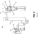
- FIG. 2 shows an imaging apparatus 100 for volume imaging, such as CBCT imaging, in which a succession of two or more 2-D images is obtained and images of adjacent content are processed to form a 3-D or volume image.
- a rotatable mount 130 is provided on a column 118 for imaging a patient 12.
- Mount 130 maintains an x-ray source 110 and a radiation sensor 121 on opposite sides of the head of patient 12 and rotates to orbit source 110 and sensor 121 in a scan pattern about the head.
- Mount 130 rotates about an axis Q that corresponds to a central portion of the patient's head, so that its attached components orbit about the head.
- Sensor 121 a digital radiography sensor according to an embodiment of the present invention, is coupled to mount 130, opposite x-ray source 110 that emits a radiation pattern suitable for CBCT volume imaging.
- An optional head support 136 such as a chin rest or bite element, provides stabilization of the patient's head during image acquisition.
- a computer 106 has an operator interface 104 and a display 108 for accepting operator commands and for display of volume images obtained by imaging apparatus 100.
- Computer 106 with memory 132, is in signal communication with sensor 121 for obtaining image data and provides signals for control of source 110 and, optionally, for control of a rotational actuator 112 for mount 130 components.
- Embodiments of the present invention process images obtained from imaging apparatus 100 to provide a volume image that allows a practitioner to view teeth and supporting structures in detail.
- the volume image data that is obtained from imaging apparatus 100 enable the practitioner to view images of a tooth that can allow assessment of endodontic conditions that can be difficult to detect using conventional radiography images.
- Figure 3A shows a plan view of an image 72 obtained using volume imaging apparatus 100.
- Image 72 can be any slice of the image, as the image slice would appear on display 108 ( Figure 2 ).
- Image 72 is used as a type of index image for markup.
- Figure 3A shows, within image 72 the tooth of interest, a subject tooth 40, that the practitioner would like to view in detail.
- One or more neighboring or adjacent teeth 42 may also be shown.
- Background content 44 is in the area outside of teeth 40 and 42.
- a first operator instruction, a tooth identifier curve or spline 50 indicates the location of tooth content for subject tooth 40.
- a second operator instruction, a background or sculpting curve or spline 52 can be drawn on image 72 outside the border of the subject tooth or within any suitable background area.
- spline 52 indicates picture elements that lie in the background content 44, such as in the area outside of or between teeth 40 and 42. Tooth identifier spline 50 can span a single tooth in the displayed image 72, or can span multiple teeth, as described in more detail subsequently.
- splines 50 and 52 are entered using a touch screen, that is, where display 108 ( Figure 2 ) associated with the imaging apparatus 100 is a touch screen device.
- display 108 Figure 2
- another type of pointer device is used, such as a mouse, stylus, or joystick, for example.
- splines of different colors are used to identify tooth content and differentiate the tooth content from background content for the segmentation algorithm.
- Splines 50 and 52 can be entered in any order; color is used to help differentiate tooth from background content.
- the segmentation algorithm itself may optionally operate on a low-resolution copy of the volume image data.
- Splines 50 and 52 provide sufficient information for IFT-based segmentation of subject tooth 40 from the balance of the volume image data, in real time.
- a 3-D model of subject tooth 40 is displayed side-by-side with highlighted 2-D segmented regions in the slice image, as is shown in the example of Figures 3A and 3B .
- the subject tooth is highlighted on the display screen as verification to the operator. Highlighting can be indicated by change of color, heightened contrast, outlining, or some other display enhancement feature.
- FIG. 3B shows a wireframe view; an operator instruction, such as a keyboard command, toggles between surface rendering and wireframe rendering.
- This view of the 2-D image slices of tooth 40 is provided at an initial view angle.
- This initial view angle may be one of the conventional sagittal, coronal, and axial view angles that are typically used as default view angles for CBCT data or may be a different view angle.
- a 3-D cutting plane is generated automatically in response to the operator instruction and an IFT optimization routine finds a suitable viewing angle that maximizes the number of root canal- and fracture -like pixels in the slice images. This is an initial cutting plane for viewing and paging through slices in the volume image, where both the root canal and the root fracture (if present) are highlighted.
- a 3-D interactive examination phase is then initiated, as shown in Figure 5B , allowing the operator to change the cutting plane's normal vector N for any given oblique orientation.
- the operator is in control of image manipulation. This allows the operator to quickly and confidently examine abnormalities, such as fractures in 3D, without worry about missing the selected tooth.
- control keys are provided to switch quickly between standard view angles. Zoom in/out utilities are also available, using a mouse or other pointer.
- Figure 3C is a logic flow diagram that shows operator interaction with the imaging system for modeling and obtaining a 3-D segmentation for a subject tooth.
- object identification step S110 the operator positions one or more identifier splines over the subject tooth or portion of a tooth or other structure to be modeled.
- background identification step S120 the operator positions one or more background or sculpting splines for marking the background region.
- the system In response to operator entries in steps S110 and S120, the system generates and displays a coarse 3-D model in a model display step S130.
- a looping step S140 the operator has the option to loop back through steps S110 and S120 as needed to refine and improve the results from the system that display in step S130.
- steps S110 and S120 can be performed in any order and can be repeated as many times as needed, with entry of as many identifying and background splines as are useful for providing a suitable 3-D modeling of the subject tooth or other structure.
- the color of a spline indicates its function, either as an indicator or background spline.
- the color of an entered indicator spline determines color that is used for the generated 3-D model that displays.
- On-screen utilities and tools provided with the mouse or other pointer enable changing the color of an entered spline as desired.
- the operator can add additional splines 50 and 52 in order to refine the segmentation provided for subject tooth 40. This feature can help, for example, where the displayed segmentation appears to be inaccurate, such as where other teeth or tissue display with the segmented subject tooth 40.
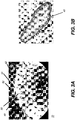
- Figures 4A and 4B show, in schematic form, how different views of the volume data for tooth 40 can be presented and show how a cutting plane 62 can be defined and changed according to embodiments of the present invention.
- a volume image 58 has its slices 60a, 60b, 60c, 60g, and other slices taken along cutting plane 62 having a normal N as shown.
- Figure 4B shows how the same volume image data can be rearranged along a different cutting plane 62' having a corresponding normal N', so that the image content of volume image 58 is formed by slices 61a, 61b, 61c, and the like.
- the same subject tooth 40 can be viewed from alternate angles. Moreover, by paging through slices 60a, 60b, 60c, and the like, the viewer can display a slice that most effectively shows a problem or other point of interest in subject tooth 40. As is shown in Figure 4A , a fissure 66 is most readily visible on slice 60g, obtained at the viewing angle defined by cutting plane 62. Other views of tooth 40 may not show fissure 66 or other anomaly in sufficient detail for assessment of the patient's condition.
- Figures 4A and 4B represent different views of the same volume data.
- the arrangement of voxel data into slices of the appropriate geometry is performed using volume image reconstruction techniques familiar to those skilled in the image processing arts. Paging through successive slices of the volume image can be performed in any of a number of ways, such as by pressing a keyboard key or combination of keys, using a mouse or pointer, or using other appropriate user interface utility.
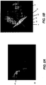
- FIG. 5A shows a slice 60 obtained and displayed from an image of a subject tooth 40, where slice 60 shows a root fracture, such as a VRF described earlier, or other endodontic complication. It can be appreciated that the problem with the tooth that is indicated in Figure 5A cannot be as readily perceived in a view taken from another angle.
- Figure 5A is a default view that is calculated by an algorithm that detects root canal and tooth fracture features in the image data. According to an embodiment of the present invention, this view automatically displays when a particular tooth 40 is selected. This view is typically not a conventional axial, sagittal, or coronal view of the tooth; instead, the view angle is selected by the system for good visibility of root canal and fracture features.
- Figure 5B also shows a volume rendering 74, as described in an article by Souza et al., entitled “Volume rendering in the presence of partial volume effects," IEEE Trans on Medical Imaging, 24(2): 223-225, 2005 ).
- the subject tooth 40 is highlighted using a wireframe surface rendering 72.
- a 3D user interaction utility for specifying the particular cutting plane 62 is shown, as used for arranging the volume image data.
- An angle selection icon 70 shows a cutting plane 62 and normal N in representational form, for manipulation by the operator. Using a mouse, touch screen, or other pointing mechanism, the operator can change the orientation of normal N and plane 62 of icon 70, thereby providing a plane angle instruction for modifying the angle at which the volume image data is presented.
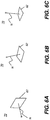
- Figures 6A, 6B, and 6C show icon 70 rotated to show three alternate viewing angles.
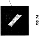
- Figure 7A shows cutting plane 62 at a given angle with respect to the display of a segmented tooth 40.
- Figures 7B and 7C show two of the many image slices 74 and 76, respectively, that are available at the view angle of this cutting plane.
- the wheel on the operator mouse is turned to quickly page through views of successive slices in a sequential manner.
- Other types of paging utility can alternately be used.
- Figures 8A and 8B show the use of an alternate cutting plane 62 for viewing image slices 78 from the same tooth at a different viewing angle.
- Operator interface utilities for changing the view angle, paging through slices according to the view angle, marking an image to indicate the tooth for segmentation, and other functions can use keyboard commands, on-screen menu instructions provided on a display, instructions selected from a menu, such as from a pull-down menu, instructions entered by selecting control buttons on the display screen, or instructions entered from some other source.
- Figures 9A , 9B , and 9C show different volume rendering views of a subject tooth that exhibits VRF.
- Embodiments of the present invention allow an operator to flexibly switch from one tooth to the next using the spline marking method described earlier with reference to Figure 3 .
- the operator can move to a different tooth by changing the position of spline 52, either by deleting and redrawing spline 52, or moving this graphic object onto another tooth.
- An embodiment of the present invention also allows the operator to specify more than one subject tooth at a time for segmentation.
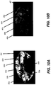
- image 72 having multiple sculpting splines 50a and 50b for indicating background content.
- the use of multiple sculpting splines can help to provide more information on background content to the segmentation algorithm.
- Splines 52a, 52b, 52c, 52d, 52e, and 52f then indicate individual subject teeth or clusters of adjacent teeth for segmentation.
- Figure 10B shows a resulting segmentation, with multiple corresponding subject teeth 40a, 40b, 40c, 40d, 40e, and 40f extracted from the volume image content and displayed.
- a cutting plane can also be used for adjusting the view angle for slices of the segmented structures.
- Embodiments of the present invention can be adapted to provide different 3-D visualization combinations of both volume rendering and surface rendering for a subject tooth, its internal structures, and its surrounding bone anatomy.
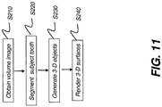
- the logic flow diagram of Figure 11 shows a sequence of steps used for surface rendering of the volume image data.
- a CBCT or other volume image containing the subject tooth is obtained.
- a segmentation step S220 follows, segmenting the subject tooth from the balance of the volume image data.
- a 3-D object generation step S230 then identifies features of interest from the volume image.
- a rendering step S240 then generates a 3-D surface rendering of the subject tooth and its related features of interest.
- Figures 12A, 12B, and 12C show results of surface rendering for subject tooth 40 having a root canal 80 and a fracture 82.
- Figure 12C is a wire frame view of tooth 40 from another view angle.
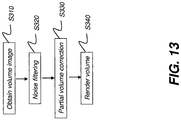
- FIG 13 is a logic flow diagram that shows a sequence of steps used for volume rendering according to an embodiment of the present invention.
- a CBCT or other volume image containing the subject tooth is obtained.
- An optional noise filtering step S320 provides noise filtering for the volume image data.
- An optional partial volume correction step S330 then corrects for partial volume effects. These imaging artifacts occur at tissue interfaces and can cause inaccuracy in both volume and surface rendering.
- One approach to partial volume correction is described, for example, in an article entitled " Volume Rendering in the Presence of Partial Volume Effects" by Andre Souza, Jayaram Udupa, and Punam Saha in IEEE Transactions on Medical Imaging, Vol. 24, No. 2, Feb. 2005, pp. 223-235 .
- a volume rendering step S340 is then executed, providing a rendered image of the subject tooth, such as the images shown in Figures 9A , 9B , and 9C , for example.
- an image foresting transform (IFT) is used, as described, for example, in the Falcao et al. article noted earlier.
- IFT image foresting transform
- Other types of image representation could alternately be used to represent the image and allow its manipulation.
- the present invention may be embodied as a system or method, with parts of the system executed using a computer program product, such as computer 106 shown in Figure 2 or other control logic processor device that is programmed with instructions for displaying an image, accepting operator instructions and input data, and responding to the operator entries.
- a computer program product such as computer 106 shown in Figure 2 or other control logic processor device that is programmed with instructions for displaying an image, accepting operator instructions and input data, and responding to the operator entries.
- an embodiment of the present invention may be in the form of an entirely hardware embodiment or an embodiment combining software and hardware aspects that may all generally be referred to herein as a "circuit" or "system.”
- parts of the present invention may take the form of a computer program product embodied in a computer-readable storage medium, with instructions executed by one or more computers or host processors.
- This medium may comprise, for example: magnetic storage media such as a magnetic disk (such as a hard drive or storage disk) or magnetic tape; optical storage media such as an optical disc, optical tape, or machine readable bar code; solid state electronic storage devices such as solid state hard drives, random access memory (RAM), or read only memory (ROM); or any other physical device or medium employed to store a computer program.
- the computer program for performing the method of the present invention may also be stored on computer readable storage medium that is connected to a host processor by way of the internet or other communication medium.
- memory can refer to any type of temporary or more enduring data storage workspace used for storing and operating upon image data and accessible to a computer system, including a database, for example.
- the memory could be non-volatile, using, for example, a long-term storage medium such as magnetic or optical storage. Alternately, the memory could be of a more volatile nature, using an electronic circuit, such as random-access memory (RAM) that is used as a temporary buffer or workspace by a microprocessor or other control logic processor device.
- Display data for example, is typically stored in a temporary storage buffer that is directly associated with a display device and is periodically refreshed as needed in order to provide displayed data.
- This temporary storage buffer can also be considered to be a memory, as the term is used in the present disclosure.
- Memory is also used as the data workspace for executing and storing intermediate and final results of calculations and other processing.
- Computer-accessible memory can be volatile, non-volatile, or a hybrid combination of volatile and non-volatile types.
- the computer-usable or computer-readable medium could even be paper or another suitable medium upon which executable instructions are printed, as the instructions can be electronically captured, via, for instance, optical scanning of the paper or other medium, then compiled, interpreted, or otherwise processed in a suitable manner, if necessary, and then stored in a computer memory.
- a computer-usable or computer-readable medium may be any medium that can contain, store, communicate, propagate, or transport computer instructions for use by, or in connection with, an instruction execution system, apparatus, or device.
Description
- The invention relates generally to dental imaging, and in particular to a radiographic imaging apparatus for viewing volume images of tooth structures.
- Cone beam computed tomography (CBCT) is an X-ray imaging modality capable of acquiring three-dimensional information of the human anatomy with a substantially lower radiation dose to the patient as compared to conventional medical computed tomography (CT) systems. Cone beam CT systems capture volumetric data sets by using a high frame rate digital radiography (DR) detector and an x-ray source, typically affixed to a gantry that rotates about the subject to be imaged, directing, from various points along its orbit around the subject, a divergent cone beam of x-rays toward the subject. The CBCT system captures projections throughout the rotation, for example, one 2-D projection image at every degree of rotation. The projections are then reconstructed into a 3D volume image using various techniques. Among the most common methods for reconstructing the 3-D volume image are filtered back projection approaches.
- One area of particular interest for CBCT use is in endodontics. In conventional practice, detection of a problem responsive to endodontic treatment begins with the patient's report of pain. The practitioner works with the patient to isolate the suspect tooth and may obtain one or more two-dimensional (2-D) periapical radiographs to help identify any abnormalities of the root structure and surrounding bone structure. In many cases, visual inspection of the 2-D image can help to identify the problem. However, detection of some types of conditions remains a challenge with conventional 2-D images. In particular, some types of Vertical root fracture (VRF) can be difficult to detect in the periapical image. Vertical root fracture is a severe type of tooth fracture that affects the root, causing pain due to infection and inflammation and often leading to tooth extraction.
- The improved image quality available from CBCT imaging and its capability for displaying very low contrast tissue regions makes CBCT a promising technology for assessment of VRF and other endodontic conditions. This includes use of CBCT imaging to support root canal therapy, as shown in the sequence of
Figure 1 . In this type of treatment, an infectedtooth 20 has anabscess 22 that is to be treated. Anopening 24 is made intooth 20 and atool 28 used to access and remove infected material. Aplugger 30 then fills root portions oftooth 20 with gutta percha or other suitable material. Thetooth 20 can then be repaired with afilling 34 or with acrown 36 that is fitted onto apost 38 inserted by the practitioner. - While CBCT imaging can be used to improve detection of VRF and other conditions requiring endodontic treatment, however, difficulties remain. Manipulating the CBCT image can be challenging, particularly for practitioners and technicians who are new to volume imaging technology. Isolating the particular views that most distinctly reveal the problem condition can be difficult or frustrating for the practitioner, burdening the user with a time commitment for training and using the CBCT- system.
- Further, reference is made to the following documents:
-
US 2008 030 497 A is directed to a method for segmentation of 3-D image sets to obtain digital models of objects identifiable in the image data set. -
US 2009 079 738 A describes a system and method for modifying a curved cut plane of a 3D volume to locate objects or sections of interest within the 3D volume intersected by the cut plane. - Falcao et al, INTERACTIVE VOLUME SEGMENTATION WITH DIFFERENTIAL IMAGE FORESTING TRANSFORMS", IEEE Transactions on Medical Imaging, Vol. 23, No. 9, September 2004, describes a general framework for interactive volume segmentation.
-
EP 1 470 784 A2 discloses an ultrasonic diagnostic apparatus including an optimum cross section setter which sets, as a four-cavity cross section, a cutting plane in which the cross sectional area of the four cavities becomes maximum. - An aspect of the present invention is to advance the art of dental imaging, particularly for volume imaging allowing interactive examination of teeth and their root structures. Advantageously, embodiments of the present invention allow an operator to select a specific tooth or group of teeth from volume image data and to modify the angle at which the tooth is viewed. In addition, the operator is also able to page through slices of the tooth from angles other than the standard coronal, sagittal, or axial images provided in conventional volume image presentation. Interactive operation allows the operator to progressively improve tooth segmentation used to isolate the data for a particular tooth from other volume image data.
- In accordance with the invention, a method as set forth in claim 1 is provided. Further embodiments of the invention are inter alia shown in the dependent claims. In particular, a method for 3-D interactive examination of a subject tooth is provided, wherein the method is executed at least in part by a computer and comprises: obtaining volume image data containing at least the subject tooth and background content adjacent to the subject tooth; displaying a first image from the volume data that shows at least the subject tooth and the background content; identifying a portion of the background content in the first image according to a first operator instruction; identifying tooth content for the at least the subject tooth in the first image according to a second operator instruction; segmenting the at least the subject tooth from within the volume data according to the first and second operator instructions; and displaying the segmented subject tooth.
- These objects are given only by way of illustrative example, and such objects may be exemplary of one or more embodiments of the invention. Other desirable objectives and advantages inherently achieved by the disclosed invention may occur or become apparent to those skilled in the art. The invention is defined by the appended claims.
- The foregoing and other objects, features, and advantages of the invention will be apparent from the following more particular description of the embodiments of the invention, as illustrated in the accompanying drawings. The elements of the drawings are not necessarily to scale relative to each other.
-
Figure 1 is a sequence diagram that shows steps for root canal therapy. -
Figure 2 is a schematic block diagram that shows components of a CBCT imaging apparatus for dental imaging. -
Figure 3A is a plan view that shows an image and markings that provide operator instructions for tooth segmentation. -
Figure 3B is a plan view showing a segmented tooth of interest from operator markup as provided inFigure 3A . -
Figure 3C is a logic flow diagram that shows operator interaction with the imaging system for obtaining a 3-D segmentation for a subject tooth. -
Figures 4A and4B are schematic views that show arrangement of slices at alternate angles for the same volume image content. -
Figures 5A and 5B show results and tools for an interactive utility that provides 3D visualization of abnormalities of the root structure and surrounding bone structure -
Figures 6A, 6B, and 6C show a view angle icon rotated to show entry of an instruction to view the data at three alternate viewing angles. -
Figure 7A shows a cutting plane position relative to a segmented tooth. -
Figure 7B shows a slice from the segmented tooth according to the cutting plane setting shown inFigure 7A . -
Figure 7C shows an alternate slice from the segmented tooth according to the cutting plane setting shown inFigure 7A . -
Figure 8A shows a cutting plane position relative to a segmented tooth. -
Figure 8B shows a slice from the segmented tooth according to the cutting plane setting shown inFigure 10A . -
Figures 9A ,9B , and9C show different volume rendering views of a subject tooth that exhibits VRF. -
Figure 10A shows a reference image having splines that indicate multiple teeth for segmentation. -
Figure 10B shows segmented teeth displayed for the multiple spline example ofFigure 10A . -
Figure 11 is a logic flow diagram that shows a sequence of steps used for surface rendering of a volume image. -
Figures 12A, 12B, and 12C are images that show results of surface rendering for a subject tooth having a root canal and a fracture. -
Figure 13 is a logic flow diagram that shows a sequence of steps used for volume rendering according to an embodiment of the present invention. - The following is a description of exemplary embodiments of the invention, reference being made to the drawings in which the same reference numerals identify the same elements of structure in each of the several figures. Where they are used, the terms "first", "second", and the like, do not necessarily denote any ordinal or priority relation, but may be used for more clearly distinguishing one element or time interval from another.
- In the context of the present disclosure, the term "image" refers to multi-dimensional image data that is composed of discrete image elements. For 2-D images, the discrete image elements are picture elements, or pixels. For 3-D images, also termed volume images, the discrete image elements are volume image elements, or voxels. In the context of the present disclosure, the term "spline" is equivalent to a curve, free-form curve, or line.
- As described by Falcao, et al. in the article entitled "The Image Foresting Transformation: Theory, Algorithm, and Applications," in IEEE Trans on Pattern Analysis and Machine Intelligence, 26 (1): 19-29, 2004), a multi-dimensional image can alternately be expressed as a set of nodes and arc-weights. By taking advantage of this alternate type of data structure, one can devise simple, effective and very fast (sub-linear) processing algorithm in the control processing unit (CPU) or graphics processing unit (GPU) for processing substantial amounts of image data. In the context of the present disclose, the term "IFT" refers to a framework that represents the image data as a set of nodes and arcs-weights, also known as the image foresting transform.
- In the context of the present invention, the terms "viewer", "user", and "operator" are considered to be equivalent terms for the person who uses the system and observes and manipulates the displayed view of the volume data for one or more of the patient's teeth. The operator can be a dental practitioner or technician or other person
- The term "highlighting" for a displayed feature has its conventional meaning as is understood to those skilled in the information and image display arts. In general, highlighting uses some form of localized display enhancement to attract the attention of the viewer. Highlighting a portion of an image, such as an individual organ, bone, or structure, or a path from one chamber to the next, for example, can be achieved in any of a number of ways, including, but not limited to, annotating, displaying a nearby or overlaying symbol, outlining or tracing, display in a different color or at a markedly different intensity or gray scale value than other image or information content, blinking or animation of a portion of a display, or display at higher sharpness or contrast.
- The schematic diagram of
Figure 2 shows animaging apparatus 100 for volume imaging, such as CBCT imaging, in which a succession of two or more 2-D images is obtained and images of adjacent content are processed to form a 3-D or volume image. Arotatable mount 130 is provided on acolumn 118 for imaging apatient 12.Mount 130 maintains anx-ray source 110 and aradiation sensor 121 on opposite sides of the head ofpatient 12 and rotates to orbitsource 110 andsensor 121 in a scan pattern about the head.Mount 130 rotates about an axis Q that corresponds to a central portion of the patient's head, so that its attached components orbit about the head.Sensor 121, a digital radiography sensor according to an embodiment of the present invention, is coupled to mount 130,opposite x-ray source 110 that emits a radiation pattern suitable for CBCT volume imaging. Anoptional head support 136, such as a chin rest or bite element, provides stabilization of the patient's head during image acquisition. Acomputer 106 has anoperator interface 104 and adisplay 108 for accepting operator commands and for display of volume images obtained byimaging apparatus 100.Computer 106, withmemory 132, is in signal communication withsensor 121 for obtaining image data and provides signals for control ofsource 110 and, optionally, for control of arotational actuator 112 formount 130 components. - Embodiments of the present invention process images obtained from
imaging apparatus 100 to provide a volume image that allows a practitioner to view teeth and supporting structures in detail. According to an embodiment of the present invention, the volume image data that is obtained fromimaging apparatus 100 enable the practitioner to view images of a tooth that can allow assessment of endodontic conditions that can be difficult to detect using conventional radiography images. -
Figure 3A shows a plan view of animage 72 obtained usingvolume imaging apparatus 100.Image 72 can be any slice of the image, as the image slice would appear on display 108 (Figure 2 ).Image 72 is used as a type of index image for markup.Figure 3A shows, withinimage 72 the tooth of interest, asubject tooth 40, that the practitioner would like to view in detail. One or more neighboring oradjacent teeth 42 may also be shown.Background content 44 is in the area outside ofteeth spline 50, indicates the location of tooth content forsubject tooth 40. A second operator instruction, a background or sculpting curve orspline 52 can be drawn onimage 72 outside the border of the subject tooth or within any suitable background area. - In the example of
Figure 3A ,spline 52 indicates picture elements that lie in thebackground content 44, such as in the area outside of or betweenteeth Tooth identifier spline 50 can span a single tooth in the displayedimage 72, or can span multiple teeth, as described in more detail subsequently. - According to an embodiment of the present invention, splines 50 and 52 are entered using a touch screen, that is, where display 108 (
Figure 2 ) associated with theimaging apparatus 100 is a touch screen device. In an alternate embodiment, another type of pointer device is used, such as a mouse, stylus, or joystick, for example. According to an embodiment of the present invention, splines of different colors are used to identify tooth content and differentiate the tooth content from background content for the segmentation algorithm.Splines -
Splines subject tooth 40 from the balance of the volume image data, in real time. A 3-D model ofsubject tooth 40 is displayed side-by-side with highlighted 2-D segmented regions in the slice image, as is shown in the example ofFigures 3A and 3B . According to an embodiment of the present invention, the subject tooth is highlighted on the display screen as verification to the operator. Highlighting can be indicated by change of color, heightened contrast, outlining, or some other display enhancement feature. - Following the tracing of one or more splines onto displayed
image 72, the operator enters a keyboard command or other instruction that initiates segmentation to extract the tooth volume from within the volume image data according to the entered splines. As shown inFigure 3B , at the completion of 3-D segmentation processing,subject tooth 40 displays ondisplay 108.Figure 3B shows a wireframe view; an operator instruction, such as a keyboard command, toggles between surface rendering and wireframe rendering. This view of the 2-D image slices oftooth 40 is provided at an initial view angle. This initial view angle may be one of the conventional sagittal, coronal, and axial view angles that are typically used as default view angles for CBCT data or may be a different view angle. According to an embodiment of the present invention, a 3-D cutting plane is generated automatically in response to the operator instruction and an IFT optimization routine finds a suitable viewing angle that maximizes the number of root canal- and fracture -like pixels in the slice images. This is an initial cutting plane for viewing and paging through slices in the volume image, where both the root canal and the root fracture (if present) are highlighted. A 3-D interactive examination phase is then initiated, as shown inFigure 5B , allowing the operator to change the cutting plane's normal vector N for any given oblique orientation. - The operator is in control of image manipulation. This allows the operator to quickly and confidently examine abnormalities, such as fractures in 3D, without worry about missing the selected tooth.
- According to an alternate embodiment of the present invention, control keys are provided to switch quickly between standard view angles. Zoom in/out utilities are also available, using a mouse or other pointer.
-
Figure 3C is a logic flow diagram that shows operator interaction with the imaging system for modeling and obtaining a 3-D segmentation for a subject tooth. In an object identification step S110, the operator positions one or more identifier splines over the subject tooth or portion of a tooth or other structure to be modeled. In a background identification step S120, the operator positions one or more background or sculpting splines for marking the background region. In response to operator entries in steps S110 and S120, the system generates and displays a coarse 3-D model in a model display step S130. In a looping step S140, the operator has the option to loop back through steps S110 and S120 as needed to refine and improve the results from the system that display in step S130. It is noted that steps S110 and S120 can be performed in any order and can be repeated as many times as needed, with entry of as many identifying and background splines as are useful for providing a suitable 3-D modeling of the subject tooth or other structure. According to an embodiment of the present invention, the color of a spline indicates its function, either as an indicator or background spline. Additionally, the color of an entered indicator spline determines color that is used for the generated 3-D model that displays. On-screen utilities and tools provided with the mouse or other pointer enable changing the color of an entered spline as desired. - The operator can add
additional splines subject tooth 40. This feature can help, for example, where the displayed segmentation appears to be inaccurate, such as where other teeth or tissue display with the segmentedsubject tooth 40. -
Figures 4A and4B show, in schematic form, how different views of the volume data fortooth 40 can be presented and show how a cuttingplane 62 can be defined and changed according to embodiments of the present invention. InFigure 4A , avolume image 58 has itsslices plane 62 having a normal N as shown.Figure 4B shows how the same volume image data can be rearranged along a different cutting plane 62' having a corresponding normal N', so that the image content ofvolume image 58 is formed byslices - With the volume image provided in this form, the same
subject tooth 40 can be viewed from alternate angles. Moreover, by paging throughslices subject tooth 40. As is shown inFigure 4A , afissure 66 is most readily visible onslice 60g, obtained at the viewing angle defined by cuttingplane 62. Other views oftooth 40 may not showfissure 66 or other anomaly in sufficient detail for assessment of the patient's condition. - It is noted that
Figures 4A and4B represent different views of the same volume data. The arrangement of voxel data into slices of the appropriate geometry is performed using volume image reconstruction techniques familiar to those skilled in the image processing arts. Paging through successive slices of the volume image can be performed in any of a number of ways, such as by pressing a keyboard key or combination of keys, using a mouse or pointer, or using other appropriate user interface utility. - The view of
Figure 5A shows aslice 60 obtained and displayed from an image of asubject tooth 40, whereslice 60 shows a root fracture, such as a VRF described earlier, or other endodontic complication. It can be appreciated that the problem with the tooth that is indicated inFigure 5A cannot be as readily perceived in a view taken from another angle. -
Figure 5A is a default view that is calculated by an algorithm that detects root canal and tooth fracture features in the image data. According to an embodiment of the present invention, this view automatically displays when aparticular tooth 40 is selected. This view is typically not a conventional axial, sagittal, or coronal view of the tooth; instead, the view angle is selected by the system for good visibility of root canal and fracture features. -
Figure 5B also shows avolume rendering 74, as described in an article by Souza et al., entitled "Volume rendering in the presence of partial volume effects," IEEE Trans on Medical Imaging, 24(2): 223-225, 2005). Thesubject tooth 40 is highlighted using awireframe surface rendering 72. A 3D user interaction utility for specifying the particular cuttingplane 62 is shown, as used for arranging the volume image data. Anangle selection icon 70 shows a cuttingplane 62 and normal N in representational form, for manipulation by the operator. Using a mouse, touch screen, or other pointing mechanism, the operator can change the orientation of normal N andplane 62 oficon 70, thereby providing a plane angle instruction for modifying the angle at which the volume image data is presented. By way of example,Figures 6A, 6B, and 6C show icon 70 rotated to show three alternate viewing angles. - By way of example,
Figure 7A shows cuttingplane 62 at a given angle with respect to the display of asegmented tooth 40.Figures 7B and 7C show two of the many image slices 74 and 76, respectively, that are available at the view angle of this cutting plane. According to an embodiment of the present invention, the wheel on the operator mouse is turned to quickly page through views of successive slices in a sequential manner. Other types of paging utility can alternately be used.Figures 8A and 8B show the use of analternate cutting plane 62 for viewing image slices 78 from the same tooth at a different viewing angle. - Operator interface utilities for changing the view angle, paging through slices according to the view angle, marking an image to indicate the tooth for segmentation, and other functions can use keyboard commands, on-screen menu instructions provided on a display, instructions selected from a menu, such as from a pull-down menu, instructions entered by selecting control buttons on the display screen, or instructions entered from some other source.
-
Figures 9A ,9B , and9C show different volume rendering views of a subject tooth that exhibits VRF. - Embodiments of the present invention allow an operator to flexibly switch from one tooth to the next using the spline marking method described earlier with reference to
Figure 3 . The operator can move to a different tooth by changing the position ofspline 52, either by deleting and redrawingspline 52, or moving this graphic object onto another tooth. - An embodiment of the present invention also allows the operator to specify more than one subject tooth at a time for segmentation. Referring to
Figure 10A , there is shownimage 72 havingmultiple sculpting splines Splines Figure 10B shows a resulting segmentation, with multiple correspondingsubject teeth splines - Embodiments of the present invention can be adapted to provide different 3-D visualization combinations of both volume rendering and surface rendering for a subject tooth, its internal structures, and its surrounding bone anatomy. The logic flow diagram of
Figure 11 shows a sequence of steps used for surface rendering of the volume image data. In an obtain volume step S210, a CBCT or other volume image containing the subject tooth is obtained. A segmentation step S220 follows, segmenting the subject tooth from the balance of the volume image data. A 3-D object generation step S230 then identifies features of interest from the volume image. A rendering step S240 then generates a 3-D surface rendering of the subject tooth and its related features of interest. -
Figures 12A, 12B, and 12C show results of surface rendering forsubject tooth 40 having aroot canal 80 and afracture 82.Figure 12C is a wire frame view oftooth 40 from another view angle. -
Figure 13 is a logic flow diagram that shows a sequence of steps used for volume rendering according to an embodiment of the present invention. In an obtain volume step S310, a CBCT or other volume image containing the subject tooth is obtained. An optional noise filtering step S320 provides noise filtering for the volume image data. An optional partial volume correction step S330 then corrects for partial volume effects. These imaging artifacts occur at tissue interfaces and can cause inaccuracy in both volume and surface rendering. One approach to partial volume correction is described, for example, in an article entitled "Volume Rendering in the Presence of Partial Volume Effects" by Andre Souza, Jayaram Udupa, and Punam Saha in IEEE Transactions on Medical Imaging, Vol. 24, No. 2, Feb. 2005, pp. 223-235. A volume rendering step S340 is then executed, providing a rendered image of the subject tooth, such as the images shown inFigures 9A ,9B , and9C , for example. - A number of different types of structure identification and image segmentation algorithms could be employed for providing segmentation according to entered operator instructions. According to an embodiment of the present invention, an image foresting transform (IFT) is used, as described, for example, in the Falcao et al. article noted earlier. Other types of image representation could alternately be used to represent the image and allow its manipulation.
- As will be appreciated by one skilled in the art, the present invention may be embodied as a system or method, with parts of the system executed using a computer program product, such as
computer 106 shown inFigure 2 or other control logic processor device that is programmed with instructions for displaying an image, accepting operator instructions and input data, and responding to the operator entries. Accordingly, an embodiment of the present invention may be in the form of an entirely hardware embodiment or an embodiment combining software and hardware aspects that may all generally be referred to herein as a "circuit" or "system." Furthermore, parts of the present invention may take the form of a computer program product embodied in a computer-readable storage medium, with instructions executed by one or more computers or host processors. This medium may comprise, for example: magnetic storage media such as a magnetic disk (such as a hard drive or storage disk) or magnetic tape; optical storage media such as an optical disc, optical tape, or machine readable bar code; solid state electronic storage devices such as solid state hard drives, random access memory (RAM), or read only memory (ROM); or any other physical device or medium employed to store a computer program. The computer program for performing the method of the present invention may also be stored on computer readable storage medium that is connected to a host processor by way of the internet or other communication medium. - It is noted that the term "memory", equivalent to "computer-accessible memory" in the context of the present disclosure, can refer to any type of temporary or more enduring data storage workspace used for storing and operating upon image data and accessible to a computer system, including a database, for example. The memory could be non-volatile, using, for example, a long-term storage medium such as magnetic or optical storage. Alternately, the memory could be of a more volatile nature, using an electronic circuit, such as random-access memory (RAM) that is used as a temporary buffer or workspace by a microprocessor or other control logic processor device. Display data, for example, is typically stored in a temporary storage buffer that is directly associated with a display device and is periodically refreshed as needed in order to provide displayed data. This temporary storage buffer can also be considered to be a memory, as the term is used in the present disclosure. Memory is also used as the data workspace for executing and storing intermediate and final results of calculations and other processing. Computer-accessible memory can be volatile, non-volatile, or a hybrid combination of volatile and non-volatile types.
- Those skilled in the art will readily recognize that the equivalent of such a computer program product may also be constructed in hardware. The computer-usable or computer-readable medium could even be paper or another suitable medium upon which executable instructions are printed, as the instructions can be electronically captured, via, for instance, optical scanning of the paper or other medium, then compiled, interpreted, or otherwise processed in a suitable manner, if necessary, and then stored in a computer memory. In the context of this document, a computer-usable or computer-readable medium may be any medium that can contain, store, communicate, propagate, or transport computer instructions for use by, or in connection with, an instruction execution system, apparatus, or device.
Claims (10)
- A method for 3-D interactive examination of a subject tooth (40), the method executed at least in part by a computer, comprising:obtaining (S210) CBCT volume image data (58) containing at least the subject tooth (40) and background content (44) adjacent to the subject tooth (40);displaying a first image from the CBCT volume image data (58) that shows at least the subject tooth (40) and the background content (44);identifying a portion of the background content (44) in the first image according to a first operator instruction;identifying tooth content for the at least the subject tooth (40) in the first image according to a second operator instruction;segmenting (S220) the at least the subject tooth (40) including a root canal volume from within the CBCT volume image data (58) according to the first and second operator instructions;automatically computing a cutting plane (62, 62') for viewing slice images of the tooth (40) that show both of root canal-like pixels and tooth fracture-like pixels, said cutting plane (62, 62') having a viewing angle that maximizes the number of root canal-like and fracture-like pixels in the slice images anddisplaying the segmented subject tooth (40) according to the computed cutting plane (62, 62').
- The method of claim 1 further comprising changing the display of the segmented subject tooth (40) within the CBCT volume image data (58) according to a paging instruction from an operator.
- The method of claim 1 further comprising changing a relative angle of the cutting plane (62, 62') in response to a plane angle adjustment instruction from an operator.
- The method of claim 1 further comprising forming a reduced-resolution copy of the CBCT volume image data (58) prior to segmenting the subject tooth (40).
- The method of claim 1 further comprising correcting for partial volume effects in the CBCT volume image data (58).
- The method of claim 1 further comprising defining the first operator instruction by drawing (S110) a spline on the displayed first image.
- The method of claim 1 further comprising defining the second operator instruction by drawing (S120) a spline over two or more teeth on the displayed first image.
- The method of claim 1 wherein the subject tooth (40) is a first subject tooth (40) and further comprising accepting a third operator instruction that indicates location of tooth content for a second subject tooth (42) in the first image.
- The method of claim 1 further comprising automatically highlighting root canal pixels or fracture-like pixels in the displayed segmented subject tooth (40).
- The method of claim 1 wherein displaying the segmented subject tooth (40) comprises rendering (S240) a surface image of the subject tooth (40).
Applications Claiming Priority (1)
| Application Number | Priority Date | Filing Date | Title |
|---|---|---|---|
| US13/422,145 US8923581B2 (en) | 2012-03-16 | 2012-03-16 | Interactive 3-D examination of root fractures |
Publications (2)
| Publication Number | Publication Date |
|---|---|
| EP2639764A1 EP2639764A1 (en) | 2013-09-18 |
| EP2639764B1 true EP2639764B1 (en) | 2019-04-17 |
Family
ID=47844041
Family Applications (1)
| Application Number | Title | Priority Date | Filing Date |
|---|---|---|---|
| EP13001119.0A Active EP2639764B1 (en) | 2012-03-16 | 2013-03-06 | Interactive 3-D examination of root fractures |
Country Status (4)
| Country | Link |
|---|---|
| US (1) | US8923581B2 (en) |
| EP (1) | EP2639764B1 (en) |
| JP (1) | JP6205146B2 (en) |
| KR (1) | KR20130105519A (en) |
Families Citing this family (15)
| Publication number | Priority date | Publication date | Assignee | Title |
|---|---|---|---|---|
| EP2688479B1 (en) * | 2011-03-21 | 2018-08-29 | Carestream Dental Technology Topco Limited | A method for tooth surface classification |
| US20140195030A1 (en) * | 2013-01-08 | 2014-07-10 | Warsaw Orthopedic, Inc. | Cutting decision-making system and method for donated tissues |
| JP5744084B2 (en) * | 2013-03-06 | 2015-07-01 | 株式会社モリタ製作所 | Dental image display device, dental treatment device, and method of operating dental image display device |
| US9855114B2 (en) * | 2013-05-21 | 2018-01-02 | Carestream Health, Inc. | Method and system for user interaction in 3-D cephalometric analysis |
| US9947129B2 (en) * | 2014-03-26 | 2018-04-17 | Carestream Health, Inc. | Method for enhanced display of image slices from 3-D volume image |
| KR20180090308A (en) | 2015-12-04 | 2018-08-10 | 쓰리세이프 에이/에스 | Deriving tooth status information for populating digital dental charts |
| CN106228549B (en) * | 2016-07-14 | 2019-04-19 | 嘉兴学院 | A kind of triangle gridding tooth dividing method based on path planning |
| WO2018033762A1 (en) * | 2016-08-15 | 2018-02-22 | Trophy | Dynamic dental arch map |
| WO2019147868A1 (en) * | 2018-01-26 | 2019-08-01 | Align Technology, Inc. | Visual prosthetic and orthodontic treatment planning |
| US10977837B2 (en) * | 2018-06-21 | 2021-04-13 | Canon Medical Systems Corporation | Medical image processing apparatus and method |
| US11389131B2 (en) | 2018-06-27 | 2022-07-19 | Denti.Ai Technology Inc. | Systems and methods for processing of dental images |
| KR102132369B1 (en) * | 2018-08-23 | 2020-07-09 | 주식회사 쓰리디산업영상 | Tooth segmentation system and method |
| CN109146867B (en) * | 2018-08-24 | 2021-11-19 | 四川智动木牛智能科技有限公司 | Oral cavity curved surface CT image biological feature extraction and matching method and device |
| US11222435B2 (en) * | 2019-11-11 | 2022-01-11 | James R. Glidewell Dental Ceramics, Inc. | Determining rotation axis from x-ray radiographs |
| US11585766B2 (en) | 2020-05-29 | 2023-02-21 | James R. Glidewell Dental Ceramics, Inc. | CT scanner calibration |
Citations (1)
| Publication number | Priority date | Publication date | Assignee | Title |
|---|---|---|---|---|
| EP1470784A2 (en) * | 2003-04-21 | 2004-10-27 | Aloka Co., Ltd. | Ultrasonic diagnostic apparatus |
Family Cites Families (8)
| Publication number | Priority date | Publication date | Assignee | Title |
|---|---|---|---|---|
| US6632089B2 (en) * | 1999-11-30 | 2003-10-14 | Orametrix, Inc. | Orthodontic treatment planning with user-specified simulation of tooth movement |
| DE10196737T1 (en) * | 2000-10-04 | 2003-09-04 | Nihon University Tokio Tokyo | Display method and device for an x-ray projection image for medical purposes, x-ray CT device for medical purposes and storage medium for storing a program for executing the display method |
| US20080030497A1 (en) | 2005-12-08 | 2008-02-07 | Yangqiu Hu | Three dimensional modeling of objects |
| US7978191B2 (en) | 2007-09-24 | 2011-07-12 | Dolphin Imaging Systems, Llc | System and method for locating anatomies of interest in a 3D volume |
| JP5337472B2 (en) * | 2008-12-24 | 2013-11-06 | イマグノーシス株式会社 | Method for displaying cut surface image in medical three-dimensional image, medical three-dimensional image display device, and medical image display program |
| JP2010246883A (en) * | 2009-03-27 | 2010-11-04 | Mitsubishi Electric Corp | Patient positioning system |
| US8244028B2 (en) * | 2010-04-30 | 2012-08-14 | Align Technology, Inc. | Virtual cephalometric imaging |
| US8970581B2 (en) * | 2012-01-04 | 2015-03-03 | Carestream Health, Inc. | System and method for interactive contouring for 3D medical images |
-
2012
- 2012-03-16 US US13/422,145 patent/US8923581B2/en not_active Expired - Fee Related
-
2013
- 2013-03-06 EP EP13001119.0A patent/EP2639764B1/en active Active
- 2013-03-14 KR KR1020130027453A patent/KR20130105519A/en active IP Right Grant
- 2013-03-15 JP JP2013053041A patent/JP6205146B2/en not_active Expired - Fee Related
Patent Citations (1)
| Publication number | Priority date | Publication date | Assignee | Title |
|---|---|---|---|---|
| EP1470784A2 (en) * | 2003-04-21 | 2004-10-27 | Aloka Co., Ltd. | Ultrasonic diagnostic apparatus |
Also Published As
| Publication number | Publication date |
|---|---|
| US20130243276A1 (en) | 2013-09-19 |
| JP2013192939A (en) | 2013-09-30 |
| US8923581B2 (en) | 2014-12-30 |
| EP2639764A1 (en) | 2013-09-18 |
| KR20130105519A (en) | 2013-09-25 |
| JP6205146B2 (en) | 2017-09-27 |
Similar Documents
| Publication | Publication Date | Title |
|---|---|---|
| EP2639764B1 (en) | Interactive 3-D examination of root fractures | |
| US9972083B2 (en) | Detection of tooth fractures in CBCT image | |
| US20230301611A1 (en) | Dental panoramic views | |
| JP5775244B2 (en) | System and method for 3D graphical prescription of medical imaging volume | |
| JP2009034503A (en) | Method and system for displaying tomosynthesis image | |
| EP2734116B1 (en) | Method for tooth dissection in cbct volume | |
| US11045290B2 (en) | Dynamic dental arch map | |
| US9361726B2 (en) | Medical image diagnostic apparatus, medical image processing apparatus, and methods therefor | |
| US20090003668A1 (en) | Image processing method, image processing program, and image processing device | |
| JP2014050695A (en) | Imaging apparatus for display of maxillary and mandibular arches | |
| US11900526B2 (en) | Volume rendering using surface guided cropping | |
| JP4806429B2 (en) | Digital panorama photographing apparatus and panorama image processing program | |
| JP7152738B2 (en) | Image processing device and image processing program | |
| KR102344521B1 (en) | Method for establishing diagnosis and treatment plan and 3D dental image providing device therefor | |
| JP2001101450A (en) | Three-dimensional image display device | |
| JP2001101449A (en) | Three-dimensional image display device | |
| JP6393538B2 (en) | Medical image processing apparatus, medical image processing system, medical image processing method, and medical image processing program | |
| JP6373937B2 (en) | X-ray CT apparatus and image display apparatus | |
| Suebnukarn et al. | Interactive segmentation and three-dimension reconstruction for cone-beam computed-tomography images | |
| JP6424147B2 (en) | Image processing apparatus, method, and program | |
| WO2018055426A1 (en) | Image acquisition in darkroom mode |
Legal Events
| Date | Code | Title | Description |
|---|---|---|---|
| PUAI | Public reference made under article 153(3) epc to a published international application that has entered the european phase |
Free format text: ORIGINAL CODE: 0009012 |
|
| AK | Designated contracting states |
Kind code of ref document: A1 Designated state(s): AL AT BE BG CH CY CZ DE DK EE ES FI FR GB GR HR HU IE IS IT LI LT LU LV MC MK MT NL NO PL PT RO RS SE SI SK SM TR |
|
| AX | Request for extension of the european patent |
Extension state: BA ME |
|
| 17P | Request for examination filed |
Effective date: 20140318 |
|
| RBV | Designated contracting states (corrected) |
Designated state(s): AL AT BE BG CH CY CZ DE DK EE ES FI FR GB GR HR HU IE IS IT LI LT LU LV MC MK MT NL NO PL PT RO RS SE SI SK SM TR |
|
| 17Q | First examination report despatched |
Effective date: 20160105 |
|
| RAP1 | Party data changed (applicant data changed or rights of an application transferred) |
Owner name: CARESTREAM DENTAL TECHNOLOGY TOPCO LIMITED |
|
| REG | Reference to a national code |
Ref country code: DE Ref legal event code: R079 Ref document number: 602013053915 Country of ref document: DE Free format text: PREVIOUS MAIN CLASS: G06T0007000000 Ipc: G06T0007110000 |
|
| GRAP | Despatch of communication of intention to grant a patent |
Free format text: ORIGINAL CODE: EPIDOSNIGR1 |
|
| STAA | Information on the status of an ep patent application or granted ep patent |
Free format text: STATUS: GRANT OF PATENT IS INTENDED |
|
| RIC1 | Information provided on ipc code assigned before grant |
Ipc: G06T 7/194 20170101ALI20180913BHEP Ipc: G06T 7/162 20170101ALI20180913BHEP Ipc: G06T 7/11 20170101AFI20180913BHEP |
|
| INTG | Intention to grant announced |
Effective date: 20181002 |
|
| GRAS | Grant fee paid |
Free format text: ORIGINAL CODE: EPIDOSNIGR3 |
|
| GRAA | (expected) grant |
Free format text: ORIGINAL CODE: 0009210 |
|
| STAA | Information on the status of an ep patent application or granted ep patent |
Free format text: STATUS: THE PATENT HAS BEEN GRANTED |
|
| AK | Designated contracting states |
Kind code of ref document: B1 Designated state(s): AL AT BE BG CH CY CZ DE DK EE ES FI FR GB GR HR HU IE IS IT LI LT LU LV MC MK MT NL NO PL PT RO RS SE SI SK SM TR |
|
| REG | Reference to a national code |
Ref country code: GB Ref legal event code: FG4D |
|
| REG | Reference to a national code |
Ref country code: CH Ref legal event code: EP |
|
| REG | Reference to a national code |
Ref country code: DE Ref legal event code: R096 Ref document number: 602013053915 Country of ref document: DE |
|
| REG | Reference to a national code |
Ref country code: AT Ref legal event code: REF Ref document number: 1122395 Country of ref document: AT Kind code of ref document: T Effective date: 20190515 Ref country code: IE Ref legal event code: FG4D |
|
| REG | Reference to a national code |
Ref country code: NL Ref legal event code: MP Effective date: 20190417 |
|
| REG | Reference to a national code |
Ref country code: LT Ref legal event code: MG4D |
|
| PG25 | Lapsed in a contracting state [announced via postgrant information from national office to epo] |
Ref country code: NL Free format text: LAPSE BECAUSE OF FAILURE TO SUBMIT A TRANSLATION OF THE DESCRIPTION OR TO PAY THE FEE WITHIN THE PRESCRIBED TIME-LIMIT Effective date: 20190417 |
|
| PG25 | Lapsed in a contracting state [announced via postgrant information from national office to epo] |
Ref country code: FI Free format text: LAPSE BECAUSE OF FAILURE TO SUBMIT A TRANSLATION OF THE DESCRIPTION OR TO PAY THE FEE WITHIN THE PRESCRIBED TIME-LIMIT Effective date: 20190417 Ref country code: PT Free format text: LAPSE BECAUSE OF FAILURE TO SUBMIT A TRANSLATION OF THE DESCRIPTION OR TO PAY THE FEE WITHIN THE PRESCRIBED TIME-LIMIT Effective date: 20190817 Ref country code: NO Free format text: LAPSE BECAUSE OF FAILURE TO SUBMIT A TRANSLATION OF THE DESCRIPTION OR TO PAY THE FEE WITHIN THE PRESCRIBED TIME-LIMIT Effective date: 20190717 Ref country code: AL Free format text: LAPSE BECAUSE OF FAILURE TO SUBMIT A TRANSLATION OF THE DESCRIPTION OR TO PAY THE FEE WITHIN THE PRESCRIBED TIME-LIMIT Effective date: 20190417 Ref country code: HR Free format text: LAPSE BECAUSE OF FAILURE TO SUBMIT A TRANSLATION OF THE DESCRIPTION OR TO PAY THE FEE WITHIN THE PRESCRIBED TIME-LIMIT Effective date: 20190417 Ref country code: SE Free format text: LAPSE BECAUSE OF FAILURE TO SUBMIT A TRANSLATION OF THE DESCRIPTION OR TO PAY THE FEE WITHIN THE PRESCRIBED TIME-LIMIT Effective date: 20190417 Ref country code: LT Free format text: LAPSE BECAUSE OF FAILURE TO SUBMIT A TRANSLATION OF THE DESCRIPTION OR TO PAY THE FEE WITHIN THE PRESCRIBED TIME-LIMIT Effective date: 20190417 Ref country code: ES Free format text: LAPSE BECAUSE OF FAILURE TO SUBMIT A TRANSLATION OF THE DESCRIPTION OR TO PAY THE FEE WITHIN THE PRESCRIBED TIME-LIMIT Effective date: 20190417 |
|
| PG25 | Lapsed in a contracting state [announced via postgrant information from national office to epo] |
Ref country code: RS Free format text: LAPSE BECAUSE OF FAILURE TO SUBMIT A TRANSLATION OF THE DESCRIPTION OR TO PAY THE FEE WITHIN THE PRESCRIBED TIME-LIMIT Effective date: 20190417 Ref country code: BG Free format text: LAPSE BECAUSE OF FAILURE TO SUBMIT A TRANSLATION OF THE DESCRIPTION OR TO PAY THE FEE WITHIN THE PRESCRIBED TIME-LIMIT Effective date: 20190717 Ref country code: PL Free format text: LAPSE BECAUSE OF FAILURE TO SUBMIT A TRANSLATION OF THE DESCRIPTION OR TO PAY THE FEE WITHIN THE PRESCRIBED TIME-LIMIT Effective date: 20190417 Ref country code: GR Free format text: LAPSE BECAUSE OF FAILURE TO SUBMIT A TRANSLATION OF THE DESCRIPTION OR TO PAY THE FEE WITHIN THE PRESCRIBED TIME-LIMIT Effective date: 20190718 Ref country code: LV Free format text: LAPSE BECAUSE OF FAILURE TO SUBMIT A TRANSLATION OF THE DESCRIPTION OR TO PAY THE FEE WITHIN THE PRESCRIBED TIME-LIMIT Effective date: 20190417 |
|
| REG | Reference to a national code |
Ref country code: AT Ref legal event code: MK05 Ref document number: 1122395 Country of ref document: AT Kind code of ref document: T Effective date: 20190417 |
|
| PG25 | Lapsed in a contracting state [announced via postgrant information from national office to epo] |
Ref country code: IS Free format text: LAPSE BECAUSE OF FAILURE TO SUBMIT A TRANSLATION OF THE DESCRIPTION OR TO PAY THE FEE WITHIN THE PRESCRIBED TIME-LIMIT Effective date: 20190817 |
|
| REG | Reference to a national code |
Ref country code: DE Ref legal event code: R097 Ref document number: 602013053915 Country of ref document: DE |
|
| PG25 | Lapsed in a contracting state [announced via postgrant information from national office to epo] |
Ref country code: CZ Free format text: LAPSE BECAUSE OF FAILURE TO SUBMIT A TRANSLATION OF THE DESCRIPTION OR TO PAY THE FEE WITHIN THE PRESCRIBED TIME-LIMIT Effective date: 20190417 Ref country code: RO Free format text: LAPSE BECAUSE OF FAILURE TO SUBMIT A TRANSLATION OF THE DESCRIPTION OR TO PAY THE FEE WITHIN THE PRESCRIBED TIME-LIMIT Effective date: 20190417 Ref country code: DK Free format text: LAPSE BECAUSE OF FAILURE TO SUBMIT A TRANSLATION OF THE DESCRIPTION OR TO PAY THE FEE WITHIN THE PRESCRIBED TIME-LIMIT Effective date: 20190417 Ref country code: AT Free format text: LAPSE BECAUSE OF FAILURE TO SUBMIT A TRANSLATION OF THE DESCRIPTION OR TO PAY THE FEE WITHIN THE PRESCRIBED TIME-LIMIT Effective date: 20190417 Ref country code: EE Free format text: LAPSE BECAUSE OF FAILURE TO SUBMIT A TRANSLATION OF THE DESCRIPTION OR TO PAY THE FEE WITHIN THE PRESCRIBED TIME-LIMIT Effective date: 20190417 Ref country code: SK Free format text: LAPSE BECAUSE OF FAILURE TO SUBMIT A TRANSLATION OF THE DESCRIPTION OR TO PAY THE FEE WITHIN THE PRESCRIBED TIME-LIMIT Effective date: 20190417 |
|
| PLBE | No opposition filed within time limit |
Free format text: ORIGINAL CODE: 0009261 |
|
| STAA | Information on the status of an ep patent application or granted ep patent |
Free format text: STATUS: NO OPPOSITION FILED WITHIN TIME LIMIT |
|
| PG25 | Lapsed in a contracting state [announced via postgrant information from national office to epo] |
Ref country code: IT Free format text: LAPSE BECAUSE OF FAILURE TO SUBMIT A TRANSLATION OF THE DESCRIPTION OR TO PAY THE FEE WITHIN THE PRESCRIBED TIME-LIMIT Effective date: 20190417 Ref country code: SM Free format text: LAPSE BECAUSE OF FAILURE TO SUBMIT A TRANSLATION OF THE DESCRIPTION OR TO PAY THE FEE WITHIN THE PRESCRIBED TIME-LIMIT Effective date: 20190417 |
|
| 26N | No opposition filed |
Effective date: 20200120 |
|
| PG25 | Lapsed in a contracting state [announced via postgrant information from national office to epo] |
Ref country code: TR Free format text: LAPSE BECAUSE OF FAILURE TO SUBMIT A TRANSLATION OF THE DESCRIPTION OR TO PAY THE FEE WITHIN THE PRESCRIBED TIME-LIMIT Effective date: 20190417 |
|
| PGFP | Annual fee paid to national office [announced via postgrant information from national office to epo] |
Ref country code: GB Payment date: 20200228 Year of fee payment: 8 Ref country code: DE Payment date: 20200214 Year of fee payment: 8 |
|
| PG25 | Lapsed in a contracting state [announced via postgrant information from national office to epo] |
Ref country code: SI Free format text: LAPSE BECAUSE OF FAILURE TO SUBMIT A TRANSLATION OF THE DESCRIPTION OR TO PAY THE FEE WITHIN THE PRESCRIBED TIME-LIMIT Effective date: 20190417 |
|
| PGFP | Annual fee paid to national office [announced via postgrant information from national office to epo] |
Ref country code: FR Payment date: 20200219 Year of fee payment: 8 |
|
| PG25 | Lapsed in a contracting state [announced via postgrant information from national office to epo] |
Ref country code: MC Free format text: LAPSE BECAUSE OF FAILURE TO SUBMIT A TRANSLATION OF THE DESCRIPTION OR TO PAY THE FEE WITHIN THE PRESCRIBED TIME-LIMIT Effective date: 20190417 |
|
| REG | Reference to a national code |
Ref country code: CH Ref legal event code: PL |
|
| REG | Reference to a national code |
Ref country code: BE Ref legal event code: MM Effective date: 20200331 |
|
| PG25 | Lapsed in a contracting state [announced via postgrant information from national office to epo] |
Ref country code: LU Free format text: LAPSE BECAUSE OF NON-PAYMENT OF DUE FEES Effective date: 20200306 |
|
| PG25 | Lapsed in a contracting state [announced via postgrant information from national office to epo] |
Ref country code: CH Free format text: LAPSE BECAUSE OF NON-PAYMENT OF DUE FEES Effective date: 20200331 Ref country code: IE Free format text: LAPSE BECAUSE OF NON-PAYMENT OF DUE FEES Effective date: 20200306 Ref country code: LI Free format text: LAPSE BECAUSE OF NON-PAYMENT OF DUE FEES Effective date: 20200331 |
|
| PG25 | Lapsed in a contracting state [announced via postgrant information from national office to epo] |
Ref country code: BE Free format text: LAPSE BECAUSE OF NON-PAYMENT OF DUE FEES Effective date: 20200331 |
|
| REG | Reference to a national code |
Ref country code: DE Ref legal event code: R119 Ref document number: 602013053915 Country of ref document: DE |
|
| GBPC | Gb: european patent ceased through non-payment of renewal fee |
Effective date: 20210306 |
|
| PG25 | Lapsed in a contracting state [announced via postgrant information from national office to epo] |
Ref country code: DE Free format text: LAPSE BECAUSE OF NON-PAYMENT OF DUE FEES Effective date: 20211001 Ref country code: FR Free format text: LAPSE BECAUSE OF NON-PAYMENT OF DUE FEES Effective date: 20210331 Ref country code: GB Free format text: LAPSE BECAUSE OF NON-PAYMENT OF DUE FEES Effective date: 20210306 |
|
| PG25 | Lapsed in a contracting state [announced via postgrant information from national office to epo] |
Ref country code: MT Free format text: LAPSE BECAUSE OF FAILURE TO SUBMIT A TRANSLATION OF THE DESCRIPTION OR TO PAY THE FEE WITHIN THE PRESCRIBED TIME-LIMIT Effective date: 20190417 Ref country code: CY Free format text: LAPSE BECAUSE OF FAILURE TO SUBMIT A TRANSLATION OF THE DESCRIPTION OR TO PAY THE FEE WITHIN THE PRESCRIBED TIME-LIMIT Effective date: 20190417 |
|
| PG25 | Lapsed in a contracting state [announced via postgrant information from national office to epo] |
Ref country code: MK Free format text: LAPSE BECAUSE OF FAILURE TO SUBMIT A TRANSLATION OF THE DESCRIPTION OR TO PAY THE FEE WITHIN THE PRESCRIBED TIME-LIMIT Effective date: 20190417 |