EP1470784A2 - Ultrasonic diagnostic apparatus - Google Patents
Ultrasonic diagnostic apparatus Download PDFInfo
- Publication number
- EP1470784A2 EP1470784A2 EP04002558A EP04002558A EP1470784A2 EP 1470784 A2 EP1470784 A2 EP 1470784A2 EP 04002558 A EP04002558 A EP 04002558A EP 04002558 A EP04002558 A EP 04002558A EP 1470784 A2 EP1470784 A2 EP 1470784A2
- Authority
- EP
- European Patent Office
- Prior art keywords
- section
- cross
- cavity
- basis
- left ventricle
- Prior art date
- Legal status (The legal status is an assumption and is not a legal conclusion. Google has not performed a legal analysis and makes no representation as to the accuracy of the status listed.)
- Granted
Links
Images
Classifications
-
- G—PHYSICS
- G06—COMPUTING OR CALCULATING; COUNTING
- G06T—IMAGE DATA PROCESSING OR GENERATION, IN GENERAL
- G06T19/00—Manipulating three-dimensional [3D] models or images for computer graphics
-
- A—HUMAN NECESSITIES
- A61—MEDICAL OR VETERINARY SCIENCE; HYGIENE
- A61B—DIAGNOSIS; SURGERY; IDENTIFICATION
- A61B8/00—Diagnosis using ultrasonic, sonic or infrasonic waves
- A61B8/08—Clinical applications
-
- A—HUMAN NECESSITIES
- A61—MEDICAL OR VETERINARY SCIENCE; HYGIENE
- A61B—DIAGNOSIS; SURGERY; IDENTIFICATION
- A61B8/00—Diagnosis using ultrasonic, sonic or infrasonic waves
- A61B8/08—Clinical applications
- A61B8/0883—Clinical applications for diagnosis of the heart
-
- A—HUMAN NECESSITIES
- A61—MEDICAL OR VETERINARY SCIENCE; HYGIENE
- A61B—DIAGNOSIS; SURGERY; IDENTIFICATION
- A61B8/00—Diagnosis using ultrasonic, sonic or infrasonic waves
- A61B8/48—Diagnostic techniques
- A61B8/483—Diagnostic techniques involving the acquisition of a 3D volume of data
-
- G—PHYSICS
- G01—MEASURING; TESTING
- G01S—RADIO DIRECTION-FINDING; RADIO NAVIGATION; DETERMINING DISTANCE OR VELOCITY BY USE OF RADIO WAVES; LOCATING OR PRESENCE-DETECTING BY USE OF THE REFLECTION OR RERADIATION OF RADIO WAVES; ANALOGOUS ARRANGEMENTS USING OTHER WAVES
- G01S7/00—Details of systems according to groups G01S13/00, G01S15/00, G01S17/00
- G01S7/52—Details of systems according to groups G01S13/00, G01S15/00, G01S17/00 of systems according to group G01S15/00
- G01S7/52017—Details of systems according to groups G01S13/00, G01S15/00, G01S17/00 of systems according to group G01S15/00 particularly adapted to short-range imaging
- G01S7/52053—Display arrangements
- G01S7/52057—Cathode ray tube displays
- G01S7/52073—Production of cursor lines, markers or indicia by electronic means
-
- G—PHYSICS
- G01—MEASURING; TESTING
- G01S—RADIO DIRECTION-FINDING; RADIO NAVIGATION; DETERMINING DISTANCE OR VELOCITY BY USE OF RADIO WAVES; LOCATING OR PRESENCE-DETECTING BY USE OF THE REFLECTION OR RERADIATION OF RADIO WAVES; ANALOGOUS ARRANGEMENTS USING OTHER WAVES
- G01S7/00—Details of systems according to groups G01S13/00, G01S15/00, G01S17/00
- G01S7/52—Details of systems according to groups G01S13/00, G01S15/00, G01S17/00 of systems according to group G01S15/00
- G01S7/52017—Details of systems according to groups G01S13/00, G01S15/00, G01S17/00 of systems according to group G01S15/00 particularly adapted to short-range imaging
- G01S7/52053—Display arrangements
- G01S7/52057—Cathode ray tube displays
- G01S7/52074—Composite displays, e.g. split-screen displays; Combination of multiple images or of images and alphanumeric tabular information
-
- G—PHYSICS
- G06—COMPUTING OR CALCULATING; COUNTING
- G06T—IMAGE DATA PROCESSING OR GENERATION, IN GENERAL
- G06T7/00—Image analysis
- G06T7/60—Analysis of geometric attributes
- G06T7/62—Analysis of geometric attributes of area, perimeter, diameter or volume
-
- G—PHYSICS
- G01—MEASURING; TESTING
- G01S—RADIO DIRECTION-FINDING; RADIO NAVIGATION; DETERMINING DISTANCE OR VELOCITY BY USE OF RADIO WAVES; LOCATING OR PRESENCE-DETECTING BY USE OF THE REFLECTION OR RERADIATION OF RADIO WAVES; ANALOGOUS ARRANGEMENTS USING OTHER WAVES
- G01S15/00—Systems using the reflection or reradiation of acoustic waves, e.g. sonar systems
- G01S15/88—Sonar systems specially adapted for specific applications
- G01S15/89—Sonar systems specially adapted for specific applications for mapping or imaging
- G01S15/8906—Short-range imaging systems; Acoustic microscope systems using pulse-echo techniques
- G01S15/8993—Three dimensional imaging systems
-
- G—PHYSICS
- G06—COMPUTING OR CALCULATING; COUNTING
- G06T—IMAGE DATA PROCESSING OR GENERATION, IN GENERAL
- G06T2207/00—Indexing scheme for image analysis or image enhancement
- G06T2207/30—Subject of image; Context of image processing
- G06T2207/30004—Biomedical image processing
- G06T2207/30048—Heart; Cardiac
-
- G—PHYSICS
- G06—COMPUTING OR CALCULATING; COUNTING
- G06T—IMAGE DATA PROCESSING OR GENERATION, IN GENERAL
- G06T2219/00—Indexing scheme for manipulating 3D models or images for computer graphics
- G06T2219/008—Cut plane or projection plane definition
-
- G—PHYSICS
- G06—COMPUTING OR CALCULATING; COUNTING
- G06T—IMAGE DATA PROCESSING OR GENERATION, IN GENERAL
- G06T2219/00—Indexing scheme for manipulating 3D models or images for computer graphics
- G06T2219/028—Multiple view windows (top-side-front-sagittal-orthogonal)
-
- Y—GENERAL TAGGING OF NEW TECHNOLOGICAL DEVELOPMENTS; GENERAL TAGGING OF CROSS-SECTIONAL TECHNOLOGIES SPANNING OVER SEVERAL SECTIONS OF THE IPC; TECHNICAL SUBJECTS COVERED BY FORMER USPC CROSS-REFERENCE ART COLLECTIONS [XRACs] AND DIGESTS
- Y10—TECHNICAL SUBJECTS COVERED BY FORMER USPC
- Y10S—TECHNICAL SUBJECTS COVERED BY FORMER USPC CROSS-REFERENCE ART COLLECTIONS [XRACs] AND DIGESTS
- Y10S128/00—Surgery
- Y10S128/916—Ultrasound 3-D imaging
Definitions
- the present invention relates to an ultrasonic diagnostic apparatus and in particular to a three-dimensional ultrasonic diagnostic apparatus having a function to display an arbitrary cross section.
- Ultrasonic diagnostic apparatuses are known in which ultrasound is transmitted to/from a three-dimensional space including a target tissue to obtain three-dimensional image data and an arbitrary cross section of the target tissue is displayed based on the three-dimensional image data.
- Japanese Patent Laid-Open Publication No. 2002-245487 discloses an ultrasonic diagnostic apparatus which displays a synthesized image of a three-dimensional image and an image of an arbitrary cross section, and, at the same time, displays a cross sectional image which is an image of the arbitrary cross section viewed from the front.
- This type of ultrasonic diagnostic apparatus which has a function to display an arbitrary cross section is effective in ultrasonic diagnosis of a heart.
- the diagnosing person desires a cross sectional image in which the intracardial portion of the left ventricle enlarged.
- the diagnosing person suitably moves the cutting plane while viewing a three-dimensional image and/or cross sectional image displayed on the ultrasonic diagnosis apparatus to specify an optimum cross section.
- the present invention advantageously provides an ultrasonic diagnostic apparatus in which an optimum cross section can be easily set.
- an ultrasonic diagnostic apparatus for obtaining volume data made of voxel values for voxels forming a three-dimensional space by transmitting and receiving ultrasound to and from the three-dimensional space containing a target tissue and for applying a data process with respect to the volume data
- the ultrasonic diagnostic apparatus comprising a basis axis setter for setting a basis axis in the target tissue based on a characteristic of the target tissue; a reference cross section setter for setting, with respect to the target tissue, a plurality of reference cross sections which intersect each other with the basis axis as a reference; a basis cross section selector for selecting a basis cross section from among the plurality of reference cross sections based on a cross sectional characteristic (for example, a brightness of a tissue within a cross section, a cross sectional area, or a peripheral length of the cross section) of the target tissue in each of the reference cross sections; and a cross sectional image former for forming a cross sectional image of the target
- the basis cross section selector selects a basis cross section and the cross sectional image former forms a cross sectional image at the basis cross section or at a cross section which is set based on the basis cross section, an optimum cross section can be set without a complicated setting operation by the user.
- the cross section which is set based on the basis cross section is, for example, a cross section which is orthogonal to the basis cross section.
- the basis axis setter sets the basis axis based on two characteristic points of the target tissue. According to another aspect of the present invention, it is preferable that, in the ultrasonic diagnostic apparatus, the basis axis setter sets the basis axis based on a center of mass of the target tissue and one characteristic point of the target tissue other than the center of mass. According to another aspect of the present invention, it is preferable that, in the ultrasonic diagnostic apparatus, the basis axis setter sets the basis axis based on the center of mass of the target tissue and an end, in the target tissue, which is furthest away from the center of mass .
- the basis cross section selector calculates an area of a cross section of the target tissue in each reference cross section and selects, as the basis cross section, a reference cross section having a maximum cross sectional area or a minimum cross sectional area.
- the basis cross section selector calculates a peripheral length of the target tissue in each reference cross section and selects, as the basis cross section, a reference cross section in which a longest peripheral length or a shortest peripheral length can be obtained.
- an ultrasonic diagnostic apparatus for obtaining volume data made of voxel values for voxels forming a transmission space by transmitting and receiving ultrasound to or from a heart having four cavities including a left ventricle cavity and for applying a data process to the volume data
- the ultrasonic diagnostic apparatus comprising: a major axis setter for setting a left ventricle maj or axis based on the shape of the left ventricle cavity; a reference cross section setter for setting a plurality of reference cross sections each having a different rotational angle from each other, with the left ventricle major axis as an axis of rotation; a basis cross section selector for selecting a basis cross section from among the plurality of reference cross sections based on a size of a cross section of the four cavities in each of the reference cross sections; and a cross sectional image former for forming a cross sectional image corresponding to at least one of a four-cavity cross section, a two-cavity
- the left ventricle of the heart contains characteristic portions such as an apex section of heart and a mitral valve.
- the major-axis setter may set the left ventricle major axis using, for example, these characteristic portions.
- aposition of the center of mass of the left ventricle cavity and a position of an inner cavity surface may be used for setting the left ventricle major axis.
- the ultrasonic diagnostic apparatus further comprises a binarization section for separating the voxels into a cavity tissue voxel and a real tissue voxel to create binarized volume data; a cavity group extractor for extracting a plurality of cavity groups each made of a plurality of cavity tissue voxels based on the binarized volume data; and a left ventricle cavity selector for selecting a left ventricle cavity group corresponding to the left ventricle cavity from among the plurality of cavity groups, and that the major axis setter judges the shape of the left ventricle cavity based on the left ventricle cavity group.
- the basis cross section selector calculates a cross sectional area of the four cavities in each of the reference cross sections and selects, as the basis cross section, a reference cross section in which a maximum cross sectional area can be obtained, and the cross sectional image former sets the basis cross section as the four-cavity cross section.
- the two-cavity cross section is a cross section which is orthogonal to the basis cross section and which contains the left ventricle major axis.
- the minor-axis cross section is a cross section which is orthogonal to the left ventricle major axis and which contains a center of mass of the left ventricle cavity.
- the ultrasonic diagnostic apparatus further comprises a three-dimensional image former for forming a three-dimensional image in which at least one cursor indicating at least one of the positions of the four-cavity cross section, the two-cavity cross section, and the minor-axis cross section is displayed on a stereographical image of the heart obtained based on the volume data.
- an ultrasonic diagnostic apparatus for obtaining, from an ultrasonic probe for transmitting and receiving ultrasound to and from a transmission space containing a heart, volume data made up of voxel values of voxels forming the transmission space, and for applying a data process to the volume data
- the ultrasonic diagnostic equipment comprising a major axis setter for setting a left ventricle major axis based on a shape of a left ventricle cavity of the heart; a reference cross section setter for setting a plurality of reference cross sections each having a different rotational angle, with the left ventricle major axis as an axis of rotation; a basis cross section selector for selecting a basis cross section from among the plurality of reference cross sections based on a size of a cross section of the four cavities in each of the reference cross sections; and a cross sectional image data former for forming, based on the basis cross section, image data of a cross sectional image corresponding to at least one of
- the ultrasonic diagnostic apparatus further comprises a binarization section for separating the voxels into cavity tissue voxels and real tissue voxels to create binarized volume data; a cavity group extractor for extracting, based on the binarized volume data, a plurality of cavity groups each made of a plurality of cavity tissue voxels; and a left ventricle cavity selector for selecting a left ventricle cavity group corresponding to the left ventricle cavity from among the plurality of cavity groups, and that the major axis setter judges a shape of the left ventricle cavity based on the left ventricle cavity group.
- a binarization section for separating the voxels into cavity tissue voxels and real tissue voxels to create binarized volume data
- a cavity group extractor for extracting, based on the binarized volume data, a plurality of cavity groups each made of a plurality of cavity tissue voxels
- a left ventricle cavity selector for selecting a left ventricle
- the basis cross section selector calculates a cross sectional area of the four cavities in each of the reference cross sections and selects, as the basis cross section, a reference cross section in which a maximum cross sectional area can be obtained, and the cross sectional image former sets the basis cross section as the four-cavity cross section.
- the two-cavity cross section is a cross section which is orthogonal to the basis cross section and contains the left ventricle major axis.
- the minor-axis cross section is a cross section which is orthogonal to the left ventricle major axis and which contains a center of mass of the left ventricle cavity.
- the ultrasonic diagnostic apparatus further comprises a three-dimensional image data former for forming image data of a three-dimensional image in which at least one cursor indicating at least one of the positions of the four-cavity cross section, the two-cavity cross section, and the minor-axis cross section is displayed on a stereographical image of the heart obtained based on the volume data.
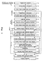
- Fig. 1 is a block diagram showing an overall structure of an ultrasonic diagnostic apparatus according to a preferred embodiment of the present invention.
- Figs. 2-5 are diagrams illustrating processes applied in each section of the ultrasonic diagnostic apparatus shown on Fig. 1. An operation of the ultrasonic diagnostic apparatus shown on Fig. 1 will be described referring to Figs. 2-5.
- An ultrasonic probe 10 is an ultrasonic probe for obtaining three-dimensional echo data.
- the ultrasonic probe 10 is used in contact with the skin of a patient or is inserted into a body cavity.
- the ultrasonic probe 10 transmits or receives ultrasound to or from a three-dimensional space by mechanically scanning a 1-D array oscillator which transmits or receives ultrasound to or from a two-dimensional space by electrical scanning.
- the ultrasonic probe 10 may transmit or receive ultrasound to or from a three-dimensional space by electrical scanning of a 2-D array oscillator formed by a two-dimensional matrix of oscillators.
- a transceiver section 12 controls the ultrasonic probe 10 and transmits or receives ultrasound to or from a three-dimensional space including a heart which is a target tissue.
- the transceiver section 12 functions as a transmission beam former and a reception beam former, obtains a voxel value for each voxel of a plurality of voxels forming a three-dimensional space, and outputs the voxel value to a noise removal processor 13.
- the noise removal processor 13 judges a voxel as a noise voxel for a voxel having a significantly different voxel value with respect to the surrounding voxel values and executes a removal process. For example, the noise removal processor 13 calculates an average value of the voxel values corresponding to a total of 27 voxels, the target voxel and 26 voxels spatially adjacent to the target voxel, and sets the calculated average value as the voxel value of the target voxel. As a result, noise voxels which are spatially isolated can be removed.
- the voxel values of voxels to which the noise removal process is applied are stored in a first three-dimensional data memory 14.
- each voxel value is stored at an address corresponding to the coordinates within the three-dimensional space.
- the voxel values are stored at addresses corresponding to the coordinate values in an xyz orthogonal coordinate system.
- the coordinate system used in the first three-dimensional data memory 14 may alternatively be, for example, an r ⁇ ⁇ polar coordinate system which is well suited for a sector scanning method of an ultrasonic beam.
- a binarization processor 16 obtains the voxel value of each voxel from the first three-dimensional data memory 14 and, based on a threshold (threshold value) set for the voxel value, separates the voxels into a group of voxels having a voxel value greater than or equal to the threshold and a group of voxels having a voxel value less than the threshold.
- the "voxel value” refers to an echo level or Doppler information corresponding to the voxel. In the present embodiment, the echo level is considered as the voxel value.
- an intracardial section of a heart has a smaller echo level than a cardiac muscle.
- the threshold is set at a level which is lower than a level corresponding to the cardinal muscle and higher than a level corresponding to the intracardial section. For example, when the echo level value is of 64 gradations, a level for separating the cardinal muscle and the intracardial section appears around levels 7 - 9.
- the voxel value is an echo value of 64 gradations and the threshold is set at 8.
- An inverted binarization process is applied in which a voxel value of a voxel originally having a voxel value of 8 or greater (cardinal muscle voxel corresponding to the cardinal muscle) is set to 0 and a voxel value of a voxel originally having a voxel value of less than 8 (intracardial section voxel corresponding to the intracardial section) is set to 1.
- the voxel values of the voxels to which the inverted binarization process is applied in the binarization processor 16 are stored in a second three-dimensional data memory 18.
- a labeling section 20 reads voxel values of voxels to which the inverted binarization process is applied from the second data memory 18 and applies a labeling process. Specifically, the labeling section 20 extracts a plurality of isolated groups of intracardial section voxels (voxels each having a voxel value of 1) from the group of voxel values to which the inverted binari zation process is applied and attaches a number to each of the isolated groups.
- a heart has four cavities respectively corresponding to a left ventricle, a left atrium, a right ventricle, and a right atrium. Thus, each of the extracted isolated groups corresponds to each of the four cavities.
- Fig. 2 is a diagram illustrating a group (volume data) of voxel values to which the labeling process is applied in the labeling section 20.
- the voxels are separated into cardinal muscle voxels andintracardialsection voxelsby theinverted binarization process.
- the cavities 50a - 50d correspond to the isolated groups of intracardial voxels.
- the portion 52 other than the cavities 50a - 50d correspond to a group of cardinal muscle voxels.
- the cavities 50a - 50d correspond respectively to the left ventricle, left atrium, right ventricle, and right atrium.
- the isolated groups are labeled with numbers 1 - 4 by the labeling section 20.
- a specific cavity extractor section 22 extracts an isolated group corresponding to the left ventricle from among the plurality of isolated groups to which numbers are attached in the labeling section 20. Because the cavity corresponding to the left ventricle has a larger volume than the other cavities, the specific cavity extractor section 22 extracts, from among the plurality of isolated groups, an isolated group having the maximum volume as the isolated group corresponding to the left ventricle (as a result of this, the cavity 50a assigned with a number of 1 in Fig. 2 is extracted). The volume of each isolated group is calculated from, for example, the number of voxels contained in the isolated group.
- the specific cavity extractor section 22 extracts an isolated group corresponding to the left ventricle based on a designated coordinate designated by a user in the case of "auto OFF", that is, when an automatic extraction process is stopped by an automatic On/Off signal.
- the setting of the designated coordinate by the user is performed by the user designating a point within a left ventricle in a cross sectional image using a pointing apparatus such as a trackball while the user views a three-dimensional image or a cross sectional image of the heart displayed on a display section 44.
- a designated coordinate is set at a point within the left ventricle, the specific cavity extractor section 22 extracts the isolated group containing the designated coordinate as the isolated group corresponding to the left ventricle.
- the designation by the user is not limited to the left ventricle, and, when extraction of other cavities such as the left atrium is desired, a designated coordinate may be set within the desired cavity and the specific cavity extractor section 22 may extract an isolated group corresponding to the desired cavity such as left atrium based on the designation by the user.
- an isolated group extracted in the labeling section 20 does not correspond to any of the four cavities.
- cavities corresponding to the left ventricle and left atrium are extracted as one isolated group in which the corresponding cavities are connected.
- the user sets a region of interest in a cavity corresponding to the left ventricle and the specific cavity extractor section 22 extracts the isolated group within the set region of interest as the isolated group corresponding to the left ventricle.
- the voxel values of the voxels to which the extraction process for the left ventricle cavity is applied in the specific cavity extractor section 22 are stored in a third three-dimensional data memory 24.
- a center-of-mass detector section 26 obtains the addresses of voxels to which the extraction process for the left ventricle cavity is applied from the third three-dimensional data memory 24 and determines a center of mass of the left ventricle cavity. Specifically, coordinates (Xo, Yo, Zo) of a volume center of mass of the left ventricle cavity in the xyz orthogonal coordinate system are calculated based on the three-dimensional coordinate values of all voxels corresponding to the left ventricle cavity. The calculated coordinates (Xo, Yo, Zo) of the center of mass is output to a major-axis end detector section 28.
- the major-axis end detector section 28 finds an end of a major axis (major-axis end point) which is positioned furthest away from the center of mass among voxels corresponding to the left ventricle cavity based on the coordinates (Xo, Yo, Zo) of the center of mass of the left ventricle cavity calculated in the center-of-mass detector section 26 and addresses of voxels obtained from the third three-dimensional data memory 24.
- the major-axis end detector section 28 calculates, for each voxel corresponding to the left ventricle cavity, a distance between the three dimensional coordinates of the voxel and the coordinates of the centerofmass (Xo, Yo, Zo), finds a voxel having the largest distance, and outputs the found voxel to a major-axis slope calculator section 30.
- the major-axis slope calculator section 30 sets a straight line passing through the center of mass calculated in the center-of-mass detector section 26 and the major-axis end point found in the major-axis end detector section 28 as a major axis of the left ventricle.
- the maj or-axis slope calculator section 30 calculates a slope ⁇ with respect to the x axis when the left ventricle major axis is projected onto the xy plane and a slope ⁇ with respect to the x axis when the left ventricle major axis is projected onto the zx plane.
- the major-axis slope calculator section 30 outputs these slopes to a three-dimensional data rotator section 32.
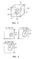
- Fig. 3 is a diagram illustrating a slope calculated in the major-axis slope calculator section 30.
- Figs. 3 (A) - (C) respectively represent a plan view, a front view, and a side view of a left ventricle cavity 60.
- the front view shown in Fig. 3 (B) is a view of the left ventricle cavity 60 projected onto the xy plane in the xyz orthogonal coordinate system.
- the slope of the left ventricle major axis 62 with respect to the x axis shown in the front view of Fig. 3 (B) is ⁇ .
- FIG. 3 (C) is a view of the left ventricle cavity 60 projected onto the zx plane in the xyz orthogonal coordinate system.
- the slope of the left ventricle major axis 62 with respect to the x axis shown in the side view of Fig. 3 (C) is ⁇ .
- the three-dimensional data rotator section 32 converts addresses of voxels in the second three-dimensional data memory 18 based on the center of mass calculated in the center-of-mass detector section 26 and slopes calculated in the major-axis slope calculator section 30 so that the left ventricle major axis becomes vertical with respect to the yz plane.
- the three-dimensional data rotator section 32 converts the three-dimensional coordinate values of the voxels so that the left ventricle major axis is rotated on the xy plane by an angle of - ⁇ and the left ventricle major axis is further rotated on the zx plane by an angle of - ⁇ .
- the voxel values of the voxels are stored in a fourth three-dimensional data memory 34 with addresses attached which corresponds to the coordinate values (coordinate values of x' y' z' orthogonal coordinate system) of voxels obtained as a result of the conversion.
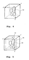
- Fig. 4 is a diagram illustrating volume data to which the coordinate conversion process is applied in the three-dimensional data rotator section 32.
- Fig. 4 shows a result of the coordinate conversion process applied to the volume data shown in Fig. 2.
- Fig. 4 shows a result of conversion, in the three-dimensional data rotator section 32, of three-dimensional coordinate values of the voxels to the x' y' z' orthogonal coordinate system so that the left ventricle major axis 62 becomes vertical with respect to the yz plane.
- a calculation of a cross sectional area in subsequent steps can be simplified. It is also advantageous in the diagnosis process to display a cross sectional image with the left ventricle major axis 62 pointing in a particular direction.
- a cavity cross sectional area calculator section 36 sets a cutting plane with respect to a heart and calculates a cavity cross sectional area which is an area of the cavity in the cutting plane based on the voxel values and addresses of voxels stored in the fourth three-dimensional data memory 34.
- the cutting plane is first set to a plane which is parallel to an x'y' plane in the x'y'z' orthogonal coordinate system and which includes the left ventricle major axis.
- a number of voxels on the cutting plane which has a voxel value of 1 is counted.
- the cavity cross sectional area calculator section 36 calculates the cross sectional area of the cavity based on the counted value.
- the group of voxels having a voxel value of 1 includes voxels corresponding to four cavities of the heart.
- the cross sectional area of cavity calculated in the cavity cross sectional area calculator section 36 corresponds to cross sectional areas regarding four cavities.
- the calculated cross sectional area of cavity is output to a comparator 38.
- Fig. 5 is a view illustrating setting of a cutting plane in the cavity cross sectional area calculator section 36.
- the cavity cross sectional area calculator section 36 calculates a cavity cross sectional area for each of a plurality of cutting planes including the left ventricle major axis 62.
- the cavity cross sectional area calculator section 36 calculates the cavity cross sectional area in the initial cutting plane, rotates the cutting plane 70 about the left ventricle major axis by a predetermined angle in a specified direction (rotational direction 72), calculates a cavity cross sectional area for each position of rotational angle until a rotational angle of 180° is reached, and outputs the calculated results to the comparator 38.
- the comparator 38 and a maximum value latch section 40 extract a maximum area from among the cavity cross sectional areas for positions at different rotational angles calculated in the cavity cross sectional area calculator section 36 and find a rotational angle ⁇ 1 of a cutting plane in which the maximum cavity cross sectional area can be obtained. More specifically, the comparator 38 compares the cavity cross sectional area in each position at a rotational angle sequentially output from the cavity cross sectional area calculator section 36 with a maximum cavity cross sectional area stored in the maximum value latch section 40.
- the cavity cross sectional area output from the cavity cross sectional area calculator section 36 is larger than the maximum cavity cross sectional area stored in the maximum value latch section 40, the cavity cross sectional area stored in the maximum value latch section 40 is replaced by the cavity cross sectional area output from the cavity cross sectional area calculator section 36.
- the comparator 38 compares each cavity cross sectional area for each rotational angle position from the initial cutting plane to a rotational angle of 180° with a cavity cross sectional area stored in the maximum value latch section 40.
- the maximum value latch section 40 outputs, to an optimum cross section setter 42, as ⁇ 1 , the rotational angle of the cutting plane ultimately stored in the maximum value latch section 40 as a result of comparisons of cavity cross sectional areas up to a rotational angle of 180°, the stored rotational angle corresponding to an angle in which the maximum cavity cross sectional area can be obtained.
- the detection of the rotational angle ⁇ 1 is performed in the cavity cross sectional area calculator section 36, for example, with the predetermined angle being 1° and in units of 1° from the initial cutting plane until the rotational angle of 180°.
- the optimum cross section setter 42 sets an optimum cross section based on the center of mass detected in the center-of-mass detector section 26, slopes calculated in the major-axis slope calculator section 30, and the rotational angle output from the maximum value latch section 40.
- the rotational angle ⁇ 1 output from the maximum value latch section 40 defines a cutting plane in which the cross sectional area with respect to four cavities becomes themaximum.
- a cutting plane which is rotated, about the left ventricle major axis, by a rotational angle of ⁇ 1 from a plane in the x' y' z' orthogonal coordinate system which is parallel to the x'y' plane and which contains the left ventricle major axis is defined as a cutting plane in which the cross sectional areas regarding four cavities are maximum.
- the optimum cross section setter 42 sets this cutting plane as a four-cavity cross section.
- the optimum cross section setter 42 also sets a plane which is orthogonal to the set four-cavity cross section and which contains the left ventricle major axis as a two-cavity cross section. Moreover, the optimum cross section setter 42 sets a plane which is orthogonal to the left ventricle major axis and which contains the center of mass of the left ventricle as aminor-axis cross section. In this manner, the four-cavity cross section, two-cavity cross section, and minor-axis cross section are set in the x'y'z' orthogonal coordinate system.
- the optimum cross section setter 42 sets cutting planes with respect to a plurality of voxel values stored in the first three-dimensional data memory 14, that is, for the group of three-dimensional image data.
- the voxel values stored in the first three-dimensional data memory 14 are stored, however, in addresses corresponding to the coordinate values in the xyz orthogonal coordinate system.
- the optimum cross section setter 42 applies a coordinate conversion process identical to the coordinate conversion process applied in the three-dimensional data rotator section 32 to the voxel values stored in the first three-dimensional data memory 14.
- the optimum cross section setter 42 converts the three-dimensional coordinate values of the voxels such that the left ventricle major axis is rotated by an angle of- ⁇ on the xy plane and the left ventricle maj or axis is rotated by an angle of - ⁇ on the zx plane.
- the coordinate values of voxels are converted into coordinate values of the x'y'z' orthogonal coordinate system.
- the optimum cross section setter 42 sets the four-cavity cross section, two-cavity cross section, and minor-axis cross section for a group of three-dimensional image data in which the coordinate values are converted to the x' y' z' orthogonal coordinate system.
- the optimum cross section setter 42 creates a cross sectional image of the heart in each cross section and creates a stereographical image of the heart based on the group of three-dimensional image data.
- the optimum cross section setter 42 further forms a three-dimensional image in which plane images indicating the positions of the four-cavity cross section, two-cavity cross section, and minor-axis cross section are incorporated into the formed stereographical image of the heart.
- the three-dimensional image and cross sectional image in each cross section both of which are formed in the optimum cross section setter 42 are displayed on the display section 44.
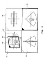
- Fig. 6 is a diagram showing images displayed on the display section 44, and shows a three-dimensional image 80 including the four cavities of the heart, a four-cavity cross sectional image 82 at the four-cavity cross section, a two-cavity cross sectional image 84 at the two-cavity cross section, and a minor-axis cross sectional image 86 at the minor axis cross section.
- a cursor 82' for four-cavity cross section, a cursor 84' for two-cavity cross section, and a cursor 86' for minor-axis cross section are incorporated.
- each cursor is displayed in the position of the corresponding cross section, the user can identify the formation position of each cross sectional image based on the position of the cursor on the three-dimensional image 80. The user can change the positions of the cross sections as necessary while viewing the displayed image shown in Fig. 6.
- a four-cavity cross section, a two-cavity cross section, and a minor-axis cross section are set for a heart.
- the cross section which can be set by the ultrasonic diagnostic equipment of the present invention is not, however, limited to these cross sections.
- the cavity cross sectional area calculator section 36 it is possible to consider the cross sectional area of the left ventricle cavity alone and define a cutting plane in which the cross sectional area of the left ventricle cavity is maximized. Then, three orthogonal cross sections regarding the left ventricle can be set by setting two cross sections which are orthogonal to the cutting plane in the optimum cross section setter 42.
- the target tissue is not limited to the heart, and cross sections regarding other tissues may also be set.
- a configuration is shown in which a maximum cross sectional area is found from among cavity cross sections at various rotational angles using a cavity cross-sectional area calculator section 36, comparator 38, and a maximum value latch section 40.
- a cross section having the minimum cross sectional area from among the cavity cross sections at various rotational angles.
- peripheral lengths of the cavity cross sections at various rotational angles are determined and a cross section is extracted in which the peripheral length is maximized or minimized.
Landscapes
- Engineering & Computer Science (AREA)
- Health & Medical Sciences (AREA)
- Life Sciences & Earth Sciences (AREA)
- Physics & Mathematics (AREA)
- General Physics & Mathematics (AREA)
- Surgery (AREA)
- General Health & Medical Sciences (AREA)
- Veterinary Medicine (AREA)
- Biophysics (AREA)
- Nuclear Medicine, Radiotherapy & Molecular Imaging (AREA)
- Pathology (AREA)
- Radiology & Medical Imaging (AREA)
- Biomedical Technology (AREA)
- Heart & Thoracic Surgery (AREA)
- Medical Informatics (AREA)
- Molecular Biology (AREA)
- Public Health (AREA)
- Animal Behavior & Ethology (AREA)
- Theoretical Computer Science (AREA)
- Computer Networks & Wireless Communication (AREA)
- Radar, Positioning & Navigation (AREA)
- Remote Sensing (AREA)
- Cardiology (AREA)
- Computer Vision & Pattern Recognition (AREA)
- Geometry (AREA)
- Computer Graphics (AREA)
- Computer Hardware Design (AREA)
- General Engineering & Computer Science (AREA)
- Software Systems (AREA)
- Ultra Sonic Daignosis Equipment (AREA)
- Image Processing (AREA)
- Image Analysis (AREA)
Abstract
Description
Claims (19)
- An ultrasonic diagnostic apparatus for obtaining volume data made of voxel values for voxels forming a three-dimensional space by transmitting and receiving ultrasound to and from the three-dimensional space containing a target tissue and for applying a data process with respect to the volume data, the ultrasonic diagnostic apparatus comprising:a basis axis setter for setting a basis axis in the target tissue based on a characteristic of the target tissue;a reference cross section setter for setting, with respect to the target tissue, a plurality of reference cross sections which intersect each other with the basis axis as a reference;a basis cross section selector for selecting a basis cross section from among the plurality of reference cross sections based on a cross sectional characteristic of the target tissue in each of the reference cross sections; anda cross sectional image former for forming a cross sectional image of the target tissue, the cross sectional image corresponding to one of cross sections set with the basis cross section as a reference and the basis cross section.
- The ultrasonic diagnostic apparatus according to Claim 1, wherein
the basis axis setter sets the basis axis based on two characteristic points of the target tissue. - The ultrasonic diagnostic apparatus according to Claim 1, wherein
the basis axis setter sets the basis axis based on a center of mass of the target tissue and one characteristic point of the target tissue other than the center of mass. - The ultrasonic diagnostic apparatus according to Claim 1, wherein
the basis axis setter sets the basis axis based on the center of mass of the target tissue and an end, in the target tissue, which is furthest away from the center of mass. - The ultrasonic diagnostic apparatus according to Claim 1, wherein
the reference cross section setter sequentially rotates a specific plane containing the basis axis by a predetermined angle with the basis axis as an axis of rotation to set the planes formed in each rotational angle position as the plurality of reference cross sections. - The ultrasonic diagnostic apparatus according to Claim 1, wherein
the basis cross section selector calculates an area of a cross section of the target tissue in each reference cross section and selects, as the basis cross section, a reference cross section having a maximum cross sectional area or a minimum cross sectional area. - The ultrasonic diagnostic apparatus according to Claim 1, wherein
thebasis cross section selector calculates aperipheral length of the target tissue in each reference cross section and selects, as the basis cross section, a reference cross section in which a longest peripheral length or a shortest peripheral length can be obtained. - An ultrasonic diagnostic apparatus for obtaining volume data made of voxel values for voxels forming a transmission space by transmitting and receiving ultrasound to or from a heart having four cavities including a left ventricle cavity and for applying a data process to the volume data, the ultrasonic diagnostic apparatus comprising:a major axis setter for setting a left ventricle major axis based on the shape of the left ventricle cavity;a reference cross section setter for setting a plurality of reference cross sections each having a different rotational angle from each other, with the left ventricle major axis as an axis of rotation;a basis cross section selector for selecting a basis cross section from among the plurality of reference cross sections based on a size of a cross section of the four cavities in each of the reference cross sections; anda cross sectional image former for forming a cross sectional image corresponding to at least one of a four-cavity cross section, a two-cavity cross section, and a minor-axis cross section, all of which relate to the heart, based on the basis cross section.
- The ultrasonic diagnostic apparatus according to Claim 8, further comprising:a binarization section for separating the voxels into cavity tissue voxels and real tissue voxels to create binarized volume data;a cavity group extractor for extracting a plurality of cavity groups each made of a plurality of cavity tissue voxels based on the binarized volume data; anda left ventricle cavity selector for selecting a left ventricle cavity group corresponding to the left ventricle cavity from among the plurality of cavity groups, whereinthe major axis setter judges the shape of the left ventricle cavity based on the left ventricle cavity group.
- An ultrasonic diagnostic equipment according to Claim 8, wherein
the basis cross section selector calculates a cross sectional area of the four cavities in each of the reference cross sections and selects, as the basis cross section, a reference cross section in which a maximum cross sectional area can be obtained, and
the cross sectional image former sets the basis cross section as the four-cavity cross section. - The ultrasonic diagnostic device according to Claim 10, wherein
the two-cavity cross section is a cross section which is orthogonal to the basis cross section and which contains the left ventricle major axis. - The ultrasonic diagnostic apparatus according to Claim 10, wherein
the minor-axis cross section is a cross section which is orthogonal to the left ventricle major axis and which contains a center of mass of the left ventricle cavity. - The ultrasonic diagnostic apparatus according to Claim 8, further comprising:a three-dimensional image former for forming a three-dimensional image in which at least one cursor indicating at least one of the positions of the four-cavity cross section, the two-cavity cross section, and the minor-axis cross section is displayed on a stereographical image of the heart obtained based on the volume data.
- An ultrasonic diagnostic apparatus for obtaining, from an ultrasonic probe for transmitting and receiving ultrasound to and from a transmission space containing a heart, volume data made of voxel values of voxels forming the transmission space, and for applying a data process to the volume data, the ultrasonic diagnostic apparatus comprising:a major axis setter for setting a left ventricle major axis based on a shape of a left ventricle cavity of the heart;a reference cross section setter for setting a plurality of reference cross sections each having a different rotational angle, with the left ventricle major axis as an axis of rotation;a basis cross section selector for selecting a basis cross section from among the plurality of reference cross sections based on a size of a cross section of the four cavities in each of the reference cross sections; anda cross sectional image data former for forming, based on the basis cross section, image data of a cross sectional image corresponding to at least one of a four-cavity cross section, a two-cavity cross section, and a minor-axis cross section regarding the heart.
- The ultrasonic diagnostic apparatus according to Claim 14, further comprising:a binarization section for separating the voxels into cavity tissue voxels and real tissue voxels to create binarized volume data;a cavity group extractor for extracting, based on the binarized volume data, a plurality of cavity groups each made of a plurality of cavity tissue voxels; anda left ventricle cavity selector for selecting a left ventricle cavity group corresponding to the left ventricle cavity from among the plurality of cavity groups, whereinthe major axis setter judges a shape of the left ventricle cavity based on the left ventricle cavity group.
- The ultrasonic diagnostic apparatus according to Claim 15, wherein
the basis cross section selector calculates a cross sectional area of the four cavities in each of the reference cross sections and selects, as the basis cross section, a reference cross section in which a maximum cross sectional area can be obtained, and
the cross sectional image former sets the basis cross section as the four-cavity cross section. - The ultrasonic diagnostic apparatus according to Claim 16, wherein
the two-cavity cross section is a cross section which is orthogonal to the basis cross section and which contains the left ventricle major axis. - The ultrasonic diagnostic apparatus according to Claim 17, wherein
the minor-axis cross section is a cross section which is orthogonal to the left ventricle major axis and contains a center of mass of the left ventricle cavity. - The ultrasonic diagnostic apparatus according to Claim 18, further comprising:a three-dimensional image data former for forming image data of a three-dimensional image in which at least one cursor indicating at least one of the positions of the four-cavity cross section, the two-cavity cross section, and the minor-axis cross section is displayed on a stereographical image of the heart obtained based on the volume data.
Applications Claiming Priority (2)
| Application Number | Priority Date | Filing Date | Title |
|---|---|---|---|
| JP2003115340 | 2003-04-21 | ||
| JP2003115340A JP3802508B2 (en) | 2003-04-21 | 2003-04-21 | Ultrasonic diagnostic equipment |
Publications (3)
| Publication Number | Publication Date |
|---|---|
| EP1470784A2 true EP1470784A2 (en) | 2004-10-27 |
| EP1470784A3 EP1470784A3 (en) | 2004-11-17 |
| EP1470784B1 EP1470784B1 (en) | 2009-11-11 |
Family
ID=32959572
Family Applications (1)
| Application Number | Title | Priority Date | Filing Date |
|---|---|---|---|
| EP04002558A Expired - Lifetime EP1470784B1 (en) | 2003-04-21 | 2004-02-05 | Ultrasonic diagnostic apparatus |
Country Status (4)
| Country | Link |
|---|---|
| US (1) | US7604597B2 (en) |
| EP (1) | EP1470784B1 (en) |
| JP (1) | JP3802508B2 (en) |
| DE (1) | DE602004023991D1 (en) |
Cited By (4)
| Publication number | Priority date | Publication date | Assignee | Title |
|---|---|---|---|---|
| US20110028842A1 (en) * | 2009-07-30 | 2011-02-03 | Medison Co., Ltd. | Providing A Plurality Of Slice Images In An Ultrasound System |
| US20110028841A1 (en) * | 2009-07-30 | 2011-02-03 | Medison Co., Ltd. | Setting a Sagittal View In an Ultrasound System |
| WO2014162232A1 (en) * | 2013-04-03 | 2014-10-09 | Koninklijke Philips N.V. | 3d ultrasound imaging system |
| EP2639764B1 (en) * | 2012-03-16 | 2019-04-17 | Carestream Dental Technology Topco Limited | Interactive 3-D examination of root fractures |
Families Citing this family (38)
| Publication number | Priority date | Publication date | Assignee | Title |
|---|---|---|---|---|
| JP4563788B2 (en) * | 2004-12-15 | 2010-10-13 | アロカ株式会社 | Ultrasonic diagnostic equipment |
| PL1874192T3 (en) * | 2005-04-14 | 2017-12-29 | Verasonics, Inc. | Ultrasound imaging system with pixel oriented processing |
| JP4786229B2 (en) * | 2005-06-24 | 2011-10-05 | 株式会社東芝 | Ultrasonic diagnostic equipment |
| EP1872724B1 (en) * | 2006-01-10 | 2019-08-28 | Toshiba Medical Systems Corporation | Ultrasonograph and ultrasonogram creating method |
| US8224047B2 (en) * | 2006-09-01 | 2012-07-17 | Koninklijke Philips Electronics N.V. | System and method for measuring left ventricular torsion |
| US11275242B1 (en) | 2006-12-28 | 2022-03-15 | Tipping Point Medical Images, Llc | Method and apparatus for performing stereoscopic rotation of a volume on a head display unit |
| US10795457B2 (en) | 2006-12-28 | 2020-10-06 | D3D Technologies, Inc. | Interactive 3D cursor |
| US11315307B1 (en) | 2006-12-28 | 2022-04-26 | Tipping Point Medical Images, Llc | Method and apparatus for performing rotating viewpoints using a head display unit |
| US11228753B1 (en) | 2006-12-28 | 2022-01-18 | Robert Edwin Douglas | Method and apparatus for performing stereoscopic zooming on a head display unit |
| US20090153548A1 (en) * | 2007-11-12 | 2009-06-18 | Stein Inge Rabben | Method and system for slice alignment in diagnostic imaging systems |
| US8494250B2 (en) * | 2008-06-06 | 2013-07-23 | Siemens Medical Solutions Usa, Inc. | Animation for conveying spatial relationships in three-dimensional medical imaging |
| JP5276407B2 (en) * | 2008-10-15 | 2013-08-28 | 日立アロカメディカル株式会社 | Ultrasonic diagnostic equipment |
| EP2193747B8 (en) * | 2008-12-02 | 2015-06-17 | Samsung Medison Co., Ltd. | Ultrasound system and method of providing orientation help view |
| JP5762576B2 (en) * | 2009-01-30 | 2015-08-12 | 株式会社東芝 | Ultrasonic diagnostic apparatus, ultrasonic image processing apparatus, medical image diagnostic apparatus, and medical image processing apparatus |
| JP4810583B2 (en) * | 2009-03-26 | 2011-11-09 | 株式会社東芝 | Ultrasonic diagnostic apparatus, ultrasonic diagnostic method, and ultrasonic diagnostic program |
| JP5787471B2 (en) * | 2009-07-01 | 2015-09-30 | 株式会社東芝 | Ultrasonic inspection equipment |
| KR101121379B1 (en) | 2009-09-03 | 2012-03-09 | 삼성메디슨 주식회사 | Ultrasound system and method for providing a plurality of plane images corresponding to a plurality of view |
| JP5586203B2 (en) * | 2009-10-08 | 2014-09-10 | 株式会社東芝 | Ultrasonic diagnostic apparatus, ultrasonic image processing apparatus, and ultrasonic image processing program |
| JP2011125568A (en) * | 2009-12-18 | 2011-06-30 | Canon Inc | Image processor, image processing method, program and image processing system |
| EP2520211B1 (en) * | 2010-02-10 | 2014-04-23 | Olympus Corporation | Fluorescence endoscope device |
| JP5460484B2 (en) * | 2010-06-23 | 2014-04-02 | 日立アロカメディカル株式会社 | Ultrasonic data processor |
| JP5650021B2 (en) * | 2011-03-03 | 2015-01-07 | 国立大学法人 東京大学 | Three-dimensional environment restoration apparatus, processing method thereof, and program |
| JP5087694B2 (en) * | 2011-04-14 | 2012-12-05 | 日立アロカメディカル株式会社 | Ultrasonic diagnostic equipment |
| JP5926909B2 (en) | 2011-09-07 | 2016-05-25 | オリンパス株式会社 | Fluorescence observation equipment |
| CN104219997B (en) * | 2012-05-22 | 2016-12-28 | 东芝医疗系统株式会社 | Medical image diagnosis device and image display device |
| KR101517752B1 (en) | 2012-06-28 | 2015-05-06 | 삼성메디슨 주식회사 | Diagnosis image apparatus and operating method thereof |
| KR101538658B1 (en) | 2012-11-20 | 2015-07-22 | 삼성메디슨 주식회사 | Medical image display method and apparatus |
| WO2014155223A1 (en) * | 2013-03-25 | 2014-10-02 | Koninklijke Philips N.V. | Segmentation of planar contours of target anatomy in 3d ultrasound images |
| WO2015068099A1 (en) * | 2013-11-05 | 2015-05-14 | Koninklijke Philips N.V. | Automated segmentation of tri-plane images for real time ultrasonic imaging |
| KR102156297B1 (en) | 2014-04-17 | 2020-09-15 | 삼성메디슨 주식회사 | Medical image apparatus and operating method for the same |
| JP6359337B2 (en) * | 2014-05-21 | 2018-07-18 | 株式会社日立製作所 | Ultrasonic diagnostic equipment |
| US9808213B2 (en) * | 2014-08-11 | 2017-11-07 | Canon Kabushiki Kaisha | Image processing apparatus, image processing method, medical image diagnostic system, and storage medium |
| JP5908549B2 (en) * | 2014-09-08 | 2016-04-26 | 株式会社東芝 | Ultrasonic inspection equipment |
| JP6744141B2 (en) * | 2015-06-16 | 2020-08-19 | キヤノンメディカルシステムズ株式会社 | Ultrasonic diagnostic device and image processing device |
| CN106725598B (en) * | 2016-12-28 | 2023-09-12 | 苏州科技城医院 | Cardiac ultrasound system and imaging method based on multiple transcutaneous ultrasound transducers |
| US20210196237A1 (en) * | 2019-12-31 | 2021-07-01 | Butterfly Network, Inc. | Methods and apparatuses for modifying the location of an ultrasound imaging plane |
| WO2021166247A1 (en) * | 2020-02-21 | 2021-08-26 | オリンパス株式会社 | Information transmission method and system |
| JP2023125697A (en) * | 2022-02-28 | 2023-09-07 | 国立大学法人電気通信大学 | Image evaluation device and program |
Family Cites Families (16)
| Publication number | Priority date | Publication date | Assignee | Title |
|---|---|---|---|---|
| US5497776A (en) * | 1993-08-05 | 1996-03-12 | Olympus Optical Co., Ltd. | Ultrasonic image diagnosing apparatus for displaying three-dimensional image |
| US5920319A (en) * | 1994-10-27 | 1999-07-06 | Wake Forest University | Automatic analysis in virtual endoscopy |
| US5825908A (en) * | 1995-12-29 | 1998-10-20 | Medical Media Systems | Anatomical visualization and measurement system |
| US5771895A (en) * | 1996-02-12 | 1998-06-30 | Slager; Cornelis J. | Catheter for obtaining three-dimensional reconstruction of a vascular lumen and wall |
| US7194117B2 (en) * | 1999-06-29 | 2007-03-20 | The Research Foundation Of State University Of New York | System and method for performing a three-dimensional virtual examination of objects, such as internal organs |
| US6859548B2 (en) | 1996-09-25 | 2005-02-22 | Kabushiki Kaisha Toshiba | Ultrasonic picture processing method and ultrasonic picture processing apparatus |
| US5891030A (en) * | 1997-01-24 | 1999-04-06 | Mayo Foundation For Medical Education And Research | System for two dimensional and three dimensional imaging of tubular structures in the human body |
| US6148095A (en) * | 1997-09-08 | 2000-11-14 | University Of Iowa Research Foundation | Apparatus and method for determining three-dimensional representations of tortuous vessels |
| US6928314B1 (en) * | 1998-01-23 | 2005-08-09 | Mayo Foundation For Medical Education And Research | System for two-dimensional and three-dimensional imaging of tubular structures in the human body |
| EP0974931A1 (en) | 1998-07-24 | 2000-01-26 | Xerox Corporation | Method and apparatus for identifying a plurality of sub-images in an input image |
| US6352509B1 (en) | 1998-11-16 | 2002-03-05 | Kabushiki Kaisha Toshiba | Three-dimensional ultrasonic diagnosis apparatus |
| US6342889B1 (en) | 1998-11-27 | 2002-01-29 | Dicomit Dicom Information Technologies Corp. | Method and system for selecting at least one optimal view of a three dimensional image |
| WO2001093745A2 (en) * | 2000-06-06 | 2001-12-13 | The Research Foundation Of State University Of New York | Computer aided visualization, fusion and treatment planning |
| JP2004516584A (en) * | 2000-12-21 | 2004-06-03 | コーニンクレッカ フィリップス エレクトロニクス エヌ ヴィ | How to analyze a dataset of tubular structures |
| JP4653324B2 (en) | 2001-02-20 | 2011-03-16 | 東芝医用システムエンジニアリング株式会社 | Image display apparatus, image display program, image processing apparatus, and medical image diagnostic apparatus |
| JP3905470B2 (en) | 2002-12-26 | 2007-04-18 | アロカ株式会社 | Ultrasonic diagnostic equipment |
-
2003
- 2003-04-21 JP JP2003115340A patent/JP3802508B2/en not_active Expired - Fee Related
-
2004
- 2004-02-04 US US10/771,816 patent/US7604597B2/en not_active Expired - Fee Related
- 2004-02-05 DE DE602004023991T patent/DE602004023991D1/en not_active Expired - Lifetime
- 2004-02-05 EP EP04002558A patent/EP1470784B1/en not_active Expired - Lifetime
Cited By (8)
| Publication number | Priority date | Publication date | Assignee | Title |
|---|---|---|---|---|
| US20110028842A1 (en) * | 2009-07-30 | 2011-02-03 | Medison Co., Ltd. | Providing A Plurality Of Slice Images In An Ultrasound System |
| US20110028841A1 (en) * | 2009-07-30 | 2011-02-03 | Medison Co., Ltd. | Setting a Sagittal View In an Ultrasound System |
| EP2281509A1 (en) * | 2009-07-30 | 2011-02-09 | Medison Co., Ltd. | Setting a Sagittal View in an Ultrasound System |
| EP2281510A1 (en) * | 2009-07-30 | 2011-02-09 | Medison Co., Ltd. | Providing a plurality of slice images in an ultrasound system |
| US9216007B2 (en) | 2009-07-30 | 2015-12-22 | Samsung Medison Co., Ltd. | Setting a sagittal view in an ultrasound system |
| EP2639764B1 (en) * | 2012-03-16 | 2019-04-17 | Carestream Dental Technology Topco Limited | Interactive 3-D examination of root fractures |
| WO2014162232A1 (en) * | 2013-04-03 | 2014-10-09 | Koninklijke Philips N.V. | 3d ultrasound imaging system |
| RU2657855C2 (en) * | 2013-04-03 | 2018-06-15 | Конинклейке Филипс Н.В. | Three-dimensional ultrasound imaging system |
Also Published As
| Publication number | Publication date |
|---|---|
| US7604597B2 (en) | 2009-10-20 |
| JP2004313651A (en) | 2004-11-11 |
| EP1470784B1 (en) | 2009-11-11 |
| DE602004023991D1 (en) | 2009-12-24 |
| JP3802508B2 (en) | 2006-07-26 |
| US20040210138A1 (en) | 2004-10-21 |
| EP1470784A3 (en) | 2004-11-17 |
Similar Documents
| Publication | Publication Date | Title |
|---|---|---|
| US7604597B2 (en) | Ultrasonic diagnostic apparatus | |
| CN112568988B (en) | Multi-frequency mapping catheter and mapping method | |
| EP2016905B1 (en) | Ultrasound diagnostic apparatus | |
| JP5265849B2 (en) | Method and system for 3D segmentation of ultrasound images | |
| EP1600891A1 (en) | Ultrasonic diagnostic apparatus and image processing method | |
| EP2698114B1 (en) | Ultrasound diagnostic device | |
| EP2016906B1 (en) | Ultrasound diagnostic apparatus | |
| EP2732769B1 (en) | Method and apparatus for displaying medical image | |
| US20130150718A1 (en) | Ultrasound imaging system and method for imaging an endometrium | |
| US9449425B2 (en) | Apparatus and method for generating medical image | |
| JP2009011468A (en) | Ultrasound diagnosis apparatus | |
| CN113040822A (en) | Method for measuring endometrial peristalsis and device for measuring endometrial peristalsis | |
| EP1419737B1 (en) | Ultrasonic diagnostic apparatus | |
| JP4205957B2 (en) | Ultrasonic diagnostic equipment | |
| US7376254B2 (en) | Method for surface-contouring of a three-dimensional image | |
| EP1952359A1 (en) | System and method for generating for display two-dimensional echocardiography views from a three-dimensional image | |
| JP4109575B2 (en) | Ultrasonic image processing apparatus and three-dimensional data processing method | |
| JP4129199B2 (en) | Ultrasonic diagnostic equipment | |
| JP4050169B2 (en) | Ultrasonic diagnostic equipment | |
| JP4071101B2 (en) | Ultrasonic diagnostic equipment | |
| US11559280B2 (en) | Ultrasound imaging system and method for determining acoustic contact | |
| JP4373544B2 (en) | Ultrasonic diagnostic equipment | |
| US11900524B2 (en) | Constructing topography of lumen wall in 4D ultrasound image with virtual ellipsoid or polyhedron | |
| EP4461230A1 (en) | Ultrasound system | |
| JP3898978B2 (en) | Ultrasonic diagnostic apparatus and ultrasonic image forming method |
Legal Events
| Date | Code | Title | Description |
|---|---|---|---|
| PUAI | Public reference made under article 153(3) epc to a published international application that has entered the european phase |
Free format text: ORIGINAL CODE: 0009012 |
|
| PUAL | Search report despatched |
Free format text: ORIGINAL CODE: 0009013 |
|
| AK | Designated contracting states |
Kind code of ref document: A2 Designated state(s): AT BE BG CH CY CZ DE DK EE ES FI FR GB GR HU IE IT LI LU MC NL PT RO SE SI SK TR |
|
| AX | Request for extension of the european patent |
Extension state: AL LT LV MK |
|
| AK | Designated contracting states |
Kind code of ref document: A3 Designated state(s): AT BE BG CH CY CZ DE DK EE ES FI FR GB GR HU IE IT LI LU MC NL PT RO SE SI SK TR |
|
| AX | Request for extension of the european patent |
Extension state: AL LT LV MK |
|
| RIC1 | Information provided on ipc code assigned before grant |
Ipc: 7G 06T 17/40 B Ipc: 7G 01S 15/89 B Ipc: 7A 61B 8/00 A |
|
| 17P | Request for examination filed |
Effective date: 20041122 |
|
| AKX | Designation fees paid |
Designated state(s): DE FR GB IT |
|
| 17Q | First examination report despatched |
Effective date: 20070305 |
|
| GRAP | Despatch of communication of intention to grant a patent |
Free format text: ORIGINAL CODE: EPIDOSNIGR1 |
|
| GRAS | Grant fee paid |
Free format text: ORIGINAL CODE: EPIDOSNIGR3 |
|
| GRAA | (expected) grant |
Free format text: ORIGINAL CODE: 0009210 |
|
| AK | Designated contracting states |
Kind code of ref document: B1 Designated state(s): DE FR GB IT |
|
| REG | Reference to a national code |
Ref country code: GB Ref legal event code: FG4D |
|
| REF | Corresponds to: |
Ref document number: 602004023991 Country of ref document: DE Date of ref document: 20091224 Kind code of ref document: P |
|
| PLBE | No opposition filed within time limit |
Free format text: ORIGINAL CODE: 0009261 |
|
| STAA | Information on the status of an ep patent application or granted ep patent |
Free format text: STATUS: NO OPPOSITION FILED WITHIN TIME LIMIT |
|
| 26N | No opposition filed |
Effective date: 20100812 |
|
| REG | Reference to a national code |
Ref country code: DE Ref legal event code: R082 Ref document number: 602004023991 Country of ref document: DE Representative=s name: WEBER & HEIM PATENTANWAELTE, DE |
|
| REG | Reference to a national code |
Ref country code: FR Ref legal event code: CD |
|
| REG | Reference to a national code |
Ref country code: DE Ref legal event code: R081 Ref document number: 602004023991 Country of ref document: DE Owner name: HITACHI ALOKA MEDICAL, LTD., JP Free format text: FORMER OWNER: ALOKA CO. LTD., MITAKA, TOKIO/TOKYO, JP Effective date: 20110826 Ref country code: DE Ref legal event code: R082 Ref document number: 602004023991 Country of ref document: DE Representative=s name: WEBER & HEIM PATENTANWAELTE, DE Effective date: 20110826 Ref country code: DE Ref legal event code: R081 Ref document number: 602004023991 Country of ref document: DE Owner name: HITACHI ALOKA MEDICAL, LTD., JP Free format text: FORMER OWNER: ALOKA CO. LTD., MITAKA, JP Effective date: 20110826 Ref country code: DE Ref legal event code: R082 Ref document number: 602004023991 Country of ref document: DE Representative=s name: WEBER & HEIM PATENTANWAELTE PARTNERSCHAFTSGESE, DE Effective date: 20110826 |
|
| PGFP | Annual fee paid to national office [announced via postgrant information from national office to epo] |
Ref country code: DE Payment date: 20140225 Year of fee payment: 11 |
|
| PGFP | Annual fee paid to national office [announced via postgrant information from national office to epo] |
Ref country code: FR Payment date: 20140211 Year of fee payment: 11 Ref country code: IT Payment date: 20140227 Year of fee payment: 11 |
|
| PGFP | Annual fee paid to national office [announced via postgrant information from national office to epo] |
Ref country code: GB Payment date: 20140120 Year of fee payment: 11 |
|
| REG | Reference to a national code |
Ref country code: DE Ref legal event code: R119 Ref document number: 602004023991 Country of ref document: DE |
|
| GBPC | Gb: european patent ceased through non-payment of renewal fee |
Effective date: 20150205 |
|
| REG | Reference to a national code |
Ref country code: FR Ref legal event code: ST Effective date: 20151030 |
|
| PG25 | Lapsed in a contracting state [announced via postgrant information from national office to epo] |
Ref country code: IT Free format text: LAPSE BECAUSE OF NON-PAYMENT OF DUE FEES Effective date: 20150205 |
|
| PG25 | Lapsed in a contracting state [announced via postgrant information from national office to epo] |
Ref country code: DE Free format text: LAPSE BECAUSE OF NON-PAYMENT OF DUE FEES Effective date: 20150901 Ref country code: GB Free format text: LAPSE BECAUSE OF NON-PAYMENT OF DUE FEES Effective date: 20150205 |
|
| PG25 | Lapsed in a contracting state [announced via postgrant information from national office to epo] |
Ref country code: FR Free format text: LAPSE BECAUSE OF NON-PAYMENT OF DUE FEES Effective date: 20150302 |