EP2637270A2 - Cadre amovible pour un appareil de commutation électrique enfichable, notamment un disjoncteur enfichable - Google Patents
Cadre amovible pour un appareil de commutation électrique enfichable, notamment un disjoncteur enfichable Download PDFInfo
- Publication number
- EP2637270A2 EP2637270A2 EP12194548.9A EP12194548A EP2637270A2 EP 2637270 A2 EP2637270 A2 EP 2637270A2 EP 12194548 A EP12194548 A EP 12194548A EP 2637270 A2 EP2637270 A2 EP 2637270A2
- Authority
- EP
- European Patent Office
- Prior art keywords
- crank
- slide
- guide slot
- frame
- locking position
- Prior art date
- Legal status (The legal status is an assumption and is not a legal conclusion. Google has not performed a legal analysis and makes no representation as to the accuracy of the status listed.)
- Granted
Links
- 238000003780 insertion Methods 0.000 claims abstract description 67
- 230000037431 insertion Effects 0.000 claims abstract description 66
- 238000012546 transfer Methods 0.000 claims abstract description 8
- 238000012360 testing method Methods 0.000 claims description 11
- 230000000903 blocking effect Effects 0.000 claims description 5
- 238000011161 development Methods 0.000 description 7
- 238000013461 design Methods 0.000 description 5
- 238000006073 displacement reaction Methods 0.000 description 4
- 230000002996 emotional effect Effects 0.000 description 1
- 230000003993 interaction Effects 0.000 description 1
- 230000005405 multipole Effects 0.000 description 1
- 238000000926 separation method Methods 0.000 description 1
Images


Classifications
-
- H—ELECTRICITY
- H02—GENERATION; CONVERSION OR DISTRIBUTION OF ELECTRIC POWER
- H02B—BOARDS, SUBSTATIONS OR SWITCHING ARRANGEMENTS FOR THE SUPPLY OR DISTRIBUTION OF ELECTRIC POWER
- H02B1/00—Frameworks, boards, panels, desks, casings; Details of substations or switching arrangements
- H02B1/26—Casings; Parts thereof or accessories therefor
- H02B1/30—Cabinet-type casings; Parts thereof or accessories therefor
- H02B1/32—Mounting of devices therein
- H02B1/34—Racks
- H02B1/36—Racks with withdrawable units
-
- H—ELECTRICITY
- H02—GENERATION; CONVERSION OR DISTRIBUTION OF ELECTRIC POWER
- H02B—BOARDS, SUBSTATIONS OR SWITCHING ARRANGEMENTS FOR THE SUPPLY OR DISTRIBUTION OF ELECTRIC POWER
- H02B11/00—Switchgear having carriage withdrawable for isolation
- H02B11/12—Switchgear having carriage withdrawable for isolation with isolation by horizontal withdrawal
- H02B11/127—Withdrawal mechanism
- H02B11/133—Withdrawal mechanism with interlock
Definitions
- circuit breakers have the task of decoupling one or a number of consumers from a power supply network when a specific fault occurs.
- the classic failure is the occurrence of a short circuit current, and the circuit breakers are conventionally designed to move a switching element in such a short-circuit current and thus to decouple the connection between consumers and power supply network.
- the invention relates to slide-in frame for electrical plug-in switching devices, in particular on withdrawable circuit breaker in the low voltage range.
- low voltage is meant typically voltages of up to about 2000 volts.
- switching devices can be designed for switching voltages above 2000 volts, such. up to 6.3 kV.
- electrical drawer switching devices such as low-voltage circuit breaker, are designed for interrupting current paths in an overcurrent case or in a short circuit case. They can be single-pole or multi-pole, in particular three-pole.
- circuit breaker for a simple and quick assembly or disassembly, for example, in a push-in frame with an adapter socket, which is usually designed as a plug-in or plug-in socket.
- the adapter sockets have connections on the input side and output side to which the lines of the power supply and the electric circuits to be supplied with electrical energy are connected be connected to their consumers.
- the circuit breaker on its front usually a manually operable lever. It can be provided with the appropriate socket size for each housing size, such as a series, an adapter base.
- a crank is preferably used for lowering and raising an inserted into a drawer electrical drawer switching device.
- the electrical drawer switch can be moved within the drawer frame to be connected to or disconnected from the adapter socket. That is, the electrical drawer switching device can be coupled to the crank of the drawer frame such that upon rotation of the crank in a first direction, the electrical drawer switching device is pulled into the drawer frame, in particular in the direction of the adapter socket, while the electrical drawer switching device in the rotation of Crank is moved away in a direction opposite to the first direction of the second direction of the adapter socket.
- a plug-in switching device by means of the crank and the spindle in a connected position in which it is completely connected to the adapter socket, in particular electrically, in a non-connected position, in which the plug-in switching device of the adapter socket, in particular electrically separated is moved, and optionally in a test position, which lies between the connected position and the non-connected position.
- the plug-in switching device In all three positions, the plug-in switching device is in the drawer frame or is guided on the drawer frame. When the drawer switch is completely removed from the drawer frame, the drawer frame is in an unlocked position.
- the object of the invention is to improve the functionality and flexibility of a drawer frame for an electrical drawer switching device, in particular a slide-in circuit breaker.
- an interaction of several elements in the drawer frame is to be created by the multiple functionalities of the drawer frame can be safely and easily exercised.
- the object is achieved by a slide-in frame for an electrical drawer switching device, in particular a slide-in circuit breaker, comprising an adapter socket for electrically connecting the drawer switching device to a power supply, wherein the drawer switching device after insertion into the drawer frame at least in a connected position or a Unconnected position can be held in the drawer frame, solved.
- the slide-in frame has a spindle for lowering and raising the slide-in switching device relative to the slide-in frame.
- the insertion frame has a crank for actuating the spindle, a first side wall for laterally holding and / or guiding the insertion switching device in the insertion frame, wherein the first side wall on its front side a crank opening for the passage of the crank through the first side wall to the spindle, on.
- the drawer frame is further characterized in that a guide slot is provided which is movably mounted within the first side wall between a locking position and a non-locking position, wherein the guide slot is formed to movable mounting of at least two switching actuators.
- a Entarretierhebel is movably mounted within the first side wall between a starting position and an end position, which are actuated by the crank, which is inserted through the crank opening in the interior of the first side wall, for transferring the guide slot from the locking position to the non-locking position can.
- the Entarretierhebel is designed in such a way and can be brought into operative contact with the guide slot that is moved to the transfer of the guide slot in the non-locking position Entarretierhebel in an end position and after removing the crank from the inside of the first side wall of Entarretierhebel automatically back into the Starting position is moved back.
- Such a trained slide-in frame has a high functionality and flexibility.
- such a trained insertion frame allows in a simple manner that the guide slot on which the switching actuators are movably moved from the locking position to the non-locking position can be moved back.
- the locking position of the guide slot is defined by the fact that in this locking position, one of the switching actuators can engage with a display device of the slide-in frame so as to indicate the position of a slide-in switching device inserted in the slide-in frame.
- the switching actuators are moved by the movement of the guide slot such that they are no longer in engagement with the display device of the insertion frame.
- the guide slot In the non-locking position, the guide slot is in a starting position, so to speak, in which a slide-in switching device in the slide-in frame can be introduced. If the withdrawable switching device reaches the non-connected position, this can be indicated by the insertion frame according to the invention. The same applies to the achievement of the connected position of the withdrawable switching device or the insertion frame. This can also be indicated by the insertion frame, in particular by the display device of the insertion frame. Likewise, a test position may be displayed with the test position between the connected position and the disconnected position.
- the guide slot is movably supported within the first side wall between the locking position and the non-locking position.
- the guide slot is mounted linearly movable within the first side wall.
- At least two switching actuators are movably mounted on the guide slot.
- a Entarretierhebel is disposed within the first side wall. This Entarretierhebel is movable between an initial position and an end position, in particular rotatably and / or pivotally mounted. This Entarretierhebel is mounted so that it is actuated during the introduction of the crank in the crank opening by the crank, that is, moved, in particular twisted, can be. As the unlocking lever moves from the home position to the end position, the unlocking lever translates the guide link from the lock position to the non-lock position.
- the Entrehetierhebel is so coupled to the guide slot, so that upon movement of the Entarretierhebels from the starting position to the end position, the guide slot is transferred from the locking position to the non-locking position. That is, in the non-locking position of the guide slot, the unlocking lever is on the way to its final position.
- the Entarretierhebel is designed and engageable with the guide slot in operative contact, that after the transfer of the guide slot in the non-locking position and then further movement of the Entarretierhebels in its final position, the Entarretierhebel automatically back in its starting position can be moved.
- the non-locking position of the guide slot is reached sooner than the end position of the unlocking lever.
- the non-locking position of the guide slot is reached approximately when the Entrehetierhebel is just before its final position.
- the Ent Kohletierhebels is returned to its original position when the Entarretierhebel in the final position by removing the crank from the interior of the first side wall is no longer in contact with the crank. That is, as long as the crank is in the interior of the first side wall and is in contact with the unlocking lever, the unlocking lever remains in the end position. After removing the crank, the unlocking lever moves back to its starting position due to its special design and a force acting on it.
- An advantage with a slide-in frame designed in this way is that no additional switch or knob is arranged on the first side wall, in particular on the front side of the first side wall, for returning the guide slot from the locking position to the non-locking position.
- the drawer frame is simpler and clearer.
- the return of the guide slot can be done or initiated by the crank, which also serves for raising or lowering the drawer switching device within the drawer frame. That is, after insertion of a drawer switch into the drawer frame, the drawer switch can be moved into the crank opening after insertion of the crank until it is in the non-connected position, in the test position or in the connected position.
- one of the switch actuators actuates a display device of the slide-in frame, so that the position of the slide-in frame or the slide switch device is visibly displayed to a viewer.
- the guide link Upon reaching one of the positions, the guide link will move from the non-locking position to the locked position emotional.
- the unlocking lever of the insertion frame is designed such that it moves after removing the crank from the inside of the side wall and a re-insertion of the crank in the interior of the side wall by the crank, in particular pivoted or twisted, and by this movement, the guide link from the locking position moved back to the non-locking position.
- the crank In the non-locking position, a re-raising or lowering of the drawer switching device within the drawer frame by rotation of the crank is possible until again a position is reached in which the system is blocked again, that is, the guide slot is transferred to the locked position and one of Switch actuators for displaying the position of the slide-in frame or of the insertion switching device actuates a display device.
- the position of the drawer frame or of the drawer switching device within the drawer frame can be changed again, as in the repeated insertion of the crank in the interior of the first side wall of the drawer frame, the guide slot and thus the switching actuators always back in their starting position, that is, in the guide slot back to the non-locking position, can be returned.
- a lever spring which exerts a force on the Entarretierhebel in the direction of the starting position in the end position of Entarretierhebels.
- This lever spring ensures that the Entarretierhebel when he is in the final position can be solved by the engagement on the guide slot.
- the lever spring ensures that the Entarretierhebel is always automatically moved from the end position back to its original position in which he can be rotated and / or pivoted again when the crank of the latter.
- the guide slot has a guide projection to which the unlocking lever can engage to transfer the guide slot from the locking position into the non-locking position. That is, when the guide slot is in the lock position and the crank is again inserted into the inside of the first side wall, the unlocking lever, in particular a stop arm of the unlocking lever, engages the guide projection of the guide slot and moves it to the non-locking position by virtue of its movement , Upon movement of the guide link to the non-locking position, the stop arm of the unlocking lever slides along the guide projection of the guide link.
- the Entarretierhebel is designed such that after reaching the non-locking position of the guide slot Entarretierhebel, in particular the stop arm of Entarretierhebels, is guided along the guide projection of the guide slot until the stop arm engages behind the guide projection on the other side of the guide projection.
- the guide projection and the Entarretierhebel are designed such that after removing the crank from the inside of the first side wall of the Entarretierhebel, due to the force of the lever spring, on the guide projection for returning to its original position is guided along.
- the guide projection has at least one bevel for engagement of the unlocking lever.
- the guide projection of the guide slot on both sides of the guide projection on a chamfer which are designed such that the Entarretierhebel on the one hand after reaching the non-locking position of the guide slot on the guide projection can slide along to engage behind this, and then again slide along the guide projection due to the spring force to return to its original position.
- the Entarretierhebel has a stop for striking the crank.
- This stop is designed in particular as a stop surface.
- the stop surface or the stop is designed such that it is arranged perpendicularly or approximately perpendicular to the Entarretierhebel or a main body of the Entarretierhebels.
- the Entarretierhebel is advantageously rotatably mounted about a rotation axis within the first side wall.
- the Entarretierhebel is rotatably and / or pivotally mounted on an inner side of the housing of the first side wall.
- the unlocking lever is movably mounted in a plane and is held pivotable or tiltable relative to the plane. That is, in addition to the normal movement, that is, the pivoting or rotation, the Entarretierhebels at an introduction of the crank in the drawer frame in a plane, the Entarretierhebel can be swung out of this plane or tilted. This makes it particularly easy that the Entarretierhebel can be performed after reaching the non-locking position of the guide slot on the guide projection of the guide slot in both directions.
- each switch actuator is biased by a resilient element relative to the guide slot.
- the respective switching actuators can be moved by the forces of the respective resilient elements to indicate the corresponding position of the drawer frame or of the drawer switching device.
- the corresponding switching actuator actuates a display device of the slide-in frame, which displays the corresponding position of the slide-in frame or of the slide-in switching device visible to a viewer of the slide-in frame.
- a holding element is movably mounted within the first side wall that is movable parallel to the insertion direction of the crank by the crank and that for holding the guide slot in the non-locking position of the guide link is trained.
- the retaining element is designed such that it can release the guide slot during a movement in the direction of insertion of the crank, so that the guide slot is transferred from the non-locking position to the locking position. That is, holding member is configured to hold the guide slot in the non-locking position when no crank is inserted into the first side wall.
- the holding element For holding the guide slot, the holding element preferably engages in flexibly formed locking elements of the guide slot to hold it in the non-locking position within the first side wall of the insertion frame.
- the holding element is also moved during the rotational movement of the crank.
- the retaining element can be coupled to the crank, so that it is moved in accordance with the movement of the crank.
- the crank is advantageously divided into two parts, wherein a first part of the crank, the so-called built-in part, is in engagement with the spindle, which is arranged in the insertion frame.
- a second part of the crank, the so-called insertable part is insertable through the crank opening into the interior of the side wall to engage the built-in crank part.
- the two crank elements are coupled together such that the rotational movement of the insertable crank member is transmitted to the built-in crank member. That is, by a rotational movement of the crank, the crank moves up or down along the direction of insertion of the crank.
- the holding element is also moved up or down, wherein the holding element can get out of engagement with the locking elements of the guide slot.
- the guide slot moves from the non-locking position into the locking position.
- the guide slot can be biased with a spring force of a spring element.
- a stop element is provided that is designed to block the rotational movement of the crank in the locking position of the guide slot. That is, the guide link goes from the non-locking position to the locking position, engages the stop member in the crank so that it can not be rotated. The crank can then no longer be rotated, but moved vertically out of the crank opening. Upon renewed insertion of the crank into the crank opening or into the interior of the first side wall of the insertion frame, the unlocking lever is again moved, which thereby moves the link guide back into the non-locking position and at the same time returns the stop element. This makes it possible that after the re-introduction of the crank, this can be rotated again.
- a screw of the crank and the guide slot are formed and can be brought into operative contact with each other, that in the non-locking position of the guide slot the screw and the crank by non-engagement of the stop element in the screw are rotatable and that in the locking position of the guide slot, the screw element and the crank are not rotatable by engagement of the stop element in the screw.
- the screw is advantageously arranged on the crank part of a two-part crank, which is permanently in operative connection with the spindle. This means that screw is advantageously arranged on the built-crank part of the crank.
- the vertically movable part of the two-part crank that is, the insertable part that can be inserted through the crank opening into the interior of the drawer frame, can be brought into operative engagement with the built-in crank part of the crank, for example, by an Allen or Torx connection.
- the screw advantageously has recesses, in particular radially arranged recesses, into which the stop element of the guide slot engages when the guide slot is transferred to the locking position. As a result, a renewed rotation of the crank is prevented.
- a position sensor is provided for detecting the positions of the insertion switching device within the insertion frame, that abut in the locking position of the guide link, the switching actuators biased to the position sensor and that the position sensor has a recess through which one of the switching actuators therethrough is feasible when the drawer switching device is in the non-connected position, the connected position or a test position within the first side wall of the insertion frame.
- the position sensor is mounted for detecting the positions of the withdrawable switching device movable within the first side wall of the insertion frame.
- the position sensor is advantageously mounted such that it is guided along the switch actuators when the guide slot is in the locking position.
- the position sensor slides along the switch actuators as the drawer switch moves within the drawer frame.
- the position sensor is tuned with the switching actuators such that in the Reaching a position, that is, the non-connected position, the test position or the connected position of the insertion frame, the corresponding switching actuator is passed through the recess of the position sensor due to the spring force acting on it, to subsequently engage with a display device of the Insertion frame to arrive, which indicates the corresponding position of the insertion frame or the insertion switching device due to the actuation of the operated by the resilient element switching actuator.
- a slide-in frame is preferred in which the switch actuators are designed to actuate a display device of the slide-in frame, wherein when passing the first switch actuator through the recess of the position sensor, the display device is actuated by the first switch actuator for displaying the non-connected position the passage of a second switching actuator through the recess of the position sensor, the display device is actuated by the second switching actuator for displaying the connected position and optionally when the passage of a third switching actuator through the recess of the position sensor, the display device actuated by the third switching actuator to display a test position becomes.
- the display device is designed in such a way and has in particular corresponding stop elements that the display device by stop one of the switching actuators, in particular to the stop elements, moves, in particular linearly displaced, can be.
- the display device may have a display element, which can be guided along a recess in the front side of the first side wall. On the display element displays of the corresponding positions can be arranged so that according to the position of the drawer frame and the associated position of the display device this can be displayed to the viewer through the recess in the front of the first side wall.
- a position sensor spring element can be provided.
- the position sensor When introducing a Slide-in switching device in the drawer frame, the position sensor is moved by the withdrawable switching device. In this case, the position sensor spring element is preloaded.
- the force of the Positionssensorfederettis ensures a return of the position sensor to a starting position. In the starting position, the position sensor is assigned to a guide on the front side of the first side wall, so that the position sensor is moved directly through the insertion switching device during insertion of the insertion switching device.
- the position sensor has a blocking projection, which is designed to block the movement of a first shut-off device of the drawer frame.
- the first shut-off device of the insertion frame allows blocking or covering of the guide on the front side of the first side wall and at the same time a locking or covering of the crank opening on the front side of the first side wall.
- the object is achieved by a unit comprising a slide-in frame and an electrical plug-in switching device, in particular a plug-in circuit breaker, particularly preferably a plug-in compact circuit breaker, wherein the plug-in switching device has a housing and a switching mechanism and wherein the plug-in frame is designed to receive the electrical plug-in switching device, solved.
- the unit is characterized in that the insertion frame is formed according to the first aspect of the invention, that is formed according to one of claims 1 to 16. Accordingly, the same advantages apply to the unit as detailed in the drawer frame according to the first aspect of the invention.
- Slide-in circuit breakers can in particular electromagnetic Be self-switch.
- the electrical plug-in switching device can be used as circuit breakers to protect circuits against short circuits and / or overloads and / or voltage fluctuations.
- a use as a motor protection switch is conceivable.
- the slide-in frame of the electrical drawer switching device is adapted to the size of the slide-in frame, so that the slide-in switching device can preferably be inserted in a form-fitting manner in the slide-in frame.
- the slide-in frame advantageously has, in addition to the first side wall, further side walls, so that the housing of the slide-in switching device is advantageously surrounded on all sides by the slide-in frame when the slide-in switching device is located in the slide-in frame. Only the front of the withdrawable switching device remains freely accessible when this is inserted into the slot frame.
- the first side wall of the drawer frame is a housing in which the corresponding elements are received.
- FIGS. 1 to 11 each provided with the same reference numerals.
- Fig. 1 schematically is a perspective view of a position sensor 15, which is provided for detecting the positions of the withdrawable switching device within the drawer frame, shown.
- the position sensor 15 is movable within the drawer frame, that is, stored within the first side wall 2.
- the position sensor 15 has a stop projection 19a, which serves to stop an inserted withdrawable switching device. In a stop of a drawer switching device to the stop projection 19a, the position sensor 15 is displaced within the first side wall 2.
- the position sensor 15 is used to indicate the position of the slide-in frame or of the slide-in switching device on the slide-in frame.
- the position sensor 15 has a hook 18 a for fixing a position sensor spring element 18.
- the position sensor 15 has a recess 17, through which one of the switching actuators 60, 61, 62 can be passed, when the drawer switching device in the non-connected position, the connected position or a test position within the first side wall 2 of the Insertion frame is located.
- the position sensor spring element 18 serves to return the position sensor 15 to its starting position when the withdrawable switching device is removed from the insertion frame.
- FIG. 2 are schematically in a perspective view of a position sensor 15 according to Fig. 1 and three switch actuators 60, 61, 62.
- a position sensor spring element 18 Arranged on the hook 18a of the position sensor 50 is a position sensor spring element 18, which serves to bring the position sensor 15 back into an initial position after a displacement.
- the position sensor 15 is acted upon by the drawer switching device with a force.
- the force direction of the force of the drawer switching device is represented by reference numeral 120.
- the biased position sensor spring element 18 acts with a force whose direction of force is represented by the reference numeral 122, against the displacement of the position sensor 50 into the interior of the first side wall 2 of the insertion frame.
- the switching actuators 60, 61, 62 have stops which serve to stop the switching actuators 60, 61, 62 to the position sensor 15.
- Each switching actuator 60, 61, 62 is biased by a resilient element 67, 68, 69, wherein the direction of force of the resilient elements 67, 68, 69 is represented by the reference numeral 121.
- the switching actuators 60, 61, 62 are designed to operate a display device 50 of the slide-in frame, wherein when a first switching actuator 60 is passed through the recess 17 of the position sensor 15, the display device 50 is actuated by the first switching actuator 60 to indicate the non-connected position is, in the passage of a second switching actuator 62 through the recess 17 of the position sensor 15, the display device 50 is actuated by the second switching actuator 62 for displaying the connected position and optionally in the passage of a third switching actuator 61 through the recess 17 of the position sensor 15 the Display device 50 is actuated by the third switching actuator 61 to display a test position.
- the position sensor 15 further has a blocking projection 19, which serves to block a first shut-off device 20 of the insertion frame in a specific position.
- FIG. 3 is shown schematically in a sectional view of a first side wall 2 of a drawer frame, which is formed according to the inventive design principle shown.
- the slide-in frame has a display device 50 which can be actuated, in particular linearly displaced, by the switching actuators 60, 61, 62.
- a not-shown recess is provided, through which the display device 50, in particular a display element of the display device 50, can be seen by a viewer.
- the viewer recognizes in which position the slide-in frame or the slide-in switching device introduced into the slide-in frame is located.
- the switch actuators 60, 61, 62 are held movably on the guide slot 80.
- the guide slot 80 is movably supported within the first side wall 2 between a locking position AR and a non-locking position NA.
- Fig. 3 is the guide slot 80 in the locked position AR.
- a crank opening 4 is provided through which a crank 1 is inserted into the interior of the first side wall 2.
- the crank 1 is after its introduction through the crank opening 4 with a spindle not shown in operative contact, so that upon rotation of the crank 1, the spindle converts the rotary motion into a translational movement, thereby moving the inserted in the drawer slide-in device, in particular lowered or raised, can be.
- the crank 1 is preferably formed in two parts, wherein a built-in crank member 1 b is rotatably arranged with the spindle within the first side wall 2 of the insertion frame and an insertable crank part 1 a can engage in the built-in crank member 1 b. Furthermore, a screw element 110 can be arranged on the crank 1, which serves to enable a stop element 101, which is arranged on the guide slot 80, to engage in this screw element 110 when the guide slot 80 is in the arresting position AR. This prevents that the crank 1 can be further rotated when a certain position of the insertion switching device is displayed on the guide link 80 and the switching actuators 60, 61, 62.
- the guide slot 80 further comprises a holding element 100, which is movably mounted within the first side wall 2.
- This holding element 100 is movable by the crank 1 parallel to the insertion direction of the crank 1 and serves to hold the guide link 80 in the non-locking position NA.
- the guide slot 80 has latching elements 84, which are not shown here in detail, which are in engagement with the holding element 100 when the guide slot 80 is in the non-locking position NA and no crank into the interior of the insertion frame is inserted.
- the holding element 100 is designed such that it can release the guide slot 80 during a movement in the direction of the insertion direction of the crank 1, so that the guide slot 80 can be transferred from the non-locking position NA into the arresting position AR.
- the guide slot 80 may be biased with a force of a resilient element that can transfer the guide slot 80 from the non-locking position NA to the locking position AR when the guide slot 80 is no longer held by the retaining element 100.
- the guide slot 80 is preferably held linearly displaceable within the first side wall 2 of the insertion frame.
- the position sensor 15 is slidably held within the first side wall 2 of the drawer frame such that it can be guided along the guide slot 80 and along the switch actuators 60, 61, 62.
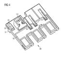
- Fig. 4 shows a movably mounted within the first side wall 2 guide slot 80.
- the switching actuators 60, 61, 62 are movably mounted.
- the guide slot 80 has a guide cam body 85 on which latching elements 84 are pivotably arranged, which serve to engage with the holding element 100 when the guide slot 80 can be held in the non-locking position NA by the holding element 100.
- a stopper member 101 is attached to the guide slot 80, which serves to engage in a screw 101 on the crank 1 when the guide slot 80 has been transferred from the non-locking position NA in the locking position AR.
- a nose 81 is arranged, which serves to block a shutter slide, not shown, of the insertion frame.
- the guide slot 80 has a guide projection 82, which serves with the Entarretierhebel 90, the in Fig. 3 and in the FIGS. 5 and 6 is shown to be in operative connection.
- the guide projection 82 has a chamfer 83, along which the Entarretierhebel 90 can be performed.
- a Entarretierhebel 90 of a drawer frame closer represents.
- the Entarretierhebel 90 is movable via a bearing 95 about a rotation axis 96 within the first side wall 2 of the insertion frame, in particular rotatably mounted.
- the Entarretierhebel 90 has a stop 92 on which a crank 1, in particular the free end of an insertable crank part 1a, can strike to rotate the Entarretierhebel 90 about its axis of rotation 96.
- the Entarretierhebel 90 has a stop arm 93 which is adapted to come into operative contact with the guide projection 82 of the guide slot 80.
- a hook 94 for a lever spring 91 is disposed on the Entarretierhebel 90, wherein the lever spring 91 serves to move the Entarretierhebel 90 from an end position END to an initial position OFF.
- the operation of Entarretierhebels 90 is described in more detail in the following figures.
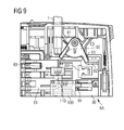
- Fig. 7 to 9 is the first side wall 2 of a drawer frame according to the invention shown in more detail in a sectional view.
- Fig. 7 is the guide slot 80 in the non-locking position NA.
- the Entarretierhebel 90 is in the situation illustrated not in operative contact with the guide slot 80 and the guide projection 82 of the guide slot 80.
- the Entarretierhebel 90 has been pivoted or rotated by the introduction of the crank 1 and the insertable crank part 1a from its original position OFF, wherein the lever spring 91 was biased. After removal of the crank 1 or the insertable crank part 1 a from the crank opening 4, the lever spring 91 provides for a return of Entarretierhebels 90 in its initial position OFF.
- the stopper member 101 of the guide cam 80 is not engaged with a screw member 101 of the crank 1, so that the crank 1 can be rotated within the first side wall 2 so as to raise or lower the drawer switchgear inserted into the drawer frame.
- To the movement of the crank 1 is the movement of the holding element 100, which is movably mounted within the first side wall 2 is coupled.
- the holding member 100 holds the guide slot 80 in the non-locking position NA.
- locking elements 84 of the guide cam body 85 of the guide slot 80 engage the retaining element 100.
- the latching elements 84 are disengaged from the holding element 100, so that in the event that the latching elements 84 are disengaged from the holding element 100, the guide slot 80 is transferred from the non-locking position NA to the locking position AR .
- a spring element can be used, which is biased in the non-locking position NA of the guide slot 80, and this applied in the direction of the locking position AR with a force.
- Fig. 8 shows a guide slot 80 in the locking position AR.
- the unlocking lever 90 is in its home position OFF.
- the stop 92 of Entarretierhebels 90 is arranged in alignment with the crank opening 4, so that when an introduction of the crank 1 in the interior of the first side wall 2, as in Fig. 9 illustrated, the crank 1, in particular the crank tip, abuts against the stop 92 of Entarretierhebels 90 in order to pivot or rotate it.
- the stop arm 93 of Entarretierhebels 90 engages with the guide projection 82 of the guide link 80. This moves the Entarretierhebel 90 by the introduction of the crank 1, in particular the insertable Crank part 1a, in the interior of the insertion frame, the guide link 80 from the locking position AR to the non-locking position NA, as in Fig. 9 shown.
- Fig. 9 has the guide slot 80 reaches the non-locking position NA, the Entarretierhebel 90 but not yet its final position. If the crank 1 or the insertable crank part 1a is further inserted into the interior of the first side wall 2 until the insertable crank part 1a is in operative contact with the installed crank part 1b, the Entarretierhebel 90 is further rotated, so that the stop arm 93 of Entarretierhebels 90 is guided past the guide projection 82 of the guide slot 80. This is possible because the Entarretierhebel 90 is not only movable in one plane, in particular rotatable, but also to this plane is formed pivotable or tiltable.
- the unlocking lever 90 or the stop arm 93 of the unlocking lever 90 can be guided past the guide projection 82 of the guide slot 80. Only then does the unlocking lever 90 reach its end position END.
- the unlocking lever 90 In order for the unlocking lever 90 to be guided back into its starting position OUT after it has been guided along the guide projection 82 and after the crank 1 or the insertable crank part 1a has been removed, the unlocking lever 90 must again be guided on the guide projection 82 of the guide slot 80 passed by.
- the unlocking lever 90 is prestressed in the end position END by the lever spring 91 and at the same time the guide projection 82 has a chamfer 83, which allows a simple sliding along the stop arm 93 on the guide projection 82. By a rotational and tilting movement of Entarretierhebels 90, this can be moved back to the starting position OFF.
- the guide slot 80 remains in the non-locking position NA, as in Fig. 9 shown.
- the crank 1 rotates by striking the tip of the crank 1 against the stop 92 of the unlocking lever 90 until the stop arm 93 engages behind the guide projection 82 of the guide link 80.
- the lever spring 91 causes the unlocking lever 90 and the stopper arm 93 of the unlocking lever 90 to again be guided past the guide projection 82 of the guide link 80 to the home position OFF take.
- this has a chamfer 83.
Landscapes
- Engineering & Computer Science (AREA)
- Power Engineering (AREA)
- Details Of Connecting Devices For Male And Female Coupling (AREA)
- Automatic Disk Changers (AREA)
- Trip Switchboards (AREA)
- Looms (AREA)
- Connector Housings Or Holding Contact Members (AREA)
Applications Claiming Priority (1)
| Application Number | Priority Date | Filing Date | Title |
|---|---|---|---|
| DE201210203469 DE102012203469A1 (de) | 2012-03-06 | 2012-03-06 | Einschubrahmen für ein elektrisches Einschubschaltgerät, insbesondere ein Einschubleistungsschalter |
Publications (3)
| Publication Number | Publication Date |
|---|---|
| EP2637270A2 true EP2637270A2 (fr) | 2013-09-11 |
| EP2637270A3 EP2637270A3 (fr) | 2014-03-26 |
| EP2637270B1 EP2637270B1 (fr) | 2015-06-24 |
Family
ID=47357940
Family Applications (1)
| Application Number | Title | Priority Date | Filing Date |
|---|---|---|---|
| EP12194548.9A Not-in-force EP2637270B1 (fr) | 2012-03-06 | 2012-11-28 | Cadre amovible pour un appareil de commutation électrique enfichable, notamment un disjoncteur enfichable |
Country Status (3)
| Country | Link |
|---|---|
| EP (1) | EP2637270B1 (fr) |
| CN (1) | CN103311055B (fr) |
| DE (1) | DE102012203469A1 (fr) |
Families Citing this family (1)
| Publication number | Priority date | Publication date | Assignee | Title |
|---|---|---|---|---|
| EP2899817B1 (fr) | 2014-01-22 | 2018-10-31 | Siemens Aktiengesellschaft | Cadre d'insertion pour dispositif de commutation électrique et dispositif d'insertion |
Family Cites Families (10)
| Publication number | Priority date | Publication date | Assignee | Title |
|---|---|---|---|---|
| IT1266549B1 (it) * | 1993-04-21 | 1997-01-09 | Sace Spa | Interruttore scatolato sezionabile |
| DE4420580C1 (de) * | 1994-06-03 | 1995-11-23 | Siemens Ag | Schaltgerät mit einer von der Schaltstellung abhängigen Einrichtung zum Ein- und Ausfahren relativ zu einem Einschubrahmen |
| US20010025773A1 (en) * | 2000-03-17 | 2001-10-04 | Rane Mahesh Jaywant | Draw out arrangement for molded case circuit breakers |
| US6472620B2 (en) * | 2000-03-17 | 2002-10-29 | Ge Power Controls France Sas | Locking arrangement for circuit breaker draw-out mechanism |
| DE20201421U1 (de) * | 2002-01-31 | 2002-07-11 | Moeller GmbH, 53115 Bonn | Anzeigevorrichtung einer Ausfahreinheit für Leistungsschalter |
| DE10250214B3 (de) * | 2002-10-24 | 2004-08-05 | Siemens Ag | Vorrichtung zur Fixierung eines Leistungsschalters in einem Einschubrahmen |
| DE102005008305A1 (de) * | 2005-02-16 | 2006-08-24 | Siemens Ag | Einschubrahmen für einen Niederspannungs- Leistungsschalter mit zwei getrennten Kulissenelementen |
| JP4641978B2 (ja) * | 2006-06-21 | 2011-03-02 | 三菱電機株式会社 | 引出形遮断器 |
| DE102007024977A1 (de) * | 2007-05-25 | 2008-11-27 | Siemens Ag | Frontbaugruppe, Geräteträger mit einer derartigen Frontbaugruppe sowie Schaltschrank mit einer Vielzahl derartiger Geräteträger |
| DE102010039934B4 (de) * | 2010-08-30 | 2017-02-02 | Siemens Aktiengesellschaft | Aufnahmemodul zur Aufnahme eines Leistungsschalters, Leistungsschaltersystem und Verfahren zum Koppeln eines Leisungsschalters mit einem Aufnahmemodul |
-
2012
- 2012-03-06 DE DE201210203469 patent/DE102012203469A1/de not_active Withdrawn
- 2012-11-28 EP EP12194548.9A patent/EP2637270B1/fr not_active Not-in-force
-
2013
- 2013-03-06 CN CN201310070766.2A patent/CN103311055B/zh not_active Expired - Fee Related
Non-Patent Citations (1)
| Title |
|---|
| None |
Also Published As
| Publication number | Publication date |
|---|---|
| EP2637270B1 (fr) | 2015-06-24 |
| EP2637270A3 (fr) | 2014-03-26 |
| CN103311055B (zh) | 2017-04-26 |
| DE102012203469A1 (de) | 2013-09-12 |
| CN103311055A (zh) | 2013-09-18 |
Similar Documents
| Publication | Publication Date | Title |
|---|---|---|
| DE69306156T2 (de) | Trennbarer Schalter mit Isolierstoffgehäuse | |
| EP1848020B1 (fr) | Coupe-circuit actionné manuellement | |
| EP2188819B1 (fr) | Interrupteur-sectionneur | |
| EP2747104B1 (fr) | Appareil de commutation multipolaire | |
| EP2975708A1 (fr) | Systeme d'adaptateur dote d'un adaptateur pour rails collecteurs et module de raccordement d'adaptateur | |
| EP2645388A2 (fr) | Dispositif de verrouillage avec interrogation de porte | |
| WO2013026518A1 (fr) | Dispositif d'entraînement pour un interrupteur à plusieurs positions | |
| WO2002087040A1 (fr) | Commutateur electrique comprenant un arbre d'entrainement et un mecanisme de verrouillage pour bloquer l'actionnement de l'arbre | |
| EP2819246B1 (fr) | Dispositif de raccordement, notamment appareil de commutation, équipé d'une borne à ressort et d'un entraînement destiné à l'actionnement de la borne à ressort | |
| EP2637270B1 (fr) | Cadre amovible pour un appareil de commutation électrique enfichable, notamment un disjoncteur enfichable | |
| DE102012203250A1 (de) | Einschubrahmen für ein elektrisches Einschubschaltgerät sowie Einheit aus einem Einschubrahmen und einem elektrischen Einschubschaltgerät | |
| DE202006015517U1 (de) | Mechanische Sicherheitsvorrichtung für Schaltgeräte | |
| DE102012203511A1 (de) | Einschubrahmen für ein elektrisches Einschubschaltgerät sowie Einheit aus Einschubrahmen und elektrischem Einschubschaltgerät | |
| AT513044B1 (de) | Vorrichtung für einen Trennschalter, insbesondere Lasttrennschalter | |
| EP2198440B1 (fr) | Interrupteur-sectionneur | |
| DE102012200662A1 (de) | Schaltvorrichtung für ein elektrisches Schaltgerät | |
| DE102012203115A1 (de) | Mechanische Türverriegelung für mindestens einen Antrieb eines elektrischen Schaltgerätes sowie Verriegelungseinheit | |
| DE102010019881A1 (de) | Kontaktmodul für eine Mittelspannungsanlage in Einschubtechnik | |
| WO2015181086A1 (fr) | Appareil de commutation à dispositif de verrouillage | |
| EP2806443B1 (fr) | Dispositif de commutation rotatif pour un appareil de commutation | |
| DE102011004968B4 (de) | Elektrischer Schalter | |
| DE102014107627B4 (de) | Schaltgerät mit Absperreinrichtung | |
| DE102013103766B4 (de) | System aus einem Steckmodul und einer Steckmodulführung für eine elektrische Schaltanlage | |
| WO2013060755A1 (fr) | Disjoncteur | |
| WO2016193039A1 (fr) | Appareil de commutation multipôle construit sous forme de barrette à coupure améliorée |
Legal Events
| Date | Code | Title | Description |
|---|---|---|---|
| PUAI | Public reference made under article 153(3) epc to a published international application that has entered the european phase |
Free format text: ORIGINAL CODE: 0009012 |
|
| AK | Designated contracting states |
Kind code of ref document: A2 Designated state(s): AL AT BE BG CH CY CZ DE DK EE ES FI FR GB GR HR HU IE IS IT LI LT LU LV MC MK MT NL NO PL PT RO RS SE SI SK SM TR |
|
| AX | Request for extension of the european patent |
Extension state: BA ME |
|
| PUAL | Search report despatched |
Free format text: ORIGINAL CODE: 0009013 |
|
| AK | Designated contracting states |
Kind code of ref document: A3 Designated state(s): AL AT BE BG CH CY CZ DE DK EE ES FI FR GB GR HR HU IE IS IT LI LT LU LV MC MK MT NL NO PL PT RO RS SE SI SK SM TR |
|
| AX | Request for extension of the european patent |
Extension state: BA ME |
|
| RIC1 | Information provided on ipc code assigned before grant |
Ipc: H02B 1/36 20060101AFI20140217BHEP Ipc: H02B 11/133 20060101ALN20140217BHEP |
|
| 17P | Request for examination filed |
Effective date: 20140919 |
|
| RBV | Designated contracting states (corrected) |
Designated state(s): AL AT BE BG CH CY CZ DE DK EE ES FI FR GB GR HR HU IE IS IT LI LT LU LV MC MK MT NL NO PL PT RO RS SE SI SK SM TR |
|
| GRAP | Despatch of communication of intention to grant a patent |
Free format text: ORIGINAL CODE: EPIDOSNIGR1 |
|
| INTG | Intention to grant announced |
Effective date: 20150123 |
|
| RIC1 | Information provided on ipc code assigned before grant |
Ipc: H02B 1/36 20060101AFI20150114BHEP Ipc: H02B 11/133 20060101ALN20150114BHEP |
|
| GRAS | Grant fee paid |
Free format text: ORIGINAL CODE: EPIDOSNIGR3 |
|
| GRAA | (expected) grant |
Free format text: ORIGINAL CODE: 0009210 |
|
| AK | Designated contracting states |
Kind code of ref document: B1 Designated state(s): AL AT BE BG CH CY CZ DE DK EE ES FI FR GB GR HR HU IE IS IT LI LT LU LV MC MK MT NL NO PL PT RO RS SE SI SK SM TR |
|
| REG | Reference to a national code |
Ref country code: GB Ref legal event code: FG4D Free format text: NOT ENGLISH |
|
| REG | Reference to a national code |
Ref country code: CH Ref legal event code: EP |
|
| REG | Reference to a national code |
Ref country code: AT Ref legal event code: REF Ref document number: 733280 Country of ref document: AT Kind code of ref document: T Effective date: 20150715 |
|
| REG | Reference to a national code |
Ref country code: IE Ref legal event code: FG4D Free format text: LANGUAGE OF EP DOCUMENT: GERMAN |
|
| REG | Reference to a national code |
Ref country code: DE Ref legal event code: R096 Ref document number: 502012003541 Country of ref document: DE |
|
| PG25 | Lapsed in a contracting state [announced via postgrant information from national office to epo] |
Ref country code: NO Free format text: LAPSE BECAUSE OF FAILURE TO SUBMIT A TRANSLATION OF THE DESCRIPTION OR TO PAY THE FEE WITHIN THE PRESCRIBED TIME-LIMIT Effective date: 20150924 Ref country code: HR Free format text: LAPSE BECAUSE OF FAILURE TO SUBMIT A TRANSLATION OF THE DESCRIPTION OR TO PAY THE FEE WITHIN THE PRESCRIBED TIME-LIMIT Effective date: 20150624 Ref country code: FI Free format text: LAPSE BECAUSE OF FAILURE TO SUBMIT A TRANSLATION OF THE DESCRIPTION OR TO PAY THE FEE WITHIN THE PRESCRIBED TIME-LIMIT Effective date: 20150624 Ref country code: LT Free format text: LAPSE BECAUSE OF FAILURE TO SUBMIT A TRANSLATION OF THE DESCRIPTION OR TO PAY THE FEE WITHIN THE PRESCRIBED TIME-LIMIT Effective date: 20150624 |
|
| REG | Reference to a national code |
Ref country code: FR Ref legal event code: PLFP Year of fee payment: 4 |
|
| REG | Reference to a national code |
Ref country code: LT Ref legal event code: MG4D |
|
| PG25 | Lapsed in a contracting state [announced via postgrant information from national office to epo] |
Ref country code: LV Free format text: LAPSE BECAUSE OF FAILURE TO SUBMIT A TRANSLATION OF THE DESCRIPTION OR TO PAY THE FEE WITHIN THE PRESCRIBED TIME-LIMIT Effective date: 20150624 Ref country code: GR Free format text: LAPSE BECAUSE OF FAILURE TO SUBMIT A TRANSLATION OF THE DESCRIPTION OR TO PAY THE FEE WITHIN THE PRESCRIBED TIME-LIMIT Effective date: 20150925 Ref country code: RS Free format text: LAPSE BECAUSE OF FAILURE TO SUBMIT A TRANSLATION OF THE DESCRIPTION OR TO PAY THE FEE WITHIN THE PRESCRIBED TIME-LIMIT Effective date: 20150624 Ref country code: BG Free format text: LAPSE BECAUSE OF FAILURE TO SUBMIT A TRANSLATION OF THE DESCRIPTION OR TO PAY THE FEE WITHIN THE PRESCRIBED TIME-LIMIT Effective date: 20150924 |
|
| REG | Reference to a national code |
Ref country code: NL Ref legal event code: MP Effective date: 20150624 |
|
| PG25 | Lapsed in a contracting state [announced via postgrant information from national office to epo] |
Ref country code: EE Free format text: LAPSE BECAUSE OF FAILURE TO SUBMIT A TRANSLATION OF THE DESCRIPTION OR TO PAY THE FEE WITHIN THE PRESCRIBED TIME-LIMIT Effective date: 20150624 |
|
| PG25 | Lapsed in a contracting state [announced via postgrant information from national office to epo] |
Ref country code: ES Free format text: LAPSE BECAUSE OF FAILURE TO SUBMIT A TRANSLATION OF THE DESCRIPTION OR TO PAY THE FEE WITHIN THE PRESCRIBED TIME-LIMIT Effective date: 20150624 Ref country code: CZ Free format text: LAPSE BECAUSE OF FAILURE TO SUBMIT A TRANSLATION OF THE DESCRIPTION OR TO PAY THE FEE WITHIN THE PRESCRIBED TIME-LIMIT Effective date: 20150624 Ref country code: IS Free format text: LAPSE BECAUSE OF FAILURE TO SUBMIT A TRANSLATION OF THE DESCRIPTION OR TO PAY THE FEE WITHIN THE PRESCRIBED TIME-LIMIT Effective date: 20151024 Ref country code: RO Free format text: LAPSE BECAUSE OF NON-PAYMENT OF DUE FEES Effective date: 20150624 Ref country code: PL Free format text: LAPSE BECAUSE OF FAILURE TO SUBMIT A TRANSLATION OF THE DESCRIPTION OR TO PAY THE FEE WITHIN THE PRESCRIBED TIME-LIMIT Effective date: 20150624 Ref country code: SK Free format text: LAPSE BECAUSE OF FAILURE TO SUBMIT A TRANSLATION OF THE DESCRIPTION OR TO PAY THE FEE WITHIN THE PRESCRIBED TIME-LIMIT Effective date: 20150624 Ref country code: PT Free format text: LAPSE BECAUSE OF FAILURE TO SUBMIT A TRANSLATION OF THE DESCRIPTION OR TO PAY THE FEE WITHIN THE PRESCRIBED TIME-LIMIT Effective date: 20151026 |
|
| REG | Reference to a national code |
Ref country code: DE Ref legal event code: R097 Ref document number: 502012003541 Country of ref document: DE |
|
| PG25 | Lapsed in a contracting state [announced via postgrant information from national office to epo] |
Ref country code: DK Free format text: LAPSE BECAUSE OF FAILURE TO SUBMIT A TRANSLATION OF THE DESCRIPTION OR TO PAY THE FEE WITHIN THE PRESCRIBED TIME-LIMIT Effective date: 20150624 |
|
| PLBE | No opposition filed within time limit |
Free format text: ORIGINAL CODE: 0009261 |
|
| STAA | Information on the status of an ep patent application or granted ep patent |
Free format text: STATUS: NO OPPOSITION FILED WITHIN TIME LIMIT |
|
| 26N | No opposition filed |
Effective date: 20160329 |
|
| PG25 | Lapsed in a contracting state [announced via postgrant information from national office to epo] |
Ref country code: LU Free format text: LAPSE BECAUSE OF FAILURE TO SUBMIT A TRANSLATION OF THE DESCRIPTION OR TO PAY THE FEE WITHIN THE PRESCRIBED TIME-LIMIT Effective date: 20151128 Ref country code: MC Free format text: LAPSE BECAUSE OF FAILURE TO SUBMIT A TRANSLATION OF THE DESCRIPTION OR TO PAY THE FEE WITHIN THE PRESCRIBED TIME-LIMIT Effective date: 20150624 |
|
| REG | Reference to a national code |
Ref country code: CH Ref legal event code: PL |
|
| PG25 | Lapsed in a contracting state [announced via postgrant information from national office to epo] |
Ref country code: CH Free format text: LAPSE BECAUSE OF NON-PAYMENT OF DUE FEES Effective date: 20151130 Ref country code: LI Free format text: LAPSE BECAUSE OF NON-PAYMENT OF DUE FEES Effective date: 20151130 |
|
| REG | Reference to a national code |
Ref country code: IE Ref legal event code: MM4A |
|
| PG25 | Lapsed in a contracting state [announced via postgrant information from national office to epo] |
Ref country code: SI Free format text: LAPSE BECAUSE OF FAILURE TO SUBMIT A TRANSLATION OF THE DESCRIPTION OR TO PAY THE FEE WITHIN THE PRESCRIBED TIME-LIMIT Effective date: 20150624 |
|
| PG25 | Lapsed in a contracting state [announced via postgrant information from national office to epo] |
Ref country code: IE Free format text: LAPSE BECAUSE OF NON-PAYMENT OF DUE FEES Effective date: 20151128 |
|
| REG | Reference to a national code |
Ref country code: FR Ref legal event code: PLFP Year of fee payment: 5 |
|
| PG25 | Lapsed in a contracting state [announced via postgrant information from national office to epo] |
Ref country code: HU Free format text: LAPSE BECAUSE OF FAILURE TO SUBMIT A TRANSLATION OF THE DESCRIPTION OR TO PAY THE FEE WITHIN THE PRESCRIBED TIME-LIMIT; INVALID AB INITIO Effective date: 20121128 Ref country code: SM Free format text: LAPSE BECAUSE OF FAILURE TO SUBMIT A TRANSLATION OF THE DESCRIPTION OR TO PAY THE FEE WITHIN THE PRESCRIBED TIME-LIMIT Effective date: 20150624 |
|
| PG25 | Lapsed in a contracting state [announced via postgrant information from national office to epo] |
Ref country code: SE Free format text: LAPSE BECAUSE OF FAILURE TO SUBMIT A TRANSLATION OF THE DESCRIPTION OR TO PAY THE FEE WITHIN THE PRESCRIBED TIME-LIMIT Effective date: 20150624 Ref country code: CY Free format text: LAPSE BECAUSE OF FAILURE TO SUBMIT A TRANSLATION OF THE DESCRIPTION OR TO PAY THE FEE WITHIN THE PRESCRIBED TIME-LIMIT Effective date: 20150624 Ref country code: NL Free format text: LAPSE BECAUSE OF FAILURE TO SUBMIT A TRANSLATION OF THE DESCRIPTION OR TO PAY THE FEE WITHIN THE PRESCRIBED TIME-LIMIT Effective date: 20150624 |
|
| GBPC | Gb: european patent ceased through non-payment of renewal fee |
Effective date: 20161128 |
|
| PG25 | Lapsed in a contracting state [announced via postgrant information from national office to epo] |
Ref country code: BE Free format text: LAPSE BECAUSE OF NON-PAYMENT OF DUE FEES Effective date: 20151130 |
|
| PG25 | Lapsed in a contracting state [announced via postgrant information from national office to epo] |
Ref country code: MT Free format text: LAPSE BECAUSE OF FAILURE TO SUBMIT A TRANSLATION OF THE DESCRIPTION OR TO PAY THE FEE WITHIN THE PRESCRIBED TIME-LIMIT Effective date: 20150624 |
|
| REG | Reference to a national code |
Ref country code: FR Ref legal event code: PLFP Year of fee payment: 6 |
|
| PG25 | Lapsed in a contracting state [announced via postgrant information from national office to epo] |
Ref country code: GB Free format text: LAPSE BECAUSE OF NON-PAYMENT OF DUE FEES Effective date: 20161128 |
|
| PG25 | Lapsed in a contracting state [announced via postgrant information from national office to epo] |
Ref country code: TR Free format text: LAPSE BECAUSE OF FAILURE TO SUBMIT A TRANSLATION OF THE DESCRIPTION OR TO PAY THE FEE WITHIN THE PRESCRIBED TIME-LIMIT Effective date: 20150624 Ref country code: MK Free format text: LAPSE BECAUSE OF FAILURE TO SUBMIT A TRANSLATION OF THE DESCRIPTION OR TO PAY THE FEE WITHIN THE PRESCRIBED TIME-LIMIT Effective date: 20150624 |
|
| PG25 | Lapsed in a contracting state [announced via postgrant information from national office to epo] |
Ref country code: AL Free format text: LAPSE BECAUSE OF FAILURE TO SUBMIT A TRANSLATION OF THE DESCRIPTION OR TO PAY THE FEE WITHIN THE PRESCRIBED TIME-LIMIT Effective date: 20150624 |
|
| REG | Reference to a national code |
Ref country code: AT Ref legal event code: MM01 Ref document number: 733280 Country of ref document: AT Kind code of ref document: T Effective date: 20171128 |
|
| PG25 | Lapsed in a contracting state [announced via postgrant information from national office to epo] |
Ref country code: AT Free format text: LAPSE BECAUSE OF NON-PAYMENT OF DUE FEES Effective date: 20171128 |
|
| PGFP | Annual fee paid to national office [announced via postgrant information from national office to epo] |
Ref country code: FR Payment date: 20211119 Year of fee payment: 10 |
|
| PGFP | Annual fee paid to national office [announced via postgrant information from national office to epo] |
Ref country code: IT Payment date: 20211122 Year of fee payment: 10 |
|
| PGFP | Annual fee paid to national office [announced via postgrant information from national office to epo] |
Ref country code: DE Payment date: 20220119 Year of fee payment: 10 |
|
| REG | Reference to a national code |
Ref country code: DE Ref legal event code: R119 Ref document number: 502012003541 Country of ref document: DE |
|
| PG25 | Lapsed in a contracting state [announced via postgrant information from national office to epo] |
Ref country code: IT Free format text: LAPSE BECAUSE OF NON-PAYMENT OF DUE FEES Effective date: 20221128 Ref country code: DE Free format text: LAPSE BECAUSE OF NON-PAYMENT OF DUE FEES Effective date: 20230601 |
|
| PG25 | Lapsed in a contracting state [announced via postgrant information from national office to epo] |
Ref country code: FR Free format text: LAPSE BECAUSE OF NON-PAYMENT OF DUE FEES Effective date: 20221130 |