EP2636348A2 - Vacuum cleaner and vacuum cleaner system - Google Patents
Vacuum cleaner and vacuum cleaner system Download PDFInfo
- Publication number
- EP2636348A2 EP2636348A2 EP13157526.8A EP13157526A EP2636348A2 EP 2636348 A2 EP2636348 A2 EP 2636348A2 EP 13157526 A EP13157526 A EP 13157526A EP 2636348 A2 EP2636348 A2 EP 2636348A2
- Authority
- EP
- European Patent Office
- Prior art keywords
- housing
- vacuum cleaner
- filter bag
- helical
- filter
- Prior art date
- Legal status (The legal status is an assumption and is not a legal conclusion. Google has not performed a legal analysis and makes no representation as to the accuracy of the status listed.)
- Granted
Links
Images


Classifications
-
- A—HUMAN NECESSITIES
- A47—FURNITURE; DOMESTIC ARTICLES OR APPLIANCES; COFFEE MILLS; SPICE MILLS; SUCTION CLEANERS IN GENERAL
- A47L—DOMESTIC WASHING OR CLEANING; SUCTION CLEANERS IN GENERAL
- A47L5/00—Structural features of suction cleaners
- A47L5/12—Structural features of suction cleaners with power-driven air-pumps or air-compressors, e.g. driven by motor vehicle engine vacuum
- A47L5/22—Structural features of suction cleaners with power-driven air-pumps or air-compressors, e.g. driven by motor vehicle engine vacuum with rotary fans
- A47L5/28—Suction cleaners with handles and nozzles fixed on the casings, e.g. wheeled suction cleaners with steering handle
-
- A—HUMAN NECESSITIES
- A47—FURNITURE; DOMESTIC ARTICLES OR APPLIANCES; COFFEE MILLS; SPICE MILLS; SUCTION CLEANERS IN GENERAL
- A47L—DOMESTIC WASHING OR CLEANING; SUCTION CLEANERS IN GENERAL
- A47L5/00—Structural features of suction cleaners
- A47L5/12—Structural features of suction cleaners with power-driven air-pumps or air-compressors, e.g. driven by motor vehicle engine vacuum
- A47L5/22—Structural features of suction cleaners with power-driven air-pumps or air-compressors, e.g. driven by motor vehicle engine vacuum with rotary fans
- A47L5/225—Convertible suction cleaners, i.e. convertible between different types thereof, e.g. from upright suction cleaners to sledge-type suction cleaners
-
- A—HUMAN NECESSITIES
- A47—FURNITURE; DOMESTIC ARTICLES OR APPLIANCES; COFFEE MILLS; SPICE MILLS; SUCTION CLEANERS IN GENERAL
- A47L—DOMESTIC WASHING OR CLEANING; SUCTION CLEANERS IN GENERAL
- A47L9/00—Details or accessories of suction cleaners, e.g. mechanical means for controlling the suction or for effecting pulsating action; Storing devices specially adapted to suction cleaners or parts thereof; Carrying-vehicles specially adapted for suction cleaners
- A47L9/10—Filters; Dust separators; Dust removal; Automatic exchange of filters
- A47L9/12—Dry filters
- A47L9/122—Dry filters flat
-
- A—HUMAN NECESSITIES
- A47—FURNITURE; DOMESTIC ARTICLES OR APPLIANCES; COFFEE MILLS; SPICE MILLS; SUCTION CLEANERS IN GENERAL
- A47L—DOMESTIC WASHING OR CLEANING; SUCTION CLEANERS IN GENERAL
- A47L9/00—Details or accessories of suction cleaners, e.g. mechanical means for controlling the suction or for effecting pulsating action; Storing devices specially adapted to suction cleaners or parts thereof; Carrying-vehicles specially adapted for suction cleaners
- A47L9/10—Filters; Dust separators; Dust removal; Automatic exchange of filters
- A47L9/14—Bags or the like; Rigid filtering receptacles; Attachment of, or closures for, bags or receptacles
- A47L9/1427—Means for mounting or attaching bags or filtering receptacles in suction cleaners; Adapters
-
- A—HUMAN NECESSITIES
- A47—FURNITURE; DOMESTIC ARTICLES OR APPLIANCES; COFFEE MILLS; SPICE MILLS; SUCTION CLEANERS IN GENERAL
- A47L—DOMESTIC WASHING OR CLEANING; SUCTION CLEANERS IN GENERAL
- A47L9/00—Details or accessories of suction cleaners, e.g. mechanical means for controlling the suction or for effecting pulsating action; Storing devices specially adapted to suction cleaners or parts thereof; Carrying-vehicles specially adapted for suction cleaners
- A47L9/10—Filters; Dust separators; Dust removal; Automatic exchange of filters
- A47L9/14—Bags or the like; Rigid filtering receptacles; Attachment of, or closures for, bags or receptacles
- A47L9/1481—Means for removing bags in suction cleaners, e.g. ejecting means; Means for exchanging bags
-
- A—HUMAN NECESSITIES
- A47—FURNITURE; DOMESTIC ARTICLES OR APPLIANCES; COFFEE MILLS; SPICE MILLS; SUCTION CLEANERS IN GENERAL
- A47L—DOMESTIC WASHING OR CLEANING; SUCTION CLEANERS IN GENERAL
- A47L9/00—Details or accessories of suction cleaners, e.g. mechanical means for controlling the suction or for effecting pulsating action; Storing devices specially adapted to suction cleaners or parts thereof; Carrying-vehicles specially adapted for suction cleaners
- A47L9/10—Filters; Dust separators; Dust removal; Automatic exchange of filters
- A47L9/16—Arrangement or disposition of cyclones or other devices with centrifugal action
- A47L9/1608—Cyclonic chamber constructions
-
- A—HUMAN NECESSITIES
- A47—FURNITURE; DOMESTIC ARTICLES OR APPLIANCES; COFFEE MILLS; SPICE MILLS; SUCTION CLEANERS IN GENERAL
- A47L—DOMESTIC WASHING OR CLEANING; SUCTION CLEANERS IN GENERAL
- A47L9/00—Details or accessories of suction cleaners, e.g. mechanical means for controlling the suction or for effecting pulsating action; Storing devices specially adapted to suction cleaners or parts thereof; Carrying-vehicles specially adapted for suction cleaners
- A47L9/10—Filters; Dust separators; Dust removal; Automatic exchange of filters
- A47L9/16—Arrangement or disposition of cyclones or other devices with centrifugal action
- A47L9/165—Construction of inlets
-
- A—HUMAN NECESSITIES
- A47—FURNITURE; DOMESTIC ARTICLES OR APPLIANCES; COFFEE MILLS; SPICE MILLS; SUCTION CLEANERS IN GENERAL
- A47L—DOMESTIC WASHING OR CLEANING; SUCTION CLEANERS IN GENERAL
- A47L9/00—Details or accessories of suction cleaners, e.g. mechanical means for controlling the suction or for effecting pulsating action; Storing devices specially adapted to suction cleaners or parts thereof; Carrying-vehicles specially adapted for suction cleaners
- A47L9/10—Filters; Dust separators; Dust removal; Automatic exchange of filters
- A47L9/16—Arrangement or disposition of cyclones or other devices with centrifugal action
- A47L9/1691—Mounting or coupling means for cyclonic chamber or dust receptacles
-
- A—HUMAN NECESSITIES
- A47—FURNITURE; DOMESTIC ARTICLES OR APPLIANCES; COFFEE MILLS; SPICE MILLS; SUCTION CLEANERS IN GENERAL
- A47L—DOMESTIC WASHING OR CLEANING; SUCTION CLEANERS IN GENERAL
- A47L9/00—Details or accessories of suction cleaners, e.g. mechanical means for controlling the suction or for effecting pulsating action; Storing devices specially adapted to suction cleaners or parts thereof; Carrying-vehicles specially adapted for suction cleaners
- A47L9/10—Filters; Dust separators; Dust removal; Automatic exchange of filters
- A47L9/19—Means for monitoring filtering operation
-
- A—HUMAN NECESSITIES
- A47—FURNITURE; DOMESTIC ARTICLES OR APPLIANCES; COFFEE MILLS; SPICE MILLS; SUCTION CLEANERS IN GENERAL
- A47L—DOMESTIC WASHING OR CLEANING; SUCTION CLEANERS IN GENERAL
- A47L9/00—Details or accessories of suction cleaners, e.g. mechanical means for controlling the suction or for effecting pulsating action; Storing devices specially adapted to suction cleaners or parts thereof; Carrying-vehicles specially adapted for suction cleaners
- A47L9/32—Handles
- A47L9/325—Handles for wheeled suction cleaners with steering handle
Definitions
- Upright vacuum cleaners employ a variety of dirt separators to remove dirt and debris from a working air stream.
- Some upright vacuum cleaners employ cyclone separators.
- Some cyclone separators use one or more frusto-conical-shaped separator(s) and others use high-speed rotational motion of the air/dirt to separate the dirt by centrifugal force.
- working air enters and exits at an upper portion of the cyclone separator as the bottom portion of the cyclone separator is used to collect debris.
- the working air Before exiting the cyclone separator, the working air may flow through an exhaust grill.
- the exhaust grill can have perforations, holes, vanes, or louvers defining openings through which air may pass.
- Upright vacuum cleaners can also employ filter bag separators.
- working air is either forced through or drawn through an air permeable filter bag leaving the debris entrained in the working air path inside the filter bag.
- a vacuum cleaner comprises a body having a suction nozzle, a dirt separating and collecting system provided on the body comprising a housing defining a chamber with an air inlet and an air outlet, a filter bag removably mounted within the chamber to separate and collect dirt from a working air stream passing from the air inlet to the air outlet, and a helical inlet guide disposed within the housing and directing the working air stream from the air inlet to the filter bag along a helical pathway, and a suction source fluidly connected to the suction nozzle and to the air inlet for establishing and maintaining a dirt-containing working airstream from the suction nozzle to the chamber, wherein the housing is at least partially transparent to permit the helical inlet guide to be viewed from the exterior of the vacuum cleaner.
- the invention relates to vacuum cleaners and vacuum cleaner systems.
- the invention relates to a vacuum cleaner system that can receive different filter modules.
- the invention relates to an improved filter bag inlet for a dirt separating and collecting system.
- the terms "upper,” “lower,” “right,” “left,” “rear,” “front,” “vertical,” “horizontal,” and derivatives thereof shall relate to the invention as oriented in FIG. 1 from the perspective of a user behind the vacuum cleaner, which defines the rear of the vacuum cleaner.
- the invention may assume various alternative orientations, except where expressly specified to the contrary.
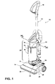
- an upright vacuum cleaner 10 comprises an upright handle assembly 12 pivotally mounted to a foot assembly 14.
- the handle assembly 12 further comprises a primary support section 16 with a grip 18 on one end to facilitate movement by a user.
- a motor cavity 20 is formed at an opposite end of the handle assembly 12 to contain a conventional suction source such as a vacuum fan/motor assembly (not shown) oriented transversely therein.
- a filter housing 22 is formed above the motor cavity 20 and is in fluid communication with the vacuum fan/motor assembly.
- the handle assembly 12 pivots relative to the foot assembly 14 through a pivot axis that is coaxial with a motor shaft (not shown) associated with the vacuum fan/motor assembly.
- a mounting section 24 on the primary support section 16 of the handle assembly 12 receives a dirt separating and collecting system or dirt separation module assembly 26 according to a first embodiment of the invention.
- the foot assembly 14 comprises a housing 28 with a suction nozzle 30 formed at a lower surface thereof and that is in fluid communication with the vacuum fan/motor assembly (not shown) within the motor cavity 20. While not shown, an agitator can be positioned within the housing 28 adjacent to the suction nozzle 30 and operably connected to a dedicated agitator motor, or to the vacuum fan/motor assembly within the motor cavity 20 via a stretch belt or other suitable coupling.
- Rear wheels 32 are secured to a rearward portion of the foot assembly 14 and a pair of support wheels (not shown) are secured to a forward portion of the foot assembly 14 for moving the foot assembly 14 over a surface to be cleaned.
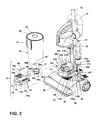
- the dirt separation module assembly 26 separates contaminants from a dirt-containing working airstream and comprises a cover 34, a helical inlet guide 36, an air permeable filter bag assembly 38, and a lower housing 40.
- the cover 34 can be transparent or alternatively contain a transparent portion or window that allows line of sight visibility to the helical inlet guide 36 contained therein.
- the lower housing 40 can be opaque to hide the filter bag assembly 38 from view during normal operation of the vacuum cleaner 10.
- the cover 34 and lower housing 40 can collectively define a housing having a chamber in which the helical inlet guide 36 and the filter bag assembly 38 are received.
- the cover 34 can be stationary, in that is not intended to be removed from the vacuum cleaner 10 by the user.
- the lower housing 40 can be removable, in that it is easily removed from the vacuum cleaner 10 by the user. Thus, the lower housing 40 can be removed from the vacuum cleaner 10 without removing the cover 34. This permits the filter bag assembly 38 to be selectively removed from the lower housing 40 without needing to remove the helical inlet guide 36 from the vacuum cleaner 10.
- the cover 34 comprises a working air inlet 42 in fluid communication with the suction nozzle 30 of the foot assembly 14.
- a locking receiver 44 is centrally located on an upper surface of the cover 34 and is configured to receive an upper surface of the helical inlet guide 36.
- a cover sealing surface 46 is located at a lower portion of the cover 34 and engages with a mating surface on the housing 40.
- the helical inlet guide 36 comprises a generally spiral or helical ramp 48 around a center support structure 50 and terminates in an inlet guide outlet aperture 52.
- An upper portion of the center support structure 50 comprises an opposed pair of locking tabs 54 that interface with the locking receiver 44 ( FIG. 4 ) to removably retain the inlet guide 36 to the cover 34.
- a mating surface 56 is located at a lower portion of the center support structure 50.
- a downwardly depending lip 57 can be provided on the outer edge of the helical ramp 48. The lip 57 can help prevent dirt from leaking through the gap between the helical ramp 48 and the inner wall of the cover 34. The lip 57 can optionally be configured to seal against the sidewall of the cover 34.
- the filter bag assembly 38 comprises a rigid inlet guide interface structure 58 to which a permeable filter bag 60 is attached using a bonding means such as adhesives, stitching, staples, or other suitable means.
- the filter bag 60 may be flexible.
- a filter bag assembly working air inlet 62 is centrally located in the inlet guide interface structure 58 and is in fluid communication with the lower mating surface 56 of the inlet guide 36 ( FIG. 5 ).
- the interface structure 58 can comprise a release tab 63 which facilitates removal of the filter bag assembly 38 from the housing 40. When the housing 40 is separated from the vacuum cleaner 10, a user can grip the release tab 63 to lift the entire filter bag assembly 38 from the housing 40.
- the inlet guide interface structure 58 mounted to the top edge of the housing 40 and thereby forming the sealing interface to the cover 34 when the filter bag assembly 38 is installed in the use position
- the interface structure 58 can be mounted within the housing 40, below the upper edge thereof, so that the upper edge of the housing 40 seals against the cover 34 during use.
- the inlet guide interface structure 58 can be omitted altogether and the top of the filter bag 60 can be held between the housing 40 and the cover 34 and the upper edge of the housing can seal against the cover 34.
- a gasket 64 can be associated with either the inlet guide interface structure 58 or the lower mating surface 56 of the inlet guide 36 to fluidly seal the filter bag assembly 38 to the helical inlet guide 36.
- the gasket 56 is removably attached to the inlet guide 36.
- the housing 40 further comprises a generally cup-shaped structure having a bottom wall 76 and a side wall 78 extending upwardly from the bottom wall to an open top forming a sealing surface 66 at an upper surface of the side wall.
- a centrally located housing outlet grill 68 is located on the bottom wall 76 of the housing 40 and is in fluid communication with the permeable filter bag assembly 38 ( FIG. 3 ).
- the filter bag assembly 38 is configured to removably insert in the interior of the housing 40 as will be described in more detail below.
- a filter bag housing grip 70 is located on an outer surface of the side wall 78.
- the housing outlet grill 68 is also in fluid communication with a motor inlet 16b located in the handle assembly 12 ( FIG. 10 ).
- the housing 40 is removably retained by a latch assembly 74 in the handle assembly 12 ( FIG. 2 ).
- the housing 40 may further include one or more vertical rib(s) 86 adjacent the bottom wall 76 and extending upwardly along the interior of the side wall 78.
- the rib(s) 86 may extend radially away from the side wall 78 toward the center of the housing 40, and function to support the bag assembly 38 and maintain a gap between the bag assembly 38 and the side wall 78 of the housing 40 during use.
- the ribs (86) are L-shaped, such that they also extend away from the bottom wall 76, thereby also maintaining the gap between the bag assembly 38 and the bottom wall 76 of the housing 40 during use.
- the gap forms a portion of the working air path between the bag 30 and the outlet 68.
- the ribs 86 can also support a portion the inlet guide interface structure 58.
- the dirt separation module assembly 26 can be provided with a pre-motor filter assembly 80.
- the pre-motor filter assembly 80 can be provided within the housing 40 and may be positioned upstream of the housing outlet grill 68.
- the pre-motor filter assembly 80 includes a pre-motor filter 82 comprising a conventional porous foam or non-woven filter material which covers the housing outlet grill 68, and a pre-motor filter frame 84 which covers and retains the pre-motor filter 82 within the housing 40.
- the filter frame 84 may be at least partially open to allow working air to pass through the filter frame 84 and filter 82.
- the filter frame 84 and filter 82 may be removable, in order to clean or replace the pre-motor filter.
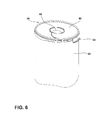
- FIG. 8 shows a cross section of the dirt separation module assembly 26, with air flow through the assembly 26 depicted with arrows.
- Working air containing debris removed from the surface to be cleaned at the suction nozzle 30 ( FIG. 1 ) is drawn into the working air inlet 42.
- Working air travels around and down the inlet guide center support structure 50 underneath the helical ramp 48 and down to the inlet guide outlet aperture 52 where it enters the filter bag assembly 38 through the filter bag working air inlet 62.
- Dirty air enters the interior of the filter bag assembly 38 where debris 72 is captured by the filter bag material 60.
- Filtered air passes through the filter bag material 60 and exits the housing 40 through the housing outlet grill 68 to enter the suction fan inlet 16b ( FIG. 10 ).
- the helical ramp 48 in combination with a clear cover 34 allows the user to see dirt entering the filter bag assembly 38 during use.
- the helical inlet guide 36 and the filter bag assembly 38 are one example of a filter module which can be removably mounted within the chamber of the dirt separation module assembly 26 to separate dirt from a working air stream passing from the air inlet 42 to the air outlet 68.
- Other filter modules can be removably mounted within the chamber.
- the filter module shown in FIG. 8 is an example of a bagged filter module.
- FIG. 9 shows one example of a bagless filter module.
- the vacuum cleaner 10 can be part of a vacuum cleaner system having multiple, interchangeable filter modules.
- the filter modules can be alternatively mounted within the chamber and fluidly coupled with the air inlet 42 and the air outlet 68 to separate dirt from a working air stream.
- an attachment mechanism can be provided for removably attaching the filter module to the dirt separation module assembly 26.
- the attachment mechanism is a bayonet mount that includes a female portion in the form of the locking receiver 44 located on the cover 34 and a male portion in the form of the locking tabs 54 located on a portion of the filter module.
- the locking tabs 54 are inserted into the locking receiver 44 and rotated 1 ⁇ 4 turn to removably retain at least a portion of the filter module on the cover 34.
- the male and female portions of the bayonet mount can be reversed on the filter module and cover 34.
- Other types of attachment mechanisms can be used, including threaded attachments, press-fits, snaps, clips, etc.
- FIG. 9 is a cross-sectional view of a second configuration of the dirt separation module assembly 26.
- the chamber defined by the cover and lower housing 40 receives a bagless filter module instead of the bagged filter module shown in FIG. 8 .
- the bagless filter module is a cyclonic filter module having a single separation stage.
- Other bagless filter modules are possible, and include a multi-stage cyclonic separator or a non-cyclonic, bagless separator.
- the bagless filter module illustrated herein can include a removable standpipe 200 and a centrifugal separator exhaust grill 210.
- the lower housing 40 can optionally be fitted with the removable standpipe 200 in place of the filter bag assembly 38 ( FIG.
- the standpipe 200 is a rigid tubular structure with a lower end 202 and an upper end 204.
- the lower end 202 of the standpipe 200 is removably press fit to the housing outlet grill 68 inside the housing 40.
- the standpipe 200 when installed, is flush or slightly below the housing 40 sealing surface 66 to allow the housing 40 to be removed from the handle 12, while leaving the cover 34 on the handle 12.
- the standpipe upper end 204 is sized to mate with a gasket 208 on a lower end of the centrifugal separator exhaust grill 210.
- the exhaust grill 210 comprises openings 212 through which air may pass into the standpipe 200, and a separator plate 206 to separate the cyclonic separation region 214 from the dirt collecting region 216.
- a suitable grill 210 is shown in U.S. Pat. No. 7,708,789 to Fester , which is incorporated herein by reference in its entirety.
- Other suitable grills 210 may have perforations, holes, vanes, or louvers defining the openings 212.
- the exhaust grill 210 further includes an opposed pair of locking tabs 54 that interface with the locking receiver 44 ( FIG. 4 ) to removably retain the exhaust grill 210 on the cover 34.
- the rib(s) 86 in the housing 40 function to inhibit the vacillation of the debris deposited in the dirt collecting region 216 of the housing 40, thereby disrupting the currents that would tend to carry smaller dirt particles upwardly and back into the working air flow.
- the rib(s) 86 can also deflect dirt particles within the dirt collecting region 216 to further encourage agglomeration of the dirt particles within the housing 40.
- the vacuum cleaner 10 can easily be changed from a bagged separator, shown in FIG. 8 to a bagless separator, shown in FIG. 9 , by simply removing the filter bag assembly 38 from the housing 40, inserting the standpipe 200 on the housing outlet grill 68, removing the helical inlet guide 36 from the cover 34 and replacing the helical inlet guide 36 with the exhaust grill 210.
- the retention latch assembly 74 selectively raises and lowers the housing 40.
- Any number of known retention latches are suitable, including those disclosed in U.S. Pat. No. 7,191,490 to Lee et al ., U.S. Pat. No. 6,732,406 to Oh , U.S. Pat. No. 6,735,816 to Oh et al ., and U.S. Pat. No. 6,991,667 to Yang et al ., incorporated herein by reference in their entirety.
- Another suitable description is found in U.S. Pat. No. 8,032,983 to Griffith et al ., which is incorporated herein by reference in its entirety.
- the housing 40 is removably retained on the handle assembly 12 by the latch assembly 74.
- the housing outlet grill 68 fluidly communicates with the motor inlet 16b within the handle assembly 12, through aligned housing outlet grill 68 and further through a bore 60c of an annular seal member 61 mounted on a housing base 100 on the handle 12.
- the housing outlet grill 68 rests on an upper sealing face 60a of the seal member 61.
- a lower end 60e of seal member 61 is in fluid communication with the motor inlet 16b.
- the seal member 61 is trapped for up-and-down movement on a collar structure 110, 112 around the motor inlet 16b.
- a generally U-shaped slide lock member 71 is mounted to slide generally horizontally in and out on the housing base 100 in a substantially straight path, in sliding contact with portions of the trapped seal member 61 to cam the seal member up and down.
- the slide lock member 71 is pulled out away from the handle 12 (forward) allowing the housing 40 to drop down below the cover sealing surface 46.
- the user grasps the housing 40 by the grip 70 and pulls the housing 40 out of the handle 12.
- the user then inserts the filter bag assembly 38 inside of the housing 40 so that the inlet interface structure 58 rests on a lip (not shown) adjacent the housing 40 sealing surface 66.
- the inlet guide 36 is inserted into the cover 34 from below, and the locking tabs 54 are inserted into the locking receiver 44 and rotated 1 ⁇ 4 turn to removably retain the inlet guide 36 on the cover 34.
- the housing 40 with the filter bag assembly 38 is then inserted into the handle 12 under the cover 34 and on the latch assembly 74.
- the user pushes in the slide lock member 71 (rearward), raising the housing 40 until the upper sealing surface 66 sealingly mates with the lower cover sealing surface 46.
- the gasket 64 on the lower mating surface 56 of the inlet guide 36 seals the filter bag working air inlet 62 to provide working air flow through the dirt separation module assembly 26 as illustrated in FIG. 8 .
- the clear cover 34 allows the user to see dirty air entering the filter bag assembly 38 around the helix inlet guide 38.
- the user can employ the optional standpipe 200 and grill 210 to convert the vacuum cleaner 10 to a conventional bagless unit.
- a user pulls the slide lock member 71 out away from the handle 12 (forward) allowing the housing 40 to drop down below the cover sealing surface 46.
- the user grasps the housing 40 by the grip 70 and pulls the housing 40 out of the handle 12.
- the filter bag assembly 38 is removed from the housing 40.
- the user inserts the standpipe 200 over the housing 40 outlet 60.
- the user then reaches up inside the cover 34, grasps the helical inlet guide 36, rotates the inlet guide 361 ⁇ 4 turn, and removes the helical inlet guide 36 from the top of the cover 34.
- the user then inserts the exhaust grill 210 in the cover 34 in reverse order.
- the housing 40 with the standpipe 200 is inserted into the handle 12 under the cover 34 and on the latch assembly 74.
- the user pushes in the slide lock member 71 (rearward), raising the housing 40 until the upper sealing surface 66 sealingly mates with the lower cover sealing surface 46.
- the upper end 204 of the standpipe 200 sealingly engages the gasket 208 on the bagless cyclone exhaust grill 206 to provide working air flow through the dirt separation module assembly 26 as illustrated in FIG. 10 .
Abstract
Description
- This application claims the benefit of
U.S. Provisional Patent Application No. 61/608,288, filed March 8, 2012 - Upright vacuum cleaners employ a variety of dirt separators to remove dirt and debris from a working air stream. Some upright vacuum cleaners employ cyclone separators. Some cyclone separators use one or more frusto-conical-shaped separator(s) and others use high-speed rotational motion of the air/dirt to separate the dirt by centrifugal force. Typically, working air enters and exits at an upper portion of the cyclone separator as the bottom portion of the cyclone separator is used to collect debris. Before exiting the cyclone separator, the working air may flow through an exhaust grill. The exhaust grill can have perforations, holes, vanes, or louvers defining openings through which air may pass.
- Upright vacuum cleaners can also employ filter bag separators. Typically, working air is either forced through or drawn through an air permeable filter bag leaving the debris entrained in the working air path inside the filter bag.
- According to one aspect of the invention, a vacuum cleaner comprises a body having a suction nozzle, a dirt separating and collecting system provided on the body comprising a housing defining a chamber with an air inlet and an air outlet, a filter bag removably mounted within the chamber to separate and collect dirt from a working air stream passing from the air inlet to the air outlet, and a helical inlet guide disposed within the housing and directing the working air stream from the air inlet to the filter bag along a helical pathway, and a suction source fluidly connected to the suction nozzle and to the air inlet for establishing and maintaining a dirt-containing working airstream from the suction nozzle to the chamber, wherein the housing is at least partially transparent to permit the helical inlet guide to be viewed from the exterior of the vacuum cleaner.
- In the drawings:
-
FIG. 1 is a perspective view of a vacuum cleaner having a dirt separation module assembly according to a first embodiment of the invention. -
FIG. 2 is a partial exploded perspective view of the dirt separation module ofFIG. 1 . -
FIG. 3 is an exploded perspective view of the dirt separation module assembly ofFIG. 1 . -
FIG. 4 is a perspective view of a cover of the dirt separation module ofFIG. 1 . -
FIG. 5 is a perspective view of an inlet guide of the dirt separation module ofFIG. 1 . -
FIG. 6 is a perspective view of a filter bag assembly of the dirt separation module ofFIG. 1 . -
FIG. 7 is a perspective view of a filter bag housing of the dirt separation module ofFIG. 1 . -
FIG. 8 is a cross-sectional view of a first bagged embodiment of the dirt separation module assembly taken through line VIII-VIII ofFIG. 1 showing the flow path of working air through the dirt separation module assembly. -
FIG. 9 is a cross-sectional view of a second, bagless configuration of the dirt separation module assembly ofFIG. 1 . -
FIG. 10 is a perspective view of a filter bag housing latch assembly of the vacuum cleaner ofFIG. 1 . - The invention relates to vacuum cleaners and vacuum cleaner systems. In one of its aspects, the invention relates to a vacuum cleaner system that can receive different filter modules. In another aspect, the invention relates to an improved filter bag inlet for a dirt separating and collecting system. For purposes of description related to the figures, the terms "upper," "lower," "right," "left," "rear," "front," "vertical," "horizontal," and derivatives thereof shall relate to the invention as oriented in
FIG. 1 from the perspective of a user behind the vacuum cleaner, which defines the rear of the vacuum cleaner. However, it is to be understood that the invention may assume various alternative orientations, except where expressly specified to the contrary. It is also to be understood that the specific devices and processes illustrated in the attached drawings, and described in the following specification are simply exemplary embodiments of the inventive concepts defined in the appended claims. Hence, specific dimensions and other physical characteristics relating to the embodiments disclosed herein are not to be considered as limiting, unless the claims expressly state otherwise. - Referring to the drawings, and in particular to
FIG. 1 , anupright vacuum cleaner 10 comprises anupright handle assembly 12 pivotally mounted to afoot assembly 14. Thehandle assembly 12 further comprises aprimary support section 16 with agrip 18 on one end to facilitate movement by a user. Amotor cavity 20 is formed at an opposite end of thehandle assembly 12 to contain a conventional suction source such as a vacuum fan/motor assembly (not shown) oriented transversely therein. Afilter housing 22 is formed above themotor cavity 20 and is in fluid communication with the vacuum fan/motor assembly. Thehandle assembly 12 pivots relative to thefoot assembly 14 through a pivot axis that is coaxial with a motor shaft (not shown) associated with the vacuum fan/motor assembly. A mounting section 24 on theprimary support section 16 of thehandle assembly 12 receives a dirt separating and collecting system or dirtseparation module assembly 26 according to a first embodiment of the invention. - The
foot assembly 14 comprises ahousing 28 with asuction nozzle 30 formed at a lower surface thereof and that is in fluid communication with the vacuum fan/motor assembly (not shown) within themotor cavity 20. While not shown, an agitator can be positioned within thehousing 28 adjacent to thesuction nozzle 30 and operably connected to a dedicated agitator motor, or to the vacuum fan/motor assembly within themotor cavity 20 via a stretch belt or other suitable coupling. Rear wheels 32 are secured to a rearward portion of thefoot assembly 14 and a pair of support wheels (not shown) are secured to a forward portion of thefoot assembly 14 for moving thefoot assembly 14 over a surface to be cleaned. - Referring to
FIGS.1 ,2 and3 , the dirtseparation module assembly 26 separates contaminants from a dirt-containing working airstream and comprises acover 34, ahelical inlet guide 36, an air permeablefilter bag assembly 38, and alower housing 40. Thecover 34 can be transparent or alternatively contain a transparent portion or window that allows line of sight visibility to thehelical inlet guide 36 contained therein. Thelower housing 40 can be opaque to hide thefilter bag assembly 38 from view during normal operation of thevacuum cleaner 10. Thecover 34 andlower housing 40 can collectively define a housing having a chamber in which thehelical inlet guide 36 and thefilter bag assembly 38 are received. Thecover 34 can be stationary, in that is not intended to be removed from thevacuum cleaner 10 by the user. Thelower housing 40 can be removable, in that it is easily removed from thevacuum cleaner 10 by the user. Thus, thelower housing 40 can be removed from thevacuum cleaner 10 without removing thecover 34. This permits thefilter bag assembly 38 to be selectively removed from thelower housing 40 without needing to remove thehelical inlet guide 36 from thevacuum cleaner 10. - Referring to
FIGS. 1 and4 , thecover 34 comprises a workingair inlet 42 in fluid communication with thesuction nozzle 30 of thefoot assembly 14. Alocking receiver 44 is centrally located on an upper surface of thecover 34 and is configured to receive an upper surface of thehelical inlet guide 36. Acover sealing surface 46 is located at a lower portion of thecover 34 and engages with a mating surface on thehousing 40. - Referring to
FIG. 5 , thehelical inlet guide 36 comprises a generally spiral orhelical ramp 48 around acenter support structure 50 and terminates in an inletguide outlet aperture 52. An upper portion of thecenter support structure 50 comprises an opposed pair oflocking tabs 54 that interface with the locking receiver 44 (FIG. 4 ) to removably retain theinlet guide 36 to thecover 34. Amating surface 56 is located at a lower portion of thecenter support structure 50. Optionally, a downwardly dependinglip 57 can be provided on the outer edge of thehelical ramp 48. Thelip 57 can help prevent dirt from leaking through the gap between thehelical ramp 48 and the inner wall of thecover 34. Thelip 57 can optionally be configured to seal against the sidewall of thecover 34. - Referring to
FIG. 6 , thefilter bag assembly 38 comprises a rigid inletguide interface structure 58 to which apermeable filter bag 60 is attached using a bonding means such as adhesives, stitching, staples, or other suitable means. Thefilter bag 60 may be flexible. A filter bag assembly workingair inlet 62 is centrally located in the inletguide interface structure 58 and is in fluid communication with thelower mating surface 56 of the inlet guide 36 (FIG. 5 ). Optionally, theinterface structure 58 can comprise arelease tab 63 which facilitates removal of thefilter bag assembly 38 from thehousing 40. When thehousing 40 is separated from thevacuum cleaner 10, a user can grip therelease tab 63 to lift the entirefilter bag assembly 38 from thehousing 40. - Moreover, although the figures show the inlet
guide interface structure 58 mounted to the top edge of thehousing 40 and thereby forming the sealing interface to thecover 34 when thefilter bag assembly 38 is installed in the use position, this is for exemplary purposes only, and additional configurations are within the scope of the invention. For example, theinterface structure 58 can be mounted within thehousing 40, below the upper edge thereof, so that the upper edge of thehousing 40 seals against thecover 34 during use. In yet another non-limiting example, the inletguide interface structure 58 can be omitted altogether and the top of thefilter bag 60 can be held between thehousing 40 and thecover 34 and the upper edge of the housing can seal against thecover 34. - Referring to
FIG. 3 , agasket 64 can be associated with either the inletguide interface structure 58 or thelower mating surface 56 of theinlet guide 36 to fluidly seal thefilter bag assembly 38 to thehelical inlet guide 36. In the embodiment illustrated herein, thegasket 56 is removably attached to theinlet guide 36. - Referring to
FIG 7 , thehousing 40 further comprises a generally cup-shaped structure having abottom wall 76 and aside wall 78 extending upwardly from the bottom wall to an open top forming a sealingsurface 66 at an upper surface of the side wall. A centrally locatedhousing outlet grill 68 is located on thebottom wall 76 of thehousing 40 and is in fluid communication with the permeable filter bag assembly 38 (FIG. 3 ). Thefilter bag assembly 38 is configured to removably insert in the interior of thehousing 40 as will be described in more detail below. A filterbag housing grip 70 is located on an outer surface of theside wall 78. Thehousing outlet grill 68 is also in fluid communication with amotor inlet 16b located in the handle assembly 12 (FIG. 10 ). Thehousing 40 is removably retained by alatch assembly 74 in the handle assembly 12 (FIG. 2 ). Thehousing 40 may further include one or more vertical rib(s) 86 adjacent thebottom wall 76 and extending upwardly along the interior of theside wall 78. The rib(s) 86 may extend radially away from theside wall 78 toward the center of thehousing 40, and function to support thebag assembly 38 and maintain a gap between thebag assembly 38 and theside wall 78 of thehousing 40 during use. As shown herein, the ribs (86) are L-shaped, such that they also extend away from thebottom wall 76, thereby also maintaining the gap between thebag assembly 38 and thebottom wall 76 of thehousing 40 during use. The gap forms a portion of the working air path between thebag 30 and theoutlet 68. Theribs 86 can also support a portion the inletguide interface structure 58. - Optionally, the dirt
separation module assembly 26 can be provided with apre-motor filter assembly 80. Thepre-motor filter assembly 80 can be provided within thehousing 40 and may be positioned upstream of thehousing outlet grill 68. In the illustrated embodiment, thepre-motor filter assembly 80 includes apre-motor filter 82 comprising a conventional porous foam or non-woven filter material which covers thehousing outlet grill 68, and apre-motor filter frame 84 which covers and retains thepre-motor filter 82 within thehousing 40. Thefilter frame 84 may be at least partially open to allow working air to pass through thefilter frame 84 andfilter 82. Thefilter frame 84 andfilter 82 may be removable, in order to clean or replace the pre-motor filter. -
FIG. 8 shows a cross section of the dirtseparation module assembly 26, with air flow through theassembly 26 depicted with arrows. Working air containing debris removed from the surface to be cleaned at the suction nozzle 30 (FIG. 1 ) is drawn into the workingair inlet 42. Working air travels around and down the inlet guidecenter support structure 50 underneath thehelical ramp 48 and down to the inletguide outlet aperture 52 where it enters thefilter bag assembly 38 through the filter bag workingair inlet 62. Dirty air enters the interior of thefilter bag assembly 38 wheredebris 72 is captured by thefilter bag material 60. Filtered air passes through thefilter bag material 60 and exits thehousing 40 through thehousing outlet grill 68 to enter thesuction fan inlet 16b (FIG. 10 ). Thehelical ramp 48 in combination with aclear cover 34 allows the user to see dirt entering thefilter bag assembly 38 during use. - The
helical inlet guide 36 and thefilter bag assembly 38 are one example of a filter module which can be removably mounted within the chamber of the dirtseparation module assembly 26 to separate dirt from a working air stream passing from theair inlet 42 to theair outlet 68. Other filter modules can be removably mounted within the chamber. The filter module shown inFIG. 8 is an example of a bagged filter module.FIG. 9 shows one example of a bagless filter module. Thevacuum cleaner 10 can be part of a vacuum cleaner system having multiple, interchangeable filter modules. The filter modules can be alternatively mounted within the chamber and fluidly coupled with theair inlet 42 and theair outlet 68 to separate dirt from a working air stream. - An attachment mechanism can be provided for removably attaching the filter module to the dirt
separation module assembly 26. As illustrated herein, the attachment mechanism is a bayonet mount that includes a female portion in the form of the lockingreceiver 44 located on thecover 34 and a male portion in the form of the lockingtabs 54 located on a portion of the filter module. The lockingtabs 54 are inserted into the lockingreceiver 44 and rotated ¼ turn to removably retain at least a portion of the filter module on thecover 34. It is understood that the male and female portions of the bayonet mount can be reversed on the filter module and cover 34. Other types of attachment mechanisms can be used, including threaded attachments, press-fits, snaps, clips, etc. -
FIG. 9 is a cross-sectional view of a second configuration of the dirtseparation module assembly 26. In the second configuration, the chamber defined by the cover andlower housing 40 receives a bagless filter module instead of the bagged filter module shown inFIG. 8 . In the illustrated embodiment, the bagless filter module is a cyclonic filter module having a single separation stage. Other bagless filter modules are possible, and include a multi-stage cyclonic separator or a non-cyclonic, bagless separator. The bagless filter module illustrated herein can include aremovable standpipe 200 and a centrifugalseparator exhaust grill 210. Thelower housing 40 can optionally be fitted with theremovable standpipe 200 in place of the filter bag assembly 38 (FIG. 3 ) and with theexhaust grill 210 in place of theinlet guide 36. In solid line, the standpipe is shown positioned within thehousing 40, while its removed position is indicated in phantom line. Thestandpipe 200 is a rigid tubular structure with alower end 202 and anupper end 204. Thelower end 202 of thestandpipe 200 is removably press fit to thehousing outlet grill 68 inside thehousing 40. Thestandpipe 200, when installed, is flush or slightly below thehousing 40 sealingsurface 66 to allow thehousing 40 to be removed from thehandle 12, while leaving thecover 34 on thehandle 12. The standpipeupper end 204 is sized to mate with agasket 208 on a lower end of the centrifugalseparator exhaust grill 210. Theexhaust grill 210 comprisesopenings 212 through which air may pass into thestandpipe 200, and aseparator plate 206 to separate thecyclonic separation region 214 from thedirt collecting region 216. One example of asuitable grill 210 is shown inU.S. Pat. No. 7,708,789 to Fester , which is incorporated herein by reference in its entirety. Othersuitable grills 210 may have perforations, holes, vanes, or louvers defining theopenings 212. Theexhaust grill 210 further includes an opposed pair of lockingtabs 54 that interface with the locking receiver 44 (FIG. 4 ) to removably retain theexhaust grill 210 on thecover 34. - With this filter module, the rib(s) 86 in the
housing 40 function to inhibit the vacillation of the debris deposited in thedirt collecting region 216 of thehousing 40, thereby disrupting the currents that would tend to carry smaller dirt particles upwardly and back into the working air flow. The rib(s) 86 can also deflect dirt particles within thedirt collecting region 216 to further encourage agglomeration of the dirt particles within thehousing 40. - In this embodiment, the
vacuum cleaner 10 can easily be changed from a bagged separator, shown inFIG. 8 to a bagless separator, shown inFIG. 9 , by simply removing thefilter bag assembly 38 from thehousing 40, inserting thestandpipe 200 on thehousing outlet grill 68, removing the helical inlet guide 36 from thecover 34 and replacing thehelical inlet guide 36 with theexhaust grill 210. - Referring to
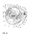
FIGS. 2 and10 , theretention latch assembly 74 selectively raises and lowers thehousing 40. Any number of known retention latches are suitable, including those disclosed inU.S. Pat. No. 7,191,490 to Lee et al .,U.S. Pat. No. 6,732,406 to Oh ,U.S. Pat. No. 6,735,816 to Oh et al ., andU.S. Pat. No. 6,991,667 to Yang et al ., incorporated herein by reference in their entirety. Another suitable description is found inU.S. Pat. No. 8,032,983 to Griffith et al ., which is incorporated herein by reference in its entirety. - Referring to
FIGS 1 and2 , thehousing 40 is removably retained on thehandle assembly 12 by thelatch assembly 74. When installed on thehandle 12, thehousing outlet grill 68 fluidly communicates with themotor inlet 16b within thehandle assembly 12, through alignedhousing outlet grill 68 and further through abore 60c of anannular seal member 61 mounted on ahousing base 100 on thehandle 12. - As best shown in
FIGS. 2 and10 , thehousing outlet grill 68 rests on anupper sealing face 60a of theseal member 61. Alower end 60e ofseal member 61 is in fluid communication with themotor inlet 16b. Theseal member 61 is trapped for up-and-down movement on acollar structure motor inlet 16b. A generally U-shapedslide lock member 71 is mounted to slide generally horizontally in and out on thehousing base 100 in a substantially straight path, in sliding contact with portions of the trappedseal member 61 to cam the seal member up and down. - To configure the dirt
separation module assembly 26 for use as a bagged system, theslide lock member 71 is pulled out away from the handle 12 (forward) allowing thehousing 40 to drop down below thecover sealing surface 46. The user grasps thehousing 40 by thegrip 70 and pulls thehousing 40 out of thehandle 12. The user then inserts thefilter bag assembly 38 inside of thehousing 40 so that theinlet interface structure 58 rests on a lip (not shown) adjacent thehousing 40 sealingsurface 66. With thehousing 40 still removed, theinlet guide 36 is inserted into thecover 34 from below, and the lockingtabs 54 are inserted into the lockingreceiver 44 and rotated ¼ turn to removably retain theinlet guide 36 on thecover 34. Thehousing 40 with thefilter bag assembly 38 is then inserted into thehandle 12 under thecover 34 and on thelatch assembly 74. The user pushes in the slide lock member 71 (rearward), raising thehousing 40 until theupper sealing surface 66 sealingly mates with the lowercover sealing surface 46. Simultaneously, thegasket 64 on thelower mating surface 56 of the inlet guide 36 seals the filter bag workingair inlet 62 to provide working air flow through the dirtseparation module assembly 26 as illustrated inFIG. 8 . In use, as dirty working air is drawn through the vacuum cleaner, theclear cover 34 allows the user to see dirty air entering thefilter bag assembly 38 around thehelix inlet guide 38. - Alternatively, the user can employ the
optional standpipe 200 andgrill 210 to convert thevacuum cleaner 10 to a conventional bagless unit. In operation, a user pulls theslide lock member 71 out away from the handle 12 (forward) allowing thehousing 40 to drop down below thecover sealing surface 46. The user grasps thehousing 40 by thegrip 70 and pulls thehousing 40 out of thehandle 12. Thefilter bag assembly 38 is removed from thehousing 40. The user inserts thestandpipe 200 over thehousing 40outlet 60. The user then reaches up inside thecover 34, grasps thehelical inlet guide 36, rotates the inlet guide 36¼ turn, and removes the helical inlet guide 36 from the top of thecover 34. The user then inserts theexhaust grill 210 in thecover 34 in reverse order. Thehousing 40 with thestandpipe 200 is inserted into thehandle 12 under thecover 34 and on thelatch assembly 74. The user pushes in the slide lock member 71 (rearward), raising thehousing 40 until theupper sealing surface 66 sealingly mates with the lowercover sealing surface 46. Simultaneously, theupper end 204 of thestandpipe 200 sealingly engages thegasket 208 on the baglesscyclone exhaust grill 206 to provide working air flow through the dirtseparation module assembly 26 as illustrated inFIG. 10 . - It is intended that the following claims define the scope of the invention and that the method and apparatus within the scope of these claims and their equivalents be covered thereby. This description of the invention should be understood to include all novel and non-obvious combinations of elements described herein, and claims may be presented in this or a later application to any novel and non-obvious combination of these elements. Moreover, the foregoing embodiments are illustrative, and no single feature or element is essential to all possible combinations that may be claimed in this or a later application. For example, other inventions arising from this disclosure may include any combination of the following concepts set forth in outline form:
- A1. A vacuum cleaner system, comprising:
- a vacuum cleaner comprising a dirt separating and collecting system having a housing defining a chamber with a tangential air inlet and an air outlet, and configured to receive a filter module removably mounted within the chamber to separate dirt from a working air stream passing from the air inlet to the air outlet;
- a bagged filter module comprising a filter bag; and
- a bagless filter module;
- wherein the bagged filter module and the bagless filter module are alternatively mounted within the chamber and fluidly coupled with the air inlet and the air outlet.
- A2. The vacuum cleaner system of claim A1, wherein the housing comprises a stationary portion and a removable portion which collectively define the chamber, wherein the removable portion is selectively removable from the vacuum cleaner without removing the stationary portion.
- A3. The vacuum cleaner system of claim A2, wherein the air inlet is formed in the stationary portion and the air outlet is formed in the removable portion.
- A4. The vacuum cleaner system of claim A2, and further comprising a latch assembly that selectively lowers the removable portion away from the stationary portion to permit access to the filter module in the chamber.
- A5. The vacuum cleaner system of claim A1, wherein the housing comprises a cover and a cup selectively removable from the cover, wherein the air inlet is formed in the cover.
- A6. The vacuum cleaner system of claim A5, wherein the air outlet is formed in the cup.
- A7. The vacuum cleaner system of claim A1, and further comprising an attachment mechanism for removably attaching the filter module to the housing.
- A8. The vacuum cleaner system of claim A7, wherein the attachment mechanism comprises a bayonet mount.
- A9. The vacuum cleaner system of claim A8, wherein the bayonet mount comprises a male portion provided on one of the housing and the filter module, and a female portion provided on the other of the housing and the filter module.
- A10. The vacuum cleaner system of claim A1, and further comprising a pre-motor filter provided in the housing and fluidly connected between the filter module and the air outlet.
- A11. The vacuum cleaner system of claim A1, wherein the bagged filter module further comprises a helical inlet guide disposed within the housing and directing the working air stream from the air inlet to the filter bag along a helical pathway.
- A12. The vacuum cleaner system of claim A1, wherein the bagless filter module comprises a cyclonic filter module.
- A13. The vacuum cleaner system of claim A12, wherein the cyclonic filter module comprises an exhaust grill.
- A14. The vacuum cleaner system of claim A13, wherein the cyclonic filter module further comprises a stand pipe coupled between the exhaust grill and the air outlet.
- B1. A vacuum cleaner comprising:
- a body having a suction nozzle;
- a dirt separating and collecting system provided on the body and comprising:
- a housing defining a chamber with an air inlet and an air outlet;
- a filter bag removably mounted within the chamber to separate and collect dirt from a working air stream passing from the air inlet to the air outlet; and
- a helical inlet guide disposed within the housing and directing the working air stream from the air inlet to the filter bag along a helical pathway; and
- a suction source fluidly connected to the suction nozzle and to the air inlet for establishing and maintaining a dirt-containing working airstream from the suction nozzle to the chamber;
- wherein at least a portion of the housing is removable from the body to permit the filter bag to be removed from the chamber.
- B2. The vacuum cleaner of claim B1, wherein the helical inlet guide comprises a helical ramp and a lip provided on the outer edge of the helical ramp.
- B3. The vacuum cleaner of claim B1, and further comprising a pre-motor filter provided in the housing and fluidly connected between the filter bag and the air outlet.
- B4. The vacuum cleaner of claim B1, wherein the housing comprises a stationary portion within contains the helical inlet guide and a removable portion which contains the filter bag, and wherein the removable portion is selectively removable from the vacuum cleaner without removing the stationary portion such that the filter bag can be selectively removed from the chamber.
- B5. The vacuum cleaner of claim B4, wherein the air inlet is formed in the stationary portion and the air outlet is formed in the removable portion.
Claims (6)
- A vacuum cleaner comprising:a body having a suction nozzle;a dirt separating and collecting system provided on the body comprising:a housing defining a chamber with an air inlet and an air outlet;a filter bag removably mounted within the chamber to separate and collect dirt from a working air stream passing from the air inlet to the air outlet; anda helical inlet guide disposed within the housing and directing the working air stream from the air inlet to the filter bag along a helical pathway; anda suction source fluidly connected to the suction nozzle and to the air inlet for establishing and maintaining a dirt-containing working airstream from the suction nozzle to the chamber;wherein the housing is at least partially transparent to permit the helical inlet guide to be viewed from the exterior of the vacuum cleaner.
- The vacuum cleaner of claim 1, wherein the helical inlet guide comprises a helical ramp and a lip provided on the outer edge of the helical ramp.
- The vacuum cleaner of claim 1, and further comprising a pre-motor filter provided in the housing and fluidly connected between the filter bag and the air outlet.
- The vacuum cleaner of claim 1, wherein the housing comprises a stationary portion within contains the helical inlet guide and a removable portion which contains the filter bag, and wherein the removable portion is selectively removable from the vacuum cleaner without removing the stationary portion such that the filter bag can be selectively removed from the chamber.
- The vacuum cleaner of claim 4, wherein the stationary portion is at least partially transparent and the removable portion is opaque.
- The vacuum cleaner of claim 4, wherein the air inlet is formed in the stationary portion and the air outlet is formed in the removable portion.
Priority Applications (1)
| Application Number | Priority Date | Filing Date | Title |
|---|---|---|---|
| EP16173661.6A EP3095366B1 (en) | 2012-03-08 | 2013-03-04 | Vacuum cleaner system |
Applications Claiming Priority (1)
| Application Number | Priority Date | Filing Date | Title |
|---|---|---|---|
| US201261608288P | 2012-03-08 | 2012-03-08 |
Related Child Applications (2)
| Application Number | Title | Priority Date | Filing Date |
|---|---|---|---|
| EP16173661.6A Division-Into EP3095366B1 (en) | 2012-03-08 | 2013-03-04 | Vacuum cleaner system |
| EP16173661.6A Division EP3095366B1 (en) | 2012-03-08 | 2013-03-04 | Vacuum cleaner system |
Publications (3)
| Publication Number | Publication Date |
|---|---|
| EP2636348A2 true EP2636348A2 (en) | 2013-09-11 |
| EP2636348A3 EP2636348A3 (en) | 2015-08-05 |
| EP2636348B1 EP2636348B1 (en) | 2016-07-13 |
Family
ID=47779955
Family Applications (2)
| Application Number | Title | Priority Date | Filing Date |
|---|---|---|---|
| EP13157526.8A Active EP2636348B1 (en) | 2012-03-08 | 2013-03-04 | Vacuum cleaner and vacuum cleaner system |
| EP16173661.6A Active EP3095366B1 (en) | 2012-03-08 | 2013-03-04 | Vacuum cleaner system |
Family Applications After (1)
| Application Number | Title | Priority Date | Filing Date |
|---|---|---|---|
| EP16173661.6A Active EP3095366B1 (en) | 2012-03-08 | 2013-03-04 | Vacuum cleaner system |
Country Status (4)
| Country | Link |
|---|---|
| US (3) | US9149165B2 (en) |
| EP (2) | EP2636348B1 (en) |
| CN (1) | CN103300791B (en) |
| AU (1) | AU2013200904B2 (en) |
Cited By (4)
| Publication number | Priority date | Publication date | Assignee | Title |
|---|---|---|---|---|
| EP2452604A3 (en) * | 2010-11-16 | 2013-10-30 | Samsung Electronics Co., Ltd. | Cyclone dust collecting apparatus and vacuum cleaner having the same |
| WO2018054501A1 (en) * | 2016-09-26 | 2018-03-29 | Aktiebolaget Electrolux | Vacuum cleaner with improved air flow |
| WO2018141412A1 (en) * | 2017-02-06 | 2018-08-09 | Aktiebolaget Electrolux | Separation system for vacuum cleaner and vacuum cleaner comprising the separation system |
| WO2019169225A1 (en) * | 2018-03-02 | 2019-09-06 | Tti (Macao Commercial Offshore) Limited | Vacuum cleaner |
Families Citing this family (28)
| Publication number | Priority date | Publication date | Assignee | Title |
|---|---|---|---|---|
| EP2117400A4 (en) * | 2006-12-12 | 2010-06-23 | Gbd Corp | Convertible surface cleaning apparatus |
| US9149165B2 (en) * | 2012-03-08 | 2015-10-06 | Bissell Homecare, Inc. | Vacuum cleaner and vacuum cleaner system |
| US9642508B1 (en) * | 2012-04-16 | 2017-05-09 | Billy Goat Indutries, Inc. | Debris-collecting apparatus and method of collecting debris |
| AU2014352815B2 (en) * | 2013-11-22 | 2017-09-07 | Techtronic Industries Co. Ltd. | Vacuum cleaner including a removable dirt collection assembly |
| USD775440S1 (en) * | 2014-01-03 | 2016-12-27 | Samsung Electronics Co., Ltd. | Cleaner |
| USD775442S1 (en) * | 2014-01-03 | 2016-12-27 | Samsung Electronics Co., Ltd. | Cleaner |
| USD775444S1 (en) * | 2014-01-03 | 2016-12-27 | Samsung Electronics Co., Ltd. | Cleaner |
| JP1530912S (en) * | 2014-09-16 | 2015-08-10 | ||
| USD759919S1 (en) * | 2014-12-30 | 2016-06-21 | Bissell Homecare, Inc. | Vacuum cleaner upright portion |
| USD768944S1 (en) * | 2015-10-29 | 2016-10-11 | Jiangsu Midea Cleaning Appliances Co., Ltd. | Dust collector |
| CN105857369B (en) * | 2016-04-06 | 2018-05-08 | 赵建康 | A kind of multipurpose separated type pulse dust trolley |
| CA171682S (en) * | 2016-11-08 | 2018-06-12 | Jiangsu Midea Cleaning Appliances Co Ltd | Vertical vacuum cleaner |
| US10750915B2 (en) | 2017-01-09 | 2020-08-25 | Emerson Electric Co. | Vacuum cleaning systems and methods including slide out drum and filter interlock device |
| GB201706357D0 (en) * | 2017-04-21 | 2017-06-07 | Grey Tech Ltd | Bagged vacuum cleaner |
| US10099659B1 (en) * | 2017-04-24 | 2018-10-16 | Emerson Electric Co. | Vehicle vacuum module and methods of installing same |
| CN109770789B (en) * | 2019-02-28 | 2024-03-29 | 小狗电器互联网科技(北京)股份有限公司 | Dust collecting cup assembly structure |
| EP4000487A4 (en) * | 2019-07-18 | 2023-01-18 | Koki Holdings Co., Ltd. | Vacuum cleaner |
| USD986521S1 (en) * | 2020-08-06 | 2023-05-16 | Jiangsu Midea Cleaning Appliances Co., Ltd. | Vacuum cleaner |
| USD993556S1 (en) * | 2021-01-14 | 2023-07-25 | Ka Shui Manufactory Co., Ltd. | Vacuum cleaner |
| USD995966S1 (en) * | 2021-01-14 | 2023-08-15 | Ka Shui Manufactory Co., Ltd. | Vacuum cleaner |
| KR20220115253A (en) * | 2021-02-10 | 2022-08-17 | 삼성전자주식회사 | Cleaning device having vacuum cleaner and docking station |
| USD996756S1 (en) * | 2021-04-26 | 2023-08-22 | Bissell Inc. | Cleaning foot for a floor cleaner |
| USD996757S1 (en) * | 2021-05-04 | 2023-08-22 | Bissell Inc. | Cleaning foot for a floor cleaner |
| USD1005628S1 (en) * | 2021-05-07 | 2023-11-21 | Bissell Inc. | Cleaning foot for a vacuum cleaner |
| USD1004870S1 (en) * | 2021-06-11 | 2023-11-14 | Bissell Inc. | Cleaning foot for a vacuum cleaner |
| USD984769S1 (en) * | 2021-06-22 | 2023-04-25 | Bissell Inc. | Body for a floor cleaner |
| USD984768S1 (en) * | 2021-06-22 | 2023-04-25 | Bissell Inc. | Body for a floor cleaner |
| USD1017156S1 (en) | 2022-05-09 | 2024-03-05 | Dupray Ventures Inc. | Cleaner |
Citations (6)
| Publication number | Priority date | Publication date | Assignee | Title |
|---|---|---|---|---|
| US6732406B2 (en) | 2001-01-11 | 2004-05-11 | Samsung Kwangju Electronics Co., Ltd. | Upright type vacuum cleaner |
| US6735816B2 (en) | 2001-06-04 | 2004-05-18 | Samsung Gwangju Electronics Co., Ltd. | Upright-type vacuum cleaner |
| US6991667B2 (en) | 2003-10-07 | 2006-01-31 | Samsung Gwangju Electronics Co., Ltd. | Attaching and detaching device for contaminant collecting receptacle of cyclone separator |
| US7191490B2 (en) | 2003-05-21 | 2007-03-20 | Samsung Gwangju Electronics Co., Ltd. | Soil collection receptacle attaching/detaching apparatus for cyclone vacuum cleaner and vacuum cleaner having the same |
| US7708789B2 (en) | 2003-10-22 | 2010-05-04 | Bissell Homecare, Inc. | Vacuum cleaner with cyclonic dirt separation and bottom discharge dirt cup with filter |
| US8032983B2 (en) | 2007-05-17 | 2011-10-11 | Bissell Homecare, Inc. | Dust cup latch for cyclone separator vacuum |
Family Cites Families (99)
| Publication number | Priority date | Publication date | Assignee | Title |
|---|---|---|---|---|
| US1145047A (en) | 1909-05-03 | 1915-07-06 | Santo Mfg Company | Vacuum cleaning apparatus. |
| GB205155A (en) | 1922-07-04 | 1923-10-04 | Robert Powell Sweeny | Air induction cleaning apparatus |
| US2210953A (en) | 1936-08-05 | 1940-08-13 | Ohio Citizens Trust Company | Suction cleaner |
| BE425021A (en) | 1936-12-05 | |||
| US2539195A (en) | 1950-05-02 | 1951-01-23 | Gen Electric | Inlet dirt deflector and filter arrangement for suction cleaners |
| US2684232A (en) | 1951-06-27 | 1954-07-20 | William J Caldwell | Centrifugal air washer and conditioner |
| FR1215496A (en) | 1958-02-14 | 1960-04-19 | Fortuna Werke Spezialmaschinen | Dust filter |
| US3180071A (en) | 1960-10-26 | 1965-04-27 | Louis C Nolte | Suction cleaner |
| GB934293A (en) | 1961-06-23 | 1963-08-14 | Atomic Energy Authority Uk | Improvements in or relating to vacuum cleaners |
| US3320727A (en) | 1965-08-02 | 1967-05-23 | Mitchell Co John E | Portable vacuum cleaning machine |
| US3636681A (en) * | 1970-03-20 | 1972-01-25 | Singer Co | Vacuum cleaner filter assembly |
| DE2038045C3 (en) | 1970-07-31 | 1981-12-10 | Siemens AG, 1000 Berlin und 8000 München | cyclone |
| GB1418010A (en) | 1972-12-08 | 1975-12-17 | Thorne Son Ltd J B | Gas filtration apparatus |
| NL177187C (en) | 1974-01-16 | 1985-08-16 | Nederlandse Gasunie Nv | DEVICE FOR SEPARATING POLLUTANTS FROM GASES. |
| DE2738850A1 (en) | 1977-08-29 | 1979-03-15 | Hilti Ag | Suction cleaner with kettle shaped container - is fitted with filter bag projecting into container and with flow in opening and adjoining guide metal |
| US4216563A (en) | 1979-04-06 | 1980-08-12 | Chemko Industries, Inc. | Combined dry and wet carpet cleaner |
| US4287635A (en) | 1979-05-07 | 1981-09-08 | Jacobs Paul G | Wet and dry vacuum cleaner |
| US4262384A (en) | 1980-01-25 | 1981-04-21 | The Scott & Fetzer Company | Vacuum cleaner bag assembly |
| US4314385A (en) | 1980-06-26 | 1982-02-09 | Wln Products | Carpet cleaning system |
| SE434469B (en) | 1982-12-13 | 1984-07-30 | Soederhamn Ind Arbetshygien Ab | STOFTAVSKILJARAGGREGAT |
| SE460757B (en) | 1988-01-19 | 1989-11-20 | Electrolux Ab | DEVICE FOR SEPARATION OF HEAVY GOODS IN A DUST CLEANER |
| US5145499A (en) | 1990-09-21 | 1992-09-08 | Notetry Limited | Disposable bin for cyclonic vacuum |
| US5090976A (en) | 1990-09-21 | 1992-02-25 | Notetry Limited | Dual cyclonic vacuum cleaner with disposable liner |
| US5400465A (en) * | 1994-03-30 | 1995-03-28 | Home Care Industries, Inc. | Vacuum cleaner with charge generator and bag therefor |
| AU5921496A (en) | 1995-10-04 | 1997-04-28 | Pro-Team, Inc. | Cyclonic vacuum cleaner |
| SE506079C2 (en) | 1995-12-28 | 1997-11-10 | Electrolux Ab | Additive device for a vacuum cleaner |
| GB9603745D0 (en) | 1996-02-22 | 1996-04-24 | Vax Ltd | Apparatus for cleaning floors, carpets and the like |
| SE508133C2 (en) | 1996-12-18 | 1998-08-31 | Electrolux Ab | Additive device for a vacuum cleaner |
| SE508515C2 (en) | 1997-02-13 | 1998-10-12 | Electrolux Ab | Device for a cyclone vacuum cleaner |
| SE508525C2 (en) | 1997-02-13 | 1998-10-12 | Electrolux Ab | Cyclone separator for a vacuum cleaner |
| SE508524C2 (en) | 1997-02-13 | 1998-10-12 | Electrolux Ab | Device for a cyclone vacuum cleaner |
| ES2171875T3 (en) | 1997-06-20 | 2002-09-16 | Candy Spa | DOMESTIC VACUUM CLEANER WITH AXIAL CYCLONE. |
| US6003196A (en) * | 1998-01-09 | 1999-12-21 | Royal Appliance Mfg. Co. | Upright vacuum cleaner with cyclonic airflow |
| US6070291A (en) * | 1998-01-09 | 2000-06-06 | Royal Appliance Mfg. Co. | Upright vacuum cleaner with cyclonic air flow |
| US6195835B1 (en) * | 1998-12-02 | 2001-03-06 | Samsung Kwangju Electronics Co., Ltd. | Vacuum cleaner having a cyclone dust collecting device |
| KR20010001213A (en) | 1999-06-02 | 2001-01-05 | 구자홍 | cyclone dust collector |
| US6178590B1 (en) | 2000-03-20 | 2001-01-30 | Lindsay Manufacturing, Inc. | Vacuum cleaner cannister with removable bag |
| US6553610B1 (en) | 2000-06-27 | 2003-04-29 | Proteam, Inc. | Modular vacuum cleaning system |
| US6428589B1 (en) | 2000-09-29 | 2002-08-06 | Royal Appliance Mfg. Co. | Two-stage particle separator for vacuum cleaners |
| US6485536B1 (en) | 2000-11-08 | 2002-11-26 | Proteam, Inc. | Vortex particle separator |
| SE517750C2 (en) | 2000-11-17 | 2002-07-09 | Electrolux Ab | Vacuum cleaner |
| US6868578B1 (en) | 2001-01-11 | 2005-03-22 | Bissell Homecare, Inc. | Upright vacuum cleaner with cyclonic separation |
| SE518257C2 (en) | 2001-01-11 | 2002-09-17 | Electrolux Ab | Device for a vacuum cleaner |
| US7143469B2 (en) * | 2001-02-06 | 2006-12-05 | The Hoover Company | Dirt collecting system |
| JP2003024826A (en) | 2001-07-12 | 2003-01-28 | Casle Kk | Cyclone separator with recovery bag |
| KR100444327B1 (en) | 2002-01-30 | 2004-08-16 | 삼성광주전자 주식회사 | Filter supporting structure of an upright-type vacuum cleaner |
| KR100433408B1 (en) * | 2002-03-05 | 2004-05-31 | 삼성광주전자 주식회사 | Vacuum cleaner |
| SE521544C2 (en) * | 2002-03-08 | 2003-11-11 | Electrolux Ab | Apparatus and method for simultaneously separating and closing a tubular web in a vacuum cleaner |
| SE521474C2 (en) | 2002-03-08 | 2003-11-04 | Electrolux Ab | Device at a vacuum cleaner and cartridge for use with the device |
| US6829804B2 (en) * | 2002-03-26 | 2004-12-14 | White Consolidated, Ltd. | Filtration arrangement of a vacuum cleaner |
| KR100437116B1 (en) | 2002-05-22 | 2004-06-23 | 삼성광주전자 주식회사 | Vacuum cleaner |
| KR100437107B1 (en) | 2002-05-31 | 2004-06-23 | 삼성광주전자 주식회사 | Vacuum cleaner |
| GB0217105D0 (en) | 2002-07-24 | 2002-09-04 | Hoover Ltd | Vacuum cleaner |
| AU2003260711A1 (en) * | 2002-07-24 | 2004-02-09 | Hoover Limited | Vacuum cleaner |
| GB2394649B (en) * | 2002-11-01 | 2006-03-08 | Black & Decker Inc | Dust collection modules for vacuum cleaners |
| DE20300991U1 (en) | 2003-01-23 | 2003-04-10 | Zsa Vertriebs Gmbh Zentrale St | vacuum cleaner |
| USD495347S1 (en) | 2003-01-24 | 2004-08-31 | Wmh Tool Group, Inc. | Particle collector lid |
| CA2461238C (en) | 2003-03-17 | 2009-06-09 | Matsushita Electric Corporation Of America | Selective bag or bagless cleaning system |
| US7343643B2 (en) | 2003-03-17 | 2008-03-18 | Panasonic Corporation Of North America | Selective bag or bagless cleaning system |
| KR100471142B1 (en) * | 2003-05-21 | 2005-03-10 | 삼성광주전자 주식회사 | Cyclone dust collecting device and vacuum cleaner having the same |
| KR100474079B1 (en) | 2003-06-26 | 2005-03-14 | 삼성광주전자 주식회사 | Upright type vacuum cleaner |
| US7544224B2 (en) * | 2003-08-05 | 2009-06-09 | Electrolux Home Care Products, Inc. | Cyclonic vacuum cleaner |
| US7162770B2 (en) * | 2003-11-26 | 2007-01-16 | Electrolux Home Care Products Ltd. | Dust separation system |
| JP4236621B2 (en) | 2004-08-31 | 2009-03-11 | 三洋電機株式会社 | Electric vacuum cleaner |
| SE529547C2 (en) | 2004-12-08 | 2007-09-11 | Pullman Ermator Ab | Device for collecting dust particles or residual material |
| DE102004063214A1 (en) | 2004-12-24 | 2006-07-06 | PROAIR GmbH Gerätebau | Cleaning apparatus e.g. vacuum cleaner for e.g. household purposes, has drive unit designed as part of base unit including interface for different mounting modules, where modules are selectively connected to unit based on cleaning function |
| KR100594584B1 (en) * | 2005-04-22 | 2006-06-30 | 삼성광주전자 주식회사 | Filter assembly and cyclone dust collecting apparatus having the same |
| JP2006325883A (en) | 2005-05-25 | 2006-12-07 | Twinbird Corp | Vacuum cleaner |
| US7615109B2 (en) * | 2005-06-10 | 2009-11-10 | Electrolux Home Care Products, Inc. | Sodium bicarbonate vacuum bag inserts |
| US7645311B2 (en) * | 2005-07-12 | 2010-01-12 | Samsung Gwangju Electronics Co., Ltd. | Cyclone unit and contaminants-collecting apparatus having the same |
| US8176597B2 (en) * | 2005-07-12 | 2012-05-15 | Bissell Homecare, Inc. | Vacuum cleaner with cyclonic dirt separation |
| US7811349B2 (en) * | 2005-07-12 | 2010-10-12 | Bissell Homecare, Inc. | Vacuum cleaner with vortex stabilizer |
| US7404231B2 (en) | 2005-08-18 | 2008-07-29 | Daewoo Electronics Corporation | Dust container of upright type vacuum cleaner and supporting structure for cover thereof |
| DE102005041133B3 (en) * | 2005-08-30 | 2007-01-18 | Miele & Cie. Kg | Operation of vacuum cleaner with speed control, bag change display and dust bag recognition, reduces suction power when no bag identification is recognized |
| US7662200B2 (en) * | 2005-10-18 | 2010-02-16 | Electrolux Home Care Products, Inc. | Vacuum bag mounting and viewing features |
| CN100500073C (en) * | 2005-12-05 | 2009-06-17 | 苏州金莱克家用电器有限公司 | Dust remover of vacuum cleaner |
| US20070163075A1 (en) * | 2006-01-17 | 2007-07-19 | Butler Dennis C | Stair cleaning vacuum cleaner |
| US20070209334A1 (en) | 2006-03-10 | 2007-09-13 | Gbd Corp. | Vacuum cleaner with a removable screen |
| KR101250077B1 (en) | 2006-04-04 | 2013-04-02 | 엘지전자 주식회사 | Dust collecting unit of vacuum cleaner |
| US7581287B2 (en) | 2006-06-14 | 2009-09-01 | Panasonic Corporation Of North America | Vacuum cleaner with spiral air guide |
| US8713751B2 (en) | 2006-12-12 | 2014-05-06 | G.B.D. Corp. | Surface cleaning apparatus with liner bag |
| US7744683B2 (en) | 2007-04-23 | 2010-06-29 | Yuejie Zhang | Transparent filterable dust bag with support container for vacuum cleaner |
| US20080264015A1 (en) * | 2007-04-30 | 2008-10-30 | Samsung Gwangju Electronics Co., Ltd | Dust compressing apparatus of vacuum cleaner |
| US7717973B2 (en) | 2007-09-05 | 2010-05-18 | Samsung Gwangju Elecetronics Co., Ltd. | Cyclone dust-separating apparatus of vacuum cleaner |
| NL2001293C2 (en) | 2008-02-18 | 2009-08-19 | Jadyba B V | Gas cleaner for at least partially separating entrained components from a contaminated gas stream. |
| KR101471026B1 (en) | 2008-03-05 | 2014-12-11 | 삼성전자주식회사 | Vacuum cleaner in which dust bag or cyclone dust collecting apparatus is selectively mounted |
| US7931740B2 (en) | 2008-06-20 | 2011-04-26 | The Boeing Company | Cyclone separator |
| US8062398B2 (en) | 2008-12-19 | 2011-11-22 | Bissell Homecare, Inc. | Vacuum cleaner and cyclone module therefor |
| US8424153B2 (en) * | 2009-03-19 | 2013-04-23 | Bissell Homecare, Inc. | Vacuum cleaner and filters therefor |
| AU2010201003B2 (en) * | 2009-03-20 | 2014-05-08 | Bissell Homecare, Inc. | Filter locking arrangement for a vacuum cleaner |
| US7955404B2 (en) | 2009-10-29 | 2011-06-07 | Tony Lin | Dust collector |
| JP2011152240A (en) * | 2010-01-26 | 2011-08-11 | Twinbird Corp | Vacuum cleaner |
| US8640304B2 (en) * | 2010-03-12 | 2014-02-04 | G.B.D. Corp. | Cyclone construction for a surface cleaning apparatus |
| CN201743622U (en) | 2010-05-14 | 2011-02-16 | 莱克电气股份有限公司 | Cyclone dust removal device of dust collector |
| JP5101720B1 (en) * | 2011-07-21 | 2012-12-19 | シャープ株式会社 | Cyclone separation device and vacuum cleaner provided with the same |
| CN102949148B (en) * | 2011-08-25 | 2014-10-01 | 莱克电气股份有限公司 | Steam dust-absorbing and cleaning dual-purpose machine with parallel structure |
| US9149165B2 (en) * | 2012-03-08 | 2015-10-06 | Bissell Homecare, Inc. | Vacuum cleaner and vacuum cleaner system |
| US8997310B2 (en) * | 2012-10-12 | 2015-04-07 | Electrolux Home Care Products, Inc. | Vacuum cleaner cyclone with helical cyclone expansion region |
| US9113764B2 (en) * | 2013-08-12 | 2015-08-25 | Emerson Electric Co. | Vacuum filter bag mounting apparatus and methods of operation |
-
2012
- 2012-07-10 US US13/545,500 patent/US9149165B2/en active Active
-
2013
- 2013-02-19 AU AU2013200904A patent/AU2013200904B2/en active Active
- 2013-03-04 EP EP13157526.8A patent/EP2636348B1/en active Active
- 2013-03-04 EP EP16173661.6A patent/EP3095366B1/en active Active
- 2013-03-07 CN CN201310073359.7A patent/CN103300791B/en active Active
-
2015
- 2015-10-05 US US14/874,680 patent/US9717380B2/en active Active
-
2017
- 2017-06-23 US US15/631,010 patent/US10398268B2/en active Active
Patent Citations (6)
| Publication number | Priority date | Publication date | Assignee | Title |
|---|---|---|---|---|
| US6732406B2 (en) | 2001-01-11 | 2004-05-11 | Samsung Kwangju Electronics Co., Ltd. | Upright type vacuum cleaner |
| US6735816B2 (en) | 2001-06-04 | 2004-05-18 | Samsung Gwangju Electronics Co., Ltd. | Upright-type vacuum cleaner |
| US7191490B2 (en) | 2003-05-21 | 2007-03-20 | Samsung Gwangju Electronics Co., Ltd. | Soil collection receptacle attaching/detaching apparatus for cyclone vacuum cleaner and vacuum cleaner having the same |
| US6991667B2 (en) | 2003-10-07 | 2006-01-31 | Samsung Gwangju Electronics Co., Ltd. | Attaching and detaching device for contaminant collecting receptacle of cyclone separator |
| US7708789B2 (en) | 2003-10-22 | 2010-05-04 | Bissell Homecare, Inc. | Vacuum cleaner with cyclonic dirt separation and bottom discharge dirt cup with filter |
| US8032983B2 (en) | 2007-05-17 | 2011-10-11 | Bissell Homecare, Inc. | Dust cup latch for cyclone separator vacuum |
Cited By (8)
| Publication number | Priority date | Publication date | Assignee | Title |
|---|---|---|---|---|
| EP2452604A3 (en) * | 2010-11-16 | 2013-10-30 | Samsung Electronics Co., Ltd. | Cyclone dust collecting apparatus and vacuum cleaner having the same |
| US8914941B2 (en) | 2010-11-16 | 2014-12-23 | Samsung Electronics Co., Ltd. | Cyclone dust collecting apparatus and vacuum cleaner having the same |
| WO2018054501A1 (en) * | 2016-09-26 | 2018-03-29 | Aktiebolaget Electrolux | Vacuum cleaner with improved air flow |
| CN109715020A (en) * | 2016-09-26 | 2019-05-03 | 伊莱克斯公司 | The improved vacuum cleaner of air stream |
| WO2018141412A1 (en) * | 2017-02-06 | 2018-08-09 | Aktiebolaget Electrolux | Separation system for vacuum cleaner and vacuum cleaner comprising the separation system |
| CN110167411A (en) * | 2017-02-06 | 2019-08-23 | 伊莱克斯公司 | Separation system for vacuum cleaner and the vacuum cleaner including separation system |
| US11529035B2 (en) | 2017-02-06 | 2022-12-20 | Aktiebolaget Electrolux | Separation system for vacuum cleaner and vacuum cleaner comprising the separation system |
| WO2019169225A1 (en) * | 2018-03-02 | 2019-09-06 | Tti (Macao Commercial Offshore) Limited | Vacuum cleaner |
Also Published As
| Publication number | Publication date |
|---|---|
| EP2636348B1 (en) | 2016-07-13 |
| US20160022103A1 (en) | 2016-01-28 |
| EP3095366A3 (en) | 2017-03-08 |
| EP3095366B1 (en) | 2021-10-06 |
| EP2636348A3 (en) | 2015-08-05 |
| US10398268B2 (en) | 2019-09-03 |
| US20130232724A1 (en) | 2013-09-12 |
| EP3095366A2 (en) | 2016-11-23 |
| CN103300791A (en) | 2013-09-18 |
| US20170280953A1 (en) | 2017-10-05 |
| CN103300791B (en) | 2017-05-24 |
| AU2013200904B2 (en) | 2014-06-12 |
| AU2013200904A1 (en) | 2013-09-26 |
| US9717380B2 (en) | 2017-08-01 |
| US9149165B2 (en) | 2015-10-06 |
Similar Documents
| Publication | Publication Date | Title |
|---|---|---|
| US10398268B2 (en) | Vacuum cleaner | |
| US11793381B2 (en) | Cyclone module for vacuum cleaner | |
| AU2009227855B2 (en) | Vacuum cleaner and cyclone module therefor | |
| US8495788B2 (en) | Filter locking arrangement for a vacuum cleaner | |
| AU2006200983B2 (en) | Cyclone dust-collecting device and vacuum cleaner having the same | |
| US8161599B2 (en) | Cyclonic vacuum cleaner with improved filter cartridge | |
| US20050223519A1 (en) | Light weight bagless vacuum cleaner | |
| CA2466823C (en) | Dust collecting apparatus for a vacuum cleaner having two cyclone chambers | |
| CN110680238A (en) | Electric vacuum cleaner | |
| EP2524641A2 (en) | Apparatus for collecting sucked up materials for use in vacuum cleaner appliances | |
| JP6430112B2 (en) | Electric vacuum cleaner | |
| AU2014100580A4 (en) | Vacuum cleaner and vacuum cleaner system | |
| KR102049860B1 (en) | vacuum cleaner | |
| AU2015100048A4 (en) | Cyclonic vacuum cleaner with improved collection chamber |
Legal Events
| Date | Code | Title | Description |
|---|---|---|---|
| PUAI | Public reference made under article 153(3) epc to a published international application that has entered the european phase |
Free format text: ORIGINAL CODE: 0009012 |
|
| AK | Designated contracting states |
Kind code of ref document: A2 Designated state(s): AL AT BE BG CH CY CZ DE DK EE ES FI FR GB GR HR HU IE IS IT LI LT LU LV MC MK MT NL NO PL PT RO RS SE SI SK SM TR |
|
| AX | Request for extension of the european patent |
Extension state: BA ME |
|
| PUAL | Search report despatched |
Free format text: ORIGINAL CODE: 0009013 |
|
| AK | Designated contracting states |
Kind code of ref document: A3 Designated state(s): AL AT BE BG CH CY CZ DE DK EE ES FI FR GB GR HR HU IE IS IT LI LT LU LV MC MK MT NL NO PL PT RO RS SE SI SK SM TR |
|
| AX | Request for extension of the european patent |
Extension state: BA ME |
|
| RIC1 | Information provided on ipc code assigned before grant |
Ipc: A47L 9/14 20060101ALI20150629BHEP Ipc: A47L 5/28 20060101AFI20150629BHEP Ipc: A47L 9/16 20060101ALI20150629BHEP |
|
| 17P | Request for examination filed |
Effective date: 20151130 |
|
| RBV | Designated contracting states (corrected) |
Designated state(s): AL AT BE BG CH CY CZ DE DK EE ES FI FR GB GR HR HU IE IS IT LI LT LU LV MC MK MT NL NO PL PT RO RS SE SI SK SM TR |
|
| GRAP | Despatch of communication of intention to grant a patent |
Free format text: ORIGINAL CODE: EPIDOSNIGR1 |
|
| INTG | Intention to grant announced |
Effective date: 20160122 |
|
| GRAS | Grant fee paid |
Free format text: ORIGINAL CODE: EPIDOSNIGR3 |
|
| GRAA | (expected) grant |
Free format text: ORIGINAL CODE: 0009210 |
|
| RIN1 | Information on inventor provided before grant (corrected) |
Inventor name: FESTER, JOSEPH A. Inventor name: KREBS, ALAN J. |
|
| AK | Designated contracting states |
Kind code of ref document: B1 Designated state(s): AL AT BE BG CH CY CZ DE DK EE ES FI FR GB GR HR HU IE IS IT LI LT LU LV MC MK MT NL NO PL PT RO RS SE SI SK SM TR |
|
| REG | Reference to a national code |
Ref country code: GB Ref legal event code: FG4D |
|
| REG | Reference to a national code |
Ref country code: AT Ref legal event code: REF Ref document number: 811589 Country of ref document: AT Kind code of ref document: T Effective date: 20160715 Ref country code: CH Ref legal event code: EP |
|
| REG | Reference to a national code |
Ref country code: IE Ref legal event code: FG4D |
|
| REG | Reference to a national code |
Ref country code: DE Ref legal event code: R096 Ref document number: 602013009267 Country of ref document: DE |
|
| REG | Reference to a national code |
Ref country code: LT Ref legal event code: MG4D |
|
| REG | Reference to a national code |
Ref country code: NL Ref legal event code: MP Effective date: 20160713 |
|
| REG | Reference to a national code |
Ref country code: AT Ref legal event code: MK05 Ref document number: 811589 Country of ref document: AT Kind code of ref document: T Effective date: 20160713 |
|
| PG25 | Lapsed in a contracting state [announced via postgrant information from national office to epo] |
Ref country code: IS Free format text: LAPSE BECAUSE OF FAILURE TO SUBMIT A TRANSLATION OF THE DESCRIPTION OR TO PAY THE FEE WITHIN THE PRESCRIBED TIME-LIMIT Effective date: 20161113 Ref country code: LT Free format text: LAPSE BECAUSE OF FAILURE TO SUBMIT A TRANSLATION OF THE DESCRIPTION OR TO PAY THE FEE WITHIN THE PRESCRIBED TIME-LIMIT Effective date: 20160713 Ref country code: RS Free format text: LAPSE BECAUSE OF FAILURE TO SUBMIT A TRANSLATION OF THE DESCRIPTION OR TO PAY THE FEE WITHIN THE PRESCRIBED TIME-LIMIT Effective date: 20160713 Ref country code: IT Free format text: LAPSE BECAUSE OF FAILURE TO SUBMIT A TRANSLATION OF THE DESCRIPTION OR TO PAY THE FEE WITHIN THE PRESCRIBED TIME-LIMIT Effective date: 20160713 Ref country code: NL Free format text: LAPSE BECAUSE OF FAILURE TO SUBMIT A TRANSLATION OF THE DESCRIPTION OR TO PAY THE FEE WITHIN THE PRESCRIBED TIME-LIMIT Effective date: 20160713 Ref country code: FI Free format text: LAPSE BECAUSE OF FAILURE TO SUBMIT A TRANSLATION OF THE DESCRIPTION OR TO PAY THE FEE WITHIN THE PRESCRIBED TIME-LIMIT Effective date: 20160713 Ref country code: HR Free format text: LAPSE BECAUSE OF FAILURE TO SUBMIT A TRANSLATION OF THE DESCRIPTION OR TO PAY THE FEE WITHIN THE PRESCRIBED TIME-LIMIT Effective date: 20160713 Ref country code: NO Free format text: LAPSE BECAUSE OF FAILURE TO SUBMIT A TRANSLATION OF THE DESCRIPTION OR TO PAY THE FEE WITHIN THE PRESCRIBED TIME-LIMIT Effective date: 20161013 |
|
| PG25 | Lapsed in a contracting state [announced via postgrant information from national office to epo] |
Ref country code: PT Free format text: LAPSE BECAUSE OF FAILURE TO SUBMIT A TRANSLATION OF THE DESCRIPTION OR TO PAY THE FEE WITHIN THE PRESCRIBED TIME-LIMIT Effective date: 20161114 Ref country code: PL Free format text: LAPSE BECAUSE OF FAILURE TO SUBMIT A TRANSLATION OF THE DESCRIPTION OR TO PAY THE FEE WITHIN THE PRESCRIBED TIME-LIMIT Effective date: 20160713 Ref country code: BE Free format text: LAPSE BECAUSE OF FAILURE TO SUBMIT A TRANSLATION OF THE DESCRIPTION OR TO PAY THE FEE WITHIN THE PRESCRIBED TIME-LIMIT Effective date: 20160713 Ref country code: ES Free format text: LAPSE BECAUSE OF FAILURE TO SUBMIT A TRANSLATION OF THE DESCRIPTION OR TO PAY THE FEE WITHIN THE PRESCRIBED TIME-LIMIT Effective date: 20160713 Ref country code: AT Free format text: LAPSE BECAUSE OF FAILURE TO SUBMIT A TRANSLATION OF THE DESCRIPTION OR TO PAY THE FEE WITHIN THE PRESCRIBED TIME-LIMIT Effective date: 20160713 Ref country code: GR Free format text: LAPSE BECAUSE OF FAILURE TO SUBMIT A TRANSLATION OF THE DESCRIPTION OR TO PAY THE FEE WITHIN THE PRESCRIBED TIME-LIMIT Effective date: 20161014 Ref country code: LV Free format text: LAPSE BECAUSE OF FAILURE TO SUBMIT A TRANSLATION OF THE DESCRIPTION OR TO PAY THE FEE WITHIN THE PRESCRIBED TIME-LIMIT Effective date: 20160713 Ref country code: SE Free format text: LAPSE BECAUSE OF FAILURE TO SUBMIT A TRANSLATION OF THE DESCRIPTION OR TO PAY THE FEE WITHIN THE PRESCRIBED TIME-LIMIT Effective date: 20160713 |
|
| REG | Reference to a national code |
Ref country code: DE Ref legal event code: R097 Ref document number: 602013009267 Country of ref document: DE |
|
| PG25 | Lapsed in a contracting state [announced via postgrant information from national office to epo] |
Ref country code: EE Free format text: LAPSE BECAUSE OF FAILURE TO SUBMIT A TRANSLATION OF THE DESCRIPTION OR TO PAY THE FEE WITHIN THE PRESCRIBED TIME-LIMIT Effective date: 20160713 Ref country code: RO Free format text: LAPSE BECAUSE OF FAILURE TO SUBMIT A TRANSLATION OF THE DESCRIPTION OR TO PAY THE FEE WITHIN THE PRESCRIBED TIME-LIMIT Effective date: 20160713 |
|
| PLBE | No opposition filed within time limit |
Free format text: ORIGINAL CODE: 0009261 |
|
| STAA | Information on the status of an ep patent application or granted ep patent |
Free format text: STATUS: NO OPPOSITION FILED WITHIN TIME LIMIT |
|
| PG25 | Lapsed in a contracting state [announced via postgrant information from national office to epo] |
Ref country code: CZ Free format text: LAPSE BECAUSE OF FAILURE TO SUBMIT A TRANSLATION OF THE DESCRIPTION OR TO PAY THE FEE WITHIN THE PRESCRIBED TIME-LIMIT Effective date: 20160713 Ref country code: SM Free format text: LAPSE BECAUSE OF FAILURE TO SUBMIT A TRANSLATION OF THE DESCRIPTION OR TO PAY THE FEE WITHIN THE PRESCRIBED TIME-LIMIT Effective date: 20160713 Ref country code: SK Free format text: LAPSE BECAUSE OF FAILURE TO SUBMIT A TRANSLATION OF THE DESCRIPTION OR TO PAY THE FEE WITHIN THE PRESCRIBED TIME-LIMIT Effective date: 20160713 Ref country code: DK Free format text: LAPSE BECAUSE OF FAILURE TO SUBMIT A TRANSLATION OF THE DESCRIPTION OR TO PAY THE FEE WITHIN THE PRESCRIBED TIME-LIMIT Effective date: 20160713 Ref country code: BG Free format text: LAPSE BECAUSE OF FAILURE TO SUBMIT A TRANSLATION OF THE DESCRIPTION OR TO PAY THE FEE WITHIN THE PRESCRIBED TIME-LIMIT Effective date: 20161013 |
|
| 26N | No opposition filed |
Effective date: 20170418 |
|
| PG25 | Lapsed in a contracting state [announced via postgrant information from national office to epo] |
Ref country code: SI Free format text: LAPSE BECAUSE OF FAILURE TO SUBMIT A TRANSLATION OF THE DESCRIPTION OR TO PAY THE FEE WITHIN THE PRESCRIBED TIME-LIMIT Effective date: 20160713 |
|
| REG | Reference to a national code |
Ref country code: DE Ref legal event code: R119 Ref document number: 602013009267 Country of ref document: DE |
|
| REG | Reference to a national code |
Ref country code: CH Ref legal event code: PL |
|
| PG25 | Lapsed in a contracting state [announced via postgrant information from national office to epo] |
Ref country code: MC Free format text: LAPSE BECAUSE OF FAILURE TO SUBMIT A TRANSLATION OF THE DESCRIPTION OR TO PAY THE FEE WITHIN THE PRESCRIBED TIME-LIMIT Effective date: 20160713 |
|
| REG | Reference to a national code |
Ref country code: IE Ref legal event code: MM4A |
|
| REG | Reference to a national code |
Ref country code: FR Ref legal event code: ST Effective date: 20171130 |
|
| PG25 | Lapsed in a contracting state [announced via postgrant information from national office to epo] |
Ref country code: DE Free format text: LAPSE BECAUSE OF NON-PAYMENT OF DUE FEES Effective date: 20171003 Ref country code: LU Free format text: LAPSE BECAUSE OF NON-PAYMENT OF DUE FEES Effective date: 20170304 Ref country code: FR Free format text: LAPSE BECAUSE OF NON-PAYMENT OF DUE FEES Effective date: 20170331 |
|
| PG25 | Lapsed in a contracting state [announced via postgrant information from national office to epo] |
Ref country code: IE Free format text: LAPSE BECAUSE OF NON-PAYMENT OF DUE FEES Effective date: 20170304 Ref country code: CH Free format text: LAPSE BECAUSE OF NON-PAYMENT OF DUE FEES Effective date: 20170331 Ref country code: LI Free format text: LAPSE BECAUSE OF NON-PAYMENT OF DUE FEES Effective date: 20170331 |
|
| PG25 | Lapsed in a contracting state [announced via postgrant information from national office to epo] |
Ref country code: MT Free format text: LAPSE BECAUSE OF NON-PAYMENT OF DUE FEES Effective date: 20170304 |
|
| PG25 | Lapsed in a contracting state [announced via postgrant information from national office to epo] |
Ref country code: AL Free format text: LAPSE BECAUSE OF FAILURE TO SUBMIT A TRANSLATION OF THE DESCRIPTION OR TO PAY THE FEE WITHIN THE PRESCRIBED TIME-LIMIT Effective date: 20160713 |
|
| PG25 | Lapsed in a contracting state [announced via postgrant information from national office to epo] |
Ref country code: HU Free format text: LAPSE BECAUSE OF FAILURE TO SUBMIT A TRANSLATION OF THE DESCRIPTION OR TO PAY THE FEE WITHIN THE PRESCRIBED TIME-LIMIT; INVALID AB INITIO Effective date: 20130304 |
|
| PG25 | Lapsed in a contracting state [announced via postgrant information from national office to epo] |
Ref country code: CY Free format text: LAPSE BECAUSE OF NON-PAYMENT OF DUE FEES Effective date: 20160713 |
|
| PG25 | Lapsed in a contracting state [announced via postgrant information from national office to epo] |
Ref country code: MK Free format text: LAPSE BECAUSE OF FAILURE TO SUBMIT A TRANSLATION OF THE DESCRIPTION OR TO PAY THE FEE WITHIN THE PRESCRIBED TIME-LIMIT Effective date: 20160713 |
|
| PG25 | Lapsed in a contracting state [announced via postgrant information from national office to epo] |
Ref country code: TR Free format text: LAPSE BECAUSE OF FAILURE TO SUBMIT A TRANSLATION OF THE DESCRIPTION OR TO PAY THE FEE WITHIN THE PRESCRIBED TIME-LIMIT Effective date: 20160713 |
|
| REG | Reference to a national code |
Ref country code: GB Ref legal event code: 732E Free format text: REGISTERED BETWEEN 20201001 AND 20201007 |
|
| PGFP | Annual fee paid to national office [announced via postgrant information from national office to epo] |
Ref country code: GB Payment date: 20230222 Year of fee payment: 11 |
|
| P01 | Opt-out of the competence of the unified patent court (upc) registered |
Effective date: 20230528 |