EP2634640A2 - Entladevorrichtung - Google Patents
Entladevorrichtung Download PDFInfo
- Publication number
- EP2634640A2 EP2634640A2 EP13156534.3A EP13156534A EP2634640A2 EP 2634640 A2 EP2634640 A2 EP 2634640A2 EP 13156534 A EP13156534 A EP 13156534A EP 2634640 A2 EP2634640 A2 EP 2634640A2
- Authority
- EP
- European Patent Office
- Prior art keywords
- discharge
- discharge electrode
- electrode
- main
- intermediate transfer
- Prior art date
- Legal status (The legal status is an assumption and is not a legal conclusion. Google has not performed a legal analysis and makes no representation as to the accuracy of the status listed.)
- Withdrawn
Links
- 238000012546 transfer Methods 0.000 claims description 88
- 238000000034 method Methods 0.000 claims description 8
- 238000006386 neutralization reaction Methods 0.000 description 27
- 230000002265 prevention Effects 0.000 description 14
- 238000005516 engineering process Methods 0.000 description 10
- 238000004140 cleaning Methods 0.000 description 9
- 238000012986 modification Methods 0.000 description 7
- 230000004048 modification Effects 0.000 description 7
- 230000000694 effects Effects 0.000 description 6
- 238000002474 experimental method Methods 0.000 description 5
- 239000003086 colorant Substances 0.000 description 4
- 238000000926 separation method Methods 0.000 description 4
- 210000000078 claw Anatomy 0.000 description 3
- 238000007599 discharging Methods 0.000 description 3
- 230000003472 neutralizing effect Effects 0.000 description 3
- 238000001179 sorption measurement Methods 0.000 description 3
- 230000015556 catabolic process Effects 0.000 description 2
- 238000006731 degradation reaction Methods 0.000 description 2
- 230000005684 electric field Effects 0.000 description 2
- 230000005611 electricity Effects 0.000 description 2
- 238000011156 evaluation Methods 0.000 description 2
- 230000002411 adverse Effects 0.000 description 1
- 230000002950 deficient Effects 0.000 description 1
- 230000002093 peripheral effect Effects 0.000 description 1
- 238000003825 pressing Methods 0.000 description 1
- 239000011347 resin Substances 0.000 description 1
- 229920005989 resin Polymers 0.000 description 1
- 239000003381 stabilizer Substances 0.000 description 1
- 238000011144 upstream manufacturing Methods 0.000 description 1
Images




Classifications
-
- G—PHYSICS
- G03—PHOTOGRAPHY; CINEMATOGRAPHY; ANALOGOUS TECHNIQUES USING WAVES OTHER THAN OPTICAL WAVES; ELECTROGRAPHY; HOLOGRAPHY
- G03G—ELECTROGRAPHY; ELECTROPHOTOGRAPHY; MAGNETOGRAPHY
- G03G15/00—Apparatus for electrographic processes using a charge pattern
- G03G15/02—Apparatus for electrographic processes using a charge pattern for laying down a uniform charge, e.g. for sensitising; Corona discharge devices
- G03G15/0291—Apparatus for electrographic processes using a charge pattern for laying down a uniform charge, e.g. for sensitising; Corona discharge devices corona discharge devices, e.g. wires, pointed electrodes, means for cleaning the corona discharge device
-
- G—PHYSICS
- G03—PHOTOGRAPHY; CINEMATOGRAPHY; ANALOGOUS TECHNIQUES USING WAVES OTHER THAN OPTICAL WAVES; ELECTROGRAPHY; HOLOGRAPHY
- G03G—ELECTROGRAPHY; ELECTROPHOTOGRAPHY; MAGNETOGRAPHY
- G03G15/00—Apparatus for electrographic processes using a charge pattern
- G03G15/01—Apparatus for electrographic processes using a charge pattern for producing multicoloured copies
- G03G15/0142—Structure of complete machines
- G03G15/0178—Structure of complete machines using more than one reusable electrographic recording member, e.g. one for every monocolour image
- G03G15/0189—Structure of complete machines using more than one reusable electrographic recording member, e.g. one for every monocolour image primary transfer to an intermediate transfer belt
-
- H—ELECTRICITY
- H01—ELECTRIC ELEMENTS
- H01J—ELECTRIC DISCHARGE TUBES OR DISCHARGE LAMPS
- H01J37/00—Discharge tubes with provision for introducing objects or material to be exposed to the discharge, e.g. for the purpose of examination or processing thereof
- H01J37/30—Electron-beam or ion-beam tubes for localised treatment of objects
-
- G—PHYSICS
- G03—PHOTOGRAPHY; CINEMATOGRAPHY; ANALOGOUS TECHNIQUES USING WAVES OTHER THAN OPTICAL WAVES; ELECTROGRAPHY; HOLOGRAPHY
- G03G—ELECTROGRAPHY; ELECTROPHOTOGRAPHY; MAGNETOGRAPHY
- G03G2215/00—Apparatus for electrophotographic processes
- G03G2215/01—Apparatus for electrophotographic processes for producing multicoloured copies
- G03G2215/0103—Plural electrographic recording members
- G03G2215/0119—Linear arrangement adjacent plural transfer points
- G03G2215/0122—Linear arrangement adjacent plural transfer points primary transfer to an intermediate transfer belt
- G03G2215/0125—Linear arrangement adjacent plural transfer points primary transfer to an intermediate transfer belt the linear arrangement being horizontal or slanted
- G03G2215/0132—Linear arrangement adjacent plural transfer points primary transfer to an intermediate transfer belt the linear arrangement being horizontal or slanted vertical medium transport path at the secondary transfer
Definitions
- the present invention relates to a discharge device, and in particular to a technology for improving a non-uniform discharge occurring in the discharge device for generating a corona discharge, and miniaturizing the discharge device.
- Image forming apparatuses of an intermediate transfer method form a color image by overlaying toner images of, for example, colors Y (yellow), M (magenta), C (cyan) and K (black) on an intermediate transfer belt.
- the toner image carried by the intermediate transfer belt is transferred electrostatically onto a recording sheet by a second transfer roller, and then thermally fixed onto the recording sheet by a fixing device.
- the recording sheet To transport the recording sheet carrying the toner image to the fixing device, the recording sheet needs to be separated from the intermediate transfer belt. However, when the recording sheet is stuck to the intermediate transfer belt by the electrostatic adsorption force or the like, the recording sheet might not be separated.
- a separation claw for example, may be used to separate the recording sheet from the intermediate transfer belt.
- the separation claw since the separation claw contacts a surface of the recording sheet on which an image has been formed, the separation claw may scrape off unfixed toner, thereby causing an image noise to occur.
- the curvature of the second transfer roller, on which the intermediate transfer belt is suspended may be increased so that the recording sheet can be separated from the intermediate transfer belt by the rigidity (elastic restoring force) of the recording sheet itself.
- the rigidity elastic restoring force
- the electrostatic adsorption force which causes the recording sheet to be stuck to the intermediate transfer belt, is weakened by neutralizing the recording sheet by using the corona discharge (for example, see Japanese Patent Application Publication No. 09-114194 ).
- the method of neutralizing the recording sheet does not necessarily separate the recording sheet from the intermediate transfer belt with absolute certainty.
- the recording sheet is a sheet of thin paper
- separating the recording sheet becomes further difficult since a sheet of thin paper is more deformable than a sheet of regular paper. This difficulty in separating the recording sheet is considered to be attributable to non-uniform neutralization of the recording sheet which is attributable to non-uniform discharge of the corona discharge.
- the corona discharge device needs to be miniaturized.
- the miniaturization of the corona discharge device is also a demand by a charging device which charges the photosensitive drum by the corona discharge.
- a discharge device for generating a corona discharge aimed at an object facing the discharge device, the discharge device comprising: a plate-like main discharge electrode configured to receive an applied direct current voltage and generate the corona discharge aimed at the object; a plate-like auxiliary discharge electrode disposed in parallel with the main discharge electrode and configured to receive an applied direct current voltage which is opposite in polarity to the applied direct current voltage received by the main discharge electrode, thereby causing the corona discharge to occur between the main discharge electrode and the auxiliary discharge electrode; and a plate-like insulating member disposed between the main discharge electrode and the auxiliary discharge electrode, wherein the insulating member is disposed in such a manner that a discharge current from the main discharge electrode flows to both the object and the auxiliary discharge electrode.
- the discharge current from the main discharge electrode flows to the auxiliary discharge electrode.
- This makes it possible to increase the amount of discharge current flowing from the main discharge electrode, compared to the case where the discharge current from the main discharge electrode is caused to flow only to the discharging object.
- the discharge from becoming non-uniform due to a time degradation.
- the main discharge electrode, the auxiliary discharge electrode and the insulating member are each plate-like and respective main surfaces thereof face each other, the structure contributes to the miniaturization of the discharge device.
- a high-voltage power supply which is required in a conventional technology, is not required. This brings a cost reduction.
- the main discharge electrode may be disposed at a location closer to the object than to the auxiliary discharge electrode.
- the main discharge electrode and the auxiliary discharge electrode may be both stuck to the insulating member.
- the above structure particularly contributes to the miniaturization of the discharge device.
- an end of the main discharge electrode on the object side may be disposed at a location closer to the object than an end of the insulating member on the object side.
- a discharge path from the main discharge electrode to the object may be shorter than a discharge path from the main discharge electrode to the auxiliary discharge electrode.
- the above structure makes it possible to increase the amount of discharge current flowing to the discharging object when the amount of discharge current from the main discharge electrode is the same.
- an edge of the main discharge electrode on the object side may have a shape of saw teeth.
- an edge of the auxiliary discharge electrode on the object side has a shape of saw teeth.
- V/D representing a ratio of V to D may be smaller than 1, wherein V denotes a potential difference in kV between the main discharge electrode and the auxiliary discharge electrode while both being in a state of receiving the applied direct current voltage, and D denotes a shortest length in mm of a discharge path between the main discharge electrode and the auxiliary discharge electrode.
- the above object is also fulfilled by the above discharge device for use in an image forming apparatus of an intermediate transfer method, wherein the object is a recording sheet on which a toner image has been second transferred from an intermediate transfer belt, and the recording sheet is neutralized by the corona discharge caused by the main discharge electrode before the recording sheet separates from the intermediate transfer belt.
- the above object is also fulfilled by the above discharge device for use in an image forming apparatus of an electrophotographic method, wherein the object is a photosensitive rotor, and the photosensitive rotor is charged by the corona discharge caused by the main discharge electrode before the photosensitive rotor is exposed to form an electrostatic latent image.
- FIG. 1 illustrates a main structure of an image forming apparatus in an embodiment of the present invention
- FIG. 2 illustrates the configuration and structure of the discharge device 120
- FIG. 3 is a plan view illustrating the shape of the minus discharge electrode 200
- FIG. 4A is a graph illustrating an example of non-uniform neutralization of the recording sheet in the case where a voltage of 0 V was applied to the plus discharge electrode 202;
- FIG. 4B is a graph illustrating an example of non-uniform neutralization of the recording sheet in the case where a voltage of 3000 V was applied to the plus discharge electrode 202;
- FIG. 4C is a graph illustrating an example of non-uniform neutralization of the recording sheet in the case where a voltage of 4000 V was applied to the plus discharge electrode 202;
- FIG. 5A is a graph illustrating the amount of discharge current flowing from the discharge electrodes 200 and 202 and the total amount of discharge current when a voltage of 0 V was applied to the plus discharge electrode 202 in each of the cases which differ from each other by 200 V in potential difference between the discharge electrode 200, 202 and the intermediate transfer belt 113;
- FIG. 5B is a graph illustrating the amount of discharge current flowing from the discharge electrodes 200 and 202 and the total amount of discharge current when a voltage of 3000 V was applied to the plus discharge electrode 202 in each of the cases which differ from each other by 200 V in potential difference between the discharge electrode 200, 202 and the intermediate transfer belt 113;
- FIG. 5C is a graph illustrating the amount of discharge current flowing from the discharge electrodes 200 and 202 and the total amount of discharge current when a voltage of 4000 V was applied to the plus discharge electrode 202 in each of the cases which differ from each other by 200 V in potential difference between the discharge electrode 200, 202 and the intermediate transfer belt 113;
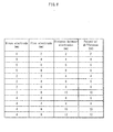
- FIG. 6 is a table illustrating the relationship among the distance from the discharge electrodes to the tip of the discharge prevention plate, the creeping distance between the two discharge electrodes, and the lowest potential difference at which a spark discharge occurs;
- FIG. 7A is a graph illustrating the relationship between the distance between the discharge electrodes 200 and 202 and the amount of discharge current, and indicates the total amount of discharge current flowing from the discharge electrodes 200 and 202 to the intermediate transfer belt 113;
- FIG. 7B is a graph illustrating the relationship between the distance between the discharge electrodes 200 and 202 and the amount of discharge current, and indicates the amount of discharge current flowing from the minus discharge electrode 200 to the intermediate transfer belt 113;
- FIG. 8A is a graph illustrating the non-uniform neutralization observed when only a direct current (DC) voltage of -2400 V was applied to the discharge electrode by the conventional technology that uses only one discharge electrode;
- DC direct current
- FIG. 8B is a graph illustrating the non-uniform neutralization observed when, in addition to the DC voltage of -2400 V, an AC voltage with frequency of 1 kHz and amplitude of 6 kV was applied;
- FIG. 8C is a graph illustrating the non-uniform neutralization observed when, in addition to the DC voltage of -2400 V, an AC voltage with frequency of 1 kHz and amplitude of 10 kV was applied;
- FIG. 9 is a cross-sectional view schematically illustrating the structure of an image creating unit 111 in a modification of the present invention.
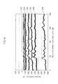
- FIG. 10 is a graph illustrating the charging performance of the charging device 122 in a modification of the present invention.
- FIG. 1 illustrates a main structure of the image forming apparatus in the present embodiment.
- an image forming apparatus 1 is a so-called tandem color MFP (Multi-Function Peripheral) and includes a document reader 100, an image forming unit 110, and a sheet feeder 130.
- the document reader 100 causes an ADF (Automatic Document Feeder) 102 to feed a document placed on a document tray 101, reads the document optically and generates image data.
- the generated image data is stored in a controller 112 which is described below.
- the image forming unit 110 includes image creating units 111Y-111K, a controller 112, an intermediate transfer belt 113, a pair of second transfer rollers 114, a fixing device 115, a pair of paper-ejection rollers 116, a paper tray 117, a cleaning blade 118, a pair of timing rollers 119, and a discharge device 120. Also, the image forming unit 110 is attached with toner cartridges 127Y-127K for supplying toner of colors Y (yellow), M (magenta), C (cyan) and K (black).
- the image creating units 111Y-111K receive supply of toner from the toner cartridges 127Y-127K, respectively, and form toner images of colors Y, M, C and K under the control of the controller 112.
- the image creating unit 111 Y includes, for example, a photosensitive drum 121, a charging device 122, an exposing device 123, a developing device 124, and a cleaning device 125.
- the charging device 122 charges the outer circumferential surface of the photosensitive drum 121 uniformly.
- the exposing device 123 performs an image exposure on the outer circumferential surface of the photosensitive drum 121 in accordance with the image data, thereby forming an electrostatic latent image.
- the developing device 124 supplies toner to the outer circumferential surface of the photosensitive drum 121 so that the electrostatic latent image is developed (an image appears).
- a transfer voltage is applied in advance to a first transfer roller 126, and the toner image on the outer circumferential surface of the photosensitive drum 121 is electrostatically transferred (first transferred) onto the intermediate transfer belt 113 by the electrostatic adsorption.
- the cleaning device 125 scrapes off the remaining toner with a cleaning blade, and neutralizes the outer circumferential surface of the transistor forming layer 121 with a neutralizing lamp.
- the image creating units 111M-111K create toner images of colors M, C and K, respectively.
- the created toner images are first transferred onto the intermediate transfer belt 113 so as to be overlaid with each other.
- the intermediate transfer belt 113 is an endless rotor, and caused to move rotationally in the direction indicated by the arrow A to transport the first transferred toner image to the pair of second transfer rollers 114.
- the sheet feeder 130 includes a sheet feed cassette 131 storing variable sizes of recording sheets S separately, and supplies the recording sheets S to the image forming unit 110.
- the recording sheets S are fed one by one in parallel with the transportation of the toner image by the intermediate transfer belt 113, and are transported to the pair of second transfer rollers 114 via the pair of timing rollers 119.
- the pair of timing rollers 119 is configured to adjust the timing at which each recording sheet S arrives at the pair of second transfer rollers 114.
- the pair of second transfer rollers 114 is composed of a pair of rollers between which a potential difference is created when they receive application of a second transfer voltage.
- the rollers in the pair press each other to form a transfer nip.
- the toner image is transferred electrostatically (second transferred) from the intermediate transfer belt 113 to a recording sheet S.
- the recording sheet S with the toner image transferred thereon is sent to the discharge device 120, where the recording sheet S is neutralized, and then is transported to the fixing device 115. Note that, after the second transfer, the toner remaining on the intermediate transfer belt 113 is further transported in the direction indicated by the arrow A, then scraped off by the cleaning blade 118 and discarded.
- the fixing device 115 heats, while applying pressure to, the toner image such that melted toner image is fixed onto the recording sheet S.
- the recording sheet S with the thermally fixed toner image is ejected onto the paper tray 117 by the pair of paper-ejection rollers 116.
- the controller 112 controls the operation of the image forming apparatus 1 including the above components and an operation panel (not illustrated). Also, the controller 112 transmits and receives image data to/from, and receives jobs from, other devices including a personal computer (PC). The controller 112 further transmits and receives facsimile data via a facsimile line.
- PC personal computer
- the toner remaining on the intermediate transfer belt 113 may be removed by a cleaning brush, a cleaning roller or the like, instead of the cleaning blade.
- FIG. 2 illustrates the configuration and structure of the discharge device 120.
- the discharge device 120 includes a discharge prevention plate 201 and discharge electrodes 200 and 202, where the discharge electrodes 200 and 202 are stuck to different main surfaces of the discharge prevention plate 201.
- An end of each of the discharge electrodes 200 and 202 closer to the intermediate transfer belt 113 is a tapered discharge end.
- the discharge electrode 200 is disposed on the upstream side of the discharge electrode 202 in the recording sheet transportation direction.
- the discharge end of the discharge electrode 200 which is hereinafter referred to as "minus discharge electrode 200" protrudes toward the intermediate transfer belt 113 in the same degree as an end of the discharge prevention plate 201 on the intermediate transfer belt 113 side.
- a minus DC voltage (in the present embodiment, -2000 V) is applied to the minus discharge electrode 200 by a constant voltage source 230.
- the discharge end of the discharge electrode 202 recedes from the intermediate transfer belt 113 than the discharge prevention plate 201.
- a plus DC voltage (in the present embodiment, 4000 V) is applied to the plus discharge electrode 202 by the constant voltage source 230. That is to say, the plus discharge electrode 202 is farther away from the intermediate transfer belt 113 than the minus discharge electrode 200.
- a step 201S is formed in the end of the discharge prevention plate 201 closer to the intermediate transfer belt 113 in the surface portion facing the minus discharge electrode 200.
- the distance between the minus discharge electrode 200 and the intermediate transfer belt 113, and the distance between the discharge prevention plate 201 and the intermediate transfer belt 113 are each 4 mm. Also the distance between the plus discharge electrode 202 and the intermediate transfer belt 113 is 12 mm. With this structure, the recording sheet is prevented from contacting the discharge device 120.
- FIG. 3 is a plan view illustrating the shape of the minus discharge electrode 200.
- saw teeth are formed only on a side that faces toward the intermediate transfer belt 113, and the pitch of the saw teeth is approximately 3 mm.
- the plus discharge electrode 202 has a similar shape.
- the pair of second transfer rollers 114 is composed of an intermediate transfer roller 210 and a transfer roller 211 which are each 30 mm in outer diameter.
- the intermediate transfer belt 113 is wound around the intermediate transfer roller 210.
- the transfer roller 211 is separated from the discharge device 120 by an insulating resin housing 220. Note that the intermediate transfer belt 113 is wound around a roller 221 as well.
- a minus-charged toner is used.
- a plus voltage to the transfer roller 211 By applying a plus voltage to the transfer roller 211, a toner image is second transferred onto the recording sheet.
- the recording sheet on which the toner image has been second transferred is charged with plus electricity.
- the minus discharge electrode 200 neutralizes the recording sheet by discharging minus electricity on the recording sheet.
- the non-uniform neutralization of the recording sheet was evaluated by applying different voltages to the plus discharge electrode 202. Note that an insulating film having been charged to 1000 V was used as the recording sheet, and a voltage of -2000 V was applied to the minus discharge electrode 200. Also, a surface potential detector was used to measure the non-uniform neutralization of the recording sheet.
- FIGs. 4A-4C are graphs illustrating examples of non-uniform neutralization of the recording sheet in the cases where voltages of 0 V, 3000 V and 4000 V were applied to the plus discharge electrode 202, respectively.
- the vertical axis in the graphs represents the surface potential measured by the surface potential detector, and the horizontal axis represents the position of the intermediate transfer roller 210 in the rotational axis direction.
- a voltage of 0 V is applied to the plus discharge electrode 202 ( FIG. 4A ), namely, when the plus discharge electrode 202 is grounded, it is expected that a non-uniform neutralization occurs approximately in the same degree as a neutralization device of a conventional technology that uses only one discharge electrode (corresponding to the minus discharge electrode 200).
- FIGs. 4B and 4C non-uniform neutralizations in smaller degrees than the case of FIG. 4A occurred. This indicates that the discharge device 120 of the present invention provides higher performance in terms of neutralization than the conventional technology.
- the relationship between the discharge current amount and the non-uniform neutralization was evaluated by measuring the amount of discharge current flowing from the discharge electrodes 200 and 202 and the total amount of discharge current, for each case of different values of the potential difference between the discharge electrode 200, 202 and the intermediate transfer belt 113.
- the total amount of discharge current is an amount of current that flows between the discharge device 120 and the intermediate transfer belt 113.
- FIGs. 5A-5C are graphs illustrating the amount of discharge current flowing from the discharge electrodes 200 and 202 and the total amount of discharge current when voltages of 0 V, 3000 V and 4000 V were applied to the plus discharge electrode 202, respectively, in each of the cases which differ from each other by 200 V in potential difference between the discharge electrode 200, 202 and the intermediate transfer belt 113. Note that in the graphs, the vertical axis represents the amount of current, and the horizontal axis represents the potential difference between the discharge electrode 200, 202 and the intermediate transfer belt 113.
- the amount of current flowing into the intermediate transfer belt 113 can be adjusted by guiding as much as increase in the amount of discharge current flowing from the minus discharge electrode 200 to flow into the plus discharge electrode. This makes it possible to control the charging of the recording sheet. It is therefore possible to reduce the non-uniform neutralization of the recording sheet.
- FIG. 6 is a table illustrating the relationship among the distance from the discharge electrodes to the tip of the discharge prevention plate, the creeping distance between the two discharge electrodes, and the lowest potential difference at which a spark discharge occurs. As illustrated in FIG. 6 , the lowest potential difference at which a spark discharge occurs is approximately equal to a value obtained by multiplying 1 kV by the creeping distance [mm] between the two electrodes (the shortest distance along the discharge prevention plate).
- the potential difference at which a spark discharge occurs is determined in accordance with the straight-line distance between the two electrodes, instead of the creeping distance, and thus the two electrodes need to be separated from each other. That is to say, the use of the discharge prevention plate enables the discharge device 120 to be miniaturized.
- FIGs. 7A and 7B are graphs illustrating the relationship between the positions of the discharge electrodes 200 and 202 and the amount of discharge current.
- FIG. 7A illustrates the total amount of discharge current flowing from the discharge electrodes 200 and 202 into the intermediate transfer belt 113.
- FIG. 7B illustrates the amount of discharge current flowing from the minus discharge electrode 200 into the intermediate transfer belt 113. Note that the distance between the minus discharge electrode 200 and the intermediate transfer belt 113 was set to 4 mm. As illustrated in FIG. 7A , regardless of the distance between the discharge electrodes 200 and 202, the total amount of discharge current is constant. On the other hand, as illustrated in FIG.
- the amount of discharge current flowing from the minus discharge electrode 200 into the intermediate transfer belt 113 increases as the distance between the discharge electrodes 200 and 202 increases. That is to say, by separating the minus discharge electrode 200 from the plus discharge electrode 202, it is possible to cause the discharge current to flow into the intermediate transfer belt 113 efficiently.
- the plus discharge electrode 202 when the plus discharge electrode 202 is closer to the intermediate transfer belt 113 than the minus discharge electrode 200, most of the discharge current flowing from the minus discharge electrode 200 flows into the plus discharge electrode 202, and the intermediate transfer belt 113 cannot receive a sufficient amount of discharge current. Also, the distance between the discharge electrodes 200 and 202 has an effect on the strength of the discharge electric field. It is thus necessary to keep a distance that allows for generation of an optimal discharge electric field.
- FIGs. 8A-8C are graphs illustrating the non-uniform neutralization observed in each of the cases which use the conventional technology that uses only one discharge electrode and differ from each other in the applied voltage.
- FIG. 8A illustrates the case where only a DC voltage of -2400 V was applied to the discharge electrode.
- FIG. 8B illustrates the case where, in addition to the DC voltage of -2400 V, an AC voltage with frequency of 1 kHz and amplitude of 6 kV was applied.
- FIG. 8C illustrates the case where, in addition to the DC voltage of -2400 V, an AC voltage with frequency of 1 kHz and amplitude of 10 kV was applied. Note that, needless to say, the waveform of the AC voltages is the sine waveform.
- FIG. 8A a significant level of non-uniform neutralization is observed in the case where only the DC voltage was applied.
- FIG. 8B in the case where an AC voltage with amplitude of 6 kV was applied, a non-uniform neutralization was observed. This indicates that, in this case, the recording sheet was not separated from the intermediate transfer belt 113 with certainty.
- FIG. 8C when an AC voltage with amplitude of 10 kV was applied, non-uniform neutralization was restricted and the recording sheet was prevented from being stuck to the intermediate transfer belt 113, but a significant amount of AC noise occurred. Accordingly, the device of this case cannot be put to practical use.
- the neutralization device of the conventional technology cannot solve the problem to the extent that the device can be put to practical use.
- FIG. 9 is a cross-sectional view schematically illustrating the structure of an image creating unit 111 of the present modification.
- the image creating unit 111 includes the photosensitive drum 121, charging device 122, exposing device 123, developing device 124, and cleaning device 125.
- the charging device 122 includes the discharge prevention plate 201 and discharge electrodes 200 and 202, where the discharge electrodes 200 and 202 having the saw teeth are stuck to the discharge prevention plate 201.
- the discharge electrodes 200 and 202 each receive a supply of DC voltage from the constant voltage source 230 and generate a corona discharge to uniformly charge the outer circumferential surface of the photosensitive drum 121.
- the distance between the minus discharge electrode 200 and the photosensitive drum 121 is 2 mm
- the distance between the plus discharge electrode 202 and the photosensitive drum 121 is 10 mm
- the distance between the discharge prevention plate 201 and the photosensitive drum 121 is 2 mm.
- the exposing device 123 exposes the outer circumferential surface of the photosensitive drum, and thereby forms an electrostatic latent image.
- the developing device 124 supplies toner to the outer circumferential surface of the photosensitive drum 121 so that the electrostatic latent image appears as an image.
- the first transfer roller 126 to which a transfer voltage has been applied, first transfers the toner image on the outer circumferential surface of the photosensitive drum 121 onto the intermediate transfer belt 113 that is moving rotationally in the direction indicated by the arrow A.
- FIG. 10 illustrates graphs indicating the results of the experiment.
- the graphs 1001-1006 indicate non-uniform neutralizations observed when voltages of -1200 V, -1400 V, -1600 V, -1800 V, -2000 V and -2200 V were applied to the minus discharge electrode 200, respectively.
- the conventional technology uses a charging device in which a discharge electrode having saw teeth is surrounded by a stabilizer, and a grid electrode is disposed to face a photosensitive drum.
- the discharge device 120 (the charging device 122 in the present modification) has a thin shape, and thus contributes to the miniaturization of the image creating unit 111.
- the non-uniform neutralization can be restricted by increasing the potential difference between the minus discharge electrode 200 and the plus discharge electrode 202.
- the discharge electrodes 200 and 202 having saw teeth are used.
- the discharge electrodes 200 and 202 may have other shapes than the saw teeth.
- the discharge electrodes 200 and 202 may have different shapes.
- the minus discharge electrode 200 may have saw teeth
- the plus discharge electrode 202 may be plate-like without having saw teeth. The effect of the present invention can be obtained regardless of the shapes of the discharge electrodes 200 and 202.
- a color MFP is used as one example.
- the present invention is not limited to this. The same effect as the above-described one can be obtained when the discharge device of the present invention is loaded in a single-function machine such as a printer, a copier or a facsimile machine instead of an MFP.
Landscapes
- Physics & Mathematics (AREA)
- Engineering & Computer Science (AREA)
- Plasma & Fusion (AREA)
- General Physics & Mathematics (AREA)
- Chemical & Material Sciences (AREA)
- Analytical Chemistry (AREA)
- Electrostatic Charge, Transfer And Separation In Electrography (AREA)
- Elimination Of Static Electricity (AREA)
- Physical Or Chemical Processes And Apparatus (AREA)
Applications Claiming Priority (1)
| Application Number | Priority Date | Filing Date | Title |
|---|---|---|---|
| JP2012043337A JP5655801B2 (ja) | 2012-02-29 | 2012-02-29 | 放電装置 |
Publications (2)
| Publication Number | Publication Date |
|---|---|
| EP2634640A2 true EP2634640A2 (de) | 2013-09-04 |
| EP2634640A3 EP2634640A3 (de) | 2017-11-08 |
Family
ID=47749694
Family Applications (1)
| Application Number | Title | Priority Date | Filing Date |
|---|---|---|---|
| EP13156534.3A Withdrawn EP2634640A3 (de) | 2012-02-29 | 2013-02-25 | Entladevorrichtung |
Country Status (4)
| Country | Link |
|---|---|
| US (1) | US9031467B2 (de) |
| EP (1) | EP2634640A3 (de) |
| JP (1) | JP5655801B2 (de) |
| CN (1) | CN103293905B (de) |
Families Citing this family (1)
| Publication number | Priority date | Publication date | Assignee | Title |
|---|---|---|---|---|
| JP6274142B2 (ja) * | 2015-03-30 | 2018-02-07 | コニカミノルタ株式会社 | 電子写真画像形成方法 |
Citations (1)
| Publication number | Priority date | Publication date | Assignee | Title |
|---|---|---|---|---|
| JPH09114194A (ja) | 1995-10-24 | 1997-05-02 | Konica Corp | コロナ放電装置 |
Family Cites Families (15)
| Publication number | Priority date | Publication date | Assignee | Title |
|---|---|---|---|---|
| JPS577045U (de) * | 1980-06-11 | 1982-01-14 | ||
| US4963738A (en) * | 1986-12-22 | 1990-10-16 | Xerox Corporation | Flat comb-like scorotron charging device |
| US5043579A (en) * | 1990-06-27 | 1991-08-27 | Xerox Corporation | Uniform charging device |
| DE69701060T2 (de) * | 1992-06-04 | 2000-06-08 | Sharp K.K., Osaka | Ladegerät |
| JPH0616128A (ja) * | 1992-06-29 | 1994-01-25 | Jidosha Kiki Co Ltd | 倍力装置の弁機構 |
| JP3225469B2 (ja) * | 1992-10-15 | 2001-11-05 | キヤノン株式会社 | 画像形成装置 |
| JPH06161281A (ja) * | 1992-11-17 | 1994-06-07 | Minolta Camera Co Ltd | 転写分離装置 |
| JP3429860B2 (ja) * | 1994-07-14 | 2003-07-28 | シャープ株式会社 | コロナ放電装置 |
| US6493529B1 (en) * | 1999-07-05 | 2002-12-10 | Ricoh Company, Ltd. | Charging device with walls surrounding the electrodes which reduce ozone emissions |
| US6952548B2 (en) * | 2002-05-31 | 2005-10-04 | Canon Kabushiki Kaisha | Charging apparatus with auxiliary member and image forming apparatus having the charging apparatus |
| JP2004109549A (ja) * | 2002-09-19 | 2004-04-08 | Ricoh Co Ltd | 画像形成装置 |
| JP5220288B2 (ja) | 2006-07-26 | 2013-06-26 | 京セラドキュメントソリューションズ株式会社 | 画像形成装置 |
| JP2008287069A (ja) | 2007-05-18 | 2008-11-27 | Canon Inc | 帯電装置及び画像形成装置 |
| JP5038093B2 (ja) * | 2007-10-24 | 2012-10-03 | キヤノン株式会社 | 画像形成装置または、画像形成装置用の除電装置 |
| JP2010276803A (ja) * | 2009-05-27 | 2010-12-09 | Sharp Corp | 放電素子、該放電素子を備える帯電装置および画像形成装置、ならびに放電素子製造方法 |
-
2012
- 2012-02-29 JP JP2012043337A patent/JP5655801B2/ja not_active Expired - Fee Related
-
2013
- 2013-02-25 EP EP13156534.3A patent/EP2634640A3/de not_active Withdrawn
- 2013-02-27 CN CN201310061792.9A patent/CN103293905B/zh not_active Expired - Fee Related
- 2013-02-27 US US13/779,302 patent/US9031467B2/en not_active Expired - Fee Related
Patent Citations (1)
| Publication number | Priority date | Publication date | Assignee | Title |
|---|---|---|---|---|
| JPH09114194A (ja) | 1995-10-24 | 1997-05-02 | Konica Corp | コロナ放電装置 |
Also Published As
| Publication number | Publication date |
|---|---|
| JP5655801B2 (ja) | 2015-01-21 |
| CN103293905B (zh) | 2016-04-20 |
| EP2634640A3 (de) | 2017-11-08 |
| JP2013178446A (ja) | 2013-09-09 |
| CN103293905A (zh) | 2013-09-11 |
| US20130223884A1 (en) | 2013-08-29 |
| US9031467B2 (en) | 2015-05-12 |
Similar Documents
| Publication | Publication Date | Title |
|---|---|---|
| EP2530531B1 (de) | Bilderzeugungsvorrichtung | |
| JP4175395B2 (ja) | 画像形成装置 | |
| JP2009042399A (ja) | 画像形成装置及び制御方法 | |
| US10295926B2 (en) | Image forming apparatus | |
| US10248043B2 (en) | Image forming apparatus that prevents toner charged with polarity opposite normal charging polarity from being collected | |
| CN115268238A (zh) | 图像形成方法及图像形成装置 | |
| US20120082470A1 (en) | Image forming apparatus | |
| US9354538B2 (en) | Charging device and image forming apparatus incorporating same | |
| KR20130069434A (ko) | 현상 장치, 및 현상 장치의 제어 방법 | |
| US11556077B2 (en) | Image formation apparatus | |
| US9541865B2 (en) | Image forming apparatus with a controller to control an alternating transfer bias | |
| JP2014215529A (ja) | 現像装置及び画像形成装置 | |
| US10289033B2 (en) | Image forming apparatus | |
| US9031467B2 (en) | Discharge device | |
| JP5262704B2 (ja) | 画像形成装置 | |
| JP6452464B2 (ja) | 画像形成装置 | |
| US8948636B2 (en) | Image forming apparatus comprising a plurality of charging rollers | |
| JP2006259198A (ja) | 画像形成装置 | |
| US9395653B2 (en) | Wet-type developing device and wet-type image forming apparatus | |
| US20150286167A1 (en) | Image forming apparatus | |
| JP6390507B2 (ja) | 高圧電源装置、及び、画像形成装置 | |
| JP2015158528A (ja) | 画像形成装置 | |
| JP2008134393A (ja) | 画像形成装置 | |
| US20180210366A1 (en) | Image forming apparatus | |
| JP5253611B2 (ja) | 画像形成装置 |
Legal Events
| Date | Code | Title | Description |
|---|---|---|---|
| PUAI | Public reference made under article 153(3) epc to a published international application that has entered the european phase |
Free format text: ORIGINAL CODE: 0009012 |
|
| AK | Designated contracting states |
Kind code of ref document: A2 Designated state(s): AL AT BE BG CH CY CZ DE DK EE ES FI FR GB GR HR HU IE IS IT LI LT LU LV MC MK MT NL NO PL PT RO RS SE SI SK SM TR |
|
| AX | Request for extension of the european patent |
Extension state: BA ME |
|
| PUAL | Search report despatched |
Free format text: ORIGINAL CODE: 0009013 |
|
| AK | Designated contracting states |
Kind code of ref document: A3 Designated state(s): AL AT BE BG CH CY CZ DE DK EE ES FI FR GB GR HR HU IE IS IT LI LT LU LV MC MK MT NL NO PL PT RO RS SE SI SK SM TR |
|
| AX | Request for extension of the european patent |
Extension state: BA ME |
|
| RIC1 | Information provided on ipc code assigned before grant |
Ipc: G03G 15/00 20060101ALI20171002BHEP Ipc: G03G 15/02 20060101AFI20171002BHEP |
|
| 17P | Request for examination filed |
Effective date: 20180503 |
|
| RBV | Designated contracting states (corrected) |
Designated state(s): AL AT BE BG CH CY CZ DE DK EE ES FI FR GB GR HR HU IE IS IT LI LT LU LV MC MK MT NL NO PL PT RO RS SE SI SK SM TR |
|
| STAA | Information on the status of an ep patent application or granted ep patent |
Free format text: STATUS: THE APPLICATION HAS BEEN WITHDRAWN |
|
| 18W | Application withdrawn |
Effective date: 20180829 |