EP2634471A2 - Kondensatabscheider - Google Patents
Kondensatabscheider Download PDFInfo
- Publication number
- EP2634471A2 EP2634471A2 EP13155251.5A EP13155251A EP2634471A2 EP 2634471 A2 EP2634471 A2 EP 2634471A2 EP 13155251 A EP13155251 A EP 13155251A EP 2634471 A2 EP2634471 A2 EP 2634471A2
- Authority
- EP
- European Patent Office
- Prior art keywords
- condensate
- overpressure
- siphon
- negative pressure
- separator
- Prior art date
- Legal status (The legal status is an assumption and is not a legal conclusion. Google has not performed a legal analysis and makes no representation as to the accuracy of the status listed.)
- Granted
Links
Images


Classifications
-
- F—MECHANICAL ENGINEERING; LIGHTING; HEATING; WEAPONS; BLASTING
- F16—ENGINEERING ELEMENTS AND UNITS; GENERAL MEASURES FOR PRODUCING AND MAINTAINING EFFECTIVE FUNCTIONING OF MACHINES OR INSTALLATIONS; THERMAL INSULATION IN GENERAL
- F16T—STEAM TRAPS OR LIKE APPARATUS FOR DRAINING-OFF LIQUIDS FROM ENCLOSURES PREDOMINANTLY CONTAINING GASES OR VAPOURS
- F16T1/00—Steam traps or like apparatus for draining-off liquids from enclosures predominantly containing gases or vapours, e.g. gas lines, steam lines, containers
- F16T1/34—Steam traps or like apparatus for draining-off liquids from enclosures predominantly containing gases or vapours, e.g. gas lines, steam lines, containers without moving parts other than hand valves, e.g. labyrinth type
-
- F—MECHANICAL ENGINEERING; LIGHTING; HEATING; WEAPONS; BLASTING
- F04—POSITIVE - DISPLACEMENT MACHINES FOR LIQUIDS; PUMPS FOR LIQUIDS OR ELASTIC FLUIDS
- F04F—PUMPING OF FLUID BY DIRECT CONTACT OF ANOTHER FLUID OR BY USING INERTIA OF FLUID TO BE PUMPED; SIPHONS
- F04F10/00—Siphons
- F04F10/02—Gravity-actuated siphons
-
- F—MECHANICAL ENGINEERING; LIGHTING; HEATING; WEAPONS; BLASTING
- F16—ENGINEERING ELEMENTS AND UNITS; GENERAL MEASURES FOR PRODUCING AND MAINTAINING EFFECTIVE FUNCTIONING OF MACHINES OR INSTALLATIONS; THERMAL INSULATION IN GENERAL
- F16T—STEAM TRAPS OR LIKE APPARATUS FOR DRAINING-OFF LIQUIDS FROM ENCLOSURES PREDOMINANTLY CONTAINING GASES OR VAPOURS
- F16T1/00—Steam traps or like apparatus for draining-off liquids from enclosures predominantly containing gases or vapours, e.g. gas lines, steam lines, containers
- F16T1/12—Steam traps or like apparatus for draining-off liquids from enclosures predominantly containing gases or vapours, e.g. gas lines, steam lines, containers with valves controlled by excess or release of pressure
-
- F—MECHANICAL ENGINEERING; LIGHTING; HEATING; WEAPONS; BLASTING
- F24—HEATING; RANGES; VENTILATING
- F24H—FLUID HEATERS, e.g. WATER OR AIR HEATERS, HAVING HEAT-GENERATING MEANS, e.g. HEAT PUMPS, IN GENERAL
- F24H8/00—Fluid heaters characterised by means for extracting latent heat from flue gases by means of condensation
- F24H8/006—Means for removing condensate from the heater
-
- Y—GENERAL TAGGING OF NEW TECHNOLOGICAL DEVELOPMENTS; GENERAL TAGGING OF CROSS-SECTIONAL TECHNOLOGIES SPANNING OVER SEVERAL SECTIONS OF THE IPC; TECHNICAL SUBJECTS COVERED BY FORMER USPC CROSS-REFERENCE ART COLLECTIONS [XRACs] AND DIGESTS
- Y02—TECHNOLOGIES OR APPLICATIONS FOR MITIGATION OR ADAPTATION AGAINST CLIMATE CHANGE
- Y02B—CLIMATE CHANGE MITIGATION TECHNOLOGIES RELATED TO BUILDINGS, e.g. HOUSING, HOUSE APPLIANCES OR RELATED END-USER APPLICATIONS
- Y02B30/00—Energy efficient heating, ventilation or air conditioning [HVAC]
-
- Y—GENERAL TAGGING OF NEW TECHNOLOGICAL DEVELOPMENTS; GENERAL TAGGING OF CROSS-SECTIONAL TECHNOLOGIES SPANNING OVER SEVERAL SECTIONS OF THE IPC; TECHNICAL SUBJECTS COVERED BY FORMER USPC CROSS-REFERENCE ART COLLECTIONS [XRACs] AND DIGESTS
- Y02—TECHNOLOGIES OR APPLICATIONS FOR MITIGATION OR ADAPTATION AGAINST CLIMATE CHANGE
- Y02E—REDUCTION OF GREENHOUSE GAS [GHG] EMISSIONS, RELATED TO ENERGY GENERATION, TRANSMISSION OR DISTRIBUTION
- Y02E60/00—Enabling technologies; Technologies with a potential or indirect contribution to GHG emissions mitigation
- Y02E60/30—Hydrogen technology
- Y02E60/50—Fuel cells
Definitions
- the invention relates to a Kondensatabscheider for a partially under negative pressure and in parts under pressure system, preferably for a heater with exhaust fan.
- Under heater is, for example, a condensing boiler or a combined heat and power plant, in particular a fuel cell understood, in which the heat extraction in the negative pressure and the exhaust pipe is operated in overpressure. Both in the heat extraction and in the exhaust pipe condensate accumulates.
- condensate separators are used, which dissipate the condensing water. Water may then condense in a heater when gas is cooled in a heat exchanger to utilize the accumulated heat. It is important to prevent gas exchange between the heater and the environment, even if there is a negative pressure or overpressure in the heater.
- the condensate separator is provided to separate the condensate formed on the overpressure side of the intake tract of a turbocharged engine on the intercooler.
- This condensate separator has a cylindrical condensate container with a vertically aligned cylinder axis, in which a spherical float is contained, which blocks the connection between the condensate container and the environment or the condensate sink in a lower position.
- an upper float position is furthermore provided, in which the float blocks the connection between the condensate tank and the intake tract. As soon as there is no negative pressure, the float falls back to the lower float position.
- EP 1 739 779 A1 shows a heater based on a fuel cell with multiple condensers.
- the disadvantage, however, is that multiple condensate means a higher cost and a higher installation cost.
- the condensate trap is designed to provide a robust and safe drain of condensate from the overpressure and vacuum areas of the heater without the use of moving parts or even active components such as valves or pumps.
- the siphon also has the goal to realize an intrinsically safe condensate removal, the exhaust gas outlet into the installation room even with a dry or blown siphon can not occur.
- condensate separator This is achieved by a condensate separator according to the features of claim 1. Due to a combination of spec. designed bottle siphon for low pressure condensate and second connection for overpressure condensate in the bottom of the bottle siphon (this creates a tube siphon in the bottle siphon) is made possible to dissipate negative pressure and overpressure condensate with a component.
- a common condensate trap in the form of a siphon collects overpressure and vacuum condensate and conducts everything via one connection. There is no exhaust gas outlet from the overpressure area with blown or dried siphon. No moving parts and no active components are needed.
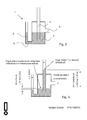
- FIG. 1 shows a heater with a Kondensatabscheider invention.
- FIGS. 2 to 5 show the condensate according to the invention in different operating situations.
- FIG. 6 and 7 show the dimensions of the condensate separator according to the invention.
- the height difference of the connections condensate inlet and outlet must correspond to the maximum negative pressure that occurs, so that the hydrostatic pressure difference can compensate for the pressure difference between overpressure and underpressure areas.
- the siphon holds a sufficient amount of water, so that different pressure differential can be compensated for changing operating conditions.
- the water volume reserved must be greater than the water volume in the vacuum connection pipe at maximum negative pressure plus a minimum amount of water to maintain the siphon function.
- FIG. 8 shows a development of the Kondensatabscheiders invention.
Landscapes
- Engineering & Computer Science (AREA)
- General Engineering & Computer Science (AREA)
- Mechanical Engineering (AREA)
- Physics & Mathematics (AREA)
- Thermal Sciences (AREA)
- Chemical & Material Sciences (AREA)
- Combustion & Propulsion (AREA)
- Fuel Cell (AREA)
- Pressure Vessels And Lids Thereof (AREA)
Abstract
Description
- Die Erfindung betrifft einen Kondensatabscheider für ein in Teilen unter Unterdruck und in Teilen unter Überdruck stehendes System, bevorzugt für ein Heizgerät mit Abgasgebläse. Unter Heizgerät wird beispielsweise ein Brennwertgerät oder eine Kraft-Wärme-Kopplungsanlage, insbesondere eine Brennstoffzelle verstanden, bei der die Wärmeauskopplung im Unterdruck und die Abgasleitung im Überdruck betrieben wird. Sowohl bei der Wärmeauskopplung als auch in der Abgasleitung fällt Kondensat an.
- Hierfür werden Kondensatabscheider eingesetzt, die das kondensierende Wasser ableiten. Wasser kann in einem Heizgerät dann kondensieren, wenn Gas in einem Wärmetauscher zur Nutzung der anfallenden Wärme gekühlt wird. Dabei steht im Vordergrund, einen Gasaustausch zwischen dem Heizgerät und der Umgebung zu verhindern, und zwar auch dann, wenn im Heizgerät ein Unterdruck oder Überdruck herrscht.
- Hierfür sind aus dem Stand der Technik verschiedene Lösungen bekannt. Dies ist beispielsweise die Kondensatableitung über Magnetventile, die das Kondensat gesteuert über zwei wechselseitig öffnende Magnetventile ableitet. Ebenfalls bekannt ist die Verwendung eines druckdichten Kondensat-Auffangbehälters mit einer Pumpe, die angesammeltes Kondensat gegen die Druckdifferenz zur Umgebung abpumpt. Diese beiden Lösungen haben den Nachteil, dass ein hoher apparativer Aufwand getrieben werden muss. Darüber hinaus besteht das Risiko von Betriebsstörungen.
- Außerdem ist es bekannt, das Kondensat über einen U-förmigen Siphon abzuleiten, wobei der Druckausgleich über einen geodätischen Höhenunterschied zwischen der Zu- und Ableitung des Siphons erfolgt. Hierbei ist jedoch problematisch, dass der Höhenunterschied des Siphons nur für einen eingeschränkten Druckdifferenz-Bereich ausgelegt werden kann. Grundsätzlich muss ein Kompromiss zwischen zuverlässiger Kondensatabführung und Unempfindlichkeit gegenüber Druckschwankungen gefunden werden. Dennoch lässt sich ein Leersaugen des Siphons bei Druckstößen nie völlig ausschließen.
- Andererseits ist aus der
JP 10-184471 A - Die Patentanmeldung
EP 1 739 779 A1 zeigt ein Heizgerät auf der Basis einer Brennstoffzelle mit mehreren Kondensatabscheidern. Nachteilig ist jedoch, dass mehrere Kondensatabscheider einen höheren Kostenaufwand und einen höheren Montageaufwand bedeuten. - Es ist daher Aufgabe der Erfindung, für permanent unter Unterdruck stehende Systeme, insbesondere für Brennstoffzellensysteme, einen einfach und kostengünstig aufgebauten, aber zuverlässig funktionierenden Kondensatabscheider bereit zu stellen.
- Der Kondensatabscheider soll ein robuste und sichere Kondensatabfuhr aus Überdruck- und Unterdruckbereichen des Heizgeräts ohne die Verwendung von bewegten Teilen oder gar aktiven Komponenten wie Ventilen oder Pumpen ermöglichen. Der Siphon hat dabei ebenfalls zum Ziel eine eigensichere Kondensatabfuhr zu realisieren, beim dem Abgasaustritt in den Aufstellraum auch bei trockenem oder ausgeblasenem Siphon nicht auftreten kann.
- Dies wird durch einen Kondensatabscheider gemäß den Merkmalen des Anspruchs 1 gelöst. Durch eine Kombination aus spez. ausgelegtem Flaschensiphon für Unterdruckkondensat und zweitem Anschluss für Überdruckkondensat im Grund des Flaschensiphons (dadurch entsteht ein Röhrensiphon im Flaschensiphon) wird ermöglicht Unterdruck- und Überdruckkondensat mit einem Bauteil abzuführen.
- Ein gemeinsamer Kondensatabscheider in Form eines Siphons sammelt Überdruck- und Unterdruckkondensat und führt alles über einen Anschluss ab. Es erfolgt kein Abgasaustritt aus dem Überdruckbereich bei ausgeblasenem oder ausgetrocknetem Siphon. Es werden keine bewegten Teile und keine aktiven Komponenten benötigt.
- Weitere vorteilhafte Ausführungen des erfindungsgemäßen Kondensatabscheiders sowie ein Heizgerät mit einem erfindungsgemäßen Kondensatabscheider sind in den abhängigen Ansprüchen beschrieben.
- Die Erfindung wird nun anhand der Figuren detailliert erläutert.
- Es stellen dar:
-
Figur 1 : Ein Heizgerät mit einem erfindungsgemäßen Kondensatabscheider -
Figur 2 : Einen erfindungsgemäßen Kondensatabscheider in Ruhefunktion -
Figur 3 : Den Kondensatabscheider ausFigur 2 bei Inbetriebnahme -
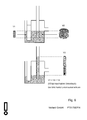
Figur 4 : Den Kondensatabscheider ausFigur 2 im Betrieb -
Figur 5 : Den Kondensatabscheider ausFigur 2 im trockenen Zustand -
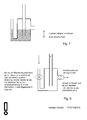
Figur 6 : Die Dimensionierung der Kammervolumina -
Figur 7 : Die Dimensionierung der Auslaufhöhe -
Figur 8 : Eine vorteilhafte Weiterbildung des Wasserabscheiders -
Figur 1 zeigt ein Heizgerät mit einem erfindungsgemäßen Kondensatabscheider. -
Figur 2 bis 5 zeigen den erfindungsgemäßen Kondensatabscheider in verschiedenen Betriebssituationen. - Bei ersten Anwendungen bei denen Kondensat im Unterdruckbereich auftritt, werden z.B. gedichtete Kondensathebepumpen verwendet.
- Durch eine Kombination aus spez. ausgelegtem Flaschensiphon für Unterdruckkondensat und zweitem Anschluss für Überdruckkondensat im Grund des Flaschensiphons (dadurch entsteht ein Röhrensiphon im Flaschensiphon) wird ermöglicht Unterdruck- und Überdruckkondesat mit einem Bauteil abzuführen.
-
Figur 6 und7 zeigen die Dimensionierung des erfindungsgemäßen Kondensatabscheiders. Bei der Auslegung des Flaschensiphons muss die Höhendifferenz der Anschlüsse Kondensatzulauf und -ablauf dem maximal auftretenden Unterdruck entsprechen, damit der hydrostatische Druckunterschied die Druckdifferenz zwischen Überdruck- und Unterdruckbereichen kompensieren kann. Weiterhin besteht die Notwendigkeit, dass der Siphon eine hinreichende Wassermenge vorhält, damit bei wechselnden Betriebszuständen unterschiedliche Differenzdrücke kompensiert werden können. Das vorgehaltene Wasservolumen muss grö-βer dem Wasservolumen im Unterdruckanschlussrohr bei maximalem Unterdruck zzgl. einem Mindestwassermenge zur Aufrecherhaltung der Siphonfunktion sein. -
Figur 8 zeigt eine Weiterbildung des erfindungsgemäßen Kondensatabscheiders. Durch Querschnittsverengungen im Überdruckanschluss und im Kondensatablauf aus dem Siphon die Funktion des Systems auch bei trockenem oder ausgeblasenem Siphon sichergestellt. Die Querschnitte werden so gewählt, dass der Fehlluftstrom, der in den Unterdruckteil des Systems gesaugt wird gering bleibt und den Systembetrieb nicht stört. Die Querschnittsverengungen stellen ebenfalls sicher, dass kein Abgasaustritt aus dem Kondensatanschluss auftreten kann, da das zurückströmende Abgas stets wieder in den Unterdruckteil zurückgesogen wird. -
- 1
- Kondensatabscheider
- 2
- Flaschensiphon
- 3
- Überdruckanschluss
- 4
- Unterdruckanschluss
- 5
- Kondensatablauf
- 6
- Verbindung
Claims (5)
- Kondensatabscheider (1) dadurch gekennzeichnet, dass der Kondensatabscheider (1) einen Überdruckanschluss (3) zum Abscheiden von Kondensat aus einer mit Überdruck beaufschlagten Kondensatquelle und einen Unterdruckanschluss (4) zum Abscheiden von Kondensat aus einer mit Unterdruck beaufschlagten Kondensatquelle aufweist, wobei der Kondensatabscheider (1) durch einen speziell ausgelegtem Flaschensiphon (2) für Unterdruckkondensat gebildet wird, und wobei Überdruckanschluss (3) in Form eines Rohres bis in den Grund des Flaschensiphons (2) geführt ist und im Flaschensiphon (2) ein Röhrensiphon bildet, so dass gemeinsam Unterdruck- und Überdruckkondensat abgeführt werden kann.
- Kondensatabscheider (1) nach Anspruch 1, dadurch gekennzeichnet, dass die Länge des Unterdruckanschlusses (4) so ausgeführt ist, dass die Funktion des Kondensatabscheiders bei einem Unterdruck im Unterdruckanschluss (4) von 10 mbar gegenüber dem Atmosphärendruck gewährleistet ist.
- Kondensatabscheider (1) nach Anspruch 1, dadurch gekennzeichnet, dass die Länge des Überdruckanschlusses (3) so auf die Länge des Unterdruckanschlusses (4) und die Höhe des Flaschensiphons (2) abgestimmt ist, dass die Funktion des Kondensatabscheiders bei einem Überdruck von 50 mbar gegenüber dem Atmosphärendruck gewährleistet ist.
- Kondensatabscheider nach einem der Ansprüche 1 bis 3, dadurch gekennzeichnet, dass der Überdruckanschluss (3) und/oder der Unterdruckanschluss (4) und/oder der Kondesantablauf (5) eine Drosselblende aufweist.
- Heizgerät, bevorzugt ein Brennwertgerät oder eine Kraft-Wärme-Kopplungsanlage, besonders bevorzugt eine Brennstoffzelle mit einem Kondensatabscheider nach einem der Ansprüche 1 bis 4.
Applications Claiming Priority (1)
| Application Number | Priority Date | Filing Date | Title |
|---|---|---|---|
| DE102012003950A DE102012003950A1 (de) | 2012-03-01 | 2012-03-01 | Kondensatabscheider |
Publications (3)
| Publication Number | Publication Date |
|---|---|
| EP2634471A2 true EP2634471A2 (de) | 2013-09-04 |
| EP2634471A3 EP2634471A3 (de) | 2017-08-09 |
| EP2634471B1 EP2634471B1 (de) | 2019-09-18 |
Family
ID=47747436
Family Applications (1)
| Application Number | Title | Priority Date | Filing Date |
|---|---|---|---|
| EP13155251.5A Active EP2634471B1 (de) | 2012-03-01 | 2013-02-14 | Kondensatabscheider |
Country Status (2)
| Country | Link |
|---|---|
| EP (1) | EP2634471B1 (de) |
| DE (1) | DE102012003950A1 (de) |
Cited By (2)
| Publication number | Priority date | Publication date | Assignee | Title |
|---|---|---|---|---|
| WO2016142178A1 (de) * | 2015-03-09 | 2016-09-15 | Robert Bosch Gmbh | Anschluss für kondensatablauf eines heizgeräts |
| FR3066011A1 (fr) * | 2017-05-02 | 2018-11-09 | S.A.T.E. Societe D'applications Thermiques Europeenne | Chauffe-eau thermodynamique |
Families Citing this family (1)
| Publication number | Priority date | Publication date | Assignee | Title |
|---|---|---|---|---|
| DE102023100254A1 (de) * | 2023-01-06 | 2024-07-11 | Solvis GmbH | Heizungsanlage und Siphon |
Citations (2)
| Publication number | Priority date | Publication date | Assignee | Title |
|---|---|---|---|---|
| JPH10184471A (ja) | 1996-12-24 | 1998-07-14 | Tokyo Gas Co Ltd | ドレーントラップ |
| EP1739779A1 (de) | 2005-06-30 | 2007-01-03 | Viessmann Werke GmbH & Co. KG | Gerät zur Bereitstellung thermischer und elektrischer Energie |
Family Cites Families (7)
| Publication number | Priority date | Publication date | Assignee | Title |
|---|---|---|---|---|
| US1002814A (en) * | 1910-05-20 | 1911-09-05 | Allis Chalmers | Barometric condenser. |
| US4611622A (en) * | 1984-11-13 | 1986-09-16 | Intertherm Inc. | Drain for condensate from flue gas |
| US4729328A (en) * | 1987-04-23 | 1988-03-08 | Rheem Manufacturing Company | Trap assembly for a condensing fossil fuel furnace |
| US5379749A (en) * | 1993-08-16 | 1995-01-10 | Carrier Corporation | Condensate trap for multi-poise furnace |
| US5704343A (en) * | 1996-09-11 | 1998-01-06 | American Standard Inc. | Furnace condensate trap |
| AT409536B (de) * | 2000-04-17 | 2002-09-25 | Vaillant Gmbh | Einrichtung zur abfuhr von kondensat |
| JP2008115546A (ja) * | 2006-11-01 | 2008-05-22 | Bridgestone Corp | 排水トラップ |
-
2012
- 2012-03-01 DE DE102012003950A patent/DE102012003950A1/de not_active Withdrawn
-
2013
- 2013-02-14 EP EP13155251.5A patent/EP2634471B1/de active Active
Patent Citations (2)
| Publication number | Priority date | Publication date | Assignee | Title |
|---|---|---|---|---|
| JPH10184471A (ja) | 1996-12-24 | 1998-07-14 | Tokyo Gas Co Ltd | ドレーントラップ |
| EP1739779A1 (de) | 2005-06-30 | 2007-01-03 | Viessmann Werke GmbH & Co. KG | Gerät zur Bereitstellung thermischer und elektrischer Energie |
Cited By (3)
| Publication number | Priority date | Publication date | Assignee | Title |
|---|---|---|---|---|
| WO2016142178A1 (de) * | 2015-03-09 | 2016-09-15 | Robert Bosch Gmbh | Anschluss für kondensatablauf eines heizgeräts |
| EP3805662A3 (de) * | 2015-03-09 | 2021-08-11 | Robert Bosch GmbH | Anschluss für kondensatablauf eines heizgeräts |
| FR3066011A1 (fr) * | 2017-05-02 | 2018-11-09 | S.A.T.E. Societe D'applications Thermiques Europeenne | Chauffe-eau thermodynamique |
Also Published As
| Publication number | Publication date |
|---|---|
| EP2634471B1 (de) | 2019-09-18 |
| EP2634471A3 (de) | 2017-08-09 |
| DE102012003950A1 (de) | 2013-09-05 |
Similar Documents
| Publication | Publication Date | Title |
|---|---|---|
| EP4194769A1 (de) | Kältemittelanlage sowie kältemittelmodul | |
| DE102011005916A1 (de) | Druckausgleichelement, Gehäuse ein Druckausgleichelement aufweisend, Lithium Ionen-Akkumulator sowie Kraftfahrzeug | |
| EP2634471B1 (de) | Kondensatabscheider | |
| EP4496942A1 (de) | Flüssigkeitsabscheidevorrichtung für ein kompressorsystem und kompressorsystem mit einer solchen flüssigkeitsabscheidevorrichtung | |
| WO2010003802A1 (de) | Konditioniermodul zum konditionieren von an sich ruhenden flüssigkeiten | |
| DE102013221447A1 (de) | Kühlsystem für ein Kraftfahrzeug | |
| WO2016055373A1 (de) | Entlüftungsmodul für einen verbrennungsmotor | |
| WO2012052226A2 (de) | Vorrichtung zur abwärmenutzung | |
| WO2021213778A1 (de) | Entlüftungseinrichtung | |
| EP2307739A1 (de) | Pumpe nach art einer wasserstrahlpumpe sowie verfahren zu deren betrieb | |
| DE102012006518A1 (de) | Kühlmittelkreislauf eines Fahrzeugs | |
| WO2001044712A1 (de) | Verfahren zum ableiten von kondensat und kondensatableiter | |
| EP2447591B1 (de) | Kondensatabscheider für Brennstoffzellensystem im Unterdruckbetrieb | |
| DE102005038896B4 (de) | Flüssigkeitsabschneider und dessen Verwendung | |
| DE102020112376A1 (de) | Wärmepumpen-Anlage | |
| DE102014200001A1 (de) | Vorrichtung zum Ausbringen von Kondenswasser aus einem Gehäuse sowie Gehäuse mit einer solchen Vorrichtung | |
| DE102009060588B3 (de) | Vorrichtung zum Ablauf von Flüssigkeiten | |
| DE102011122313A1 (de) | Kühlmittel-Ausgleichsbehälter-System | |
| AT28130B (de) | Kondensatoranlage mit Zentrifugalpumpen zum Absaugen des Kondensates. | |
| DE102016221255A1 (de) | Abwärmenutzungskreislauf, insbesondere für ein Kraftfahrzeug | |
| AT512522A4 (de) | Luftbefeuchter | |
| DE102013106329B4 (de) | Verfahren und Anordnung zum Evakuieren eines Rohrleitungssystems | |
| DE102024105599A1 (de) | Siphon mit Sicherheitssperrvorrichtung | |
| WO2019134944A1 (de) | Saugfiltervorrichtung mit luftabscheidung | |
| DE102014010261B4 (de) | Kühlmittelsystem |
Legal Events
| Date | Code | Title | Description |
|---|---|---|---|
| PUAI | Public reference made under article 153(3) epc to a published international application that has entered the european phase |
Free format text: ORIGINAL CODE: 0009012 |
|
| AK | Designated contracting states |
Kind code of ref document: A2 Designated state(s): AL AT BE BG CH CY CZ DE DK EE ES FI FR GB GR HR HU IE IS IT LI LT LU LV MC MK MT NL NO PL PT RO RS SE SI SK SM TR |
|
| AX | Request for extension of the european patent |
Extension state: BA ME |
|
| PUAL | Search report despatched |
Free format text: ORIGINAL CODE: 0009013 |
|
| AK | Designated contracting states |
Kind code of ref document: A3 Designated state(s): AL AT BE BG CH CY CZ DE DK EE ES FI FR GB GR HR HU IE IS IT LI LT LU LV MC MK MT NL NO PL PT RO RS SE SI SK SM TR |
|
| AX | Request for extension of the european patent |
Extension state: BA ME |
|
| RIC1 | Information provided on ipc code assigned before grant |
Ipc: F16T 1/34 20060101AFI20170630BHEP Ipc: F24H 8/00 20060101ALI20170630BHEP Ipc: F04F 10/02 20060101ALI20170630BHEP Ipc: F16T 1/12 20060101ALI20170630BHEP |
|
| STAA | Information on the status of an ep patent application or granted ep patent |
Free format text: STATUS: REQUEST FOR EXAMINATION WAS MADE |
|
| 17P | Request for examination filed |
Effective date: 20180209 |
|
| RBV | Designated contracting states (corrected) |
Designated state(s): AL AT BE BG CH CY CZ DE DK EE ES FI FR GB GR HR HU IE IS IT LI LT LU LV MC MK MT NL NO PL PT RO RS SE SI SK SM TR |
|
| GRAP | Despatch of communication of intention to grant a patent |
Free format text: ORIGINAL CODE: EPIDOSNIGR1 |
|
| STAA | Information on the status of an ep patent application or granted ep patent |
Free format text: STATUS: GRANT OF PATENT IS INTENDED |
|
| INTG | Intention to grant announced |
Effective date: 20190520 |
|
| GRAS | Grant fee paid |
Free format text: ORIGINAL CODE: EPIDOSNIGR3 |
|
| GRAA | (expected) grant |
Free format text: ORIGINAL CODE: 0009210 |
|
| STAA | Information on the status of an ep patent application or granted ep patent |
Free format text: STATUS: THE PATENT HAS BEEN GRANTED |
|
| AK | Designated contracting states |
Kind code of ref document: B1 Designated state(s): AL AT BE BG CH CY CZ DE DK EE ES FI FR GB GR HR HU IE IS IT LI LT LU LV MC MK MT NL NO PL PT RO RS SE SI SK SM TR |
|
| REG | Reference to a national code |
Ref country code: GB Ref legal event code: FG4D Free format text: NOT ENGLISH |
|
| REG | Reference to a national code |
Ref country code: CH Ref legal event code: EP |
|
| REG | Reference to a national code |
Ref country code: DE Ref legal event code: R096 Ref document number: 502013013595 Country of ref document: DE |
|
| REG | Reference to a national code |
Ref country code: AT Ref legal event code: REF Ref document number: 1181750 Country of ref document: AT Kind code of ref document: T Effective date: 20191015 |
|
| REG | Reference to a national code |
Ref country code: IE Ref legal event code: FG4D Free format text: LANGUAGE OF EP DOCUMENT: GERMAN |
|
| REG | Reference to a national code |
Ref country code: NL Ref legal event code: MP Effective date: 20190918 |
|
| PG25 | Lapsed in a contracting state [announced via postgrant information from national office to epo] |
Ref country code: NO Free format text: LAPSE BECAUSE OF FAILURE TO SUBMIT A TRANSLATION OF THE DESCRIPTION OR TO PAY THE FEE WITHIN THE PRESCRIBED TIME-LIMIT Effective date: 20191218 Ref country code: HR Free format text: LAPSE BECAUSE OF FAILURE TO SUBMIT A TRANSLATION OF THE DESCRIPTION OR TO PAY THE FEE WITHIN THE PRESCRIBED TIME-LIMIT Effective date: 20190918 Ref country code: SE Free format text: LAPSE BECAUSE OF FAILURE TO SUBMIT A TRANSLATION OF THE DESCRIPTION OR TO PAY THE FEE WITHIN THE PRESCRIBED TIME-LIMIT Effective date: 20190918 Ref country code: FI Free format text: LAPSE BECAUSE OF FAILURE TO SUBMIT A TRANSLATION OF THE DESCRIPTION OR TO PAY THE FEE WITHIN THE PRESCRIBED TIME-LIMIT Effective date: 20190918 Ref country code: LT Free format text: LAPSE BECAUSE OF FAILURE TO SUBMIT A TRANSLATION OF THE DESCRIPTION OR TO PAY THE FEE WITHIN THE PRESCRIBED TIME-LIMIT Effective date: 20190918 Ref country code: BG Free format text: LAPSE BECAUSE OF FAILURE TO SUBMIT A TRANSLATION OF THE DESCRIPTION OR TO PAY THE FEE WITHIN THE PRESCRIBED TIME-LIMIT Effective date: 20191218 |
|
| REG | Reference to a national code |
Ref country code: LT Ref legal event code: MG4D |
|
| PG25 | Lapsed in a contracting state [announced via postgrant information from national office to epo] |
Ref country code: GR Free format text: LAPSE BECAUSE OF FAILURE TO SUBMIT A TRANSLATION OF THE DESCRIPTION OR TO PAY THE FEE WITHIN THE PRESCRIBED TIME-LIMIT Effective date: 20191219 Ref country code: LV Free format text: LAPSE BECAUSE OF FAILURE TO SUBMIT A TRANSLATION OF THE DESCRIPTION OR TO PAY THE FEE WITHIN THE PRESCRIBED TIME-LIMIT Effective date: 20190918 Ref country code: AL Free format text: LAPSE BECAUSE OF FAILURE TO SUBMIT A TRANSLATION OF THE DESCRIPTION OR TO PAY THE FEE WITHIN THE PRESCRIBED TIME-LIMIT Effective date: 20190918 Ref country code: RS Free format text: LAPSE BECAUSE OF FAILURE TO SUBMIT A TRANSLATION OF THE DESCRIPTION OR TO PAY THE FEE WITHIN THE PRESCRIBED TIME-LIMIT Effective date: 20190918 |
|
| PG25 | Lapsed in a contracting state [announced via postgrant information from national office to epo] |
Ref country code: NL Free format text: LAPSE BECAUSE OF FAILURE TO SUBMIT A TRANSLATION OF THE DESCRIPTION OR TO PAY THE FEE WITHIN THE PRESCRIBED TIME-LIMIT Effective date: 20190918 Ref country code: RO Free format text: LAPSE BECAUSE OF FAILURE TO SUBMIT A TRANSLATION OF THE DESCRIPTION OR TO PAY THE FEE WITHIN THE PRESCRIBED TIME-LIMIT Effective date: 20190918 Ref country code: PL Free format text: LAPSE BECAUSE OF FAILURE TO SUBMIT A TRANSLATION OF THE DESCRIPTION OR TO PAY THE FEE WITHIN THE PRESCRIBED TIME-LIMIT Effective date: 20190918 Ref country code: ES Free format text: LAPSE BECAUSE OF FAILURE TO SUBMIT A TRANSLATION OF THE DESCRIPTION OR TO PAY THE FEE WITHIN THE PRESCRIBED TIME-LIMIT Effective date: 20190918 Ref country code: EE Free format text: LAPSE BECAUSE OF FAILURE TO SUBMIT A TRANSLATION OF THE DESCRIPTION OR TO PAY THE FEE WITHIN THE PRESCRIBED TIME-LIMIT Effective date: 20190918 Ref country code: IT Free format text: LAPSE BECAUSE OF FAILURE TO SUBMIT A TRANSLATION OF THE DESCRIPTION OR TO PAY THE FEE WITHIN THE PRESCRIBED TIME-LIMIT Effective date: 20190918 Ref country code: PT Free format text: LAPSE BECAUSE OF FAILURE TO SUBMIT A TRANSLATION OF THE DESCRIPTION OR TO PAY THE FEE WITHIN THE PRESCRIBED TIME-LIMIT Effective date: 20200120 |
|
| PG25 | Lapsed in a contracting state [announced via postgrant information from national office to epo] |
Ref country code: IS Free format text: LAPSE BECAUSE OF FAILURE TO SUBMIT A TRANSLATION OF THE DESCRIPTION OR TO PAY THE FEE WITHIN THE PRESCRIBED TIME-LIMIT Effective date: 20200224 Ref country code: SM Free format text: LAPSE BECAUSE OF FAILURE TO SUBMIT A TRANSLATION OF THE DESCRIPTION OR TO PAY THE FEE WITHIN THE PRESCRIBED TIME-LIMIT Effective date: 20190918 Ref country code: SK Free format text: LAPSE BECAUSE OF FAILURE TO SUBMIT A TRANSLATION OF THE DESCRIPTION OR TO PAY THE FEE WITHIN THE PRESCRIBED TIME-LIMIT Effective date: 20190918 Ref country code: CZ Free format text: LAPSE BECAUSE OF FAILURE TO SUBMIT A TRANSLATION OF THE DESCRIPTION OR TO PAY THE FEE WITHIN THE PRESCRIBED TIME-LIMIT Effective date: 20190918 |
|
| REG | Reference to a national code |
Ref country code: DE Ref legal event code: R097 Ref document number: 502013013595 Country of ref document: DE |
|
| PLBE | No opposition filed within time limit |
Free format text: ORIGINAL CODE: 0009261 |
|
| STAA | Information on the status of an ep patent application or granted ep patent |
Free format text: STATUS: NO OPPOSITION FILED WITHIN TIME LIMIT |
|
| PG2D | Information on lapse in contracting state deleted |
Ref country code: IS |
|
| PG25 | Lapsed in a contracting state [announced via postgrant information from national office to epo] |
Ref country code: DK Free format text: LAPSE BECAUSE OF FAILURE TO SUBMIT A TRANSLATION OF THE DESCRIPTION OR TO PAY THE FEE WITHIN THE PRESCRIBED TIME-LIMIT Effective date: 20190918 Ref country code: IS Free format text: LAPSE BECAUSE OF FAILURE TO SUBMIT A TRANSLATION OF THE DESCRIPTION OR TO PAY THE FEE WITHIN THE PRESCRIBED TIME-LIMIT Effective date: 20200119 |
|
| 26N | No opposition filed |
Effective date: 20200619 |
|
| PG25 | Lapsed in a contracting state [announced via postgrant information from national office to epo] |
Ref country code: SI Free format text: LAPSE BECAUSE OF FAILURE TO SUBMIT A TRANSLATION OF THE DESCRIPTION OR TO PAY THE FEE WITHIN THE PRESCRIBED TIME-LIMIT Effective date: 20190918 |
|
| REG | Reference to a national code |
Ref country code: CH Ref legal event code: PL |
|
| GBPC | Gb: european patent ceased through non-payment of renewal fee |
Effective date: 20200214 |
|
| REG | Reference to a national code |
Ref country code: BE Ref legal event code: MM Effective date: 20200229 |
|
| PG25 | Lapsed in a contracting state [announced via postgrant information from national office to epo] |
Ref country code: MC Free format text: LAPSE BECAUSE OF FAILURE TO SUBMIT A TRANSLATION OF THE DESCRIPTION OR TO PAY THE FEE WITHIN THE PRESCRIBED TIME-LIMIT Effective date: 20190918 Ref country code: LU Free format text: LAPSE BECAUSE OF NON-PAYMENT OF DUE FEES Effective date: 20200214 |
|
| PG25 | Lapsed in a contracting state [announced via postgrant information from national office to epo] |
Ref country code: LI Free format text: LAPSE BECAUSE OF NON-PAYMENT OF DUE FEES Effective date: 20200229 Ref country code: CH Free format text: LAPSE BECAUSE OF NON-PAYMENT OF DUE FEES Effective date: 20200229 |
|
| PG25 | Lapsed in a contracting state [announced via postgrant information from national office to epo] |
Ref country code: FR Free format text: LAPSE BECAUSE OF NON-PAYMENT OF DUE FEES Effective date: 20200229 Ref country code: IE Free format text: LAPSE BECAUSE OF NON-PAYMENT OF DUE FEES Effective date: 20200214 Ref country code: GB Free format text: LAPSE BECAUSE OF NON-PAYMENT OF DUE FEES Effective date: 20200214 |
|
| PG25 | Lapsed in a contracting state [announced via postgrant information from national office to epo] |
Ref country code: BE Free format text: LAPSE BECAUSE OF NON-PAYMENT OF DUE FEES Effective date: 20200229 |
|
| REG | Reference to a national code |
Ref country code: AT Ref legal event code: MM01 Ref document number: 1181750 Country of ref document: AT Kind code of ref document: T Effective date: 20200214 |
|
| PG25 | Lapsed in a contracting state [announced via postgrant information from national office to epo] |
Ref country code: AT Free format text: LAPSE BECAUSE OF NON-PAYMENT OF DUE FEES Effective date: 20200214 |
|
| PGFP | Annual fee paid to national office [announced via postgrant information from national office to epo] |
Ref country code: DE Payment date: 20210202 Year of fee payment: 9 |
|
| PG25 | Lapsed in a contracting state [announced via postgrant information from national office to epo] |
Ref country code: TR Free format text: LAPSE BECAUSE OF FAILURE TO SUBMIT A TRANSLATION OF THE DESCRIPTION OR TO PAY THE FEE WITHIN THE PRESCRIBED TIME-LIMIT Effective date: 20190918 Ref country code: MT Free format text: LAPSE BECAUSE OF FAILURE TO SUBMIT A TRANSLATION OF THE DESCRIPTION OR TO PAY THE FEE WITHIN THE PRESCRIBED TIME-LIMIT Effective date: 20190918 Ref country code: CY Free format text: LAPSE BECAUSE OF FAILURE TO SUBMIT A TRANSLATION OF THE DESCRIPTION OR TO PAY THE FEE WITHIN THE PRESCRIBED TIME-LIMIT Effective date: 20190918 |
|
| PG25 | Lapsed in a contracting state [announced via postgrant information from national office to epo] |
Ref country code: MK Free format text: LAPSE BECAUSE OF FAILURE TO SUBMIT A TRANSLATION OF THE DESCRIPTION OR TO PAY THE FEE WITHIN THE PRESCRIBED TIME-LIMIT Effective date: 20190918 |
|
| REG | Reference to a national code |
Ref country code: DE Ref legal event code: R119 Ref document number: 502013013595 Country of ref document: DE |
|
| PG25 | Lapsed in a contracting state [announced via postgrant information from national office to epo] |
Ref country code: DE Free format text: LAPSE BECAUSE OF NON-PAYMENT OF DUE FEES Effective date: 20220901 |