EP2634460B1 - Schiff mit einer Schottabdichtung im Bereich von Wellendurchführungen - Google Patents
Schiff mit einer Schottabdichtung im Bereich von Wellendurchführungen Download PDFInfo
- Publication number
- EP2634460B1 EP2634460B1 EP20130000507 EP13000507A EP2634460B1 EP 2634460 B1 EP2634460 B1 EP 2634460B1 EP 20130000507 EP20130000507 EP 20130000507 EP 13000507 A EP13000507 A EP 13000507A EP 2634460 B1 EP2634460 B1 EP 2634460B1
- Authority
- EP
- European Patent Office
- Prior art keywords
- sealing rings
- shaft
- piston
- segments
- ship
- Prior art date
- Legal status (The legal status is an assumption and is not a legal conclusion. Google has not performed a legal analysis and makes no representation as to the accuracy of the status listed.)
- Not-in-force
Links
- 238000007789 sealing Methods 0.000 claims description 45
- 230000006835 compression Effects 0.000 claims description 9
- 238000007906 compression Methods 0.000 claims description 9
- 230000004913 activation Effects 0.000 claims description 2
- 238000001514 detection method Methods 0.000 description 2
- 238000006073 displacement reaction Methods 0.000 description 2
- 238000013022 venting Methods 0.000 description 2
- XLYOFNOQVPJJNP-UHFFFAOYSA-N water Substances O XLYOFNOQVPJJNP-UHFFFAOYSA-N 0.000 description 2
- 230000002411 adverse Effects 0.000 description 1
- 230000005540 biological transmission Effects 0.000 description 1
- 230000015572 biosynthetic process Effects 0.000 description 1
- 230000003750 conditioning effect Effects 0.000 description 1
- 230000007547 defect Effects 0.000 description 1
- 238000010586 diagram Methods 0.000 description 1
- 230000000694 effects Effects 0.000 description 1
- 238000005755 formation reaction Methods 0.000 description 1
- 230000020169 heat generation Effects 0.000 description 1
- 230000007257 malfunction Effects 0.000 description 1
Images


Classifications
-
- B—PERFORMING OPERATIONS; TRANSPORTING
- B63—SHIPS OR OTHER WATERBORNE VESSELS; RELATED EQUIPMENT
- B63H—MARINE PROPULSION OR STEERING
- B63H23/00—Transmitting power from propulsion power plant to propulsive elements
- B63H23/32—Other parts
- B63H23/321—Bearings or seals specially adapted for propeller shafts
-
- B—PERFORMING OPERATIONS; TRANSPORTING
- B63—SHIPS OR OTHER WATERBORNE VESSELS; RELATED EQUIPMENT
- B63H—MARINE PROPULSION OR STEERING
- B63H23/00—Transmitting power from propulsion power plant to propulsive elements
- B63H23/32—Other parts
- B63H23/36—Shaft tubes
-
- F—MECHANICAL ENGINEERING; LIGHTING; HEATING; WEAPONS; BLASTING
- F16—ENGINEERING ELEMENTS AND UNITS; GENERAL MEASURES FOR PRODUCING AND MAINTAINING EFFECTIVE FUNCTIONING OF MACHINES OR INSTALLATIONS; THERMAL INSULATION IN GENERAL
- F16J—PISTONS; CYLINDERS; SEALINGS
- F16J15/00—Sealings
- F16J15/16—Sealings between relatively-moving surfaces
-
- B—PERFORMING OPERATIONS; TRANSPORTING
- B63—SHIPS OR OTHER WATERBORNE VESSELS; RELATED EQUIPMENT
- B63H—MARINE PROPULSION OR STEERING
- B63H23/00—Transmitting power from propulsion power plant to propulsive elements
- B63H23/32—Other parts
- B63H23/321—Bearings or seals specially adapted for propeller shafts
- B63H2023/327—Sealings specially adapted for propeller shafts or stern tubes
Definitions
- the invention relates to a ship with a bulkhead seal according to the preamble of claim 1 and as it is known from the document GB 2140880 A is known. Formations of this type are known in various embodiments for sealing bulkheads with recorded waves. In this case there is the defect that due to the system on the shaft wear occurs and despite the adjustability of the sealing rings partially occurring radial shaft displacements are only partially controlled. In addition, a noiseless arrangement is not feasible, with noises are introduced into the ship's structure and also heat generation occurs.
- the object of the invention is to eliminate the disadvantages of the previous arrangements by a simple design and to activate the seal in case of need for water detection and failure of the power supply and thereby ensure long service life without adverse effects.
- piston chamber can be acted upon in normal operation by the supplied pressure medium via a control unit for decoupling the seal by lifting the sealing rings and occurring malfunctions activation of the sealing rings for sealing by pressure relief of the piston chamber is automatically adjustable.
- the pressure medium is formed by compressed air.
- the sealing rings have for receiving corresponding projections of the associated pressure ring guide grooves.
- each sealing ring is formed of six segments.
- a two-part housing 1 is attached to a bulkhead not shown in detail of a ship via screws 2.
- the housing 1 has a passage opening 3 for receiving a shaft 4th
- the shaft 4 are in the housing 1 adjustable parallel sealing rings 5, 6 associated with individual segments 7, which are adjustable in diameter over star tenings of corresponding receptacles 8 and guide elements 9 for conditioning and sealing to the shaft 4.
- guide grooves 10 for receiving a likewise segmented pressure ring 11 is arranged, which presses the sealing rings 5, 6 for engagement with the shaft 4 via recorded ring springs 12 as tension springs.
- each segment 7 of the parallel associated sealing rings 5, 6 associated with an adjusting device 15 acts.
- outwardly guided piston rod 16 is arranged, which engages on a driver element 17 in the region of the sealing rings 5, 6 in associated receptacles 18 of the segments 7 on both sides for lifting, wherein the piston rod 16 above the sealing rings 5, the sixth is connected in a piston chamber 19 with an adjustable piston 20.
- a compression spring 21 is arranged, which leads the piston 20 in the direction of the shaft 4 in the pressureless state of the piston chamber 19.
- the piston chamber 19 is acted upon in this embodiment via a port 27 with compressed air, wherein the control is carried out via a control unit 22, the corresponding valves 23, 24 controls.
- the control unit 22 is additionally controlled by a sensor 25 which interrupts the compressed air supply via the valve 24 in the case of water detection and causes the venting of the piston chamber 19 via the valve 23.
- the venting of the control chamber 19 is also brought about via the control unit 22 and an energy monitor 26.
Landscapes
- Engineering & Computer Science (AREA)
- Mechanical Engineering (AREA)
- Chemical & Material Sciences (AREA)
- Combustion & Propulsion (AREA)
- Ocean & Marine Engineering (AREA)
- General Engineering & Computer Science (AREA)
- Sealing Devices (AREA)
- Fluid-Damping Devices (AREA)
Description
- Die Erfindung bezieht sich auf ein Schiff mit einer Schottabdichtung gemäß dem Oberbegriff des Anspruchs 1 und wie es aus dem Dokument
GB 2140880 A - Die Aufgabe der Erfindung ist es, durch eine einfache Ausbildung die Nachteile der bisherigen Anordnungen auszuschalten und die Abdichtung im Bedarfsfall bei Wasserdetektion und Ausfall der Energieversorgung zu aktivieren und dadurch große Standzeiten ohne Beeinträchtigungen zu gewährleisten.
- Die Lösung dieser Aufgabe erfolgt erfindungsgemäß dadurch, dass radial zur Welle wirkende Verstelleinrichtungen den einzelnen Segmenten der Dichtringe im Gehäuse zugeordnet sind, wobei jede Verstelleinrichtung durch eine zwischen den Dichtringen nach außen geführte Kolbenstange aufweist, die am Ende ein Mitnehmerelement trägt, das in zugeordnete Aufnahmen der Segmente der Dichtringe zum Anheben eingreift und oberhalb der Dichtringe eine Kolbenkammer mit einem verstellbaren Kolben am Ende der Kolbenstange angeordnet ist und über ein steuerbares Druckmedium der Kolben in eine Endstellung der Kolbenkammer zum Anheben der Segmente der Dichtringe im Abstand zur Welle gegen die Kraft einer oberhalb des Kolbens zugeordneten Druckfeder und der Ringfedern der Druckringe einstellbar ist und im drucklosen Zustand der Kolben über die Druckfeder nach unten verstellbar ist und die Ringfedern die Segmente der Dichtringe über den Druckring zur dichtenden Anlage an die Welle anlegbar sind.
- Hierdurch wird im Normalbetrieb eine reibungslose Abdichtung ohne Verschleiß mit geräuschlosem Lauf ohne Übertragung von der Welle in die Schiffsstruktur ermöglicht und es treten auch keine Berührungen bei radialen Wellenverlagerungen auf. Zusätzlich ist kein Limit für Wellendrehzahlen gegeben.
- Eine vorteilhafte Ausbildung besteht darin, dass die Kolbenkammer im Normalbetrieb durch das zugeführte Druckmedium über eine Steuereinheit zur Entkopplung der Dichtung durch Anheben der Dichtringe beaufschlagbar ist und bei auftretenden Störungen eine Aktivierung der Dichtringe zur Dichtung durch Druckentlastung der Kolbenkammer selbsttätig einstellbar ist.
- Ferner wird vorgeschlagen, dass das Druckmedium durch Druckluft gebildet ist.
- In Ausgestaltung der Erfindung ist vorgesehen, dass die Dichtringe zur Aufnahme korrespondierender Vorsprünge des zugeordneten Druckringes Führungsnuten aufweisen.
- Eine vorteilhafte Ausgestaltung besteht darin, dass jeder Dichtring aus sechs Segmenten gebildet ist.
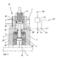
- In der Zeichnung ist ein Ausführungsbeispiel der Erfindung schematisch dargestellt. Es zeigen:
- Fig. 1
- eine Draufsicht auf eine am Schott befestigte Gesamtanordnung mit seinem Gehäuse mit einer Abdichtung sowie einer aufgenommenen Welle,
- Fig. 2
- eine Prinzipdarstellung der verstellbaren Dichtringe mit aufgenommer Welle und
- Fig. 3
- einen vergrößerten Schnitt durch eine Verstelleinheit mit zugeordneten Steuerelementen.
- Bei der dargestellten Anordnung ist ein zweiteiliges Gehäuse 1 an einer nicht näher dargestellten Schottwand eines Schiffes über Schrauben 2 befestigt. Das Gehäuse 1 besitzt eine Durchtrittsöffnung 3 zur Aufnahme einer Welle 4.
- Der Welle 4 sind im Gehäuse 1 einstellbare parallele Dichtringe 5, 6 aus einzelnen Segmenten 7 zugeordnet, die über Verzapfungen aus korrespondierenden Aufnahmen 8 und Führungselementen 9 in ihrem Durchmesser sternförmige zur Anlage und Abdichtung zur Welle 4 verstellbar sind. Dabei sind im Mantelbereich der Dichtringe 5, 6 Führungsnuten 10 zur Aufnahme eines ebenfalls segmentierten Druckringes 11 angeordnet, der über aufgenommene Ringfedern 12 als Zugfedern die Dichtringe 5, 6 zur Anlage an die Welle 4 presst.
- Zur Bildung eines Abstandes zwischen einem Durchmesser 13 der Welle 4 und dem Durchmesser 14 der Dichtringe 5, 6 ist jedem Segment 7 der parallel zugeordneten Dichtringe 5, 6 eine Verstellvorrichtung 15 zugeordnet, die radial zur Welle 4 auf die Segmente 7 der Dichtringe 5, 6 einwirkt. Hierbei ist eine zwischen den Dichtringen 5, 6 nach außen geführte Kolbenstange 16 angeordnet, die über ein Mitnehmerelement 17 im Bereich der Dichtringe 5, 6 in zugeordnete Aufnahmen 18 der Segmente 7 beiderseits zum Anheben eingreift, wobei die Kolbenstange 16 oberhalb der Dichtringe 5, 6 in einer Kolbenkammer 19 mit einem verstellbaren Kolben 20 verbunden ist. Oberhalb des Kolbens 20 ist eine Druckfeder 21 angeordnet, die im drucklosen Zustand der Kolbenkammer 19 den Kolben 20 in Richtung der Welle 4 führt. Bei einer Beaufschlagung der Kolbenkammer 19 mit einem Druckmedium wird hierbei die Welle 4 durch die Dichtringe 5, 6 nicht abdichtend beaufschlagt und ist im Abstand zur Welle angeordnet.
- Die Kolbenkammer 19 wird in diesem Ausführungsbeispiel über einen Anschluss 27 mit Druckluft beaufschlagt, wobei die Ansteuerung über eine Steuereinheit 22 erfolgt, die entsprechende Ventile 23, 24 steuert. Die Steuereinheit 22 wird dabei zusätzlich von einem Sensor 25 gesteuert, der bei Wasserdetektion die Druckluftzufuhr über das Ventil 24 unterbricht und über das Ventil 23 die Entlüftung der Kolbenkammer 19 herbeiführt. Zusätzlich wird bei einem Energieausfall ebenfalls über die Steuereinheit 22 und einen Energiewächter 26 die Entlüftung der Steuerkammer 19 herbeigeführt.
- Bei einer drucklosen Kolbenkammer 19 und einem damit verbundenen Störfall, werden durch Freigabe der einzelnen Segmente 7 über den Kolben 20 durch die Ringfedern 12 mit der Kolbenstange 16 und seinem Mitnehmerelement 17 die Dichtringe 5, 6 in eine Dichtposition auf die Welle 4 angelegt.
Claims (5)
- Schiff mit einer Schottabdichtung im Bereich von Wellendurchführungen durch einstellbare parallel zugeordnete Dichtringe aus korrespondierenden Segmenten, die jeweils über Verzapfungen verstellbar zugeordnet sind und zur sternförmigen Verstellung und Anlage auf der Welle durch einen einstellbaren segmentierten Druckring auf die Segmente der Dichtringe einwirken sowie über aufgenommene Ringfedern als Zugfedern die Dichtringe an die aufgenommene Welle pressen, wobei die Dichtringe und Druckringe in einem mit einer Schottwandung verbundenen Gehäuse angeordnet sind, dadurch gekennzeichnet, dass radial zur Welle (4) wirkende Verstelleinrichtungen (15) den einzelnen Segmenten (7) der Dichtringe im Gehäuse zugeordnet sind, wobei jede Verstelleinrichtung (15) durch eine zwischen den Dichtringen (5, 6) nach außen geführte Kolbenstange (16) aufweist, die am Ende ein Mitnehmerelement (17) trägt, das in zugeordnete Aufnahmen (18) der Segmente (7) der Dichtringe (5, 6) zum Anheben eingreift und oberhalb der Dichtringe (5, 6) eine Kolbenkammer (19) mit einem verstellbaren Kolben (20) am Ende der Kolbenstange (16) angeordnet ist und über ein steuerbares Druckmedium der Kolben (20) in eine Endstellung der Kolbenkammer (19) zum Anheben der Segmente (7) der Dichtringe (5, 6) im Abstand zur Welle (4) gegen die Kraft einer oberhalb des Kolbens (20) zugeordneten Druckfeder (21) und der Ringfedern (12) der Druckringe (11) einstellbar ist und im drucklosen Zustand der Kolben (20) über die Druckfeder (21) nach unten verstellbar ist und die Ringfedern (12) die Segmente (7) der Dichtringe (5, 6) über den Druckring (11) zur dichtenden Anlage an die Welle (4) anlegbar sind.
- Schiff nach Anspruch 1, dadurch gekennzeichnet, dass die Kolbenkammer (19) im Normalbetrieb durch das zugeführtes Druckmedium über eine Steuereinheit (22) zur Entkopplung der Dichtung durch Anheben der Dichtringe (5, 6) beaufschlagbar ist und bei auftretenden Störungen eine Aktivierung der Dichtringe (5, 6) zur Dichtung durch Druckentlastung der Kolbenkammer (19) selbsttätig einstellbar ist.
- Schiff nach Anspruch 1 oder 2, dadurch gekennzeichnet, dass das Druckmedium durch Druckluft gebildet ist.
- Schiff nach einem der Ansprüche 1 bis 3, dadurch gekennzeichnet, dass die Dichtringe (5, 6) zur Aufnahme korrespondierender Vorsprünge des zugeordneten Druckringes (11) Führungsnuten (10) aufweisen.
- Schiff nach einem der Ansprüche 1 bis 4, dadurch gekennzeichnet, dass jeder Dichtring (5, 6) aus sechs Segmenten (7) gebildet ist.
Applications Claiming Priority (1)
| Application Number | Priority Date | Filing Date | Title |
|---|---|---|---|
| DE201210004443 DE102012004443A1 (de) | 2012-02-29 | 2012-02-29 | Schiff mit einer Schottabdichtung im Bereich von Wellendurchführungen |
Publications (2)
| Publication Number | Publication Date |
|---|---|
| EP2634460A1 EP2634460A1 (de) | 2013-09-04 |
| EP2634460B1 true EP2634460B1 (de) | 2015-04-01 |
Family
ID=47721933
Family Applications (1)
| Application Number | Title | Priority Date | Filing Date |
|---|---|---|---|
| EP20130000507 Not-in-force EP2634460B1 (de) | 2012-02-29 | 2013-02-01 | Schiff mit einer Schottabdichtung im Bereich von Wellendurchführungen |
Country Status (8)
| Country | Link |
|---|---|
| US (1) | US9126668B2 (de) |
| EP (1) | EP2634460B1 (de) |
| JP (1) | JP6126868B2 (de) |
| KR (1) | KR20130099851A (de) |
| CN (1) | CN103291936B (de) |
| DE (1) | DE102012004443A1 (de) |
| DK (1) | DK2634460T3 (de) |
| RU (1) | RU2013108895A (de) |
Families Citing this family (8)
| Publication number | Priority date | Publication date | Assignee | Title |
|---|---|---|---|---|
| FR2997039B1 (fr) * | 2012-10-22 | 2015-01-16 | Dubuit Mach | Machine a imprimer par jets d'encre a lunette de calibrage |
| CN103825394A (zh) * | 2014-03-26 | 2014-05-28 | 湘潭电机股份有限公司 | 一种水下旋转密封结构 |
| JP6161208B2 (ja) * | 2014-10-30 | 2017-07-12 | 三菱日立パワーシステムズ株式会社 | クリアランス制御型シール構造 |
| CN104527933B (zh) * | 2014-12-10 | 2017-06-06 | 上海德瑞斯华海船用设备有限公司 | 可调式密封装置及包括其的舱室 |
| CN111799936A (zh) * | 2020-07-23 | 2020-10-20 | 佳木斯电机股份有限公司 | 一种用于电机轴的自调节动态密封装置 |
| CN115158626B (zh) * | 2022-06-30 | 2024-06-04 | 铁岭市机械橡胶密封件有限公司 | 一种舰艇隔舱用密封装置及方法 |
| CN116123286A (zh) * | 2023-03-31 | 2023-05-16 | 广东省科学院中乌焊接研究所 | 成型缸的活塞密封装置和增材制造设备 |
| CN118030847A (zh) * | 2024-01-31 | 2024-05-14 | 中国船舶集团有限公司第七一九研究所 | 一种浮式推进系统用隔舱密封装置 |
Family Cites Families (16)
| Publication number | Priority date | Publication date | Assignee | Title |
|---|---|---|---|---|
| US2071914A (en) * | 1935-12-07 | 1937-02-23 | B F Sturtevant Company Inc | Pressure compensation for packing |
| US2642942A (en) * | 1950-08-15 | 1953-06-23 | Charles B Reynolds | Drilling equipment and well pipe cleaner |
| US3948531A (en) * | 1975-04-24 | 1976-04-06 | Crane Packing Company | Bulkhead seal |
| CA1034977A (en) * | 1975-07-30 | 1978-07-18 | Edward J. Krisak | Bulkhead shaft seal |
| US4114058A (en) * | 1976-09-03 | 1978-09-12 | Westinghouse Electric Corp. | Seal arrangement for a discharge chamber for water cooled turbine generator rotor |
| DE3143866A1 (de) * | 1981-11-05 | 1983-05-11 | Howaldtswerke-Deutsche Werft Ag Hamburg Und Kiel, 2300 Kiel | Abdichtungsanordnung mit einem radialgleitring |
| US4449719A (en) * | 1982-04-01 | 1984-05-22 | John Crane Houdaille, Inc. | Emergency seal |
| NO841210L (no) * | 1983-04-21 | 1984-10-22 | Mitsubishi Heavy Ind Ltd | Tetningsanordning for aksel |
| JPS60127165U (ja) * | 1984-01-31 | 1985-08-27 | キ−パ−株式会社 | 船尾管緊急用シ−ル |
| JPH0665558B2 (ja) * | 1986-03-27 | 1994-08-24 | ロス インダストリ− ゲゼルシヤフト ミツト ベシユレンクテル ハフツング | 隔壁シ−ル |
| US4770387A (en) * | 1986-10-24 | 1988-09-13 | Nl Industries, Inc. | Variable ram seal for blowout preventers |
| US4927112A (en) | 1988-02-09 | 1990-05-22 | Doulbe-E Inc. | Blowout preventer |
| US6260817B1 (en) * | 1999-10-29 | 2001-07-17 | Stream-Flo Industries, Ltd. | Hydraulic blowout preventer assembly for production wellhead |
| CA2581508A1 (en) * | 2004-10-22 | 2006-04-27 | Burckhardt Compression Ag | Dry-running piston rod sealing arrangement, and method for sealing a piston rod using one such arrangement |
| DE102008037746A1 (de) * | 2008-08-14 | 2010-02-18 | Märkisches Werk GmbH | Ringdichtung |
| CN201330623Y (zh) * | 2008-12-15 | 2009-10-21 | 张焕元 | 汽轮发电机组轴承可调接触式密封装置 |
-
2012
- 2012-02-29 DE DE201210004443 patent/DE102012004443A1/de not_active Withdrawn
-
2013
- 2013-02-01 DK DK13000507.7T patent/DK2634460T3/en active
- 2013-02-01 EP EP20130000507 patent/EP2634460B1/de not_active Not-in-force
- 2013-02-26 KR KR20130020349A patent/KR20130099851A/ko not_active Withdrawn
- 2013-02-27 CN CN201310061363.1A patent/CN103291936B/zh not_active Expired - Fee Related
- 2013-02-27 RU RU2013108895/11A patent/RU2013108895A/ru not_active Application Discontinuation
- 2013-02-27 JP JP2013037015A patent/JP6126868B2/ja active Active
- 2013-02-28 US US13/780,155 patent/US9126668B2/en not_active Expired - Fee Related
Also Published As
| Publication number | Publication date |
|---|---|
| RU2013108895A (ru) | 2014-09-10 |
| DE102012004443A1 (de) | 2013-08-29 |
| US9126668B2 (en) | 2015-09-08 |
| CN103291936B (zh) | 2016-12-28 |
| KR20130099851A (ko) | 2013-09-06 |
| JP6126868B2 (ja) | 2017-05-10 |
| EP2634460A1 (de) | 2013-09-04 |
| CN103291936A (zh) | 2013-09-11 |
| US20130220196A1 (en) | 2013-08-29 |
| DK2634460T3 (en) | 2015-06-29 |
| JP2013181660A (ja) | 2013-09-12 |
Similar Documents
| Publication | Publication Date | Title |
|---|---|---|
| EP2634460A1 (de) | Schiff mit einer Schottabdichtung im Bereich von Wellendurchführungen | |
| WO2016113056A1 (de) | Verstellbare dämpfventileinrichtung | |
| EP3175138B1 (de) | Verstellbare dämpfventileinrichtung | |
| DE2005592A1 (de) | Absperrorgan mit Druckausgleichseinrichtung | |
| EP3470712B1 (de) | Hubventil und anordnung für ein hubventil | |
| DE2504616C2 (de) | Sicherheitsventil für fördernde Bohrlöcher | |
| AT509361B1 (de) | Spindellagerung | |
| DE102012014778A1 (de) | Ventiltrieb für eine Brennkraftmaschine | |
| EP1923586B1 (de) | Vorrichtung zum Klemmen von Wellen oder Ringen | |
| DE102008032031A1 (de) | Nockenwellenversteller | |
| EP2523063B2 (de) | Druckminderer | |
| EP2307751B1 (de) | An einem führungsholm einer scheibenbremse angeordneter faltenbalg | |
| DE3929094A1 (de) | Gebirgsschlagventil mit doppelkolben | |
| DE102009060755A1 (de) | Ventilanordnung und Werkzeugset | |
| EP3649367B1 (de) | Dämpfventil für einen schwingungsdämpfer | |
| DE60201895T2 (de) | Restdruckventil | |
| EP1703185B1 (de) | Coaxialventil | |
| DE102013206971B4 (de) | Hydraulikeinrichtung | |
| EP3514418B1 (de) | Einbauventil für einen ventilblock | |
| DE1807300U (de) | Schwingungsdaempfer. | |
| DE102012214713B4 (de) | Hydraulische Kolben-/Zylindereinheit | |
| DE102009058332A1 (de) | Axialkolbenmaschine | |
| DE102005023412B4 (de) | Einrichtung zur Lagerung einer ringförmigen Bremsscheibe auf einer Radnabe | |
| DE19842271C1 (de) | Hydraulisch angetriebener Drehantrieb mit Federrückstellung und Handbetätigung | |
| EP2711549B1 (de) | Steuervorrichtung für Pumpen bei Hochdruckreinigern |
Legal Events
| Date | Code | Title | Description |
|---|---|---|---|
| PUAI | Public reference made under article 153(3) epc to a published international application that has entered the european phase |
Free format text: ORIGINAL CODE: 0009012 |
|
| AK | Designated contracting states |
Kind code of ref document: A1 Designated state(s): AL AT BE BG CH CY CZ DE DK EE ES FI FR GB GR HR HU IE IS IT LI LT LU LV MC MK MT NL NO PL PT RO RS SE SI SK SM TR |
|
| AX | Request for extension of the european patent |
Extension state: BA ME |
|
| 17P | Request for examination filed |
Effective date: 20130816 |
|
| RAP1 | Party data changed (applicant data changed or rights of an application transferred) |
Owner name: SKF BLOHM + VOSS INDUSTRIES GMBH |
|
| GRAP | Despatch of communication of intention to grant a patent |
Free format text: ORIGINAL CODE: EPIDOSNIGR1 |
|
| INTG | Intention to grant announced |
Effective date: 20141031 |
|
| GRAS | Grant fee paid |
Free format text: ORIGINAL CODE: EPIDOSNIGR3 |
|
| GRAA | (expected) grant |
Free format text: ORIGINAL CODE: 0009210 |
|
| AK | Designated contracting states |
Kind code of ref document: B1 Designated state(s): AL AT BE BG CH CY CZ DE DK EE ES FI FR GB GR HR HU IE IS IT LI LT LU LV MC MK MT NL NO PL PT RO RS SE SI SK SM TR |
|
| REG | Reference to a national code |
Ref country code: GB Ref legal event code: FG4D Free format text: NOT ENGLISH |
|
| REG | Reference to a national code |
Ref country code: CH Ref legal event code: EP |
|
| REG | Reference to a national code |
Ref country code: IE Ref legal event code: FG4D Free format text: LANGUAGE OF EP DOCUMENT: GERMAN |
|
| REG | Reference to a national code |
Ref country code: DE Ref legal event code: R096 Ref document number: 502013000493 Country of ref document: DE Effective date: 20150507 |
|
| REG | Reference to a national code |
Ref country code: AT Ref legal event code: REF Ref document number: 719283 Country of ref document: AT Kind code of ref document: T Effective date: 20150515 |
|
| REG | Reference to a national code |
Ref country code: NL Ref legal event code: T3 |
|
| REG | Reference to a national code |
Ref country code: DK Ref legal event code: T3 Effective date: 20150626 |
|
| REG | Reference to a national code |
Ref country code: SE Ref legal event code: TRGR |
|
| REG | Reference to a national code |
Ref country code: NO Ref legal event code: T2 Effective date: 20150401 |
|
| REG | Reference to a national code |
Ref country code: LT Ref legal event code: MG4D |
|
| PG25 | Lapsed in a contracting state [announced via postgrant information from national office to epo] |
Ref country code: LT Free format text: LAPSE BECAUSE OF FAILURE TO SUBMIT A TRANSLATION OF THE DESCRIPTION OR TO PAY THE FEE WITHIN THE PRESCRIBED TIME-LIMIT Effective date: 20150401 Ref country code: PT Free format text: LAPSE BECAUSE OF FAILURE TO SUBMIT A TRANSLATION OF THE DESCRIPTION OR TO PAY THE FEE WITHIN THE PRESCRIBED TIME-LIMIT Effective date: 20150803 Ref country code: ES Free format text: LAPSE BECAUSE OF FAILURE TO SUBMIT A TRANSLATION OF THE DESCRIPTION OR TO PAY THE FEE WITHIN THE PRESCRIBED TIME-LIMIT Effective date: 20150401 Ref country code: CZ Free format text: LAPSE BECAUSE OF FAILURE TO SUBMIT A TRANSLATION OF THE DESCRIPTION OR TO PAY THE FEE WITHIN THE PRESCRIBED TIME-LIMIT Effective date: 20150401 Ref country code: HR Free format text: LAPSE BECAUSE OF FAILURE TO SUBMIT A TRANSLATION OF THE DESCRIPTION OR TO PAY THE FEE WITHIN THE PRESCRIBED TIME-LIMIT Effective date: 20150401 |
|
| PG25 | Lapsed in a contracting state [announced via postgrant information from national office to epo] |
Ref country code: RS Free format text: LAPSE BECAUSE OF FAILURE TO SUBMIT A TRANSLATION OF THE DESCRIPTION OR TO PAY THE FEE WITHIN THE PRESCRIBED TIME-LIMIT Effective date: 20150401 Ref country code: LV Free format text: LAPSE BECAUSE OF FAILURE TO SUBMIT A TRANSLATION OF THE DESCRIPTION OR TO PAY THE FEE WITHIN THE PRESCRIBED TIME-LIMIT Effective date: 20150401 Ref country code: IS Free format text: LAPSE BECAUSE OF FAILURE TO SUBMIT A TRANSLATION OF THE DESCRIPTION OR TO PAY THE FEE WITHIN THE PRESCRIBED TIME-LIMIT Effective date: 20150801 Ref country code: GR Free format text: LAPSE BECAUSE OF FAILURE TO SUBMIT A TRANSLATION OF THE DESCRIPTION OR TO PAY THE FEE WITHIN THE PRESCRIBED TIME-LIMIT Effective date: 20150702 |
|
| REG | Reference to a national code |
Ref country code: DE Ref legal event code: R097 Ref document number: 502013000493 Country of ref document: DE |
|
| PG25 | Lapsed in a contracting state [announced via postgrant information from national office to epo] |
Ref country code: EE Free format text: LAPSE BECAUSE OF FAILURE TO SUBMIT A TRANSLATION OF THE DESCRIPTION OR TO PAY THE FEE WITHIN THE PRESCRIBED TIME-LIMIT Effective date: 20150401 |
|
| PLBE | No opposition filed within time limit |
Free format text: ORIGINAL CODE: 0009261 |
|
| STAA | Information on the status of an ep patent application or granted ep patent |
Free format text: STATUS: NO OPPOSITION FILED WITHIN TIME LIMIT |
|
| REG | Reference to a national code |
Ref country code: FR Ref legal event code: PLFP Year of fee payment: 4 |
|
| PG25 | Lapsed in a contracting state [announced via postgrant information from national office to epo] |
Ref country code: RO Free format text: LAPSE BECAUSE OF NON-PAYMENT OF DUE FEES Effective date: 20150401 Ref country code: SK Free format text: LAPSE BECAUSE OF FAILURE TO SUBMIT A TRANSLATION OF THE DESCRIPTION OR TO PAY THE FEE WITHIN THE PRESCRIBED TIME-LIMIT Effective date: 20150401 Ref country code: PL Free format text: LAPSE BECAUSE OF FAILURE TO SUBMIT A TRANSLATION OF THE DESCRIPTION OR TO PAY THE FEE WITHIN THE PRESCRIBED TIME-LIMIT Effective date: 20150401 |
|
| 26N | No opposition filed |
Effective date: 20160105 |
|
| PGFP | Annual fee paid to national office [announced via postgrant information from national office to epo] |
Ref country code: DE Payment date: 20160218 Year of fee payment: 4 Ref country code: DK Payment date: 20160217 Year of fee payment: 4 Ref country code: IT Payment date: 20160229 Year of fee payment: 4 Ref country code: NO Payment date: 20160222 Year of fee payment: 4 |
|
| PG25 | Lapsed in a contracting state [announced via postgrant information from national office to epo] |
Ref country code: BE Free format text: LAPSE BECAUSE OF NON-PAYMENT OF DUE FEES Effective date: 20160229 Ref country code: SI Free format text: LAPSE BECAUSE OF FAILURE TO SUBMIT A TRANSLATION OF THE DESCRIPTION OR TO PAY THE FEE WITHIN THE PRESCRIBED TIME-LIMIT Effective date: 20150401 |
|
| PGFP | Annual fee paid to national office [announced via postgrant information from national office to epo] |
Ref country code: SE Payment date: 20160217 Year of fee payment: 4 Ref country code: FR Payment date: 20160218 Year of fee payment: 4 Ref country code: FI Payment date: 20160211 Year of fee payment: 4 Ref country code: NL Payment date: 20160217 Year of fee payment: 4 |
|
| PG25 | Lapsed in a contracting state [announced via postgrant information from national office to epo] |
Ref country code: MC Free format text: LAPSE BECAUSE OF FAILURE TO SUBMIT A TRANSLATION OF THE DESCRIPTION OR TO PAY THE FEE WITHIN THE PRESCRIBED TIME-LIMIT Effective date: 20150401 Ref country code: LU Free format text: LAPSE BECAUSE OF FAILURE TO SUBMIT A TRANSLATION OF THE DESCRIPTION OR TO PAY THE FEE WITHIN THE PRESCRIBED TIME-LIMIT Effective date: 20160201 |
|
| REG | Reference to a national code |
Ref country code: CH Ref legal event code: PL |
|
| PG25 | Lapsed in a contracting state [announced via postgrant information from national office to epo] |
Ref country code: LI Free format text: LAPSE BECAUSE OF NON-PAYMENT OF DUE FEES Effective date: 20160229 Ref country code: CH Free format text: LAPSE BECAUSE OF NON-PAYMENT OF DUE FEES Effective date: 20160229 |
|
| REG | Reference to a national code |
Ref country code: IE Ref legal event code: MM4A |
|
| PG25 | Lapsed in a contracting state [announced via postgrant information from national office to epo] |
Ref country code: IE Free format text: LAPSE BECAUSE OF NON-PAYMENT OF DUE FEES Effective date: 20160201 |
|
| PG25 | Lapsed in a contracting state [announced via postgrant information from national office to epo] |
Ref country code: MT Free format text: LAPSE BECAUSE OF FAILURE TO SUBMIT A TRANSLATION OF THE DESCRIPTION OR TO PAY THE FEE WITHIN THE PRESCRIBED TIME-LIMIT Effective date: 20150401 |
|
| REG | Reference to a national code |
Ref country code: DE Ref legal event code: R119 Ref document number: 502013000493 Country of ref document: DE |
|
| REG | Reference to a national code |
Ref country code: DK Ref legal event code: EBP Effective date: 20170228 |
|
| REG | Reference to a national code |
Ref country code: NO Ref legal event code: MMEP |
|
| REG | Reference to a national code |
Ref country code: SE Ref legal event code: EUG |
|
| REG | Reference to a national code |
Ref country code: NL Ref legal event code: MM Effective date: 20170301 |
|
| GBPC | Gb: european patent ceased through non-payment of renewal fee |
Effective date: 20170201 |
|
| PG25 | Lapsed in a contracting state [announced via postgrant information from national office to epo] |
Ref country code: FI Free format text: LAPSE BECAUSE OF NON-PAYMENT OF DUE FEES Effective date: 20170201 Ref country code: NO Free format text: LAPSE BECAUSE OF NON-PAYMENT OF DUE FEES Effective date: 20170228 |
|
| PG25 | Lapsed in a contracting state [announced via postgrant information from national office to epo] |
Ref country code: NL Free format text: LAPSE BECAUSE OF NON-PAYMENT OF DUE FEES Effective date: 20170301 Ref country code: SE Free format text: LAPSE BECAUSE OF NON-PAYMENT OF DUE FEES Effective date: 20170202 |
|
| REG | Reference to a national code |
Ref country code: FR Ref legal event code: ST Effective date: 20171031 |
|
| PG25 | Lapsed in a contracting state [announced via postgrant information from national office to epo] |
Ref country code: DE Free format text: LAPSE BECAUSE OF NON-PAYMENT OF DUE FEES Effective date: 20170901 Ref country code: DK Free format text: LAPSE BECAUSE OF NON-PAYMENT OF DUE FEES Effective date: 20170228 Ref country code: FR Free format text: LAPSE BECAUSE OF NON-PAYMENT OF DUE FEES Effective date: 20170228 |
|
| PG25 | Lapsed in a contracting state [announced via postgrant information from national office to epo] |
Ref country code: GB Free format text: LAPSE BECAUSE OF NON-PAYMENT OF DUE FEES Effective date: 20170201 Ref country code: IT Free format text: LAPSE BECAUSE OF NON-PAYMENT OF DUE FEES Effective date: 20170201 |
|
| PG25 | Lapsed in a contracting state [announced via postgrant information from national office to epo] |
Ref country code: HU Free format text: LAPSE BECAUSE OF FAILURE TO SUBMIT A TRANSLATION OF THE DESCRIPTION OR TO PAY THE FEE WITHIN THE PRESCRIBED TIME-LIMIT; INVALID AB INITIO Effective date: 20130201 Ref country code: CY Free format text: LAPSE BECAUSE OF FAILURE TO SUBMIT A TRANSLATION OF THE DESCRIPTION OR TO PAY THE FEE WITHIN THE PRESCRIBED TIME-LIMIT Effective date: 20150401 Ref country code: SM Free format text: LAPSE BECAUSE OF FAILURE TO SUBMIT A TRANSLATION OF THE DESCRIPTION OR TO PAY THE FEE WITHIN THE PRESCRIBED TIME-LIMIT Effective date: 20150401 |
|
| PG25 | Lapsed in a contracting state [announced via postgrant information from national office to epo] |
Ref country code: MK Free format text: LAPSE BECAUSE OF FAILURE TO SUBMIT A TRANSLATION OF THE DESCRIPTION OR TO PAY THE FEE WITHIN THE PRESCRIBED TIME-LIMIT Effective date: 20150401 Ref country code: TR Free format text: LAPSE BECAUSE OF FAILURE TO SUBMIT A TRANSLATION OF THE DESCRIPTION OR TO PAY THE FEE WITHIN THE PRESCRIBED TIME-LIMIT Effective date: 20150401 |
|
| PG25 | Lapsed in a contracting state [announced via postgrant information from national office to epo] |
Ref country code: BG Free format text: LAPSE BECAUSE OF FAILURE TO SUBMIT A TRANSLATION OF THE DESCRIPTION OR TO PAY THE FEE WITHIN THE PRESCRIBED TIME-LIMIT Effective date: 20150401 |
|
| PG25 | Lapsed in a contracting state [announced via postgrant information from national office to epo] |
Ref country code: AL Free format text: LAPSE BECAUSE OF FAILURE TO SUBMIT A TRANSLATION OF THE DESCRIPTION OR TO PAY THE FEE WITHIN THE PRESCRIBED TIME-LIMIT Effective date: 20150401 |
|
| REG | Reference to a national code |
Ref country code: AT Ref legal event code: MM01 Ref document number: 719283 Country of ref document: AT Kind code of ref document: T Effective date: 20180201 |
|
| PG25 | Lapsed in a contracting state [announced via postgrant information from national office to epo] |
Ref country code: AT Free format text: LAPSE BECAUSE OF NON-PAYMENT OF DUE FEES Effective date: 20180201 |