EP2634352A2 - Dachfensterblendenvorrichtung mit gestapelten Blendenplatten - Google Patents
Dachfensterblendenvorrichtung mit gestapelten Blendenplatten Download PDFInfo
- Publication number
- EP2634352A2 EP2634352A2 EP13157129.1A EP13157129A EP2634352A2 EP 2634352 A2 EP2634352 A2 EP 2634352A2 EP 13157129 A EP13157129 A EP 13157129A EP 2634352 A2 EP2634352 A2 EP 2634352A2
- Authority
- EP
- European Patent Office
- Prior art keywords
- shutter plates
- shutter
- screening
- plates
- roof window
- Prior art date
- Legal status (The legal status is an assumption and is not a legal conclusion. Google has not performed a legal analysis and makes no representation as to the accuracy of the status listed.)
- Withdrawn
Links
- 238000012216 screening Methods 0.000 claims abstract description 142
- 230000007246 mechanism Effects 0.000 claims abstract description 27
- 230000008878 coupling Effects 0.000 description 10
- 238000010168 coupling process Methods 0.000 description 10
- 238000005859 coupling reaction Methods 0.000 description 10
- 238000007789 sealing Methods 0.000 description 9
- 238000010276 construction Methods 0.000 description 7
- 239000000463 material Substances 0.000 description 4
- 230000008901 benefit Effects 0.000 description 3
- 238000004891 communication Methods 0.000 description 3
- 238000009434 installation Methods 0.000 description 3
- 238000000034 method Methods 0.000 description 3
- 238000004040 coloring Methods 0.000 description 2
- 230000000994 depressogenic effect Effects 0.000 description 2
- 238000011161 development Methods 0.000 description 2
- 238000003780 insertion Methods 0.000 description 2
- 230000037431 insertion Effects 0.000 description 2
- 230000007704 transition Effects 0.000 description 2
- XLYOFNOQVPJJNP-UHFFFAOYSA-N water Substances O XLYOFNOQVPJJNP-UHFFFAOYSA-N 0.000 description 2
- 230000003028 elevating effect Effects 0.000 description 1
- 238000001125 extrusion Methods 0.000 description 1
- 230000005484 gravity Effects 0.000 description 1
- 230000035515 penetration Effects 0.000 description 1
- 230000009467 reduction Effects 0.000 description 1
Images






Classifications
-
- E—FIXED CONSTRUCTIONS
- E06—DOORS, WINDOWS, SHUTTERS, OR ROLLER BLINDS IN GENERAL; LADDERS
- E06B—FIXED OR MOVABLE CLOSURES FOR OPENINGS IN BUILDINGS, VEHICLES, FENCES OR LIKE ENCLOSURES IN GENERAL, e.g. DOORS, WINDOWS, BLINDS, GATES
- E06B9/00—Screening or protective devices for wall or similar openings, with or without operating or securing mechanisms; Closures of similar construction
- E06B9/02—Shutters, movable grilles, or other safety closing devices, e.g. against burglary
- E06B9/06—Shutters, movable grilles, or other safety closing devices, e.g. against burglary collapsible or foldable, e.g. of the bellows or lazy-tongs type
- E06B9/0607—Shutters, movable grilles, or other safety closing devices, e.g. against burglary collapsible or foldable, e.g. of the bellows or lazy-tongs type comprising a plurality of similar rigid closing elements movable to a storage position
- E06B9/0646—Shutters, movable grilles, or other safety closing devices, e.g. against burglary collapsible or foldable, e.g. of the bellows or lazy-tongs type comprising a plurality of similar rigid closing elements movable to a storage position characterised by the relative arrangement of the closing elements in the stored position
- E06B9/0676—Shutters, movable grilles, or other safety closing devices, e.g. against burglary collapsible or foldable, e.g. of the bellows or lazy-tongs type comprising a plurality of similar rigid closing elements movable to a storage position characterised by the relative arrangement of the closing elements in the stored position stored in a stacked configuration
-
- E—FIXED CONSTRUCTIONS
- E04—BUILDING
- E04D—ROOF COVERINGS; SKY-LIGHTS; GUTTERS; ROOF-WORKING TOOLS
- E04D13/00—Special arrangements or devices in connection with roof coverings; Protection against birds; Roof drainage ; Sky-lights
- E04D13/03—Sky-lights; Domes; Ventilating sky-lights
- E04D13/033—Sky-lights; Domes; Ventilating sky-lights provided with means for controlling the light-transmission or the heat-reflection, (e.g. shields, reflectors, cleaning devices)
-
- E—FIXED CONSTRUCTIONS
- E06—DOORS, WINDOWS, SHUTTERS, OR ROLLER BLINDS IN GENERAL; LADDERS
- E06B—FIXED OR MOVABLE CLOSURES FOR OPENINGS IN BUILDINGS, VEHICLES, FENCES OR LIKE ENCLOSURES IN GENERAL, e.g. DOORS, WINDOWS, BLINDS, GATES
- E06B9/00—Screening or protective devices for wall or similar openings, with or without operating or securing mechanisms; Closures of similar construction
- E06B9/02—Shutters, movable grilles, or other safety closing devices, e.g. against burglary
- E06B9/06—Shutters, movable grilles, or other safety closing devices, e.g. against burglary collapsible or foldable, e.g. of the bellows or lazy-tongs type
- E06B9/0607—Shutters, movable grilles, or other safety closing devices, e.g. against burglary collapsible or foldable, e.g. of the bellows or lazy-tongs type comprising a plurality of similar rigid closing elements movable to a storage position
- E06B9/0615—Shutters, movable grilles, or other safety closing devices, e.g. against burglary collapsible or foldable, e.g. of the bellows or lazy-tongs type comprising a plurality of similar rigid closing elements movable to a storage position characterised by the closing elements
- E06B9/0638—Slats or panels
Definitions
- the present invention relates to a roof window shutter device for screening an opening, in particular the light-admitting area of a window mounted in an inclined roof surface, comprising a plurality of mutually articulated shutter plates, a drive mechanism for movement of the shutter plates between a storage position in a top casing, in which the shutter plates are stacked substantially in parallel with each other, and a screening position with the shutter plates positioned in front of the opening and in extension of each other, which screening position is defined by a pair of guide rails extending from the top casing and guiding opposing side portions of the shutter plates.
- DE 29 47 501 discloses a roof window shutter device comprising a plurality of articulated shutter plates, and a drive mechanism for moving the shutter plates between a screening position where the shutter plates are positioned in front of the window and a storage position where the shutter plates are stacked in a top casing. In the storage position the shutter plates are stacked in a zig-zag pattern so that a front face of a shutter plate faces a front face of an adjacent shutter plate and a rear face of a shutter plate faces a rear face of an adjacent shutter plate, respectively.
- a shutter device for screening a façade aperture such as garages and shop windows.
- the shutter device comprises a top casing to be positioned inside the aperture so as to store shutter plates when not used to screen the aperture in a screening position.
- the shutter plates are articulated by connecting members, which respectively are pivotally and slidably connected to adjacent shutter plates so as to allow the shutter plates to be stacked when moved by a drive mechanism from the screening position to a storage position inside the top casing.
- a façade shutter with a similar principle is known from WO 03/ 060274.
- WO 98/59144 and WO 98/27306 it is known to provide a shutter device for screening a façade aperture, wherein side portions of shutter plates are guided in tracks extending along the aperture and into a top casing for stacking the shutter plates.
- the shutter plates are stacked in the top casing by means of a lift cable and a spring-loaded winder.
- the present invention is characterized in that the top casing comprises opposing first guide tracks and opposing second guide tracks wherein first slide members and second slide members of the shutter plates are guided when the shutter plates are moved between the storage position and the screening position, that adjacent shutter plates are interconnected by connecting members with a first connecting portion pivotally connected and a second connecting portion slidably and pivotally connected to adjacent side portions of the adjacent shutter plates, and that the opposing side portions of the shutter plates are provided with a guide guiding the second connecting portion of the connecting members during movement of the shutter plates between the storage position and the screening position.
- the guide tracks ensure that the shutter plates are guided to the intended position.
- the flexible link between the shutter plates and the guide tracks makes it possible to guide the shutter plates to a storage position determined by the shape of the guide tracks, e.g. by tilting and elevating the shutter plates with respect to the screening plane without increasing the overall height of the top casing. Due to gravity forces a correct guidance of the shutter plates is especially important to ensure stable operation of the shutter plates of a roof window shutter device as the forces exerted on the shutter plates during movement between the screening position and the storage position or vice versa otherwise may result in tangled or stuck shutter plates.
- the invention brings the advantage that stable operation of the shutter plates may be achieved even with relatively large shutter plates, i.e. the number of shutter plates may be reduced to for instance five or less. Hence less parts to assemble and less movable parts critical to obtain a stable operation.
- connection members comprises the second slide members. This provides for an even more simple construction as to the number of parts and assembly, and a slide member may more easily be replaced.
- the second slide members may be provided separately from the connection members, preferably connected to the shutter plates.
- the second slide members and the first connecting portions of the connecting members are plane-parallel. This configuration has shown to be especially practical in order to provide a slim configuration of the top casing.
- the opposing side portions define a length of the shutter plates extending between side portions extending in a width direction of the shutter plates, wherein the first slide members of the shutter plates are positioned between the guides and a side portion.
- the guides of the side portions extend about 50 %, preferably about 75 %, and more preferably about 90 % of the length defined by the side portions.
- the guide tracks in the top casing are adapted to angle the shutter plates with respect to the screening position when moved to the storage position.
- the shutter plates When the shutter plates are positioned in the screening position they preferably abut, and ice on the abutting surfaces of the shutter plates may cause the shutter plates to get stuck together.
- the shutter plates When the shutter plates are angled with respect to the screening plane when they are moved into the top casing towards the storage position, the ice may be broken and the shutter plates released from each other.
- this is achieved when the first opposing guide tracks are provided with a bow so as to angle the shutter plates with respect to the screening position during movement of the shutter plates from the screening position to the storage position.
- the side portions of the shutter plates are provided with toothed racks to engage with a pinion of the drive mechanism.
- a tooth of the toothed rack is configured to allow the drive mechanism to engage between two adjacent shutter plates when one of the shutter plates is angled with respect to the screening position and the other is still in the screening position.
- the shutter plates are stacked substantially in parallel with a screening plane defined by the shutter plates in the screening position.
- the connecting members are positioned at an end of the guide facing towards a screening plane defined by the shutter plates in the screening position.
- the pivot connection of the connecting member ensure that the shutter plates are lifted from the storage position when the shutter plates are moved from the storage position towards the screening position. This prevents the shutter plates from being stuck in the guide tracks when the shutter plates are lifted from the storage position to be guided to the screening position.
- the shutter plates are stacked substantially perpendicular to a screening plane defined by the shutter plates in the screening position. This has shown to be especially advantageous when the slide pins extend from the side portion of the shutter plates.
- the roof window shutter device comprising a lower shutter plate, which in the screening position is tilted with respect to the other shutter plates defining a screening plane. This provides for a better screening of the entire opening and the window in the screening position, and allows more light to enter the opening when the shutter plates are in the storage position.
- the guide rails and the top casing when mounted on a roof window by means of a mounting bracket fixed in relation to the roof, are rotatable about an axis of rotation parallel with a screening plane defined by the shutter plates in the screening position.
- the guide rails ensure a precise movement of the shutter plates to the screening position, and if the guide rails are mounted on a stationary window frame or the roof, a movable sash may, with the shutter plates in the screening position, be turned with respect to the frame so as to lift and rotate the guide rails and the top casing about the axis of rotation.
- Fig. 1 depicts a roof window shutter device 1 according to the invention which is mounted on a roof window 2 of the make VELUX® GGL with a sash 3 movable with respect to a frame 4 on which the roof window shutter device 1 is mounted.
- the roof window shutter device 1 comprises a flashing 5 extending along opposing side members 6, 7 of the frame 4 and a top member perpendicular to the side members 6, 7.
- the roof window shutter device 1 comprises a top casing 8 which, in a condition of use, is positioned at the top member of the frame 4 so that the flashing extends along a bottom of the top casing 8.
- the top casing 8 is pivotally fixed to the flashing by means of a mounting bracket 9, which again, in a condition of use, is fixed to a rafter of a roof wherein the window is installed.
- the roof window shutter device according to an embodiment of the invention shown in Fig. 1 is depicted in a storage position wherein shutter plates 11 for screening an opening 10 of the roof window 2 are positioned inside the top casing 8.
- the shutter plates 11 are shown in a screening position in Fig. 2 .
- the shutter plates 11 are stacked inside the top casing 8 from which a pair of guide rails 12 extends along the side members 6, 7 of the frame 4.
- the top casing 8 comprises an aperture 16 through which the shutter plates 11 are guided when moved between the storage position shown in Fig.
- the guide rails 12 are connected to and extend from the top casing 8, which in a mounted condition is pivotally fixed to the roof so that the sash may be turned with respect to the frame even when the shutter plates 11 are in the screening position as depicted in Fig. 2 , because the sash 3 will encounter the shutter plates 11 and lift the shutter plates 11, and the guide rails 12 and the top casing 8 will pivot about the pivotal connection to the roof.
- the guide rails 12 may be positioned a short distance from the top casing 8.
- left-hand and “right-hand” refer to the orientation shown in for instance Fig. 1 and are utilized for reasons of convenience only.
- the terms “upper” and “lower” refer to the orientation of an element with respect to the top casing, “upper” being a portion of an element intended to face towards the top casing, “lower” being a portion of an element intended to face away from the top casing in for instance in Fig. 2 .
- the terms “front” and “rear” are utilized to denote the sides of the screening arrangement, “rear” being the side intended to face towards the roof of the building, and “front” the outwards facing side.
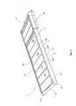
- Fig. 2 shows the roof window shutter device 1 taken alone without the window 2 and the flashing 5 shown in Fig. 1 .
- the shutter plates 11 are guided by the guide rails 12 and define a screening plane.
- the roof window shutter device 1 comprises four shutter plates 11 defining the screening plane, and a lower shutter plate 11a having a reduced size compared to the other shutter plates 11.
- the lower shutter plate 11a When the lower shutter plate 11a is moved to a distal end of the guide rails 12, which is closed off by bottom pieces 14, it is angled with respect to the screening plane and screen the opening between the guide rails 12.
- the shutter plates 11 In the screening position as shown in Fig. 2 , the shutter plates 11 extend in a width direction between the guide rails.
- the shutter plates have parallel side portions 15 extending perpendicularly between the upper 100 and lower 110 lateral side portions.
- the height of the shutter plates defined by the parallel opposing side portions 15 are preferred to be within 100 to 700 mm, more preferably with in 200 to 600 mm and even more preferably within 300 to 600 mm. In a preferred embodiment the height of the shutter plates are 400 mm. Such embodiment is depicted in Fig.
- the width of the shutter plates and/or the number of shutter plates 11 is adjusted.
- the shutter plates are connected at their side portions 15 so that when positioned in the screening position they may be moved to the storage position, where the shutter plates 11 are stacked in the top casing 8, by pulling the uppermost shutter plate 11, which has just entered the interior of the top casing 8. In the same manner the shutter plates 11 may be pulled from the storage position towards the aperture of the top casing 8 and thus eventually pushed towards the screening position.
- the lower shutter plate 11a is angled with respect to the other shutter plates 11 and closes off the opening between the two guide rails 12. In the screening position one of the shutter plates is not fully released from the aperture 16 of the top casing 8 from which the guide rails 12 extend.
- the aperture 16 is formed in a side wall 24 for abutting the upper member of the frame 4. Adjacent to the aperture 16 a drive mechanism 17 is provided inside the top casing 8. The drive mechanism 17 interacts with the shutter plates 11 so as to provide movement between the storage position and the screening position.
- the guide tracks 19, 20 in each side of the top casing 8 comprises first and second guide tracks 19, 20, which extend from the aperture 16 towards a bottom plate 22 of the top casing.
- the guide rails 12 may comprise guide tracks extending in different planes so that the first and second guide tracks 19, 20 of the top casing 8 may have corresponding guide tracks in the guide rails.
- the slide members 27, 28 of the shutter plates are in one embodiment positioned in different planes, e.g. close to the front and rear side surfaces 120, 130 of the shutter plates, respectively.
- the drive mechanism 17 will eventually begin to interact with the following adjacent shutter plate so that the shutter plates are pushed by a following shutter plate until the storage position has been reached.
- operation of the drive mechanism may be reversed so as to move the shutter plates 11 in an opposite direction.
- the drive mechanism 17 comprises a toothed wheel 25, which interacts with toothed racks 26 of the side portions 15.
- the rear side of the side portions 15 abut the guide rails 12 in the screening position, i.e. the toothed racks 26 abut the guide rails 12 and slide on the guide rails 12 during movement of the shutter plates.
- the drive mechanism 17 is an electric tubular actuator.
- the drive mechanism 17 may also be manually operated such as by turning or pulling an operating handle.
- the guide rails 12 may be connected to the top casing 8 and extend from the aperture 16 and they may be positioned adjacent to the aperture 16 to receive the shutter plates 11 when released from the aperture.
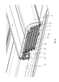
- Fig. 4 one of the opposing side walls 18 of the top casing 8 has been removed and the shutter plates 11 are shown in the storage position where the shutter plates 11 are guided to by the guide tracks 19, 20.
- the shutter plates 11 may be guided by only one guide track 20 in each side of the top casing 8.
- the shutter plates 11 are stacked in parallel with each other, and in the embodiment shown also in parallel with the screening plane defined by the shutter plates in the screening position and with the front surface 120 facing a rear surface 130 of a neighbouring shutter plate. And the shutter plate positioned in the bottom of the stack of shutter plates is positioned below the screening plane.
- Fig. 3 and in further detail in Fig.
- the opposing side walls of the top casing comprise guide tracks 19, 20 wherein the opposing side portions 15 of the shutter plates 11 are guided.
- the guidance of the side portions 15 in the guide tracks 19, 20 may be achieved by providing the side portions 15 with slide members in the form of slide pins 27, 28, which are guided in the guide tracks 19, 20.
- the shutter plates 11 are connected by connecting members 29, i.e. an elongate swivel arm, which at each end is at least pivotally connected to the side portions of two neighbouring shutter plates 11.
- a slide pin 28 may be provided on the connecting member 29. A portion of such connecting member 29 is both pivotally and slidably connected to a shutter plate.
- a second connecting portion 31b may slide and pivot when the shutter plates 11 are moved between the storage position and the screening position.
- a first connecting portion 31a of such connecting member 29 is pivotally connected to a neighboring shutter plate 11 by means of a pin located in a bore next to an elongate guide 30 present on said neighboring shutter plate.
- the connection at one end may deviate slightly from being only pivotal. For instance a short track of a length of for instance 0.5 or 1 cm is conceivable as well. As seen in for instance Fig. 5 in conjunction with Fig.
- the slide pin 27 has an elongated, slightly flattened shape in order to contribute to a reduction in the height or thickness of the shutter body.
- the shape provides the possibility of obtaining proper sliding engagement, while at the same time allowing the slide pin 27 to be adapted to the front surface 120 of the shutter plates 11.
- the connecting members 29 are positioned at the lower lateral side sections of the shutter plates.
- the second connecting portion 31b is slided along the guide 30 from a position at the lower lateral side portion 110 of the shutter plate 11 towards the upper lateral side portion 100 of the shutter plate 11 until the second connecting portion 31b reaches the end of the guide 30 so that only a pivotal movement of the connecting member 29 is possible as long the drive mechanism 17 moves the shutter plates towards the screening position.
- the second connecting portion 31b has reached the end of the guide 30, the next shutter plate in the stack is pulled towards the drive mechanism 17 and the aperture 16, and the same sliding movement as described above will start for the next pair of connecting members 29.
- the shutter plates are pulled from the storage position towards the screening position they will eventually engage with the drive mechanism 17.
- shutter plates 11 When the shutter plates 11 lose engagement with the drive mechanism 17 they are pushed further towards the screening position by the following shutter plate, which engage with the drive mechanism 17 and is moved towards the screening position. This may continue until all shutter plates are positioned in their respective screening positions as described above in relation to Fig. 3 .
- the pivotal connection between the side portions 15 of the shutter plates ensure that the shutter plates may be moved from the stacked storage position where the font surface 120 and rear surface 130 of neighboring shutter plates face each other, to a the screening position wherein the upper 100 and lower lateral 110 side sections of neighboring shutter plates face each other.
- the guide 30 may be provided on the rear side 130 of the side portion 15 and still extend between the upper 100 and lower 110 lateral side sections of shutter plates 11. This will also allow the guide 30 to be protected in the screening position as this portion of the rear surface 130, during movement to and from the in the screening position, will slide on a slide surface 50 of the guide rails 12.
- Fig. 6 shows a side view of the top casing 8 taken alone without the guide rails and the shutter plates.
- the shutter plates are guided between the screening position and the storage position.
- a first slide pin 27 positioned closest to the upper lateral side portion 100 is guided into an upper guide track 20, which for a first portion 32 extends in parallel with the screening plane until a second portion 33 is reached.
- the second portion 33 is configured, e.g. with a bend with away from the first portion 32 towards a bottom plate 40 of the top casing 8. This allows a shutter plate to be slightly angled with respect to the screening plane when moved from the screening position towards the storage position.
- a neighboring shutter plate connected to a shutter plate which has been angled is still in the screening plane and the angle may serve to break ice between the upper 100 and lower 110 lateral side portion of neighboring shutter plates 11 abutting in the screening position. It is preferred that the shutter plates are tilted between 1 and 10 degrees, preferably about 3 degrees with respect to the screening plane.
- the second portion 33 of the upper guide track 20 extends into a third portion 34 extending substantially in parallel with the first portion 32, and where the slide pin 27 of a shutter plate rest when a shutter plate 11 is angled. From the third portion 34 the guide track 20 bend towards the bottom plate 40 of the top casing 40, preferably in parallel with a lower guide track 19, which guides the slide pin 28 of the shutter plates.
- the length of the connecting members 25 and the elongate groove are configured such that an interspace is provided between the upper and lower lateral side sections of neighboring shutter plates, when the shutter plates are moved from the screening position towards the storage position.
- this is obtained with a length between the first connecting portion 31a and the second connecting portion 31b of the connecting member 29, which allows a shutter plate to swivel about an axis of a pivot pin of a neighboring shutter plate when the shutter plates are moved to the stacked position below the screening plate.
- this configuration serves to break ice between abutting upper 100 and lower 110 lateral side portions of neighboring shutter plates, but also makes it possible to provide an intermediate screening position with a light admitting interspace extending between the side portions 15 of the shutter plates between upper and lower lateral side sections of neighboring shutter plates. Furthermore, such configuration may serve to reduce the height of the top casing required for stacking the shutter plates in the storage position.
- a first and last tooth of the toothed racks 26, i.e. the teeth that will be adjacent to each other in the screening position, are reduced in size compared to the remaining teeth of the toothed rack 26.
- the space between these teeth when positioned next to each other in the screening position are reduced in size compared to the space between the remaining teeth of the toothed rack 26.
- the first guide track 20 and the length of the shutter plates are configured so that when a shutter plate it tilted with respect to the screening plane as described above, a tooth of the toothed wheel 25 is forced into the reduced space between the shutter plates. Thereby even more ice between two shutter plates may be broken and the shutter plates may be separated so the lateral side sections are free of each other to swivel towards the screening position.
- Fig. 7 is a perspective view of roof window shutter device 1 mounted on a window 2 taken from a different angle than Fig. 1 .
- the top casing 8 is pivotally connected to the flashing 5. This may the provision of one or more coupling arms pivotally connected to one or more mounting brackets 9 on the flashing 5.
- each side of the top casing 8 comprises a coupling arm 50 (cf. Figs. 3 and 6 ) for mounting in a mounting bracket 9, which for the explanation of the invention is only mounted in one side of the flashing.
- the flashing 5 is preferably U-shaped with legs for extending along the opposing side members of the window frame, and a plate section extending along the top member of the frame 2 and below the top casing 8.
- Fig. 8 shows a flashing 5 according to the invention taken from the same angle as Fig. 7 , but with the window and the roof window shutter device 1, and a side portion of the flashing removed.
- the mounting bracket 9 is still removed as in Fig. 7 .
- the flashing comprises a opening 61 with an upright standing wall extending on the front side of the flashing when the flashing is installed in connection with a roof window.
- a screw hole 62 for fixing the mounting bracket 9 to the flashing 5 from the rear side facing the roof in a condition of use may be provided next to the opening 61.
- the flashing 5 may be provided with indications such as smaller holes, graphical marking or different coloring to indicate the correct position of the mounting bracket on the flashing 5.
- Fig. 9 is a cross sectional view through the mounting bracket 9 in a preferred embodiment when mounted on the flashing 5 and installed on a roof.
- the mounting bracket 9 is fixed to the flashing 5 by means of a screw 63, the head of which is hidden in a dimple in the rear side of the flashing 5, i.e. in a knob protruding in the front side of the flashing 5.
- the upright standing wall 64 extending on the front surface of the flashing 5 is provided with a sealing ring 65 so as to prevent water from entering the roof through the opening 61.
- a console 66 with a bore 67 in communication with a corresponding bore in the mounting bracket 9 positioned at position 60 is provided inside the upright standing wall 64 .
- the console 66 can be dispensed with but it is used in a preferred embodiment during installation.
- the bore 67 which is accessed from the top of the mounting bracket 9 mounted at position 60 is used for fixing the mounting bracket 9 and the flashing to a beam of the roof by use of a fastening member such as a screw inserted though the bore and fixed in the roof, in particular in a carrying part of the roof structure, such as a rafter.
- the flashing 5 and mounting bracket 9 is preferably mounted in connection with a roof window in the following way.
- a flashing template of a light foldable material such as plastic or paper is positioned at the roof window 2 as is intended with the flashing 5.
- Markings in the flashing template indicate the position 60 where the mounting brackets 9 are to be positioned when the flashing 5 is positioned.
- the marking in the flashing template may be openings or graphical indications or different coloring.
- the flashing template is preferably shaped as the flashing 5 or at least as the plate section of the flashing extending alongside the top member of the window frame in a condition of use.
- the console 66 for receiving the mounting bracket 9 at position 60 is then mounted on a beam on the roof at a position indicated by the flashing template.
- the console is fixed to the roof by fastening members inserted through further bores 68 in the console.
- the console may be without any bores if made of a material that may be penetrated by a fastening member.
- the flashing and the mounting bracket which also simply may be penetrated by a fastening member during installation in relation to a roof window. If required the beam of the roof may be adjusted to ensure than the flashing 5 and the mounting bracket 9 are securely fixed to the roof, i.e.
- an auxiliary beam element may be added to the roof construction to provide a suitable fixing point for the fastening member fixing the flashing and the mounting bracket 9 to the roof. Then the top casing 8 is pivotally connected to the mounting bracket about an axis of rotation parallel with the longitudinal direction of the shutter plates between the guide rails 12.
- Fig. 10 shows a perspective view of the mounting bracket 9. It comprises a base 70 with two wall portions 71 between which the coupling arm 50 of the top casing 8 is positioned during installation of the roof window shutter device 1.
- the coupling arm 50 is pivotally connected to the mounting bracket by means of a pin inserted in a through-going bore of the wall portions 71 and a corresponding through-going bore of the coupling arm 50.
- the top casing is provided with two coupling arms 50 and the flashing 5 is provided with two corresponding mounting brackets 9, but other embodiments with only one coupling arm and one mounting bracket are conceivable as well.
- the top casing 8 of the roof window shutter device 1 is pivotally mounted to the roof by means of a mounting bracket so that when the sash of the window is operated and the shutter plates 11 are in the screening position, the guide rails 12 and the top casing 8 pivot about an axis of rotation defined by the mounting brackets fixed to the roof.
- the axis of rotation is positioned below the screening plane defined by the shutter plates in the screening position and the guide rails 12 extend in parallel with the side members of the frame 2.
- the axis of rotation may extend alongside a bottom plate of the top casing 8 along the width of the shutter plates. This may require that the top casing, the coupling arms 50 or the mounting bracket 9 are configured to lift the top casing away from the mounting bracket 9 as the rotation of the top casing 8 and the guide rails 12 is effected.
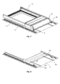
- Fig. 11 is a perspective view of the front surface 120 of a shutter plate 11 taken alone.
- the upper lateral side portion 100 is provided with a tongue 70 and the lower lateral side portion 110 is provided with a groove 71.
- the tongue 70 extending along the upper lateral side portion 100 is configured to engage with a grove 71 of a lower lateral side portion of a neighboring shutter plate 11 when positioned in the screening position.
- Fig. 12 is a corresponding perspective view of the rear surface 130 of a shutter plate 11 taken from another angle showing in more detail the groove 71 extending along the lower lateral side portion 110.
- On each side of the tongue 70 a resilient sealing element 72, 73 extending along the upper 100 and lower 110 lateral side portions is provided. The sealing element 72, 73 ensure that in the screening position when the tongue 70 is guided into the groove 71, the transition between the two shutter plates is sealed to avoid penetration of water between the shutter plates 11.
- Fig. 13 is a partly perspective cross sectional view along the line XIII in Fig. 2 .
- the sealing elements 71, 72 positioned on the upper lateral side portion 100 and constitute a gasket 23.
- the gasket 23 is preferably made of a rubberlike flexible material, which may be deformed when the shutter plates are moved towards each other.
- the sealing elements 72, 73 are configured as part circular rubber walls, which are depressed when the tongue 70 is guided into the groove 71 so that the sealing elements 72, 73 fills out and seal the transition between abutting lateral side sections of the shutter plates 11 when positioned in the screening position. I.e. the situation depicted in Fig.
- FIG. 13 illustrates the sealing elements 72, 73 in a position just before the sealing elements 72, 73 are depressed and the shutter plates are positioned in the screening position. Furthermore, the gaskets 23 ensure that when the shutter plates are pressed together light will not enter between the shutter plates 11.
- the connecting engagement between an upper 100 and a lower 110 lateral side section of adjacent abutting shutter plates also improve the screening properties, but also makes the roof window shutter device 1 more robust in the screening position where e.g. snow may aggregate on the front surface 120 of the shutter plates.
- the connecting members 29 and their connection to the side portions 15 of the shutter plates are configured so that when the shutter plates are moved from the fully screening position as shown in Fig. 2 towards the storage position, an elongate light-admitting aperture 80 is provided between the shutter plates 11 along the upper and lower lateral side sections 100, 110 of adjacent shutter plates 11.
- Fig. 14 shows the connection between two adjacent shutter plates in a situation where the shutter plates are guided by the guide rails 12 towards the storage position.
- the right-hand side of the connecting member 29 is pivotally connected to the side portion 15 close to the lower lateral side portion 110 of a shutter plate.
- the left-hand side of the connecting member 29 is slidably connected to the guide 30 of another neighboring shutter plate and has moved to an end of the groove situated close to the upper lateral side portion of the shutter plate 11.
- the connecting member 29 and the connection of the connecting member 29 to the shutter plates are configured so that an elongate light-admitting aperture 80 is provided between the shutter plates when moved towards the storage position. Besides from providing a light-admitting position wherein the major part of the opening is still screened, this configuration of the connection between the shutter plates allows the shutter plates 11 to be turned and moved during stacking as described above.
- Fig. 15 shows the left-hand side guide rail 12 of Fig. 2 in a perspective view.
- the guide rails 12 are preferably manufactured by extrusion and comprises mounting holes 91 e.g. for a screw for mounting the bottom pieces 14, which serve as end stops for the shutter plates when guided to the screening position.
- the guide rail 12 comprises a guide track 90 with a slide surface 92 on which the side portions 15 of the shutter plates 11 slide when moved along the guide rails.
- the guide track 90 of the guide rail is in communication with the aperture 16 of the top casing so that the shutter plates are securely guided when moved outside the top casing 8.
- the guide rails 12 comprises two tracks in respective communication with the guide tracks 19, 20 of the top casing 8.
- the slide pins 27, 28 of the side portions 15 of the shutter plates may be positioned towards the front surface 120 and the rear surface 110, respectively, so as to be guided in different parallel tracks in the guide rails 12.
- the first guide track 20 in each side of the top casing extends into a corresponding upper track of the guide rails 12, and the second guide track 19 in each side of the top casing 8 extends into a corresponding lower track of the side rails 12.
- the guide rail 12 comprises a mounting rail 93 for mounting on the side members of the frame 2.
- FIG. 16 and 17 another detail of an embodiment of the invention is shown in more detail, namely the different levels of the first slide member 27 and the second slide member 28 relative to the thickness or height direction of the shutter plate.
- the slide members 27, 28 of the shutter plates are positioned in different planes, such that the slide pin 27 is located close to the front surface 120 and the slide pin 28 near the rear side surface 130 of the shutter plates, respectively. This is illustrated by letters a and b, respectively.
- the different levels allow the two slide members 27, 28 to enter safely into the two different tracks 20 (of which the first portion 32 is shown in these Figures) and 19, respectively, when the shutter plates enter the top casing. It is noted that the cross-sections of the slide members 27, 28 do not overlap.
- the tracks could continue along the guide rails also, which increases the secure engagement with the respective track even further.
- there is only one track in the guide rails and the shutter plates are guided on the bottom of the side portions of the shutter plates, corresponding to letter c in Figs 16 and 17 . Forming the guide rails with two tracks as well is of course conceivable.
Landscapes
- Engineering & Computer Science (AREA)
- Structural Engineering (AREA)
- Architecture (AREA)
- Civil Engineering (AREA)
- Operating, Guiding And Securing Of Roll- Type Closing Members (AREA)
- Power-Operated Mechanisms For Wings (AREA)
- Specific Sealing Or Ventilating Devices For Doors And Windows (AREA)
Applications Claiming Priority (1)
| Application Number | Priority Date | Filing Date | Title |
|---|---|---|---|
| DKPA201270092 | 2012-02-28 |
Publications (2)
| Publication Number | Publication Date |
|---|---|
| EP2634352A2 true EP2634352A2 (de) | 2013-09-04 |
| EP2634352A3 EP2634352A3 (de) | 2016-03-30 |
Family
ID=47749721
Family Applications (1)
| Application Number | Title | Priority Date | Filing Date |
|---|---|---|---|
| EP13157129.1A Withdrawn EP2634352A3 (de) | 2012-02-28 | 2013-02-28 | Dachfensterblendenvorrichtung mit gestapelten Blendenplatten |
Country Status (1)
| Country | Link |
|---|---|
| EP (1) | EP2634352A3 (de) |
Cited By (1)
| Publication number | Priority date | Publication date | Assignee | Title |
|---|---|---|---|---|
| CN108018980A (zh) * | 2017-12-30 | 2018-05-11 | 天津檀英科技有限公司 | 用于移动建筑的屋顶 |
Family Cites Families (3)
| Publication number | Priority date | Publication date | Assignee | Title |
|---|---|---|---|---|
| US1886105A (en) * | 1931-02-14 | 1932-11-01 | Clarence E Julin | Window construction |
| DE2623359C3 (de) * | 1975-06-24 | 1981-01-08 | Hokusho Electric Communication Industrial Co., Ltd., Kodaira, Tokio (Japan) | Verschlußvorrichtung für Wandöffnungen o.dgl |
| DE2947501A1 (de) * | 1979-11-24 | 1981-05-27 | Siegfried 7410 Reutlingen Bauer | Ein- und ausfahrbare abdeckvorrichtung, insbesondere rolladen fuer fenster, tueren, tore o.dgl. |
-
2013
- 2013-02-28 EP EP13157129.1A patent/EP2634352A3/de not_active Withdrawn
Cited By (1)
| Publication number | Priority date | Publication date | Assignee | Title |
|---|---|---|---|---|
| CN108018980A (zh) * | 2017-12-30 | 2018-05-11 | 天津檀英科技有限公司 | 用于移动建筑的屋顶 |
Also Published As
| Publication number | Publication date |
|---|---|
| EP2634352A3 (de) | 2016-03-30 |
Similar Documents
| Publication | Publication Date | Title |
|---|---|---|
| US8959837B2 (en) | Automatically sealing panel system | |
| US9109384B2 (en) | Flush lock for casement window | |
| US6161335A (en) | Balance shoe for reducing the size of a pivotable window sash assembly | |
| JP6038505B2 (ja) | 開閉式天窓 | |
| US7370684B2 (en) | Door shutter mechanism | |
| EP2634352A2 (de) | Dachfensterblendenvorrichtung mit gestapelten Blendenplatten | |
| US20140231030A1 (en) | Garage door drive apparatus | |
| CN102549226A (zh) | 用于可转动窗户处窗户固定装置的控制机构处的装置 | |
| US7857031B2 (en) | Guide assembly for overhead sectional door | |
| TW201400688A (zh) | 百葉窗裝置 | |
| EP2540929B1 (de) | Klappladen | |
| CN101492995A (zh) | 门、特别是升滑门,以及门驱动器 | |
| JP2009035893A (ja) | ルーバー装置および建具 | |
| US20220034162A1 (en) | Roller shutter lock assembly | |
| JP3714227B2 (ja) | 扉開閉装置 | |
| EP2307652A1 (de) | Abschirmvorrichtung mit einem verriegelungsmechanismus für eine kippvorrichtung | |
| JP2008196253A (ja) | 開閉装置、および開閉装置のメンテナンス方法 | |
| JP4673683B2 (ja) | 開閉装置 | |
| CN209989724U (zh) | 百叶片的连接装置及道闸 | |
| JP3784647B2 (ja) | 平行突き出し窓 | |
| JP2007040016A (ja) | 可動ルーバー型雨戸 | |
| JP2004270165A (ja) | 跳ね上げ門扉 | |
| JPH0323037Y2 (de) | ||
| EP1518996A1 (de) | Gehäuse für Rollladen | |
| CA2619629C (en) | Guide assembly for overhead sectional door |
Legal Events
| Date | Code | Title | Description |
|---|---|---|---|
| PUAI | Public reference made under article 153(3) epc to a published international application that has entered the european phase |
Free format text: ORIGINAL CODE: 0009012 |
|
| AK | Designated contracting states |
Kind code of ref document: A2 Designated state(s): AL AT BE BG CH CY CZ DE DK EE ES FI FR GB GR HR HU IE IS IT LI LT LU LV MC MK MT NL NO PL PT RO RS SE SI SK SM TR |
|
| AX | Request for extension of the european patent |
Extension state: BA ME |
|
| PUAL | Search report despatched |
Free format text: ORIGINAL CODE: 0009013 |
|
| AK | Designated contracting states |
Kind code of ref document: A3 Designated state(s): AL AT BE BG CH CY CZ DE DK EE ES FI FR GB GR HR HU IE IS IT LI LT LU LV MC MK MT NL NO PL PT RO RS SE SI SK SM TR |
|
| AX | Request for extension of the european patent |
Extension state: BA ME |
|
| RIC1 | Information provided on ipc code assigned before grant |
Ipc: E04D 13/03 20060101ALI20160223BHEP Ipc: E06B 9/06 20060101AFI20160223BHEP |
|
| STAA | Information on the status of an ep patent application or granted ep patent |
Free format text: STATUS: THE APPLICATION IS DEEMED TO BE WITHDRAWN |
|
| 18D | Application deemed to be withdrawn |
Effective date: 20161001 |