EP2633967A1 - Foam duct - Google Patents
Foam duct Download PDFInfo
- Publication number
- EP2633967A1 EP2633967A1 EP13155529.4A EP13155529A EP2633967A1 EP 2633967 A1 EP2633967 A1 EP 2633967A1 EP 13155529 A EP13155529 A EP 13155529A EP 2633967 A1 EP2633967 A1 EP 2633967A1
- Authority
- EP
- European Patent Office
- Prior art keywords
- foam
- duct
- foam duct
- projection
- portions
- Prior art date
- Legal status (The legal status is an assumption and is not a legal conclusion. Google has not performed a legal analysis and makes no representation as to the accuracy of the status listed.)
- Granted
Links
Images





Classifications
-
- B—PERFORMING OPERATIONS; TRANSPORTING
- B29—WORKING OF PLASTICS; WORKING OF SUBSTANCES IN A PLASTIC STATE IN GENERAL
- B29C—SHAPING OR JOINING OF PLASTICS; SHAPING OF MATERIAL IN A PLASTIC STATE, NOT OTHERWISE PROVIDED FOR; AFTER-TREATMENT OF THE SHAPED PRODUCTS, e.g. REPAIRING
- B29C44/00—Shaping by internal pressure generated in the material, e.g. swelling or foaming ; Producing porous or cellular expanded plastics articles
- B29C44/02—Shaping by internal pressure generated in the material, e.g. swelling or foaming ; Producing porous or cellular expanded plastics articles for articles of definite length, i.e. discrete articles
- B29C44/12—Incorporating or moulding on preformed parts, e.g. inserts or reinforcements
- B29C44/1228—Joining preformed parts by the expanding material
- B29C44/1242—Joining preformed parts by the expanding material the preformed parts being concentric
-
- B—PERFORMING OPERATIONS; TRANSPORTING
- B60—VEHICLES IN GENERAL
- B60H—ARRANGEMENTS OF HEATING, COOLING, VENTILATING OR OTHER AIR-TREATING DEVICES SPECIALLY ADAPTED FOR PASSENGER OR GOODS SPACES OF VEHICLES
- B60H1/00—Heating, cooling or ventilating devices
-
- F—MECHANICAL ENGINEERING; LIGHTING; HEATING; WEAPONS; BLASTING
- F16—ENGINEERING ELEMENTS AND UNITS; GENERAL MEASURES FOR PRODUCING AND MAINTAINING EFFECTIVE FUNCTIONING OF MACHINES OR INSTALLATIONS; THERMAL INSULATION IN GENERAL
- F16L—PIPES; JOINTS OR FITTINGS FOR PIPES; SUPPORTS FOR PIPES, CABLES OR PROTECTIVE TUBING; MEANS FOR THERMAL INSULATION IN GENERAL
- F16L9/00—Rigid pipes
- F16L9/003—Rigid pipes with a rectangular cross-section
-
- B—PERFORMING OPERATIONS; TRANSPORTING
- B29—WORKING OF PLASTICS; WORKING OF SUBSTANCES IN A PLASTIC STATE IN GENERAL
- B29C—SHAPING OR JOINING OF PLASTICS; SHAPING OF MATERIAL IN A PLASTIC STATE, NOT OTHERWISE PROVIDED FOR; AFTER-TREATMENT OF THE SHAPED PRODUCTS, e.g. REPAIRING
- B29C49/00—Blow-moulding, i.e. blowing a preform or parison to a desired shape within a mould; Apparatus therefor
- B29C49/02—Combined blow-moulding and manufacture of the preform or the parison
- B29C49/04—Extrusion blow-moulding
-
- B—PERFORMING OPERATIONS; TRANSPORTING
- B32—LAYERED PRODUCTS
- B32B—LAYERED PRODUCTS, i.e. PRODUCTS BUILT-UP OF STRATA OF FLAT OR NON-FLAT, e.g. CELLULAR OR HONEYCOMB, FORM
- B32B1/00—Layered products having a non-planar shape
- B32B1/08—Tubular products
-
- F—MECHANICAL ENGINEERING; LIGHTING; HEATING; WEAPONS; BLASTING
- F16—ENGINEERING ELEMENTS AND UNITS; GENERAL MEASURES FOR PRODUCING AND MAINTAINING EFFECTIVE FUNCTIONING OF MACHINES OR INSTALLATIONS; THERMAL INSULATION IN GENERAL
- F16L—PIPES; JOINTS OR FITTINGS FOR PIPES; SUPPORTS FOR PIPES, CABLES OR PROTECTIVE TUBING; MEANS FOR THERMAL INSULATION IN GENERAL
- F16L59/00—Thermal insulation in general
- F16L59/14—Arrangements for the insulation of pipes or pipe systems
-
- F—MECHANICAL ENGINEERING; LIGHTING; HEATING; WEAPONS; BLASTING
- F24—HEATING; RANGES; VENTILATING
- F24F—AIR-CONDITIONING; AIR-HUMIDIFICATION; VENTILATION; USE OF AIR CURRENTS FOR SCREENING
- F24F13/00—Details common to, or for air-conditioning, air-humidification, ventilation or use of air currents for screening
- F24F13/02—Ducting arrangements
-
- B—PERFORMING OPERATIONS; TRANSPORTING
- B29—WORKING OF PLASTICS; WORKING OF SUBSTANCES IN A PLASTIC STATE IN GENERAL
- B29K—INDEXING SCHEME ASSOCIATED WITH SUBCLASSES B29B, B29C OR B29D, RELATING TO MOULDING MATERIALS OR TO MATERIALS FOR MOULDS, REINFORCEMENTS, FILLERS OR PREFORMED PARTS, e.g. INSERTS
- B29K2105/00—Condition, form or state of moulded material or of the material to be shaped
- B29K2105/04—Condition, form or state of moulded material or of the material to be shaped cellular or porous
-
- B—PERFORMING OPERATIONS; TRANSPORTING
- B29—WORKING OF PLASTICS; WORKING OF SUBSTANCES IN A PLASTIC STATE IN GENERAL
- B29L—INDEXING SCHEME ASSOCIATED WITH SUBCLASS B29C, RELATING TO PARTICULAR ARTICLES
- B29L2023/00—Tubular articles
- B29L2023/22—Tubes or pipes, i.e. rigid
-
- Y—GENERAL TAGGING OF NEW TECHNOLOGICAL DEVELOPMENTS; GENERAL TAGGING OF CROSS-SECTIONAL TECHNOLOGIES SPANNING OVER SEVERAL SECTIONS OF THE IPC; TECHNICAL SUBJECTS COVERED BY FORMER USPC CROSS-REFERENCE ART COLLECTIONS [XRACs] AND DIGESTS
- Y10—TECHNICAL SUBJECTS COVERED BY FORMER USPC
- Y10S—TECHNICAL SUBJECTS COVERED BY FORMER USPC CROSS-REFERENCE ART COLLECTIONS [XRACs] AND DIGESTS
- Y10S138/00—Pipes and tubular conduits
- Y10S138/09—Cellular
-
- Y—GENERAL TAGGING OF NEW TECHNOLOGICAL DEVELOPMENTS; GENERAL TAGGING OF CROSS-SECTIONAL TECHNOLOGIES SPANNING OVER SEVERAL SECTIONS OF THE IPC; TECHNICAL SUBJECTS COVERED BY FORMER USPC CROSS-REFERENCE ART COLLECTIONS [XRACs] AND DIGESTS
- Y10—TECHNICAL SUBJECTS COVERED BY FORMER USPC
- Y10S—TECHNICAL SUBJECTS COVERED BY FORMER USPC CROSS-REFERENCE ART COLLECTIONS [XRACs] AND DIGESTS
- Y10S138/00—Pipes and tubular conduits
- Y10S138/11—Shape
-
- Y—GENERAL TAGGING OF NEW TECHNOLOGICAL DEVELOPMENTS; GENERAL TAGGING OF CROSS-SECTIONAL TECHNOLOGIES SPANNING OVER SEVERAL SECTIONS OF THE IPC; TECHNICAL SUBJECTS COVERED BY FORMER USPC CROSS-REFERENCE ART COLLECTIONS [XRACs] AND DIGESTS
- Y10—TECHNICAL SUBJECTS COVERED BY FORMER USPC
- Y10T—TECHNICAL SUBJECTS COVERED BY FORMER US CLASSIFICATION
- Y10T428/00—Stock material or miscellaneous articles
- Y10T428/13—Hollow or container type article [e.g., tube, vase, etc.]
- Y10T428/1352—Polymer or resin containing [i.e., natural or synthetic]
- Y10T428/1376—Foam or porous material containing
Definitions
- the present invention relates to a foam duct including foam resin.
- a foam duct including foam resin is employed as the duct for vehicles such as cars.
- the foam duct is less heavy than a duct including non-foam resin and is hence suitable for vehicles the weight of which is desired to be reduced from a viewpoint of fuel efficiency and the like.
- the foam duct of this kind is ordinarily produced in the following molding method.
- a foam resin prepared by melting and kneading various materials is extruded from an annular die of an extruding machine to form a cylindrical foam parison.
- the foam parison is clamped by a metallic mold and then air is blown into the foam parison in the metallic mold to push the foam parison against a cavity of the metallic mold to thereby shape the foam parison.
- the foam parison is then extended to be molded in a contour of the cavity.
- the molded item having the cavity contour is cooled.
- the mold is then opened.
- the molded item is removed and undesired portions thereof are removed, to thereby obtain a desired foam duct.
- Patent Document for the foam duct includes, for example.
- Patent Document 1 Japanese Patent Laid-Open Ser. No. 2011-194700
- Patent Document 2 Japanese Patent Laid-Open Ser. No. 2011-116120 .
- Patent Document 1 it is possible, by defining each material of the foam resin, to mold a lightweight foam duct having a sufficient property against low-temperature shock by using less expensive material composition and by decreasing the kinds of mixing materials.
- Patent Document 2 it is possible, by defining polypropylene-based resins constituting the foam resin, to mold a foam duct with a high expansion ratio in which pinholes are not easily formed even with a high blow ratio.
- the present invention seeks to provide for a foam duct having advantages over known foam ducts.
- the present invention has an aspect as follows.
- the foam duct in accordance with the present invention is a foam duct including foam resin and includes a cylindrical portion having an external contour of a polygonal shape and a projection in an inner surface side of the cylindrical portion, and thickness of wall portions of the cylindrical portion is larger in a portion in which the projection is formed than in a portion in which the projection is not formed.
- the foam duct 200 of the present embodiment is a foam duct 200 including foam resin.
- the foam duct 200 has an aspect in which the foam duct 200 includes a cylindrical portion (corresponding to the connecting portion 206) having a polygonal outer contour and includes projection 204 on an inner surface side of the cylindrical portion 206; and thickness of wall portions of the cylindrical portion is larger in a portion in which the projection 204 is formed than in a portion in which the projection 204 is not formed.
- the foam duct 200 of the present embodiment includes the projection 204 on an inner surface side of the cylindrical portion 206. Hence, it is possible to improve rigidity of the foam duct 200. Also, as shown in FIGS. 1 to 4 , the foam duct 200 includes the cylindrical portions 206 in an edge portion of the opening. Hence, for example, when an inner surface side of the foam duct 200 is engaged with an outer surface side of another member 300 to connect the foam duct to the member, the projection 204 makes contact with an outer surface of the member 300. This prevents the event in which the foam duct 200 is easily removed from the member 300.
- the projection 204 includes foam resin. Hence, in the state shown in FIG. 2 , when the outer surface of the member 300 makes contact with the projection 204, the projection 204 deforms along the outer surface contour of the member 300 to thereby hold the member 300 as shown in FIG. 4 .
- FIGS. 3 and 4 schematically show a gap between the outer surface of the member 300 and the inner surface of the cylindrical portions 206.
- a packing member 400 such as foam urethane is pasted around the outer surface of the member 300, and the member 300 around which the packing member 400 is pasted is inserted in the inner surface side of the cylindrical portion 206 for the connection therebetween. This makes it possible to prevent occurrence of the gap between the outer surface of the member 300 and the inner surface of the cylindrical portions 206.
- the external surface contour of the member 300 itself is designed to follow the inner surface contour of the cylindrical portion 206, to thereby prevent occurrence of the gap between the outer surface of the member 300 and the inner surface of the cylindrical portion 206.
- a connecting portion 206 disposed in an opening edge portion of the foam duct 200 is employed as an example of the cylindrical portions 206 having a polygonal outer contour.
- the cylindrical portion 206 is not limited to the connecting portion 206 disposed in an opening edge portion of the foam duct 200. It is also possible that a portion other than the opening edge portion is formed in a polygonal contour such that the projection 204 is disposed on the inner surface side of the polygonal-contour portion (cylindrical portion).
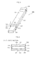
- FIG. 1 shows a configuration example of the foam duct 200.
- FIG. 2 shows an example of an X-X' cross-sectional configuration perpendicular to the hollow extending direction of the connecting portion 206 shown in FIG. 1 .
- FIG. 3 shows a state in which another member 300 is connected to the connecting portion 206 of the foam duct 200.
- FIG. 4 shows an example of an X-X' cross-sectional configuration perpendicular to the hollow extending direction of the connecting portion 206 shown in FIG. 2 .
- the foam duct 200 is molded by blowing foam resin with an expansion ratio of 2.0 or more in independent bubble structure including a plurality of foamed cells.
- the foam duct 200 includes a first wall portion 201, a second wall portion 202 opposing the first wall portion 201 with a gap therebetween, and a peripheral wall 203 connecting circumferences of the first and second wall portions 201 202 to each other.
- parting lines PL1 and PL2 are formed in the peripheral wall 203.
- the foam resin for the foam duct 200 there may be employed, for example, a resin prepared by adding a foaming agent to a polypropylene-based resin having an equilibrium compliance of 2.0 to 6.0 (10 -3 xPa -1 ).
- a foaming agent there may be used inorganic physical foaming agents such as air, carbon dioxide, nitrogen dioxide, and water; organic physical foaming agents such as butane, pentane, hexane, dichloromethane, and dichloroethane; and chemical foaming agents such as sodium bicarbonate, citric acid, sodium citrate, and azodicarbonamide.
- a physical foaming agent in combination with a chemical foaming agent.
- the foam resin for the foam duct 200 is not limited to these materials, but any known foaming agent is also applicable.
- the foam dust 200 includes a hollow portion 205 in an inner surface of the duct such that fluid such as air flows through the hollow portions 205.
- a connecting portion 206 having a polygonal external contour is disposed to connect to another member 300 (reference is to be made to FIGS. 3 and 4 ).
- the opening of the connecting portion 206 in this embodiment has a rectangular contour to configure a female-type connecting portions 206 as shown in FIGS. 3 and 4 such that an inner surface side of the connecting portion 206 engages with an outer surface side of the member 300 for the connection therebetween.
- the foam duct 200 includes a projection 204 in an inner surface side of the connecting portions 206 as shown in FIG. 2 . Thickness of the wall portion configuring the connecting portion 206 is larger in the portion in which the projection 204 is formed than in the portion in which the projection 204 is not formed.
- the first and second wall portions 201 and 202 of the foam duct 200 have a mean thickness ranging from 2.0 mm to 3.0 mm.
- the mean thickness is calculated as below. First, in crosssections at three positions including the center and the first and second ends (upper and lower ends) of the foam duct 200, measurement is conducted by use of a pair of slide calipers to obtain thickness of each portion at six positions in total at which a perpendicular bisector of a straight line between two mold splitting points intersects the first and second wall portions 201 and 202. The mean value of the six measured values thus obtained is employed as the mean thickness.
- the difference in thickness between the portion in which the projection 204 is not formed and the portion in which the projection 204 is formed ranges from 0.5 mm to 1.0 mm.
- the thickness of the crosssectional contour of the connecting portion 206 takes the maximum value in the portion in which the projection 204 is formed.
- the blow ratio is favorably 0.2 or more and is more favorably 0.4 or more.
- the blow ratio of the connecting portion 206 is a ratio (B/A), taken in the crosssection perpendicular to the hollow extending direction, between length A of a straight line connecting parting lines PL1 and PL2 to each other and distance B from straight line A to an outer surface of the wall portion most apart therefrom.
- the blow ratio is 0.2 in FIG. 2 .
- the foam duct 200 of the present embodiment includes the projection 204 in an inner surface side of the connecting portion 206.
- the projection 204 makes contact with the outer surface side of the member 300.
- the projection 204 includes foam resin, when the projection 204 makes contact wit the outer surface side of the member 300 in the state shown in FIG. 2 , the projection 204 deforms along the outer surface contour of the member 300, to hold the member 300 as shown in FIG. 4 .
- the foam duct 200 includes a projection 204 not only in the opening edge portions, but also in an inner surface of the duct in other than opening edge portions, to thereby improve rigidity of the foam duct 200.
- wall portions of the foam duct 200 become generally thin, the foam duct 200 is easily deflected.
- vibration occurs depending on cases. This problem is more remarkable when the foam duct 200 has a complex contour in which the foam duct 200 deflects in three-directional directions.
- rigidity of the foam duct 200 is improved by disposing the projection 204 in the duct inner surface.
- the projection 204 is favorably disposed in a continuous fashion along the channel direction of the fluid flowing through the inside of the foam duct 200. This further prevents deflection of the foam duct 200 and occurrence of vibration in the foam duct 200.
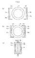
- FIG. 5 shows a state in which a cylindrical foam parison 14 is extruded from an annular die 11.
- FIGS. 6 and 7 show states of the foam parison 14 viewed from the annular die 11 of FIG. 5 .
- FIG. 5 shows, various materials, for example, a resin prepared by adding a foaming agent to a polypropylene-based resin having an equilibrium compliance of 2.0 to 6.0 (10 -3 xPa -1 ) are melted and kneaded into foam resin.
- the foam resin is extruded from the annular die 11 of an extruding machine to form a cylindrical foam parison 14.
- the foam parison 14 is placed between split metallic mold blocks 12a and 12b. As a result, it is possible to arrange the foam parison 14 between the split metallic mold blocks 12a and 12b as shown in FIGS. 5 and 6(a) .
- the mold blocks 12a and 12b are moved to the side of the foam parison 14 as shown in FIG. 6(b) such that cavities 10a and 10b respectively of the mold blocks 12a and 12b make contact with the foam parison 14.
- Portions of the foam parison 14 at positions 15a and 15b first brought into contact respectively with the cavities 10a and 10b of the mold blocks 12a and 12b are cooled and hence become harder than the other portions of the foam parison 14. These portions 15a and 15b are used to form projections 204.
- the mold blocks 12a and 12b are driven to the clamping state and the foam parison 14 is clamped between the mold blocks 12a and 12b. Both ends of the foam parison 14 are nipped by pinch-off portions 13a and 13b, to thereby accommodate the foam parison 14 in a space between the cavities 10 and 10b of the mold blocks 12a and 12b.
- a blow-in needle and a blow-out needle are inserted in the foam parison 14.
- Compressed gas such as air is blown from the blow-in needle into the foam parison 14.
- the air passes through the inside of the foam parison 14 and is blown out via the blow-out needle, to thereby conduct the blow molding at a predetermined blow pressure.
- FIG. 7(a) the foam parison 14 is pushed against wall surfaces of the cavities 10a and 10b to be extended along contours of the cavities 10a and 10b.
- the portions of the foam parison 14 at positions 15a and 15b first brought into contact respectively with the cavities 10a and 10b of the mold blocks 12a and 12b are cooled and hence become harder than the other portions of the foam parison 14, and have already made contact with the cavities 10a and 10b.
- FIG. 7(a) shows the portions at the positions 15a and 15b are less extended, and the portions at the other positions are extended along the contours of the cavities 10a and 10b.
- the projection 204 is formed at the positions 15a and 15b where the portions of the foam parison 14 are first brought into contact with the cavities 10a and 10b of the mold blocks 12a and 12b in the state shown in FIG. 6(b) .
- the portions not being brought into contact with the cavities 10a and 10b in the state shown in FIG. 6(b) are extended, to form portions which are thinner than the portions in which the projection 204 is formed.
- the thickness of the wall portion constituting the connecting portion 206 is greater in the portion in which the projection 204 is formed than in the portion in which the projection 204 is not formed.
- the blow molding When the blow molding is carried out at a predetermined blow pressure, it is possible to dispose a heat regulating unit to heat the compressed gas, which is supplied from the blow-in needle into the foam parison 14, to a predetermined temperature. Since the compressed gas supplied into the foam parison 14 is at a predetermined temperature, the foaming agent contained in the foam parison 14 easily foams.
- the predetermined temperature is favorably set to a temperature suitable to make the foaming agent easily foam.
- the molding without disposing the heat regulating unit. That is, the compressed gas supplied into the foam parison 14 is at a room temperature. Since it is not required to dispose the heat regulating unit to adjust the temperature of the compressed gas, the foam duct 200 can be molded at a low cost. Since the foam duct 200 is cooled after the blow molding and the blow molding is conducted at a room temperature, the period of time required to cool the foam duct 200 after the blow molding is reduced.
- the molding process it is not required to simultaneously conduct the process to blow compressed gas into the foam parison 1 and the process to produce a negative pressure outside the foam parison 1. These processes may be performed with an interval of time therebetween. Or, it is possible to conduct only one of these processes to carry out the molding in which the foam parison 14 is pushed against the wall surfaces of the cavities 10a and 10b to be extended according to the contours of the cavities 10a and 10b, to thereby mold a foam duct 200 including projection 204 in the duct inner surface.
- compressed gas such as air is supplied from the blow-in needle into the foam parison 14.
- the air passes through the foam parison 14 to be exhausted from the blow-out needle, to cool the foam duct 200 at a predetermined blow pressure.
- the compressed gas supplied from the blow-in needle into the foam parison 14 is set to a temperature ranging from 10°C to 30°C, preferably to a room temperature, e.g., 23°C.
- a room temperature e.g. 23°C.
- the heat regulating unit is disposed to set the compressed gas to a temperature lower than the room temperature, the period of time required to cool the foam duct 200 is reduced.
- the cooling period of time favorably ranges from 30 seconds to 80 seconds although depending on the temperature of the compressed gas.
- the cylindrical foam parison 14 is arranged between the mold blocks 12a and 12b as shown in FIG. 6(a) and the cavities 10a and 10b of the mold blocks 12a and 12b are brought into contact with the foam parison 14, to harden the portions 15a and 15b of the foam parison 14 first brought into contact with the cavities 10a and 10b as shown in FIG. 6(b) .
- FIG. 6(c) shows, the mold blocks 12a and 12b are driven to the clamping state.
- the blow-in and blow-out needles are inserted into the foam parison 14 to carry out the blow molding at a predetermined blow pressure, to extend the foam parison 14 according to the contours of the cavities 10a and 10b as shown in FIG. 7(a) .
- the projection 204 is formed in the portions 15a and 15b first brought into contact with the cavities 10a and 10b in the state shown in FIG. 6(b) .
- the portions not brought into contact with the cavities 10a and 10b in the state of FIG. 6(b) are extended to form thinner portions.
- the foam duct 200 of the present embodiment includes the projections 204 in the duct inner surface as shown in FIG. 2 , it is possible to improve rigidity of the foam duct 200. Also, as FIGS. 3 and 4 show, when another member 300 is inserted in an inner surface side of the connecting portion 206 to engage the inner surface side of the connecting portions 206 with an outer surface side of the member 300 for the connection therebetween, the outer surface side of the member 300 makes contact with the projections 204, to thereby prevent the event in which the foam duct 200 is easily removed from the member 300.
- the projections 204 include foam resin. Hence, when the outer surface side of the member 300 makes contact with the projection 204 in the state shown in FIG. 2 , the projections 204 deform according to the outer surface contour of the member 300, to hold the member 300 as shown in FIG. 4 .
- a gap exists between the inner surface of the connecting portion 206 and the outer surface of the member 300 as shown in FIGS. 3 and 4 .
- a packing member 400 such as foam urethane is pasted around the outer circumferential surface of the member 300, and the member 300 around which the packing member 400 is pasted is inserted in the inner surface side of the cylindrical portion 206 for the connection therebetween as shown in FIG. 8(b) .
- FIG. 8(a) a packing member 400 such as foam urethane is pasted around the outer circumferential surface of the member 300, and the member 300 around which the packing member 400 is pasted is inserted in the inner surface side of the cylindrical portion 206 for the connection therebetween as shown in FIG. 8(b) .
- FIG. 8 (c) shows an example of an X-X' cross-sectional configuration perpendicular to the hollow extending direction of the connecting portion 206 shown in FIG. 8(b) .
- the outer surface contour of the member 300 itself is designed to follow the inner surface contour of the connecting portion 206, to thereby prevent occurrence of the gap between the outer surface of the member 300 and the inner surface of the connecting portion 206.
- the connecting portion 206 includes no branch as shown in FIG. 1 .
- the connecting portion 206 includes two or more branches as shown in FIG. 9 . Also in the situation of the configuration example shown in FIG. 9 , projections 204 are formed in the connecting portion 206. As a result, it is possible to prevent the event in which the foam duct 200 is easily removed from another member 300.
- FIGS. 9 to 13 description will be given of the foam duct 200 of the present embodiment. In the description below, an "inpane" duct will be employed as an example of the foam duct 200.
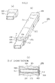
- FIG. 9 shows a configuration example of the foam duct 200.
- FIG. 9(a) shows the side of a first wall portion 201 of the foam duct 200.
- FIG. 9(b) shows the side of a second wall portions 202 of the foam duct 200.
- FIG. 10 shows a configuration example of a connecting portion 206 of the foam duct 200 shown in FIG. 9(a) .
- FIG. 10(a) is an external perspective view of the connecting portion 206.
- FIG. 10(b) shows an example of an X-X' cross-sectional configuration perpendicular to the hollow extending direction of the connecting portion 206.
- FIG. 11 shows a configuration example in a state in which another member 300 is connected to the connecting portion 206.
- the foam duct 200 of the present embodiment includes a first wall portion 201 and a second wall portion 202 which are welded onto each other via parting lines PL1 and PL2.
- the foam duct 200 includes a hollow portion 205 in the duct such that fluid such as air flows through the hollow portion 205.
- the foam duct 200 also includes a connecting portion 206 to connect to another member 300.
- the connecting portion 206 includes two or more branches.
- the opening of the connecting portion 206 in this embodiment has a rectangular contour to configure a female-type connecting portion 206 as shown in FIG. 11 such that an inner surface side of the connecting portion 206 engages with an outer surface side of the member 300 for the connection therebetween.
- the foam duct 200 include a projection 204 in an inner surface side of the connecting portion 206 as shown in FIG. 10 . Thickness of the wall portion configuring the connecting portion 206 is larger in the portion in which the projection 204 is formed than in the portion in which the projection 204 is not formed.
- the first and second wall portions 201 and 202 of the foam duct 200 have a mean thickness ranging from 2.0 mm to 3.0 mm.
- the difference in thickness between the portion in which the projection 204 is not formed and the portion in which the projection 204 is formed ranges from 0.5 mm to 1.0 mm.
- the mean thickness is mean thickness calculated by use of thickness values measured at an equal interval of about 100 mm in the hollow extending direction of the foam duct 200.
- the hollow extending direction is a direction in which the hollow portions 205 extends in the foam duct 20 and is the direction in which fluid flows.
- the mean thickness on the side of the first wall portion 201 of the foam duct 200 is mean thickness calculated by use of thickness values measured at 18 positions, i.e., positions 11 to 19 and 20 to 28 on the side of the first wall portion 201 of the foam duct 200 shown in FIG. 9(a) .
- the mean thickness on the side of the second wall portion 202 is mean thickness calculated by use of thickness values measured at 16 positions, i.e., positions 31 to 38 and 39 to 46 on the side of the second wall portion 202 of the foam duct 200 shown in FIG. 9(b) .
- the mean thickness of the overall foam duct 200 is mean thickness calculated by use of the mean thickness on the side of the first wall portion 201 and the mean thickness on the side of the second wall portion 202.
- the thickness takes the maximum value in the portion in which the projection 204 is formed and the minimum value in the portion most apart from the line connecting the parting lines PL1 and PL2 to each other.
- the blow ratio of the connecting portion 206 is a ratio (B/A), taken in the crosssection perpendicular to the hollow extending direction, between length A of the straight line connecting parting lines PL1 and PL2 to each other and distance B from straight line A to an outer surface of the wall portion most apart therefrom.
- the blow ratio is 0.4 in FIG. 10(b) .
- the foam duct 200 of the present embodiment includes the projection 204 on an inner surface side of the connecting portions 206.
- the projection 204 makes contact with the outer surface side of the member 300.
- the foam duct 200 includes projection 204 in the vicinity of the parting lines PL1 and PL2, it is possible to more stably hold the member 300 inserted in the connecting portion 206 when compared with the first embodiment.
- the projection 204 includes foam resin, when the projection 204 makes contact with the outer surface side of the member 300 in the state shown in FIG.
- the projection 204 deforms along the outer surface contour of the member 300 to stably hold the member 300 as shown in FIG. 11 . It is hence possible to prevent the event in which the foam duct 200 is easily removed from the member 300.
- the foam duct 200 of the present embodiment includes a projection 204 not only in the connecting portion 206 of the opening edge portion, but also in the duct inner surface other than the opening edge portion, to thereby improve rigidity of the foam duct 200.
- the projection 204 is favorably disposed in a continuous fashion along the channel direction (hollow extending direction) of the fluid flowing through the inside of the foam duct 200. This further prevents deflection of the foam duct 200 and occurrence of vibration in the foam duct 200.
- FIG. 5 shows, various materials, for example, a resin prepared by adding a foaming agent to a polypropylene-based resin having an equilibrium compliance of 2.0 to 6.0 (10 -3 xPa -1 ) are melted and kneaded into foam resin.
- the foam resin is extruded from the annular die 11 of an extruding machine to form a cylindrical foam parison 14.
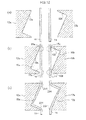
- the foam parison is arranged between split metallic mold blocks 12a and 12b. As a result, it is possible to place the foam parison 14 between the split metallic mold blocks 12a and 12b as shown in FIGS. 5 and 12(a) .
- the mold blocks 12a and 12b are moved to the side of the foam parison 14 as shown in FIG. 12(b) such that cavities 10a and 10b respectively of the mold blocks 12a and 12b make contact with the foam parison 14, to form sealed spaces 16a and 16b by the foam parison 14 and the cavities 10a and 10b.
- Portions of the foam parison 14 at positions 15a and 15b first brought into contact respectively with the cavities 10a and 10b of the mold blocks 12a and 12b are cooled and hence become harder than the other portions of the foam parison 14.
- the projections 204 are formed by use of the portions 15a and 15b.
- the suction process is performed via the mold blocks 12a and 12b for the sealed spaces 16a and 16b such that the foam parison 14 is pushed against the cavities 10a and 10b, to shape the foam parison 14 in the contour along the cavities 10a and 10b as shown in FIG. 12(c) .
- a vacuum suction chamber not shown, is disposed to be connected via suction holes to the cavities 10a and 10b.
- the portions of the foam parison 14 at positions 15a and 15b first brought into contact with the cavities 10a and 10b of the mold blocks 12a and 12b are cooled and hence become harder than the other portions of the foam parison 14, and have already made contact with the cavities 10a and 10b.
- FIG. 12(c) shows the portions at the positions 15a and 15b are less extended, and the portions at the other positions are extended along the contours of the cavities 10a and 10b.
- FIG. 12(c) shows, projections 204 are formed at the positions 15a and 15b where the portions of the foam parison 14 are first brought into contact with the cavities 10a and 10b of the mold blocks 12a and 12b in the state shown in FIG. 12(b) .
- the portions not being brought into contact with the cavities 10a and 10b in the state shown in FIG. 12(b) are extended, to form portions which are thinner than the portions in which the projections 204 are formed.
- FIG. 13(a) shows, the mold blocks 12a and 12b are driven to the clamping state and the foam parison 14 is clamped between the mold blocks 12a and 12b. Both ends of the foam parison 14 are nipped by the mold blocks 12a and 12b, to accommodate the foam parison 14 in a space between the cavities 10 and 10b of the mold blocks 12a and 12b. Further, peripheral portions of the form parison 14 are welded onto each other, to thereby form the parting lines PL1 and PL2.
- the cylindrical foam parison 14 is arranged between the mold blocks 12a and 12b as shown in FIG. 12(a) , and the cavities 10a and 10b of the mold blocks 12a and 12b are brought into contact with the foam parison 14, to harden the portions 15a and 15b of the foam parison 14 first brought into contact with the cavities 10a and 10b as shown in FIG. 12(b) .
- FIG. 12(c) shows, the foam parison 14 is shaped into the contours of the cavities 10a and 10b, to extend the foam parison 14 according to the contours of the cavities 10a and 10b.
- the projection 204 is formed in the portions 15a and 15b first brought into contact with the cavities 10a and 10b in the state shown in FIG. 12(b) , and the portions not brought into contact with the cavities 10a and 10b in the state of FIG. 12(b) are extended to form thinner portions.
- peripheral portions of the form parison 14 are welded to each other, to thereby form the parting lines PL1 and PL2.
- the foam duct 200 of the present embodiment includes the projections 204 in the duct inner surfaces as shown in FIG. 10 , it is possible to improve rigidity of the foam duct 200.
- FIG. 11 shows, when another member 300 is inserted in an inner surface side of the connecting portion 206 to engage the inner surface side of the connecting portion 206 with an outer surface side of the member 300 for the connection therebetween, the outer surface side of the member 300 makes contact with the projections 204, to thereby prevent the event in which the foam duct 200 is easily removed from the member 300.
- the projections 204 include foam resin. Hence, when the outer surface side of the member 300 makes contact with the projection 204 in the state shown in FIG. 10 , the projection 204 deform according to the outer surface contours of the member 300, to hold the member 300 as shown in FIG. 11 .
- a packing member 400 such as foam urethane is pasted around the outer circumferential surface of the member 300, and the member 300 around which the packing member 400 is pasted is inserted in the inner surface side of the cylindrical portion 206.
- the outer surface contour of the member 300 itself is designed to follow the inner surface contour of the connecting portions 206, to insert the member 300 into the inner surface of the connecting portion 206.
- the foam duct 200 includes a projection 204 in the duct inner surface.
- the foam duct 200 shown in FIGS. 9 and 10 can be molded by using two foam resin sheets (each having the contour of a sheet) in place of the cylindrical foam parison 14.
- the foam resin sheets are employed, it is possible to adjust sheet thickness of each foam resin sheet.
- the thickness may differ between the first and second wall portions 201 and 202, and the contour of the projection 204 may also differ between the first and second wall portions 201 and 202.
- the contours of the cavities 10a and 10b of the mold blocks 12a and 12b employed to mold the foam duct 200 are not limited to those described above.
- the cavities 10a and 10b may be in any contour only if it is possible to form the projection 204 and the cavities 10a and 10b first make contact with part of the foam parison 14 or part of the foam resin sheet.
Landscapes
- Engineering & Computer Science (AREA)
- Mechanical Engineering (AREA)
- General Engineering & Computer Science (AREA)
- Manufacturing & Machinery (AREA)
- Chemical & Material Sciences (AREA)
- Combustion & Propulsion (AREA)
- Physics & Mathematics (AREA)
- Thermal Sciences (AREA)
- Blow-Moulding Or Thermoforming Of Plastics Or The Like (AREA)
- Air-Conditioning For Vehicles (AREA)
- Molding Of Porous Articles (AREA)
Abstract
Description
- The present invention relates to a foam duct including foam resin.
- As the duct for vehicles such as cars, a foam duct including foam resin is employed. The foam duct is less heavy than a duct including non-foam resin and is hence suitable for vehicles the weight of which is desired to be reduced from a viewpoint of fuel efficiency and the like.
- The foam duct of this kind is ordinarily produced in the following molding method. First, a foam resin prepared by melting and kneading various materials is extruded from an annular die of an extruding machine to form a cylindrical foam parison. The foam parison is clamped by a metallic mold and then air is blown into the foam parison in the metallic mold to push the foam parison against a cavity of the metallic mold to thereby shape the foam parison. The foam parison is then extended to be molded in a contour of the cavity. Thereafter, the molded item having the cavity contour is cooled. The mold is then opened. The molded item is removed and undesired portions thereof are removed, to thereby obtain a desired foam duct.
- Document for the foam duct includes, for example. Patent Document 1 (Japanese Patent Laid-Open Ser. No.
2011-194700 2011-116120 - According to Patent Document 1, it is possible, by defining each material of the foam resin, to mold a lightweight foam duct having a sufficient property against low-temperature shock by using less expensive material composition and by decreasing the kinds of mixing materials.
- According to Patent Document 2, it is possible, by defining polypropylene-based resins constituting the foam resin, to mold a foam duct with a high expansion ratio in which pinholes are not easily formed even with a high blow ratio.
- In the foam duct described above, it is favorable to reduce thickness of wall portions of the foam duct, to lower the weight thereof. However, when wall portions of the foam duct become thin, rigidity of the foam duct decreases and the foam duct is easily deflected, and it is difficult to attach the foam duct onto a member of a car and the like. Also, when fluid such as gas Hows on an inner surface of the foam duct, vibration occurs depending on cases. Incidentally, in the foam ducts described in Patent Document 1 and Patent Document 2, inner walls of the foam duct are smoothed. However, in a situation wherein inner walls of a foam duct are smoothed as in the foam ducts described in Patent Document 1 and Patent Document 2, when wall portions of the foam duct become thin, rigidity of the foam duct decreases, and there exists a fear of occurrence of the problem described above. Also, in a situation wherein inner walls of edge portions of the opening of the foam duct are smoothed, for example, when an inner surface side of the foam duct is engaged with an outer surface side of another member to connect the foam duct to the member, a gap takes place between the inner surface side of the foam duct and the outer surface side of the member and the foam duct is easily removed from the member in some cases.
- The present invention seeks to provide for a foam duct having advantages over known foam ducts.
- It is a particular object of the present invention, which has been made in consideration of the situation above, to provide a foam duct in which it is possible to increase rigidity.
- To achieve the object, the present invention has an aspect as follows.
- The foam duct in accordance with the present invention is a foam duct including foam resin and includes a cylindrical portion having an external contour of a polygonal shape and a projection in an inner surface side of the cylindrical portion, and thickness of wall portions of the cylindrical portion is larger in a portion in which the projection is formed than in a portion in which the projection is not formed.
- In accordance with the present invention, it is possible to increase rigidity of the foam duct.
-
FIG. 1 is a diagram showing a configuration example of afoam duct 200 in a first embodiment; -
FIG. 2 is a diagram showing an example of an X-X' cross-sectional configuration perpendicular to the hollow extending direction of a connectingportion 206 of thefoam duct 200 shown inFIG. 1 ; -
FIG. 3 is a diagram showing a state in which anothermember 300 is connected to the connectingportion 206 of thefoam duct 200 shown inFIG. 1 ; -
FIG. 4 is a diagram showing an example of an X-X' cross-sectional configuration perpendicular to the hollow extending direction of the connectingportion 206 shown inFIG. 3 ; -
FIG. 5 is a first diagram showing an example of the molding method of thefoam duct 200; -
FIG. 6 is a second diagram showing an example of the molding method of thefoam duct 200; -
FIG. 7 is a third diagram showing an example of the molding method of thefoam duct 200; -
FIG. 8 is a diagram showing a state in which anothermember 300 in which apacking member 400 is pasted onto an outer periphery is connected to the connectingportion 206; -
FIG. 9 is a diagram showing a configuration example of afoam duct 200 in a second embodiment; -
FIG. 10 is a diagram showing a configuration example of a connectingportion 206 of thefoam duct 200 shown inFIG. 9 ; -
FIG. 11 is a diagram showing a state in which anothermember 300 is connected to the connectingportion 206 shown inFIG. 10 ; -
FIG. 12 is a first diagram showing an example of the molding method of thefoam duct 200; and -
FIG. 13 is a second diagram showing an example of the molding method of thefoam duct 200. - First, referring to
FIGS. 1 to 4 , description will be given of an outline of thefoam duct 200 according to an embodiment. - The
foam duct 200 of the present embodiment is afoam duct 200 including foam resin. Thefoam duct 200 has an aspect in which thefoam duct 200 includes a cylindrical portion (corresponding to the connecting portion 206) having a polygonal outer contour and includesprojection 204 on an inner surface side of thecylindrical portion 206; and thickness of wall portions of the cylindrical portion is larger in a portion in which theprojection 204 is formed than in a portion in which theprojection 204 is not formed. - The
foam duct 200 of the present embodiment includes theprojection 204 on an inner surface side of thecylindrical portion 206. Hence, it is possible to improve rigidity of thefoam duct 200. Also, as shown inFIGS. 1 to 4 , thefoam duct 200 includes thecylindrical portions 206 in an edge portion of the opening. Hence, for example, when an inner surface side of thefoam duct 200 is engaged with an outer surface side of anothermember 300 to connect the foam duct to the member, theprojection 204 makes contact with an outer surface of themember 300. This prevents the event in which thefoam duct 200 is easily removed from themember 300. In addition, theprojection 204 includes foam resin. Hence, in the state shown inFIG. 2 , when the outer surface of themember 300 makes contact with theprojection 204, theprojection 204 deforms along the outer surface contour of themember 300 to thereby hold themember 300 as shown inFIG. 4 . -
FIGS. 3 and 4 schematically show a gap between the outer surface of themember 300 and the inner surface of thecylindrical portions 206. However, to remove the gap, it is also possible that for example, as shown inFIG. 8 , apacking member 400 such as foam urethane is pasted around the outer surface of themember 300, and themember 300 around which thepacking member 400 is pasted is inserted in the inner surface side of thecylindrical portion 206 for the connection therebetween. This makes it possible to prevent occurrence of the gap between the outer surface of themember 300 and the inner surface of thecylindrical portions 206. Further, it is possible that the external surface contour of themember 300 itself is designed to follow the inner surface contour of thecylindrical portion 206, to thereby prevent occurrence of the gap between the outer surface of themember 300 and the inner surface of thecylindrical portion 206. Next, referring to the accompanying drawings, description will be given in detail of thefoam duct 200 of the present embodiment. In the following description, a connectingportion 206 disposed in an opening edge portion of thefoam duct 200 is employed as an example of thecylindrical portions 206 having a polygonal outer contour. However, thecylindrical portion 206 is not limited to the connectingportion 206 disposed in an opening edge portion of thefoam duct 200. It is also possible that a portion other than the opening edge portion is formed in a polygonal contour such that theprojection 204 is disposed on the inner surface side of the polygonal-contour portion (cylindrical portion). - Referring to
FIGS. 1 to 4 , description will be given of a configuration example of thefoam duct 200 of the present embodiment.FIG. 1 shows a configuration example of thefoam duct 200.FIG. 2 shows an example of an X-X' cross-sectional configuration perpendicular to the hollow extending direction of the connectingportion 206 shown inFIG. 1 .FIG. 3 shows a state in which anothermember 300 is connected to the connectingportion 206 of thefoam duct 200.FIG. 4 shows an example of an X-X' cross-sectional configuration perpendicular to the hollow extending direction of the connectingportion 206 shown inFIG. 2 . - The
foam duct 200 is molded by blowing foam resin with an expansion ratio of 2.0 or more in independent bubble structure including a plurality of foamed cells. - The
foam duct 200 includes afirst wall portion 201, asecond wall portion 202 opposing thefirst wall portion 201 with a gap therebetween, and aperipheral wall 203 connecting circumferences of the first andsecond wall portions 201 202 to each other. In theperipheral wall 203, parting lines PL1 and PL2 are formed. - As the foam resin for the
foam duct 200, there may be employed, for example, a resin prepared by adding a foaming agent to a polypropylene-based resin having an equilibrium compliance of 2.0 to 6.0 (10-3xPa-1). As the foaming agent, there may be used inorganic physical foaming agents such as air, carbon dioxide, nitrogen dioxide, and water; organic physical foaming agents such as butane, pentane, hexane, dichloromethane, and dichloroethane; and chemical foaming agents such as sodium bicarbonate, citric acid, sodium citrate, and azodicarbonamide. Further, for these physical and chemical foaming agents, it is also possible to employ a physical foaming agent in combination with a chemical foaming agent. In this regard, the foam resin for thefoam duct 200 is not limited to these materials, but any known foaming agent is also applicable. - The
foam dust 200 includes ahollow portion 205 in an inner surface of the duct such that fluid such as air flows through thehollow portions 205. At a first end and a second end in the longitudinal direction of thefoam duct 200, a connectingportion 206 having a polygonal external contour is disposed to connect to another member 300 (reference is to be made toFIGS. 3 and 4 ). The opening of the connectingportion 206 in this embodiment has a rectangular contour to configure a female-type connecting portions 206 as shown inFIGS. 3 and 4 such that an inner surface side of the connectingportion 206 engages with an outer surface side of themember 300 for the connection therebetween. - The
foam duct 200 includes aprojection 204 in an inner surface side of the connectingportions 206 as shown inFIG. 2 . Thickness of the wall portion configuring the connectingportion 206 is larger in the portion in which theprojection 204 is formed than in the portion in which theprojection 204 is not formed. - The first and
second wall portions foam duct 200 have a mean thickness ranging from 2.0 mm to 3.0 mm. The mean thickness is calculated as below. First, in crosssections at three positions including the center and the first and second ends (upper and lower ends) of thefoam duct 200, measurement is conducted by use of a pair of slide calipers to obtain thickness of each portion at six positions in total at which a perpendicular bisector of a straight line between two mold splitting points intersects the first andsecond wall portions - In the crosssectional contour of the connecting
portion 206 shown inFIG. 2 , the difference in thickness between the portion in which theprojection 204 is not formed and the portion in which theprojection 204 is formed ranges from 0.5 mm to 1.0 mm. The thickness of the crosssectional contour of the connectingportion 206 takes the maximum value in the portion in which theprojection 204 is formed. To increase the difference in thickness for the inner surface of the duct, the blow ratio is favorably 0.2 or more and is more favorably 0.4 or more. AsFIG. 2 shows, the blow ratio of the connectingportion 206 is a ratio (B/A), taken in the crosssection perpendicular to the hollow extending direction, between length A of a straight line connecting parting lines PL1 and PL2 to each other and distance B from straight line A to an outer surface of the wall portion most apart therefrom. The blow ratio is 0.2 inFIG. 2 . - The
foam duct 200 of the present embodiment includes theprojection 204 in an inner surface side of the connectingportion 206. Hence, as shown inFIGS. 3 and 4 , when anothermember 300 is inserted in the inner surface side of the connectingportion 206 to engage the inner surface side of the connectingportions 206 with an outer surface side of themember 300 for the connection therebetween, theprojection 204 makes contact with the outer surface side of themember 300. Also, since theprojection 204 includes foam resin, when theprojection 204 makes contact wit the outer surface side of themember 300 in the state shown inFIG. 2 , theprojection 204 deforms along the outer surface contour of themember 300, to hold themember 300 as shown inFIG. 4 . Hence, it is possible to prevent the event in which thefoam duct 200 is easily removed from themember 300. In this regard, thefoam duct 200 includes aprojection 204 not only in the opening edge portions, but also in an inner surface of the duct in other than opening edge portions, to thereby improve rigidity of thefoam duct 200. When wall portions of thefoam duct 200 become generally thin, thefoam duct 200 is easily deflected. Hence, it is difficult to attach thefoam duct 200 onto a member of a car and the like. Further, when fluid such as gas flows on an inner surface of thefoam duct 200, vibration occurs depending on cases. This problem is more remarkable when thefoam duct 200 has a complex contour in which thefoam duct 200 deflects in three-directional directions. Therefore, rigidity of thefoam duct 200 is improved by disposing theprojection 204 in the duct inner surface. In this situation, theprojection 204 is favorably disposed in a continuous fashion along the channel direction of the fluid flowing through the inside of thefoam duct 200. This further prevents deflection of thefoam duct 200 and occurrence of vibration in thefoam duct 200. - Next, referring to
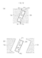
FIGS. 5 to 7 , description will be given of an example of the molding method of molding thefoam duct 200 of the present embodiment.FIG. 5 shows a state in which acylindrical foam parison 14 is extruded from anannular die 11.FIGS. 6 and7 show states of thefoam parison 14 viewed from theannular die 11 ofFIG. 5 . - First, as
FIG. 5 shows, various materials, for example, a resin prepared by adding a foaming agent to a polypropylene-based resin having an equilibrium compliance of 2.0 to 6.0 (10-3xPa-1) are melted and kneaded into foam resin. The foam resin is extruded from theannular die 11 of an extruding machine to form acylindrical foam parison 14. Thefoam parison 14 is placed between splitmetallic mold blocks foam parison 14 between the splitmetallic mold blocks FIGS. 5 and6(a) . - Next, the mold blocks 12a and 12b are moved to the side of the
foam parison 14 as shown inFIG. 6(b) such thatcavities foam parison 14. Portions of thefoam parison 14 atpositions cavities foam parison 14. Theseportions projections 204. - Thereafter, as shown in
FIG. 6(c) , the mold blocks 12a and 12b are driven to the clamping state and thefoam parison 14 is clamped between the mold blocks 12a and 12b. Both ends of thefoam parison 14 are nipped by pinch-offportions foam parison 14 in a space between thecavities 10 and 10b of the mold blocks 12a and 12b. - Next, in the clamping state of the mold blocks 12a and 12b, a blow-in needle and a blow-out needle are inserted in the
foam parison 14. Compressed gas such as air is blown from the blow-in needle into thefoam parison 14. The air passes through the inside of thefoam parison 14 and is blown out via the blow-out needle, to thereby conduct the blow molding at a predetermined blow pressure. As a result, as shown inFIG. 7(a) , thefoam parison 14 is pushed against wall surfaces of thecavities cavities - In the
foam parison 14 of the present embodiment, asFIG. 6(b) shows, the portions of thefoam parison 14 atpositions cavities foam parison 14, and have already made contact with thecavities FIG. 7(a) shows, the portions at thepositions cavities foam parison 14 not being brought into contact with thecavities FIG. 6(c) remain soft, and have a long distance to make contact with thecavities FIG. 7(a) shows, theprojection 204 is formed at thepositions foam parison 14 are first brought into contact with thecavities FIG. 6(b) . The portions not being brought into contact with thecavities FIG. 6(b) are extended, to form portions which are thinner than the portions in which theprojection 204 is formed. As a result, the thickness of the wall portion constituting the connectingportion 206 is greater in the portion in which theprojection 204 is formed than in the portion in which theprojection 204 is not formed. - When the blow molding is carried out at a predetermined blow pressure, it is possible to dispose a heat regulating unit to heat the compressed gas, which is supplied from the blow-in needle into the
foam parison 14, to a predetermined temperature. Since the compressed gas supplied into thefoam parison 14 is at a predetermined temperature, the foaming agent contained in thefoam parison 14 easily foams. The predetermined temperature is favorably set to a temperature suitable to make the foaming agent easily foam. - It is also possible to conduct the molding without disposing the heat regulating unit. That is, the compressed gas supplied into the
foam parison 14 is at a room temperature. Since it is not required to dispose the heat regulating unit to adjust the temperature of the compressed gas, thefoam duct 200 can be molded at a low cost. Since thefoam duct 200 is cooled after the blow molding and the blow molding is conducted at a room temperature, the period of time required to cool thefoam duct 200 after the blow molding is reduced. - In the present embodiment, while compressed gas is being supplied from the blow-in needle into the
foam parison 14, air is exhausted from thecavities foam parison 14 and thecavities foam parison 14 housed between thecavities foam parison 14 is higher than that outside the foam parison 14). Hence, thefoam parison 14 is pushed against the wall surfaces of thecavities cavities foam duct 200 includingprojection 204 in the duct inner surface. - In the molding process, it is not required to simultaneously conduct the process to blow compressed gas into the foam parison 1 and the process to produce a negative pressure outside the foam parison 1. These processes may be performed with an interval of time therebetween. Or, it is possible to conduct only one of these processes to carry out the molding in which the
foam parison 14 is pushed against the wall surfaces of thecavities cavities foam duct 200 includingprojection 204 in the duct inner surface. - Next, compressed gas such as air is supplied from the blow-in needle into the
foam parison 14. The air passes through thefoam parison 14 to be exhausted from the blow-out needle, to cool thefoam duct 200 at a predetermined blow pressure. - When cooling the
foam duct 200, the compressed gas supplied from the blow-in needle into thefoam parison 14 is set to a temperature ranging from 10°C to 30°C, preferably to a room temperature, e.g., 23°C. By setting the compressed gas to a room temperature, it is not required to dispose the heat regulating unit to adjust the temperature of the compressed gas; hence, thefoam duct 200 can be molded at a low cost. Further, when the heat regulating unit is disposed to set the compressed gas to a temperature lower than the room temperature, the period of time required to cool thefoam duct 200 is reduced. The cooling period of time favorably ranges from 30 seconds to 80 seconds although depending on the temperature of the compressed gas. - As a result, there is molded a
foam duct 200 includingprojections 204 in the duct inner surface. After thefoam duct 200 is molded, the mold blocks 12a and 12b are opened to take out thefoam duct 200 therefrom, and then undesired portions such as burrs are removed as shown inFIG. 7(b) . Resultantly, thefoam duct 200 shown inFIG. 1 is obtained. - As above, in the
foam duct 200 of the present embodiment, thecylindrical foam parison 14 is arranged between the mold blocks 12a and 12b as shown inFIG. 6(a) and thecavities foam parison 14, to harden theportions foam parison 14 first brought into contact with thecavities FIG. 6(b) . Next, asFIG. 6(c) shows, the mold blocks 12a and 12b are driven to the clamping state. In the clamping state of the mold blocks 12a and 12b, the blow-in and blow-out needles are inserted into thefoam parison 14 to carry out the blow molding at a predetermined blow pressure, to extend thefoam parison 14 according to the contours of thecavities FIG. 7(a) . As a result, theprojection 204 is formed in theportions cavities FIG. 6(b) . The portions not brought into contact with thecavities FIG. 6(b) are extended to form thinner portions. Resultantly, there is molded thefoam duct 200 includingprojections 204 in the duct inner surface as shown inFIG. 1 . - Since the
foam duct 200 of the present embodiment includes theprojections 204 in the duct inner surface as shown inFIG. 2 , it is possible to improve rigidity of thefoam duct 200. Also, asFIGS. 3 and 4 show, when anothermember 300 is inserted in an inner surface side of the connectingportion 206 to engage the inner surface side of the connectingportions 206 with an outer surface side of themember 300 for the connection therebetween, the outer surface side of themember 300 makes contact with theprojections 204, to thereby prevent the event in which thefoam duct 200 is easily removed from themember 300. Theprojections 204 include foam resin. Hence, when the outer surface side of themember 300 makes contact with theprojection 204 in the state shown inFIG. 2 , theprojections 204 deform according to the outer surface contour of themember 300, to hold themember 300 as shown inFIG. 4 . - In the molding method described above, it is also possible to conduct low-pressure molding in which a suction process is carried out for the
cavities foam parison 14 according to the contours of thecavities cavities FIG. 6(b) . - In the
foam duct 200 of the present embodiment, a gap exists between the inner surface of the connectingportion 206 and the outer surface of themember 300 as shown inFIGS. 3 and 4 . However, to remove the gap, it is also possible that for example, as shown inFIG. 8(a) , a packingmember 400 such as foam urethane is pasted around the outer circumferential surface of themember 300, and themember 300 around which the packingmember 400 is pasted is inserted in the inner surface side of thecylindrical portion 206 for the connection therebetween as shown inFIG. 8(b) . Hence, it possible to prevent occurrence of the gap between the outer surface of themember 300 and the inner surface of the connectingportion 206.FIG. 8 (c) shows an example of an X-X' cross-sectional configuration perpendicular to the hollow extending direction of the connectingportion 206 shown inFIG. 8(b) . In this regard, it is not necessarily required to paste the packingmember 400 onto themember 300 as shown inFIG. 8 . It is also possible the outer surface contour of themember 300 itself is designed to follow the inner surface contour of the connectingportion 206, to thereby prevent occurrence of the gap between the outer surface of themember 300 and the inner surface of the connectingportion 206. - Next, description will be given of a second embodiment.
- In the description of the configuration example of the
foam duct 200 according to the first embodiment, the connectingportion 206 includes no branch as shown inFIG. 1 . - In the configuration example of the
foam duct 200 in the second embodiment, the connectingportion 206 includes two or more branches as shown inFIG. 9 . Also in the situation of the configuration example shown inFIG. 9 ,projections 204 are formed in the connectingportion 206. As a result, it is possible to prevent the event in which thefoam duct 200 is easily removed from anothermember 300. Next, referring toFIGS. 9 to 13 , description will be given of thefoam duct 200 of the present embodiment. In the description below, an "inpane" duct will be employed as an example of thefoam duct 200. - Referring to
FIGS. 9 to 11 , description will be given of a configuration example of thefoam duct 200 of the present embodiment.FIG. 9 shows a configuration example of thefoam duct 200.FIG. 9(a) shows the side of afirst wall portion 201 of thefoam duct 200.FIG. 9(b) shows the side of asecond wall portions 202 of thefoam duct 200.FIG. 10 shows a configuration example of a connectingportion 206 of thefoam duct 200 shown inFIG. 9(a) .FIG. 10(a) is an external perspective view of the connectingportion 206.FIG. 10(b) shows an example of an X-X' cross-sectional configuration perpendicular to the hollow extending direction of the connectingportion 206.FIG. 11 shows a configuration example in a state in which anothermember 300 is connected to the connectingportion 206. - The
foam duct 200 of the present embodiment includes afirst wall portion 201 and asecond wall portion 202 which are welded onto each other via parting lines PL1 and PL2. - The
foam duct 200 includes ahollow portion 205 in the duct such that fluid such as air flows through thehollow portion 205. Thefoam duct 200 also includes a connectingportion 206 to connect to anothermember 300. The connectingportion 206 includes two or more branches. The opening of the connectingportion 206 in this embodiment has a rectangular contour to configure a female-type connecting portion 206 as shown inFIG. 11 such that an inner surface side of the connectingportion 206 engages with an outer surface side of themember 300 for the connection therebetween. Thefoam duct 200 include aprojection 204 in an inner surface side of the connectingportion 206 as shown inFIG. 10 . Thickness of the wall portion configuring the connectingportion 206 is larger in the portion in which theprojection 204 is formed than in the portion in which theprojection 204 is not formed. - The first and
second wall portions foam duct 200 have a mean thickness ranging from 2.0 mm to 3.0 mm. In the crosssectional contour of the connectingportion 206 shown inFIG. 10(b) , the difference in thickness between the portion in which theprojection 204 is not formed and the portion in which theprojection 204 is formed ranges from 0.5 mm to 1.0 mm. - The mean thickness is mean thickness calculated by use of thickness values measured at an equal interval of about 100 mm in the hollow extending direction of the
foam duct 200. The hollow extending direction is a direction in which thehollow portions 205 extends in thefoam duct 20 and is the direction in which fluid flows. The mean thickness on the side of thefirst wall portion 201 of thefoam duct 200 is mean thickness calculated by use of thickness values measured at 18 positions, i.e., positions 11 to 19 and 20 to 28 on the side of thefirst wall portion 201 of thefoam duct 200 shown inFIG. 9(a) . The mean thickness on the side of thesecond wall portion 202 is mean thickness calculated by use of thickness values measured at 16 positions, i.e., positions 31 to 38 and 39 to 46 on the side of thesecond wall portion 202 of thefoam duct 200 shown inFIG. 9(b) . The mean thickness of theoverall foam duct 200 is mean thickness calculated by use of the mean thickness on the side of thefirst wall portion 201 and the mean thickness on the side of thesecond wall portion 202. - In the crosssectional contour of the connecting
portions 206, the thickness takes the maximum value in the portion in which theprojection 204 is formed and the minimum value in the portion most apart from the line connecting the parting lines PL1 and PL2 to each other. AsFIG. 10(b) shows, the blow ratio of the connectingportion 206 is a ratio (B/A), taken in the crosssection perpendicular to the hollow extending direction, between length A of the straight line connecting parting lines PL1 and PL2 to each other and distance B from straight line A to an outer surface of the wall portion most apart therefrom. The blow ratio is 0.4 inFIG. 10(b) . - The
foam duct 200 of the present embodiment includes theprojection 204 on an inner surface side of the connectingportions 206. Hence, as shown inFIG. 11 , when anothermember 300 is inserted in the inner surface side of the connectingportion 206 to engage the inner surface side of the connectingportion 206 with an outer surface side of themember 300 for the connection therebetween, theprojection 204 makes contact with the outer surface side of themember 300. Further, since thefoam duct 200 includesprojection 204 in the vicinity of the parting lines PL1 and PL2, it is possible to more stably hold themember 300 inserted in the connectingportion 206 when compared with the first embodiment. Also, since theprojection 204 includes foam resin, when theprojection 204 makes contact with the outer surface side of themember 300 in the state shown inFIG. 10 , theprojection 204 deforms along the outer surface contour of themember 300 to stably hold themember 300 as shown inFIG. 11 . It is hence possible to prevent the event in which thefoam duct 200 is easily removed from themember 300. Incidentally, like thefoam duct 200 of the first embodiment, thefoam duct 200 of the present embodiment includes aprojection 204 not only in the connectingportion 206 of the opening edge portion, but also in the duct inner surface other than the opening edge portion, to thereby improve rigidity of thefoam duct 200. In this situation, theprojection 204 is favorably disposed in a continuous fashion along the channel direction (hollow extending direction) of the fluid flowing through the inside of thefoam duct 200. This further prevents deflection of thefoam duct 200 and occurrence of vibration in thefoam duct 200. - Next, referring to
FIGS. 5 ,12 , and13 , description will be given of an example of the molding method of molding thefoam duct 200 of the present embodiment. - As
FIG. 5 shows, various materials, for example, a resin prepared by adding a foaming agent to a polypropylene-based resin having an equilibrium compliance of 2.0 to 6.0 (10-3xPa-1) are melted and kneaded into foam resin. The foam resin is extruded from theannular die 11 of an extruding machine to form acylindrical foam parison 14. The foam parison is arranged between splitmetallic mold blocks foam parison 14 between the splitmetallic mold blocks FIGS. 5 and12(a) . - Next, the mold blocks 12a and 12b are moved to the side of the
foam parison 14 as shown inFIG. 12(b) such thatcavities foam parison 14, to form sealedspaces foam parison 14 and thecavities foam parison 14 atpositions cavities foam parison 14. Theprojections 204 are formed by use of theportions - Next, the suction process is performed via the mold blocks 12a and 12b for the sealed
spaces foam parison 14 is pushed against thecavities foam parison 14 in the contour along thecavities FIG. 12(c) . In a space formed by the mold blocks 12a and 12b of the present embodiment, a vacuum suction chamber, not shown, is disposed to be connected via suction holes to thecavities foam parison 14 is adsorbed toward thecavities foam parison 14 in the contour along outer surfaces of thecavities - In the
foam parison 14 of the present embodiment, asFIG. 12(b) shows, the portions of thefoam parison 14 atpositions cavities foam parison 14, and have already made contact with thecavities FIG. 12(c) shows, the portions at thepositions cavities foam parison 14 not being brought into contact with thecavities FIG. 12(b) remain soft, and have a long distance to make contact with thecavities FIG. 12(c) shows,projections 204 are formed at thepositions foam parison 14 are first brought into contact with thecavities FIG. 12(b) . The portions not being brought into contact with thecavities FIG. 12(b) are extended, to form portions which are thinner than the portions in which theprojections 204 are formed. - Next, as
FIG. 13(a) shows, the mold blocks 12a and 12b are driven to the clamping state and thefoam parison 14 is clamped between the mold blocks 12a and 12b. Both ends of thefoam parison 14 are nipped by the mold blocks 12a and 12b, to accommodate thefoam parison 14 in a space between thecavities 10 and 10b of the mold blocks 12a and 12b. Further, peripheral portions of theform parison 14 are welded onto each other, to thereby form the parting lines PL1 and PL2. - After the
foam duct 200 is molded, the mold blocks 12a and 12b are opened to take out thefoam duct 200 therefrom, and then undesired portions such as burrs are removed as shown inFIG. 13(b) . As a result, thefoam duct 200 shown inFIGS. 9 and10 is obtained. <Operation and effect offoam duct 200 of present embodiment> - As described above, in the
foam duct 200 of the present embodiment, thecylindrical foam parison 14 is arranged between the mold blocks 12a and 12b as shown inFIG. 12(a) , and thecavities foam parison 14, to harden theportions foam parison 14 first brought into contact with thecavities FIG. 12(b) . AsFIG. 12(c) shows, thefoam parison 14 is shaped into the contours of thecavities foam parison 14 according to the contours of thecavities projection 204 is formed in theportions cavities FIG. 12(b) , and the portions not brought into contact with thecavities FIG. 12(b) are extended to form thinner portions. Next, by setting the mold blocks 12a and 12b to the clamping state, peripheral portions of theform parison 14 are welded to each other, to thereby form the parting lines PL1 and PL2. Resultantly, there is molded thefoam duct 200 includingprojection 204 in the duct inner surfaces as shown inFIGS. 9 and10 . - Since the
foam duct 200 of the present embodiment includes theprojections 204 in the duct inner surfaces as shown inFIG. 10 , it is possible to improve rigidity of thefoam duct 200. Further, asFIG. 11 shows, when anothermember 300 is inserted in an inner surface side of the connectingportion 206 to engage the inner surface side of the connectingportion 206 with an outer surface side of themember 300 for the connection therebetween, the outer surface side of themember 300 makes contact with theprojections 204, to thereby prevent the event in which thefoam duct 200 is easily removed from themember 300. Theprojections 204 include foam resin. Hence, when the outer surface side of themember 300 makes contact with theprojection 204 in the state shown inFIG. 10 , theprojection 204 deform according to the outer surface contours of themember 300, to hold themember 300 as shown inFIG. 11 . - It is also possible in the present embodiment that a packing
member 400 such as foam urethane is pasted around the outer circumferential surface of themember 300, and themember 300 around which the packingmember 400 is pasted is inserted in the inner surface side of thecylindrical portion 206. Further, it is possible that the outer surface contour of themember 300 itself is designed to follow the inner surface contour of the connectingportions 206, to insert themember 300 into the inner surface of the connectingportion 206. - The embodiments described above are favorable embodiments of the present invention. The present invention is not limited to these embodiments, but various changes in form and details may be made therein without departing from the spirit and scope of the present invention as defined claims.
- For example, in conjunction with the embodiments, description has been given of an example in which the
foam duct 200 includes aprojection 204 in the duct inner surface. However, thefoam duct 200 shown inFIGS. 9 and10 can be molded by using two foam resin sheets (each having the contour of a sheet) in place of thecylindrical foam parison 14. When the foam resin sheets are employed, it is possible to adjust sheet thickness of each foam resin sheet. Hence, the thickness may differ between the first andsecond wall portions projection 204 may also differ between the first andsecond wall portions hollow portion 205 of thefoam duct 200. - The contours of the
cavities foam duct 200 are not limited to those described above. Thecavities projection 204 and thecavities foam parison 14 or part of the foam resin sheet.
Claims (10)
- A foam duct element comprising foam resin, and including a cylindrical portion having an external contour of a polygonal shape and having an inner surface projection, wherein the thickness of wall portions of the cylindrical portion is larger in a region with the projection, than in a region without the projection.
- A foam duct element in accordance with Claim 1, wherein the cylindrical portion includes opening edge portions.
- A foam duct element in accordance with Claim 1 or 2, wherein:the foam duct has a three-dimensional contour profile; andthe projection is formed in a continuous fashion in a channel direction of fluid flowing through the duct.
- A foam duct element in accordance with any one or more of Claim 1 to 3, wherein the projection is formed in an inner surface of a wall portion also constituting an external contour of the cylindrical portion in a longitudinal direction.
- A foam duct element in accordance with any one or more of Claims 1 to 4, wherein difference in thickness between the portion with the projection, and the portion without the projection is from 0.5mm to 1mm.
- A foam duct element in accordance with any one or more of Claims 1 to 5, wherein the expansion ratio is 2.0 or more and the maximum blow ratio is 0.2 or more.
- A foam duct element in accordance with any one or more of Claims 1 to 6, and comprising a foam duct connecting portion.
- A foam duct element in accordance with any one or more of Claims 1 to 7, and in accordance with the any one or more of the embodiments listed in the accompanying description.
- A method of forming a foam duct element, including the steps of forming a cylindrical portion with external contour of a polygonal shape and with an inner surface projection such that the wall thickness in the region of the projection is greater than elsewhere.
- A method as claimed in Claim 9 and according to any one or more of the embodiments listed in the accompanying description.
Applications Claiming Priority (1)
| Application Number | Priority Date | Filing Date | Title |
|---|---|---|---|
| JP2012042294A JP5982870B2 (en) | 2012-02-28 | 2012-02-28 | Foam duct |
Publications (2)
| Publication Number | Publication Date |
|---|---|
| EP2633967A1 true EP2633967A1 (en) | 2013-09-04 |
| EP2633967B1 EP2633967B1 (en) | 2020-04-01 |
Family
ID=47748446
Family Applications (1)
| Application Number | Title | Priority Date | Filing Date |
|---|---|---|---|
| EP13155529.4A Active EP2633967B1 (en) | 2012-02-28 | 2013-02-15 | Foam duct |
Country Status (5)
| Country | Link |
|---|---|
| US (1) | US8795802B2 (en) |
| EP (1) | EP2633967B1 (en) |
| JP (1) | JP5982870B2 (en) |
| KR (1) | KR101489053B1 (en) |
| CN (1) | CN103292052B (en) |
Cited By (2)
| Publication number | Priority date | Publication date | Assignee | Title |
|---|---|---|---|---|
| US10590252B2 (en) | 2014-12-22 | 2020-03-17 | Kyoraku Co., Ltd. | Foaming assistant material and foam-molding method |
| EP4538072A3 (en) * | 2014-05-23 | 2025-09-10 | Kyoraku Co., Ltd. | Molded foam |
Families Citing this family (6)
| Publication number | Priority date | Publication date | Assignee | Title |
|---|---|---|---|---|
| US9038672B2 (en) * | 2010-12-02 | 2015-05-26 | Salflex Polymers Limited | Hollow article of variable wall structure density |
| JP5982870B2 (en) * | 2012-02-28 | 2016-08-31 | キョーラク株式会社 | Foam duct |
| CA2902027A1 (en) * | 2013-02-20 | 2014-08-20 | Crane Engineering, Inc. | Self-obstructing flammable fluid carrying conduit |
| JP6429009B2 (en) * | 2014-10-27 | 2018-11-28 | キョーラク株式会社 | Blow molding method and blow molding apparatus |
| JP6795761B2 (en) * | 2016-10-27 | 2020-12-02 | キョーラク株式会社 | Structure |
| TWD213271S (en) * | 2020-11-05 | 2021-08-11 | 大陸商亞浩電子五金塑膠(惠州)有限公司 | Heat pipe |
Citations (6)
| Publication number | Priority date | Publication date | Assignee | Title |
|---|---|---|---|---|
| GB1088133A (en) * | 1965-05-07 | 1967-10-25 | Versatile Fittings W H S Ltd | Improvements relating to hollow tubes |
| US4615411A (en) * | 1982-05-27 | 1986-10-07 | Dynamit Nobel Ag | Sound-insulated flow duct and process for the manufacture thereof |
| DE3704827A1 (en) * | 1987-02-16 | 1988-08-25 | Marquet & Cie Noel | Universal insulating half-shells which are bent at right angles and are intended for right-angled pipe bends with different bend radii and bend ends |
| FR2776750A1 (en) * | 1998-03-26 | 1999-10-01 | Giat Ind Sa | POLYEDRIC TANK FOR CONTAINING PRESSURIZED FLUIDS |
| JP2002156152A (en) * | 2000-11-17 | 2002-05-31 | Sanpo Kobunshi Kk | Duct |
| EP1236835A1 (en) * | 2001-02-16 | 2002-09-04 | Stekox GmbH | Injection tube for sealing building joints |
Family Cites Families (8)
| Publication number | Priority date | Publication date | Assignee | Title |
|---|---|---|---|---|
| US2226523A (en) * | 1940-01-06 | 1940-12-24 | Wm Burchenal | Conduit construction |
| DE3132865A1 (en) * | 1981-08-20 | 1983-03-24 | Artus 5060 Bergisch Gladbach Feist | PIPE TO BE LAYED IN THE SCREED OF A FLOOR AND IN FINISHED ELEMENTS |
| FR2805592B1 (en) * | 2000-02-25 | 2002-05-03 | Nobel Plastiques | FUEL RESISTANT FUEL TRANSPORT TUBING |
| JP5025549B2 (en) * | 2008-03-31 | 2012-09-12 | キョーラク株式会社 | Foam blow molded article and method for producing the same |
| JP2010236838A (en) | 2009-03-31 | 2010-10-21 | Furukawa Electric Co Ltd:The | Air conditioning duct connection structure |
| JP5803086B2 (en) * | 2009-10-31 | 2015-11-04 | キョーラク株式会社 | Foam molded body molding method and foam molded body |
| JP5709390B2 (en) | 2010-03-19 | 2015-04-30 | 株式会社イノアックコーポレーション | Automotive duct |
| JP5982870B2 (en) * | 2012-02-28 | 2016-08-31 | キョーラク株式会社 | Foam duct |
-
2012
- 2012-02-28 JP JP2012042294A patent/JP5982870B2/en active Active
-
2013
- 2013-02-07 US US13/761,262 patent/US8795802B2/en active Active
- 2013-02-15 EP EP13155529.4A patent/EP2633967B1/en active Active
- 2013-02-22 KR KR20130019007A patent/KR101489053B1/en active Active
- 2013-02-27 CN CN201310062260.7A patent/CN103292052B/en active Active
Patent Citations (6)
| Publication number | Priority date | Publication date | Assignee | Title |
|---|---|---|---|---|
| GB1088133A (en) * | 1965-05-07 | 1967-10-25 | Versatile Fittings W H S Ltd | Improvements relating to hollow tubes |
| US4615411A (en) * | 1982-05-27 | 1986-10-07 | Dynamit Nobel Ag | Sound-insulated flow duct and process for the manufacture thereof |
| DE3704827A1 (en) * | 1987-02-16 | 1988-08-25 | Marquet & Cie Noel | Universal insulating half-shells which are bent at right angles and are intended for right-angled pipe bends with different bend radii and bend ends |
| FR2776750A1 (en) * | 1998-03-26 | 1999-10-01 | Giat Ind Sa | POLYEDRIC TANK FOR CONTAINING PRESSURIZED FLUIDS |
| JP2002156152A (en) * | 2000-11-17 | 2002-05-31 | Sanpo Kobunshi Kk | Duct |
| EP1236835A1 (en) * | 2001-02-16 | 2002-09-04 | Stekox GmbH | Injection tube for sealing building joints |
Cited By (3)
| Publication number | Priority date | Publication date | Assignee | Title |
|---|---|---|---|---|
| EP4538072A3 (en) * | 2014-05-23 | 2025-09-10 | Kyoraku Co., Ltd. | Molded foam |
| US10590252B2 (en) | 2014-12-22 | 2020-03-17 | Kyoraku Co., Ltd. | Foaming assistant material and foam-molding method |
| EP3239220B1 (en) * | 2014-12-22 | 2020-10-28 | Kyoraku Co., Ltd. | Foamed auxiliary material and foamed molding method |
Also Published As
| Publication number | Publication date |
|---|---|
| JP2013177076A (en) | 2013-09-09 |
| US20130224414A1 (en) | 2013-08-29 |
| US8795802B2 (en) | 2014-08-05 |
| CN103292052A (en) | 2013-09-11 |
| JP5982870B2 (en) | 2016-08-31 |
| EP2633967B1 (en) | 2020-04-01 |
| KR20130098911A (en) | 2013-09-05 |
| CN103292052B (en) | 2016-04-27 |
| KR101489053B1 (en) | 2015-02-02 |
Similar Documents
| Publication | Publication Date | Title |
|---|---|---|
| EP2633967B1 (en) | Foam duct | |
| JP7060782B2 (en) | Manufacturing method of foam molded product | |
| EP2633966B1 (en) | Foam duct | |
| JP6667090B2 (en) | Tubular body | |
| JP6777853B2 (en) | Manufacturing method of molded products | |
| JP6485052B2 (en) | Resin panel | |
| KR102411688B1 (en) | Molded article and its manufacturing method | |
| JP7299494B2 (en) | Foam molded article and method for producing the same | |
| JP6657549B2 (en) | Manufacturing method of double structure duct | |
| JP6795761B2 (en) | Structure | |
| JP6016073B2 (en) | Laminated panel | |
| JP7280502B2 (en) | Duct manufacturing method | |
| JP6923797B2 (en) | Structure and its manufacturing method | |
| JP6202603B2 (en) | Air conditioning duct | |
| JP2005193726A (en) | Foam duct | |
| JP6194083B2 (en) | Foam duct | |
| JP6217364B2 (en) | duct | |
| JP2022104021A (en) | Welding jig and molding method of molded body using jig | |
| WO2018097237A1 (en) | Method for manufacturing vibration-damping member and method for manufacturing structural body | |
| JP2013099883A (en) | Method of molding foam molded article and the foam molded article | |
| JP2018179357A (en) | Molded article and method for manufacturing the same | |
| JP2013099882A (en) | Method for molding molded foam product and molded foam product | |
| JP2019060523A (en) | Foamed duct and method of molding the same | |
| JP2008049757A (en) | Instrument panel air duct structure |
Legal Events
| Date | Code | Title | Description |
|---|---|---|---|
| PUAI | Public reference made under article 153(3) epc to a published international application that has entered the european phase |
Free format text: ORIGINAL CODE: 0009012 |
|
| 17P | Request for examination filed |
Effective date: 20130215 |
|
| AK | Designated contracting states |
Kind code of ref document: A1 Designated state(s): AL AT BE BG CH CY CZ DE DK EE ES FI FR GB GR HR HU IE IS IT LI LT LU LV MC MK MT NL NO PL PT RO RS SE SI SK SM TR |
|
| AX | Request for extension of the european patent |
Extension state: BA ME |
|
| 17Q | First examination report despatched |
Effective date: 20160623 |
|
| STAA | Information on the status of an ep patent application or granted ep patent |
Free format text: STATUS: EXAMINATION IS IN PROGRESS |
|
| REG | Reference to a national code |
Ref country code: DE Ref legal event code: R079 Ref document number: 602013067359 Country of ref document: DE Free format text: PREVIOUS MAIN CLASS: B29C0044120000 Ipc: B29L0023000000 |
|
| RIC1 | Information provided on ipc code assigned before grant |
Ipc: F16L 9/00 20060101ALI20190731BHEP Ipc: F16L 59/14 20060101ALI20190731BHEP Ipc: B29L 23/00 20060101AFI20190731BHEP Ipc: B29C 44/12 20060101ALI20190731BHEP Ipc: B32B 1/08 20060101ALI20190731BHEP |
|
| GRAP | Despatch of communication of intention to grant a patent |
Free format text: ORIGINAL CODE: EPIDOSNIGR1 |
|
| STAA | Information on the status of an ep patent application or granted ep patent |
Free format text: STATUS: GRANT OF PATENT IS INTENDED |
|
| INTG | Intention to grant announced |
Effective date: 20190916 |
|
| GRAS | Grant fee paid |
Free format text: ORIGINAL CODE: EPIDOSNIGR3 |
|
| GRAA | (expected) grant |
Free format text: ORIGINAL CODE: 0009210 |
|
| STAA | Information on the status of an ep patent application or granted ep patent |
Free format text: STATUS: THE PATENT HAS BEEN GRANTED |
|
| AK | Designated contracting states |
Kind code of ref document: B1 Designated state(s): AL AT BE BG CH CY CZ DE DK EE ES FI FR GB GR HR HU IE IS IT LI LT LU LV MC MK MT NL NO PL PT RO RS SE SI SK SM TR |
|
| REG | Reference to a national code |
Ref country code: GB Ref legal event code: FG4D |
|
| REG | Reference to a national code |
Ref country code: AT Ref legal event code: REF Ref document number: 1250838 Country of ref document: AT Kind code of ref document: T Effective date: 20200415 Ref country code: CH Ref legal event code: EP |
|
| REG | Reference to a national code |
Ref country code: DE Ref legal event code: R096 Ref document number: 602013067359 Country of ref document: DE |
|
| REG | Reference to a national code |
Ref country code: IE Ref legal event code: FG4D |
|
| PG25 | Lapsed in a contracting state [announced via postgrant information from national office to epo] |
Ref country code: BG Free format text: LAPSE BECAUSE OF FAILURE TO SUBMIT A TRANSLATION OF THE DESCRIPTION OR TO PAY THE FEE WITHIN THE PRESCRIBED TIME-LIMIT Effective date: 20200701 |
|
| REG | Reference to a national code |
Ref country code: NL Ref legal event code: MP Effective date: 20200401 |
|
| REG | Reference to a national code |
Ref country code: LT Ref legal event code: MG4D |
|
| PG25 | Lapsed in a contracting state [announced via postgrant information from national office to epo] |
Ref country code: GR Free format text: LAPSE BECAUSE OF FAILURE TO SUBMIT A TRANSLATION OF THE DESCRIPTION OR TO PAY THE FEE WITHIN THE PRESCRIBED TIME-LIMIT Effective date: 20200702 Ref country code: IS Free format text: LAPSE BECAUSE OF FAILURE TO SUBMIT A TRANSLATION OF THE DESCRIPTION OR TO PAY THE FEE WITHIN THE PRESCRIBED TIME-LIMIT Effective date: 20200801 Ref country code: SE Free format text: LAPSE BECAUSE OF FAILURE TO SUBMIT A TRANSLATION OF THE DESCRIPTION OR TO PAY THE FEE WITHIN THE PRESCRIBED TIME-LIMIT Effective date: 20200401 Ref country code: NL Free format text: LAPSE BECAUSE OF FAILURE TO SUBMIT A TRANSLATION OF THE DESCRIPTION OR TO PAY THE FEE WITHIN THE PRESCRIBED TIME-LIMIT Effective date: 20200401 Ref country code: LT Free format text: LAPSE BECAUSE OF FAILURE TO SUBMIT A TRANSLATION OF THE DESCRIPTION OR TO PAY THE FEE WITHIN THE PRESCRIBED TIME-LIMIT Effective date: 20200401 Ref country code: FI Free format text: LAPSE BECAUSE OF FAILURE TO SUBMIT A TRANSLATION OF THE DESCRIPTION OR TO PAY THE FEE WITHIN THE PRESCRIBED TIME-LIMIT Effective date: 20200401 Ref country code: NO Free format text: LAPSE BECAUSE OF FAILURE TO SUBMIT A TRANSLATION OF THE DESCRIPTION OR TO PAY THE FEE WITHIN THE PRESCRIBED TIME-LIMIT Effective date: 20200701 Ref country code: PT Free format text: LAPSE BECAUSE OF FAILURE TO SUBMIT A TRANSLATION OF THE DESCRIPTION OR TO PAY THE FEE WITHIN THE PRESCRIBED TIME-LIMIT Effective date: 20200817 Ref country code: CZ Free format text: LAPSE BECAUSE OF FAILURE TO SUBMIT A TRANSLATION OF THE DESCRIPTION OR TO PAY THE FEE WITHIN THE PRESCRIBED TIME-LIMIT Effective date: 20200401 |
|
| REG | Reference to a national code |
Ref country code: AT Ref legal event code: MK05 Ref document number: 1250838 Country of ref document: AT Kind code of ref document: T Effective date: 20200401 |
|
| PG25 | Lapsed in a contracting state [announced via postgrant information from national office to epo] |
Ref country code: HR Free format text: LAPSE BECAUSE OF FAILURE TO SUBMIT A TRANSLATION OF THE DESCRIPTION OR TO PAY THE FEE WITHIN THE PRESCRIBED TIME-LIMIT Effective date: 20200401 Ref country code: LV Free format text: LAPSE BECAUSE OF FAILURE TO SUBMIT A TRANSLATION OF THE DESCRIPTION OR TO PAY THE FEE WITHIN THE PRESCRIBED TIME-LIMIT Effective date: 20200401 Ref country code: RS Free format text: LAPSE BECAUSE OF FAILURE TO SUBMIT A TRANSLATION OF THE DESCRIPTION OR TO PAY THE FEE WITHIN THE PRESCRIBED TIME-LIMIT Effective date: 20200401 |
|
| PG25 | Lapsed in a contracting state [announced via postgrant information from national office to epo] |
Ref country code: AL Free format text: LAPSE BECAUSE OF FAILURE TO SUBMIT A TRANSLATION OF THE DESCRIPTION OR TO PAY THE FEE WITHIN THE PRESCRIBED TIME-LIMIT Effective date: 20200401 |
|
| REG | Reference to a national code |
Ref country code: DE Ref legal event code: R097 Ref document number: 602013067359 Country of ref document: DE |
|
| PG25 | Lapsed in a contracting state [announced via postgrant information from national office to epo] |
Ref country code: ES Free format text: LAPSE BECAUSE OF FAILURE TO SUBMIT A TRANSLATION OF THE DESCRIPTION OR TO PAY THE FEE WITHIN THE PRESCRIBED TIME-LIMIT Effective date: 20200401 Ref country code: IT Free format text: LAPSE BECAUSE OF FAILURE TO SUBMIT A TRANSLATION OF THE DESCRIPTION OR TO PAY THE FEE WITHIN THE PRESCRIBED TIME-LIMIT Effective date: 20200401 Ref country code: AT Free format text: LAPSE BECAUSE OF FAILURE TO SUBMIT A TRANSLATION OF THE DESCRIPTION OR TO PAY THE FEE WITHIN THE PRESCRIBED TIME-LIMIT Effective date: 20200401 Ref country code: RO Free format text: LAPSE BECAUSE OF FAILURE TO SUBMIT A TRANSLATION OF THE DESCRIPTION OR TO PAY THE FEE WITHIN THE PRESCRIBED TIME-LIMIT Effective date: 20200401 Ref country code: DK Free format text: LAPSE BECAUSE OF FAILURE TO SUBMIT A TRANSLATION OF THE DESCRIPTION OR TO PAY THE FEE WITHIN THE PRESCRIBED TIME-LIMIT Effective date: 20200401 Ref country code: EE Free format text: LAPSE BECAUSE OF FAILURE TO SUBMIT A TRANSLATION OF THE DESCRIPTION OR TO PAY THE FEE WITHIN THE PRESCRIBED TIME-LIMIT Effective date: 20200401 Ref country code: SM Free format text: LAPSE BECAUSE OF FAILURE TO SUBMIT A TRANSLATION OF THE DESCRIPTION OR TO PAY THE FEE WITHIN THE PRESCRIBED TIME-LIMIT Effective date: 20200401 |
|
| PLBE | No opposition filed within time limit |
Free format text: ORIGINAL CODE: 0009261 |
|
| STAA | Information on the status of an ep patent application or granted ep patent |
Free format text: STATUS: NO OPPOSITION FILED WITHIN TIME LIMIT |
|
| PG25 | Lapsed in a contracting state [announced via postgrant information from national office to epo] |
Ref country code: SK Free format text: LAPSE BECAUSE OF FAILURE TO SUBMIT A TRANSLATION OF THE DESCRIPTION OR TO PAY THE FEE WITHIN THE PRESCRIBED TIME-LIMIT Effective date: 20200401 Ref country code: PL Free format text: LAPSE BECAUSE OF FAILURE TO SUBMIT A TRANSLATION OF THE DESCRIPTION OR TO PAY THE FEE WITHIN THE PRESCRIBED TIME-LIMIT Effective date: 20200401 |
|
| 26N | No opposition filed |
Effective date: 20210112 |
|
| PG25 | Lapsed in a contracting state [announced via postgrant information from national office to epo] |
Ref country code: SI Free format text: LAPSE BECAUSE OF FAILURE TO SUBMIT A TRANSLATION OF THE DESCRIPTION OR TO PAY THE FEE WITHIN THE PRESCRIBED TIME-LIMIT Effective date: 20200401 |
|
| PG25 | Lapsed in a contracting state [announced via postgrant information from national office to epo] |
Ref country code: MC Free format text: LAPSE BECAUSE OF FAILURE TO SUBMIT A TRANSLATION OF THE DESCRIPTION OR TO PAY THE FEE WITHIN THE PRESCRIBED TIME-LIMIT Effective date: 20200401 |
|
| REG | Reference to a national code |
Ref country code: BE Ref legal event code: MM Effective date: 20210228 |
|
| PG25 | Lapsed in a contracting state [announced via postgrant information from national office to epo] |
Ref country code: CH Free format text: LAPSE BECAUSE OF NON-PAYMENT OF DUE FEES Effective date: 20210228 Ref country code: LI Free format text: LAPSE BECAUSE OF NON-PAYMENT OF DUE FEES Effective date: 20210228 Ref country code: LU Free format text: LAPSE BECAUSE OF NON-PAYMENT OF DUE FEES Effective date: 20210215 |
|
| PG25 | Lapsed in a contracting state [announced via postgrant information from national office to epo] |
Ref country code: IE Free format text: LAPSE BECAUSE OF NON-PAYMENT OF DUE FEES Effective date: 20210215 |
|
| PG25 | Lapsed in a contracting state [announced via postgrant information from national office to epo] |
Ref country code: BE Free format text: LAPSE BECAUSE OF NON-PAYMENT OF DUE FEES Effective date: 20210228 |
|
| PG25 | Lapsed in a contracting state [announced via postgrant information from national office to epo] |
Ref country code: HU Free format text: LAPSE BECAUSE OF FAILURE TO SUBMIT A TRANSLATION OF THE DESCRIPTION OR TO PAY THE FEE WITHIN THE PRESCRIBED TIME-LIMIT; INVALID AB INITIO Effective date: 20130215 |
|
| PG25 | Lapsed in a contracting state [announced via postgrant information from national office to epo] |
Ref country code: CY Free format text: LAPSE BECAUSE OF FAILURE TO SUBMIT A TRANSLATION OF THE DESCRIPTION OR TO PAY THE FEE WITHIN THE PRESCRIBED TIME-LIMIT Effective date: 20200401 |
|
| PG25 | Lapsed in a contracting state [announced via postgrant information from national office to epo] |
Ref country code: MK Free format text: LAPSE BECAUSE OF FAILURE TO SUBMIT A TRANSLATION OF THE DESCRIPTION OR TO PAY THE FEE WITHIN THE PRESCRIBED TIME-LIMIT Effective date: 20200401 |
|
| PGFP | Annual fee paid to national office [announced via postgrant information from national office to epo] |
Ref country code: GB Payment date: 20240219 Year of fee payment: 12 |
|
| PGFP | Annual fee paid to national office [announced via postgrant information from national office to epo] |
Ref country code: FR Payment date: 20240221 Year of fee payment: 12 |
|
| PG25 | Lapsed in a contracting state [announced via postgrant information from national office to epo] |
Ref country code: MT Free format text: LAPSE BECAUSE OF FAILURE TO SUBMIT A TRANSLATION OF THE DESCRIPTION OR TO PAY THE FEE WITHIN THE PRESCRIBED TIME-LIMIT Effective date: 20200401 |
|
| GBPC | Gb: european patent ceased through non-payment of renewal fee |
Effective date: 20250215 |
|
| PG25 | Lapsed in a contracting state [announced via postgrant information from national office to epo] |
Ref country code: TR Free format text: LAPSE BECAUSE OF FAILURE TO SUBMIT A TRANSLATION OF THE DESCRIPTION OR TO PAY THE FEE WITHIN THE PRESCRIBED TIME-LIMIT Effective date: 20200401 |
|
| PG25 | Lapsed in a contracting state [announced via postgrant information from national office to epo] |
Ref country code: GB Free format text: LAPSE BECAUSE OF NON-PAYMENT OF DUE FEES Effective date: 20250215 |
|
| PG25 | Lapsed in a contracting state [announced via postgrant information from national office to epo] |
Ref country code: FR Free format text: LAPSE BECAUSE OF NON-PAYMENT OF DUE FEES Effective date: 20250228 |
|
| PGFP | Annual fee paid to national office [announced via postgrant information from national office to epo] |
Ref country code: DE Payment date: 20260218 Year of fee payment: 14 |