EP2632817B1 - Behälter mit zerbrechlicher geräteschnittstelle - Google Patents
Behälter mit zerbrechlicher geräteschnittstelle Download PDFInfo
- Publication number
- EP2632817B1 EP2632817B1 EP11776499.3A EP11776499A EP2632817B1 EP 2632817 B1 EP2632817 B1 EP 2632817B1 EP 11776499 A EP11776499 A EP 11776499A EP 2632817 B1 EP2632817 B1 EP 2632817B1
- Authority
- EP
- European Patent Office
- Prior art keywords
- cap
- valve
- bottle
- device interface
- liquid
- Prior art date
- Legal status (The legal status is an assumption and is not a legal conclusion. Google has not performed a legal analysis and makes no representation as to the accuracy of the status listed.)
- Not-in-force
Links
Images


Classifications
-
- B—PERFORMING OPERATIONS; TRANSPORTING
- B65—CONVEYING; PACKING; STORING; HANDLING THIN OR FILAMENTARY MATERIAL
- B65D—CONTAINERS FOR STORAGE OR TRANSPORT OF ARTICLES OR MATERIALS, e.g. BAGS, BARRELS, BOTTLES, BOXES, CANS, CARTONS, CRATES, DRUMS, JARS, TANKS, HOPPERS, FORWARDING CONTAINERS; ACCESSORIES, CLOSURES, OR FITTINGS THEREFOR; PACKAGING ELEMENTS; PACKAGES
- B65D47/00—Closures with filling and discharging, or with discharging, devices
- B65D47/04—Closures with discharging devices other than pumps
- B65D47/20—Closures with discharging devices other than pumps comprising hand-operated members for controlling discharge
- B65D47/24—Closures with discharging devices other than pumps comprising hand-operated members for controlling discharge with poppet valves or lift valves, i.e. valves opening or closing a passageway by a relative motion substantially perpendicular to the plane of the seat
- B65D47/248—Closures with discharging devices other than pumps comprising hand-operated members for controlling discharge with poppet valves or lift valves, i.e. valves opening or closing a passageway by a relative motion substantially perpendicular to the plane of the seat the valve being opened or closed by imparting a motion to the valve stem
-
- B—PERFORMING OPERATIONS; TRANSPORTING
- B65—CONVEYING; PACKING; STORING; HANDLING THIN OR FILAMENTARY MATERIAL
- B65D—CONTAINERS FOR STORAGE OR TRANSPORT OF ARTICLES OR MATERIALS, e.g. BAGS, BARRELS, BOTTLES, BOXES, CANS, CARTONS, CRATES, DRUMS, JARS, TANKS, HOPPERS, FORWARDING CONTAINERS; ACCESSORIES, CLOSURES, OR FITTINGS THEREFOR; PACKAGING ELEMENTS; PACKAGES
- B65D51/00—Closures not otherwise provided for
- B65D51/18—Arrangements of closures with protective outer cap-like covers or of two or more co-operating closures
- B65D51/20—Caps, lids, or covers co-operating with an inner closure arranged to be opened by piercing, cutting, or tearing
-
- A—HUMAN NECESSITIES
- A47—FURNITURE; DOMESTIC ARTICLES OR APPLIANCES; COFFEE MILLS; SPICE MILLS; SUCTION CLEANERS IN GENERAL
- A47K—SANITARY EQUIPMENT; ACCESSORIES THEREFOR, e.g. TOILET ACCESSORIES
- A47K5/00—Holders or dispensers for soap, toothpaste or the like
- A47K5/06—Dispensers for soap
- A47K5/12—Dispensers for soap for liquid or pasty soap
- A47K5/1202—Dispensers for soap for liquid or pasty soap dispensing dosed volume
-
- A—HUMAN NECESSITIES
- A47—FURNITURE; DOMESTIC ARTICLES OR APPLIANCES; COFFEE MILLS; SPICE MILLS; SUCTION CLEANERS IN GENERAL
- A47K—SANITARY EQUIPMENT; ACCESSORIES THEREFOR, e.g. TOILET ACCESSORIES
- A47K5/00—Holders or dispensers for soap, toothpaste or the like
- A47K5/06—Dispensers for soap
- A47K5/12—Dispensers for soap for liquid or pasty soap
- A47K5/13—Dispensers for soap for liquid or pasty soap of invertible type
-
- B—PERFORMING OPERATIONS; TRANSPORTING
- B23—MACHINE TOOLS; METAL-WORKING NOT OTHERWISE PROVIDED FOR
- B23P—METAL-WORKING NOT OTHERWISE PROVIDED FOR; COMBINED OPERATIONS; UNIVERSAL MACHINE TOOLS
- B23P19/00—Machines for simply fitting together or separating metal parts or objects, or metal and non-metal parts, whether or not involving some deformation; Tools or devices therefor so far as not provided for in other classes
-
- B—PERFORMING OPERATIONS; TRANSPORTING
- B65—CONVEYING; PACKING; STORING; HANDLING THIN OR FILAMENTARY MATERIAL
- B65D—CONTAINERS FOR STORAGE OR TRANSPORT OF ARTICLES OR MATERIALS, e.g. BAGS, BARRELS, BOTTLES, BOXES, CANS, CARTONS, CRATES, DRUMS, JARS, TANKS, HOPPERS, FORWARDING CONTAINERS; ACCESSORIES, CLOSURES, OR FITTINGS THEREFOR; PACKAGING ELEMENTS; PACKAGES
- B65D47/00—Closures with filling and discharging, or with discharging, devices
- B65D47/04—Closures with discharging devices other than pumps
- B65D47/20—Closures with discharging devices other than pumps comprising hand-operated members for controlling discharge
- B65D47/24—Closures with discharging devices other than pumps comprising hand-operated members for controlling discharge with poppet valves or lift valves, i.e. valves opening or closing a passageway by a relative motion substantially perpendicular to the plane of the seat
- B65D47/241—Closures with discharging devices other than pumps comprising hand-operated members for controlling discharge with poppet valves or lift valves, i.e. valves opening or closing a passageway by a relative motion substantially perpendicular to the plane of the seat the valve being opened or closed by actuating a cap-like element
- B65D47/243—Closures with discharging devices other than pumps comprising hand-operated members for controlling discharge with poppet valves or lift valves, i.e. valves opening or closing a passageway by a relative motion substantially perpendicular to the plane of the seat the valve being opened or closed by actuating a cap-like element moving linearly, i.e. without rotational motion
-
- B—PERFORMING OPERATIONS; TRANSPORTING
- B65—CONVEYING; PACKING; STORING; HANDLING THIN OR FILAMENTARY MATERIAL
- B65D—CONTAINERS FOR STORAGE OR TRANSPORT OF ARTICLES OR MATERIALS, e.g. BAGS, BARRELS, BOTTLES, BOXES, CANS, CARTONS, CRATES, DRUMS, JARS, TANKS, HOPPERS, FORWARDING CONTAINERS; ACCESSORIES, CLOSURES, OR FITTINGS THEREFOR; PACKAGING ELEMENTS; PACKAGES
- B65D47/00—Closures with filling and discharging, or with discharging, devices
- B65D47/04—Closures with discharging devices other than pumps
- B65D47/20—Closures with discharging devices other than pumps comprising hand-operated members for controlling discharge
- B65D47/24—Closures with discharging devices other than pumps comprising hand-operated members for controlling discharge with poppet valves or lift valves, i.e. valves opening or closing a passageway by a relative motion substantially perpendicular to the plane of the seat
- B65D47/245—Closures with discharging devices other than pumps comprising hand-operated members for controlling discharge with poppet valves or lift valves, i.e. valves opening or closing a passageway by a relative motion substantially perpendicular to the plane of the seat the valve being opened or closed by actuating a stopper-type element
- B65D47/247—Closures with discharging devices other than pumps comprising hand-operated members for controlling discharge with poppet valves or lift valves, i.e. valves opening or closing a passageway by a relative motion substantially perpendicular to the plane of the seat the valve being opened or closed by actuating a stopper-type element moving linearly, i.e. without rotational motion
-
- B—PERFORMING OPERATIONS; TRANSPORTING
- B65—CONVEYING; PACKING; STORING; HANDLING THIN OR FILAMENTARY MATERIAL
- B65D—CONTAINERS FOR STORAGE OR TRANSPORT OF ARTICLES OR MATERIALS, e.g. BAGS, BARRELS, BOTTLES, BOXES, CANS, CARTONS, CRATES, DRUMS, JARS, TANKS, HOPPERS, FORWARDING CONTAINERS; ACCESSORIES, CLOSURES, OR FITTINGS THEREFOR; PACKAGING ELEMENTS; PACKAGES
- B65D47/00—Closures with filling and discharging, or with discharging, devices
- B65D47/04—Closures with discharging devices other than pumps
- B65D47/32—Closures with discharging devices other than pumps with means for venting
-
- B—PERFORMING OPERATIONS; TRANSPORTING
- B65—CONVEYING; PACKING; STORING; HANDLING THIN OR FILAMENTARY MATERIAL
- B65D—CONTAINERS FOR STORAGE OR TRANSPORT OF ARTICLES OR MATERIALS, e.g. BAGS, BARRELS, BOTTLES, BOXES, CANS, CARTONS, CRATES, DRUMS, JARS, TANKS, HOPPERS, FORWARDING CONTAINERS; ACCESSORIES, CLOSURES, OR FITTINGS THEREFOR; PACKAGING ELEMENTS; PACKAGES
- B65D47/00—Closures with filling and discharging, or with discharging, devices
- B65D47/36—Closures with frangible parts adapted to be pierced, torn or removed, to provide discharge openings
-
- B—PERFORMING OPERATIONS; TRANSPORTING
- B67—OPENING, CLOSING OR CLEANING BOTTLES, JARS OR SIMILAR CONTAINERS; LIQUID HANDLING
- B67D—DISPENSING, DELIVERING OR TRANSFERRING LIQUIDS, NOT OTHERWISE PROVIDED FOR
- B67D3/00—Apparatus or devices for controlling flow of liquids under gravity from storage containers for dispensing purposes
- B67D3/0029—Apparatus or devices for controlling flow of liquids under gravity from storage containers for dispensing purposes provided with holders for bottles or similar containers
- B67D3/0032—Apparatus or devices for controlling flow of liquids under gravity from storage containers for dispensing purposes provided with holders for bottles or similar containers the bottle or container being held upside down and provided with a closure, e.g. a cap, adapted to cooperate with a feed tube
-
- Y—GENERAL TAGGING OF NEW TECHNOLOGICAL DEVELOPMENTS; GENERAL TAGGING OF CROSS-SECTIONAL TECHNOLOGIES SPANNING OVER SEVERAL SECTIONS OF THE IPC; TECHNICAL SUBJECTS COVERED BY FORMER USPC CROSS-REFERENCE ART COLLECTIONS [XRACs] AND DIGESTS
- Y10—TECHNICAL SUBJECTS COVERED BY FORMER USPC
- Y10T—TECHNICAL SUBJECTS COVERED BY FORMER US CLASSIFICATION
- Y10T29/00—Metal working
- Y10T29/49—Method of mechanical manufacture
- Y10T29/49815—Disassembling
Definitions
- the present invention relates to a container with a frangible device interface, according to the preamble of claim 1, to a dispenser comprising a refill unit comprising said cap, and to a method of improving the recyclability of said cap.
- the present invention relates to a container with a frangible device interface which is adapted to be removably attached to a dispensing device in order to supply said device with a quantity of a liquid through a valve part of the frangible device interface.
- the frangible device interface is particularly adapted to be removable, but not replaceable, from the container.
- Hands free dispensing device, and refill units useful therewith are generally known to the art, and include those commonly assigned to the proprietor of the instant patent application. Such include the dispenser and refill unit disclosed in PCT/GB2009/002682 ; a relief valve and a cap assembly as disclosed in PCT/GB2009/002672 , as well as the bottle with a tamper proof-cap according to the preamble of claim 1, as disclosed in PCT/GB2009/002678 .
- the present invention provides a cap for a bottle which includes a frangible device interface comprising a valve part, wherein the bottle contains a liquid or gel product and has a neck upon which is mounted the cap, a valve plate, and a cap face, wherein the valve plate further includes a liquid outlet leading from the interior of the bottle into the interior cavity the liquid outlet having an annular wall surrounding a central bore, an outlet valve element, and further depending from the valve plate is a tethered pull-ring which is recessed within the interior cavity, characterized in that the cap comprises an interior cavity defined by an annular sidewall, the cap further includes a channel intermediate the annular sidewall and the valve plate and which defines a frangible region of reduced thickness in the material forming the cap.
- the invention provides a dispenser for dispending liquid or gel product, the dispenser including a refill unit containing a quantity of the product to be dispensed, and a base unit through which the product is dispensed, wherein the base unit includes a receptacle part, configured to form a housing for receiving a part of a refill unit which comprises a cap according to the first aspect of the invention mounted on a bottle containing the liquid product, the receptacle part including a base and an upwardly projecting spigot which at a proximate end thereof includes one or more castellations and one or more passages, wherein the spigot is engaged within the central bore of the outlet and displaces the outlet valve element away from the valve seat.
- the invention provides a method for improving the recyclability of a cap in accordance with the first aspect of the invention,or a refill unit comprising a cap, wherein the cap includes a frangible device interface including a valve when the method includes the step of manually removing or otherwise disassembling of the frangible device interface and the valve from the cap in order to separate it from the cap, and separately recycling the cap and/or refill unit comprising the cap separately from in the frangible device interface.
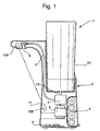
- Fig. 1 illustrates a cross-sectional view of a hands-free dispensing device, and a refill unit mounted therein wherein the refill unit includes a cap having a frangible device interface including a valve as will be described in more clearly with reference to the following figures.
- Figs. 2A , 2B and 2C illustrate a cross-sectional view of a frangible device interface including a valve, mounted on a bottle to form a refill unit, and a part of a dispensing device in (respectively) three relative positions, in Fig. 2A aligned but disengaged, in Fig. 2B aligned and partially engaged with the dispensing device, and in Fig. 2C aligned and fully engaged with the dispensing device.
- Fig. 3 illustrates in a perspective "exploded" view of the elements of the cap.
- Figs. 4 and 5 respectively illustrate a front perspective view and a side perspective view of a frangible device interface including a valve disengaged from and separated from a cap.
- the present invention provides a cap which includes a frangible device interface which comprises a valve part, which cap is specifically designed for a bottle (or other container) which provides a quantity of a liquid (e.g., soap, personal care composition, topical composition, shampoo, surface treatment composition and the like) which is then dispensed by an automatic dispenser.
- a liquid e.g., soap, personal care composition, topical composition, shampoo, surface treatment composition and the like
- valve part of the cap provides several benefits including: permitting for the total emptying of the bottle's contents; permitting for the entry of a stream or volume of water which may be used to flush out the interior of the bottle; as well as, physical separation of the valve part of the cap which may include a material which is difficult to recycle from the balance of the bottle and cap which, being preferably formed of recyclable thermoplastic polymers, may be more easily recycled.
- frangible device interface of the cap once the frangible device interface of the cap is removed from the cap, it cannot thereafter be reinserted to or mated to the cap in order to form a liquid or gas seal with the cap. Such is advantageous as if the user could remove the cap and refill the bottle, there is a danger that they would fill the bottle with a product which was incompatible with the dispensing device, which could would damage the dispensing device.
- the dispensing device may be one which is manually powered, e.g., a pump-type dispenser whereby a quantity of liquid is dispensed by manually operating the pump , viz., compressing it or squeezing it by hand.
- a pump-type dispenser whereby a quantity of liquid is dispensed by manually operating the pump , viz., compressing it or squeezing it by hand.
- the dispensing device may also be a device which includes a motor driven pump, such as disclosed in PCT/GB2009/002682 the contents of which are herein incorporated by reference thereto.
- Figure 1 illustrates a hands-free dispenser which is generally suitable for domestic use which includes the combination of a refill unit 1 with a base unit 2.
- the refill unit 1 provides a supply or a supply reservoir of a liquid or gel to be dispensed via the base unit 2.
- the refill unit 1 is removably insertable into the base unit 2 as described in more detail in the following figures.
- the base 2 has an interface 3 (not shown in Fig. 1 ) which is in fluid communication with a pump 4 driven by a motor 5, which pump is in turn in fluid communication with a dispensing nozzle 6 via an intermediate fluid tube 7.
- the pump 4 is selectively operable to pump a metered dose of the liquid or gel through fluid tube 7 and out the other end of the dispensing nozzle 6 in response to a suitable control or trigger signal.
- the base 2 further includes suitable controller logic circuitry 8 herein depicted as a printed circuit board having one or more solid-state components included thereon which operates as a controller means for the base 2, a power source, here depicted as an array of batteries 9, here four "AA" nominal 1.5 DC voltage batteries, and an infrared transmitter 10A which transmits an infrared beam (depicted) through a window 11 to an infrared receiver 10B noted to sense the presence of a user's hands in the vicinity of the base 2.
- the controller logic circuitry 8 is responsive to the signal from the infrared beam transmitter 10A and infrared receiver 10B to activate the pump.
- the illustrated infrared beam transmitter 10A and infrared receiver 10B are of the "break beam" type, however any known proximity sensor can be used.
- One such proximity sensor is a capacitance sensor, but others known to the art can be used in place of the beam transmitter 10A and infrared receiver 10B.
- a mechanical switch or other actuation means which requires physical contact with a user in order to activate the pump 4 in order to dispense a quantity of liquid or gel may be used in place of the proximity sensor wherein a hands-free mode of operation is unnecessary or not desired.
- the base 9 can be supplied by any suitable power source, including but not limited to direct connection to a power supply to wall mains power, or via an intermediate voltage step down transformer or other power supply intermediate the base 2 and the wall mains power.
- the base 2 may also be supplied with rechargeable batteries.
- the operation of rechargeable batteries may be supplemented by or the batteries may be charged by a photovoltaic panel responsive to light and which generates a current.
- a receptacle part 20 of the base unit 2 is shown, and which is configured to form a cup-shaped housing surrounding at least a part of the cap 40 of the refill unit 1.
- a spigot 14 rises upwardly from a base 15 and passes therethrough with the distal end 14A of the spigot 14 in fluid communication via a transfer tube 16 with the pump.
- the spigot 14 projects upwardly from the base 15, and at its proximal end 14B includes one or more castellations 14C which define one or more fluid passages 14D between adjacent castellations 14C.
- the exterior of the spigot 14 includes a surrounding O-ring 17 beneath the castellations 14C which forms a liquid tight seal when the spigot 14 is engaged with part of the cap 40.
- the cap 40 is mounted on the bottle 30 to form a refill unit 1.
- the bottle 30 has a neck 31 which fits over and seals to an annular sidewall 42 of the cap 40.
- the cap 40 has a cap face 41 extending between the annular sidewall 42, and an upwardly depending skirt 43 which defines the outer surface of the cap 40.
- the inner sidewall 43A of the skirt 43 includes retaining members 45 which cooperatively engage outwardly extending flanges 32 of the bottle 30 to provide further retention of the cap 40 on the bottle 30.
- the annular sidewall 42 extends inwardly into the interior of the cap 40 (and inwardly into the interior of the bottle 30) from the cap face 41 wherein it extends to a circular channel 46 which defines a frangible region of reduced thickness section of the material forming the cap the channel 46 being intermediate the annular sidewall 42 and the valve plate 47.
- a tethered pull-ring 70 which is configured to be retained within the interior cavity 48 defined by the annular sidewall 42, the valve plate 47 and the cap face 41.
- the valve plate 47 is recessed and spaced inwardly from the cap face 41.
- the tethered pull-ring 70 is recessed within the interior cavity 48, and is attached to the valve plate 47 at a point within the circular channel 45.
- the valve part of the cap 40 includes at least a liquid outlet leading from the interior of the bottle 30 and is formed as part of, or is mounted on the valve plate 47.
- the liquid outlet includes a valve plate 47, an annular wall 49 surrounding a central bore 50.
- a valve seat 51 At the top 54 of the annular wall 49 is a valve seat 51, here an inclined surface for an outlet valve element 52.
- the outlet valve element 52 is in the form of a U-shaped cup-like member but it may equally be any other shape, e.g., a solid member, a ball-shaped member, or a frustoconincal member or a cone.
- the outlet valve element 52 is biased into its closed position as depicted in Figs. 2A and 2B by a plurality of biasing elements 53. These are attached at their upper ends towards the top of the outlet valve element 52 and are attached at their lower ends at a location radially outward of the annular wall 49 and below the top 54 of the annular wall 49.
- the biasing elements 53 are resilient members and are formed as part of the outlet valve element. 52.
- the frangible device interface desirably further includes at least one pressure relief valve 60 which comprises at least an air inlet valve 61 in communication with the exterior of the cap 40 whereby air may be inlet into the interior of the bottle 30.
- the pressure relief valve 60 is optional it is desirably present and is separate from the liquid outlet.
- the pressure relief valve 60 includes an air inlet bore 62 offset from the central bore 50 but similarly extending through the valve plate 47.
- the air inlet bore 62 is in fluid communication with an annular barrier column 64 which extends axially to a level axially above the level of the top 54 of the annular wall 49.
- a suitable air valve 61 Intermediate the ends of the air inlet bore62 is a suitable air valve 61, here a conventional umbrella valve.
- the respective dimensions of the annular barrier column 64 and the central bore 50 are such that, when the pressure in the bottle 30 decreases when the liquid or gel is emptied from within the bottle, the pressure differential across the air valve 61 will become sufficient in order to allow air into the bottle 30. Any air entering via the air valve 61 also passes inwardly through the annular barrier column 64 which is above the level of the top of the annular wall 49, so that the air is not likely to become entrained in the outgoing liquid stream exiting the bottle via the cap 40.
- pressure relief valve 60 While a single pressure relief valve 60 is depicted, it is of course expected that a plurality of suitable pressure relief valves may be included in the cap 40, and preferably form part of the frangible device interface which is adapted to be removed from the cap 40 at an appropriate time. It is also expected that pressure relief valve(s) of a different configuration might also be used in conjunction with, or in place of the depicted pressure relief valve 60.
- the cap 40 may include one or more fixing posts 57 extending from the valve plate 47 in the direction of the central bore 50.
- the outlet valve element 52 may be connected to a valve base 58 having a plurality of valve base perforations 58A as depicted on Fig. 3 , via the intermediate connected biasing elements 53.
- the cap 40 may further include a fixing plate 59 which includes a plurality of fixing plate perforations 59A.
- the valve base perforations 58A and the fixing plate perforations 59A are suitable dimensioned to permit for the passage therethrough of the fixing posts 57, as can be more clearly understood from Fig. 3 . As is visible from Fig.
- the valve base 58 may be mounted on the valve plate 47 and thereafter the fixing plate 59 is mounted on the valve plate 47, with parts of the fixing posts 57 passing through both the valve base 58 and the fixing plate 59. While a friction fit of these elements is frequently suitable and sufficient, in some instances an intermediate adhesive may be used, or parts of the fixing posts may be suitably deformed such as by compression, via a snap-type fit, or via other physical deformation, or by thermally melting part of the fixing posts.
- the fixing posts 57 passing through both the valve base 58 and the fixing plate 59 also facilitate both the retention of and alignment of further parts of the cap 40, and in particular the valve part of the frangible device interface.
- FIG. 2A provided an illustration of the refill unit 1, including the bottle 30 and cap 40 aligned but disengaged, with part of the base unit 2.
- Fig. 2B there is now depicted the refill unit 1, including the bottle 30 and cap 40 aligned and partially engaged with the part of the base unit 2 wherein is illustrated the proximal end 14B of the spigot 14 engaged within the central bore 50 of the cap 40.
- the spigot 14 also extends through the tethered pull-ring 70.
- FIG. 2C there is depicted the refill unit 1 aligned and fully engaged (mounted upon, installed within) with the dispensing device.
- the bottle 30 and cap 40 are fully engaged with the part of the base unit 2.
- the proximal end 14B of the spigot 14 has caused the outlet valve element 52 to be displaced away from the valve seat 51 and causing it to rest upon the proximal end 14B of the spigot 14, which includes one or more castellations 14C which define one or more fluid passages 14D between adjacent castellations 14C.
- the liquid contained within the bottle 30 now passes via the fluid passages 14D inwardly into the interior of the spigot 14, wherein it passes to the transfer tube 16.
- the pressure relief valve 60 operates to admit air present within the interior cavity 48 into the interior of the refill unit 1, viz. the bottle 30.
- the spigot 14 is disengaged and the bias of the plurality of biasing elements 53 attached at their upper ends towards the top of the outlet valve element 52 operate to urge the outlet valve element 52 to be seated upon the valve seat 51, thereby denying further exit of the liquid contained within the bottle 30 through the open bore 50.
- the bottle 30 is a generally rigid plastic container containing liquid soap and the like.
- the bottle 1 is generally elliptical in cross-section. It may also be used to dispense other liquid or semi-liquid products (ideally with a viscosity greater than water), for use in personal care, e.g., topically applied compositions such as hand cream, body lotion, moisturizer, face cream, shampoo, shower gel, foaming hand wash, shaving cream, washing-up liquid, toothpaste, a sanitizing composition agent such as alcohol gel or other topically applied sanitizing composition.
- topically applied compositions such as hand cream, body lotion, moisturizer, face cream, shampoo, shower gel, foaming hand wash, shaving cream, washing-up liquid, toothpaste, a sanitizing composition agent such as alcohol gel or other topically applied sanitizing composition.
- the bottle may also be used to dispense other surface treatment compositions, (e.g., hard surface, soft surface) either directly to a locus to be treated, but preferentially onto a carrier material or substrate, such as a person's hand, a sponge, a brush, a wipe article, a disposable wipe article (napkin, tissue, paper towel, etc.) and the like.
- a carrier material or substrate such as a person's hand, a sponge, a brush, a wipe article, a disposable wipe article (napkin, tissue, paper towel, etc.) and the like.
- surface treatment compositions include those for the treatment of inanimate or nonporous hard surfaces, such as can be encountered in a kitchen or bath, dishware, tableware, pots, pans, textiles including garments, textiles, carpets, and the like.
- the bottle is specifically designed to be used in an inverted configuration on an automatic dispenser, as depicted in Fig. 1 , but such is to be understood as a non-limiting
- Figure 3 illustrates in a perspective "exploded" view the elements of the cap 40 of the invention which had been described in the prior figures.
- Figs. 4 and 5 respectively illustrate a front perspective view and a side perspective view of a frangible device interface including a valve disengaged from and a separated from a cap 40 of the invention.
- the frangible device interface 100 is separated from the remainder of the cap 40, and in this embodiment the frangible device interface 100 includes a valve part, here the outlet valve element 52 seated on the valve seat 51 of the annular wall 49, the valve plate within the confines of the circular channel 46 and the tethered pull-ring 70 attached to the valve plate 27.
- the frangible device interface 100 further includes the optional pressure relief valve 60, as is shown.
- the frangible device interface 100 is easily manually removed from the cap 40 by grasping or pulling on the pull-ring 70 which causes the reduced thickness section of the cap 40 in the region of the channel 46 to be breached, allowing for the separation of and withdrawal of the frangible device interface 100 from the cap 40.
- a user may flush out the interior of the bottle 30 such as with a quantity of water in order to clean any remaining liquid product from within the refill unit 1.
- the channel 46 is replaced by an O-ring sealing member, which permits for the reassembly of the frangible device interface 100 into the cap 40, which permits for the bottle 30 to be refilled with an appropriate liquid product, and be reused.
- the tethered pull ring may be substituted by an element having an geometry other than a ring shape.
Landscapes
- Engineering & Computer Science (AREA)
- Mechanical Engineering (AREA)
- Health & Medical Sciences (AREA)
- Public Health (AREA)
- Closures For Containers (AREA)
- Details Of Rigid Or Semi-Rigid Containers (AREA)
- Containers And Packaging Bodies Having A Special Means To Remove Contents (AREA)
Claims (5)
- Kappe (40) für eine Flasche (30), die eine zerbrechliche Vorrichtungsschnittstelle aufweist, umfassend einen Ventilteil, wobei die Flasche (30) ein Flüssig- oder Gelprodukt enthält und einen Hals (31) hat, auf dem die Kappe (40) montiert ist, wobei die Kappe eine Ventilplatte (47) und eine Kappenfläche (41) umfasst, wobei die Ventilplatte einen Flüssigkeitsauslass mit einer ringförmigen Wand, die eine mittlere Bohrung (50) umgibt, ein Auslassventilelement (52) und einen von der Ventilplatte herabhängenden angebundenen Zugring (70) aufweist, der im inneren Hohlraum (48) eingelassen ist, dadurch gekennzeichnet, dass die Kappe (40) einen durch eine ringförmige Seitenwand (42) definierten inneren Hohlraum (48) umfasst, wobei der Flüssigkeitsauslass aus dem Inneren der Flasche (30) in den inneren Hohlraum (48) führt, wobei die Kappe (40) ferner einen Kanal (46) zwischen der ringförmigen Seitenwand (42) und der Ventilplatte aufweist und der Kanal einen zerbrechlichen Bereich verringerter Dicke in dem die Kappe (40) bildenden Material definiert.
- Kappe für eine Flasche nach Anspruch 1, wobei die Ventilplatte ferner ein Druckentlastungsventil (60) aufweist.
- Kappe für eine Flasche nach einem der vorhergehenden Ansprüche, wobei das Auslassventilelement (52) durch ein oder mehrere Vorspannungselemente (53) gegen die ringförmige Wand (49) vorgespannt ist.
- Spender zum Spenden eines Flüssig- oder Gelprodukts, wobei der Spender eine Auffülleinheit (1), die eine Menge des zu spendenden Produkts enthält, und eine Basiseinheit (2) aufweist, durch die das Produkt gespendet wird, wobei die Basiseinheit (2) einen Behältnisteil (20) aufweist, der dazu konfiguriert ist, ein Gehäuse zur Aufnahme eines Teils einer Auffülleinheit (1) zu bilden, die eine Kappe (40) nach Anspruch 1 umfasst, die auf einer das Flüssigprodukt enthaltenden Flasche (30) montiert ist, wobei der Behältnisteil (20) eine Basis und einen nach oben vorragenden Hahn (14) aufweist, der an seinem proximalen Ende eine oder mehrere zinnenförmige Ausnehmungen (14C) und einen oder mehrere Durchgänge (14D) aufweist, wobei der Hahn (14) in der mittleren Bohrung (50) des Auslasses in Eingriff steht und das Auslassventilelement (52) vom Ventilsitz (51) weg verschiebt.
- Verfahren zur Verbesserung der Recyclefähigkeit einer Kappe (40) nach Anspruch 1 oder einer eine Kappe (40) nach Anspruch 1 umfassenden Auffülleinheit, wobei die Kappe (40) eine zerbrechliche Vorrichtungsschnittstelle einschließlich eines Ventils aufweist, wobei das Verfahren den Schritt des manuellen Entfernens der zerbrechlichen Vorrichtungsschnittstelle und des Ventils von der Kappe (40) oder ihrer anderweitigen Demontage, um sie von der Kappe (40) zu entfernen, und des Recycelns der Kappe (40) und/oder der die Kappe (40) umfassenden Auffülleinheit (1) separat von der zerbrechlichen Vorrichtungsschnittstelle aufweist.
Applications Claiming Priority (2)
| Application Number | Priority Date | Filing Date | Title |
|---|---|---|---|
| GB1018058.6A GB2484935A (en) | 2010-10-26 | 2010-10-26 | Container with frangible device interface |
| PCT/GB2011/052045 WO2012056219A1 (en) | 2010-10-26 | 2011-10-21 | Container with frangible device interface |
Publications (2)
| Publication Number | Publication Date |
|---|---|
| EP2632817A1 EP2632817A1 (de) | 2013-09-04 |
| EP2632817B1 true EP2632817B1 (de) | 2014-12-03 |
Family
ID=43365526
Family Applications (1)
| Application Number | Title | Priority Date | Filing Date |
|---|---|---|---|
| EP11776499.3A Not-in-force EP2632817B1 (de) | 2010-10-26 | 2011-10-21 | Behälter mit zerbrechlicher geräteschnittstelle |
Country Status (5)
| Country | Link |
|---|---|
| US (1) | US9033193B2 (de) |
| EP (1) | EP2632817B1 (de) |
| JP (1) | JP5749345B2 (de) |
| GB (1) | GB2484935A (de) |
| WO (1) | WO2012056219A1 (de) |
Cited By (1)
| Publication number | Priority date | Publication date | Assignee | Title |
|---|---|---|---|---|
| AT522213A2 (de) * | 2019-03-13 | 2020-09-15 | Georg Hagleitner Hans | Behälter und Set aus Spender und Behälter |
Families Citing this family (8)
| Publication number | Priority date | Publication date | Assignee | Title |
|---|---|---|---|---|
| CA2940525C (en) | 2014-02-24 | 2023-01-31 | Gojo Industries, Inc. | Vented non-collapsing containers, refillable refill containers, dispensers and refill units |
| JP6250485B2 (ja) * | 2014-06-25 | 2017-12-20 | 株式会社コーセー | リフィル容器用注出構造と該構造を備えたリフィル容器、および該リフィル容器に液状化粧料を充填した化粧料製品 |
| US9884336B2 (en) * | 2014-10-10 | 2018-02-06 | The Procter & Gamble Company | Multifunctional dispensing device for dispensing fluid compositions |
| US9949599B2 (en) * | 2015-06-17 | 2018-04-24 | Gojo Industries, Inc. | Vent valves and refill units with vent valves for use with inverted non-collapsing containers |
| US10022024B2 (en) * | 2015-10-23 | 2018-07-17 | Gojo Industries, Inc. | Rotary peristaltic dome pump |
| US11891236B2 (en) | 2020-02-25 | 2024-02-06 | Pvpallet, Inc. | Transport container |
| US11857505B2 (en) | 2020-10-05 | 2024-01-02 | Express Scripts Strategic Development, Inc. | Smart pill dispenser |
| US11800957B2 (en) | 2021-03-12 | 2023-10-31 | Salto, Llc | Amenity fluid dispensing system |
Family Cites Families (9)
| Publication number | Priority date | Publication date | Assignee | Title |
|---|---|---|---|---|
| US3227317A (en) * | 1963-06-06 | 1966-01-04 | Shell Oil Co | Closure assembly for containers |
| US4895282A (en) * | 1988-08-01 | 1990-01-23 | Owens-Illinois Closure Inc. | Dispensing closure with pull tab for enlarging orifice |
| DE10125842B4 (de) * | 2001-05-25 | 2005-06-09 | Höhensteiger, Alois | Spender für flüssige Medien wie Flüssigseife, Desinfektionsmittel etc. |
| US6568563B2 (en) * | 2001-08-14 | 2003-05-27 | Portola Packaging, Inc. | Closure having well with removable membrane |
| GB2429452A (en) * | 2005-08-27 | 2007-02-28 | Ebac Ltd | Bottle cap and valve assembly for a bottled water station |
| FR2900909B1 (fr) * | 2006-05-12 | 2008-06-13 | Bericap Sarl | Bouchon de versement de liquides a debit reglable |
| GB0820984D0 (en) * | 2008-11-17 | 2008-12-24 | Reckitt & Colman Overseas | A bottle with a tamper-proof cap |
| GB0820978D0 (en) | 2008-11-17 | 2008-12-24 | Reckitt & Colman Overseas | A relief valve |
| GB0820981D0 (en) * | 2008-11-17 | 2008-12-24 | Reckitt & Colman Overseas | Dispenser and refill unit |
-
2010
- 2010-10-26 GB GB1018058.6A patent/GB2484935A/en not_active Withdrawn
-
2011
- 2011-10-21 EP EP11776499.3A patent/EP2632817B1/de not_active Not-in-force
- 2011-10-21 WO PCT/GB2011/052045 patent/WO2012056219A1/en not_active Ceased
- 2011-10-21 US US13/880,658 patent/US9033193B2/en not_active Expired - Fee Related
- 2011-10-21 JP JP2013535506A patent/JP5749345B2/ja not_active Expired - Fee Related
Cited By (3)
| Publication number | Priority date | Publication date | Assignee | Title |
|---|---|---|---|---|
| AT522213A2 (de) * | 2019-03-13 | 2020-09-15 | Georg Hagleitner Hans | Behälter und Set aus Spender und Behälter |
| AT522213A3 (de) * | 2019-03-13 | 2020-10-15 | Georg Hagleitner Hans | Behälter und Set aus Spender und Behälter |
| AT522213B1 (de) * | 2019-03-13 | 2021-04-15 | Georg Hagleitner Hans | Behälter und Set aus Spender und Behälter |
Also Published As
| Publication number | Publication date |
|---|---|
| JP2014500199A (ja) | 2014-01-09 |
| GB2484935A (en) | 2012-05-02 |
| JP5749345B2 (ja) | 2015-07-15 |
| GB201018058D0 (en) | 2010-12-08 |
| US9033193B2 (en) | 2015-05-19 |
| WO2012056219A1 (en) | 2012-05-03 |
| US20130200073A1 (en) | 2013-08-08 |
| EP2632817A1 (de) | 2013-09-04 |
Similar Documents
| Publication | Publication Date | Title |
|---|---|---|
| EP2632817B1 (de) | Behälter mit zerbrechlicher geräteschnittstelle | |
| EP2648585B1 (de) | Schaumflüssigkeitsabgabevorrichtung mit schaumrückgewinnung | |
| EP2365933B1 (de) | Abgabevorrichtung mit nachfülleinheit | |
| EP2814367B1 (de) | Spender mit einem neigungssensor | |
| JP3200206U (ja) | 発泡性液体ディスペンサ | |
| US20110036867A1 (en) | Secure dispensing system for multiple consumables | |
| AU2009315390B2 (en) | A bottle with a tamper-proof cap | |
| EP3367861B1 (de) | Spender | |
| JP2001082342A (ja) | コンパクトな流体ポンプ | |
| US20130134183A1 (en) | Liquid delivery system | |
| EP2618797A1 (de) | Vorrichtung | |
| WO2011135336A1 (en) | A liquid delivery system | |
| US20130192718A1 (en) | Kit comprising a liquid container and a refill device | |
| GB2468728A (en) | Dispensing Apparatus and Method |
Legal Events
| Date | Code | Title | Description |
|---|---|---|---|
| PUAI | Public reference made under article 153(3) epc to a published international application that has entered the european phase |
Free format text: ORIGINAL CODE: 0009012 |
|
| 17P | Request for examination filed |
Effective date: 20130415 |
|
| AK | Designated contracting states |
Kind code of ref document: A1 Designated state(s): AL AT BE BG CH CY CZ DE DK EE ES FI FR GB GR HR HU IE IS IT LI LT LU LV MC MK MT NL NO PL PT RO RS SE SI SK SM TR |
|
| DAX | Request for extension of the european patent (deleted) | ||
| GRAP | Despatch of communication of intention to grant a patent |
Free format text: ORIGINAL CODE: EPIDOSNIGR1 |
|
| INTG | Intention to grant announced |
Effective date: 20140926 |
|
| GRAS | Grant fee paid |
Free format text: ORIGINAL CODE: EPIDOSNIGR3 |
|
| GRAA | (expected) grant |
Free format text: ORIGINAL CODE: 0009210 |
|
| AK | Designated contracting states |
Kind code of ref document: B1 Designated state(s): AL AT BE BG CH CY CZ DE DK EE ES FI FR GB GR HR HU IE IS IT LI LT LU LV MC MK MT NL NO PL PT RO RS SE SI SK SM TR |
|
| REG | Reference to a national code |
Ref country code: GB Ref legal event code: FG4D |
|
| REG | Reference to a national code |
Ref country code: AT Ref legal event code: REF Ref document number: 699215 Country of ref document: AT Kind code of ref document: T Effective date: 20141215 Ref country code: CH Ref legal event code: EP |
|
| REG | Reference to a national code |
Ref country code: IE Ref legal event code: FG4D |
|
| REG | Reference to a national code |
Ref country code: DE Ref legal event code: R096 Ref document number: 602011011997 Country of ref document: DE Effective date: 20150115 |
|
| REG | Reference to a national code |
Ref country code: NL Ref legal event code: VDEP Effective date: 20141203 |
|
| REG | Reference to a national code |
Ref country code: AT Ref legal event code: MK05 Ref document number: 699215 Country of ref document: AT Kind code of ref document: T Effective date: 20141203 |
|
| PG25 | Lapsed in a contracting state [announced via postgrant information from national office to epo] |
Ref country code: ES Free format text: LAPSE BECAUSE OF FAILURE TO SUBMIT A TRANSLATION OF THE DESCRIPTION OR TO PAY THE FEE WITHIN THE PRESCRIBED TIME-LIMIT Effective date: 20141203 Ref country code: NL Free format text: LAPSE BECAUSE OF FAILURE TO SUBMIT A TRANSLATION OF THE DESCRIPTION OR TO PAY THE FEE WITHIN THE PRESCRIBED TIME-LIMIT Effective date: 20141203 Ref country code: NO Free format text: LAPSE BECAUSE OF FAILURE TO SUBMIT A TRANSLATION OF THE DESCRIPTION OR TO PAY THE FEE WITHIN THE PRESCRIBED TIME-LIMIT Effective date: 20150303 Ref country code: LT Free format text: LAPSE BECAUSE OF FAILURE TO SUBMIT A TRANSLATION OF THE DESCRIPTION OR TO PAY THE FEE WITHIN THE PRESCRIBED TIME-LIMIT Effective date: 20141203 Ref country code: FI Free format text: LAPSE BECAUSE OF FAILURE TO SUBMIT A TRANSLATION OF THE DESCRIPTION OR TO PAY THE FEE WITHIN THE PRESCRIBED TIME-LIMIT Effective date: 20141203 |
|
| REG | Reference to a national code |
Ref country code: LT Ref legal event code: MG4D |
|
| PG25 | Lapsed in a contracting state [announced via postgrant information from national office to epo] |
Ref country code: GR Free format text: LAPSE BECAUSE OF FAILURE TO SUBMIT A TRANSLATION OF THE DESCRIPTION OR TO PAY THE FEE WITHIN THE PRESCRIBED TIME-LIMIT Effective date: 20150304 Ref country code: HR Free format text: LAPSE BECAUSE OF FAILURE TO SUBMIT A TRANSLATION OF THE DESCRIPTION OR TO PAY THE FEE WITHIN THE PRESCRIBED TIME-LIMIT Effective date: 20141203 Ref country code: AT Free format text: LAPSE BECAUSE OF FAILURE TO SUBMIT A TRANSLATION OF THE DESCRIPTION OR TO PAY THE FEE WITHIN THE PRESCRIBED TIME-LIMIT Effective date: 20141203 Ref country code: RS Free format text: LAPSE BECAUSE OF FAILURE TO SUBMIT A TRANSLATION OF THE DESCRIPTION OR TO PAY THE FEE WITHIN THE PRESCRIBED TIME-LIMIT Effective date: 20141203 Ref country code: SE Free format text: LAPSE BECAUSE OF FAILURE TO SUBMIT A TRANSLATION OF THE DESCRIPTION OR TO PAY THE FEE WITHIN THE PRESCRIBED TIME-LIMIT Effective date: 20141203 Ref country code: LV Free format text: LAPSE BECAUSE OF FAILURE TO SUBMIT A TRANSLATION OF THE DESCRIPTION OR TO PAY THE FEE WITHIN THE PRESCRIBED TIME-LIMIT Effective date: 20141203 Ref country code: CY Free format text: LAPSE BECAUSE OF FAILURE TO SUBMIT A TRANSLATION OF THE DESCRIPTION OR TO PAY THE FEE WITHIN THE PRESCRIBED TIME-LIMIT Effective date: 20141203 |
|
| PG25 | Lapsed in a contracting state [announced via postgrant information from national office to epo] |
Ref country code: PT Free format text: LAPSE BECAUSE OF FAILURE TO SUBMIT A TRANSLATION OF THE DESCRIPTION OR TO PAY THE FEE WITHIN THE PRESCRIBED TIME-LIMIT Effective date: 20150403 Ref country code: EE Free format text: LAPSE BECAUSE OF FAILURE TO SUBMIT A TRANSLATION OF THE DESCRIPTION OR TO PAY THE FEE WITHIN THE PRESCRIBED TIME-LIMIT Effective date: 20141203 Ref country code: SK Free format text: LAPSE BECAUSE OF FAILURE TO SUBMIT A TRANSLATION OF THE DESCRIPTION OR TO PAY THE FEE WITHIN THE PRESCRIBED TIME-LIMIT Effective date: 20141203 Ref country code: CZ Free format text: LAPSE BECAUSE OF FAILURE TO SUBMIT A TRANSLATION OF THE DESCRIPTION OR TO PAY THE FEE WITHIN THE PRESCRIBED TIME-LIMIT Effective date: 20141203 Ref country code: RO Free format text: LAPSE BECAUSE OF FAILURE TO SUBMIT A TRANSLATION OF THE DESCRIPTION OR TO PAY THE FEE WITHIN THE PRESCRIBED TIME-LIMIT Effective date: 20141203 |
|
| PG25 | Lapsed in a contracting state [announced via postgrant information from national office to epo] |
Ref country code: IS Free format text: LAPSE BECAUSE OF FAILURE TO SUBMIT A TRANSLATION OF THE DESCRIPTION OR TO PAY THE FEE WITHIN THE PRESCRIBED TIME-LIMIT Effective date: 20150403 Ref country code: PL Free format text: LAPSE BECAUSE OF FAILURE TO SUBMIT A TRANSLATION OF THE DESCRIPTION OR TO PAY THE FEE WITHIN THE PRESCRIBED TIME-LIMIT Effective date: 20141203 |
|
| REG | Reference to a national code |
Ref country code: DE Ref legal event code: R097 Ref document number: 602011011997 Country of ref document: DE |
|
| PLBE | No opposition filed within time limit |
Free format text: ORIGINAL CODE: 0009261 |
|
| STAA | Information on the status of an ep patent application or granted ep patent |
Free format text: STATUS: NO OPPOSITION FILED WITHIN TIME LIMIT |
|
| REG | Reference to a national code |
Ref country code: FR Ref legal event code: PLFP Year of fee payment: 5 |
|
| PG25 | Lapsed in a contracting state [announced via postgrant information from national office to epo] |
Ref country code: DK Free format text: LAPSE BECAUSE OF FAILURE TO SUBMIT A TRANSLATION OF THE DESCRIPTION OR TO PAY THE FEE WITHIN THE PRESCRIBED TIME-LIMIT Effective date: 20141203 |
|
| 26N | No opposition filed |
Effective date: 20150904 |
|
| PG25 | Lapsed in a contracting state [announced via postgrant information from national office to epo] |
Ref country code: IT Free format text: LAPSE BECAUSE OF FAILURE TO SUBMIT A TRANSLATION OF THE DESCRIPTION OR TO PAY THE FEE WITHIN THE PRESCRIBED TIME-LIMIT Effective date: 20141203 |
|
| PG25 | Lapsed in a contracting state [announced via postgrant information from national office to epo] |
Ref country code: SI Free format text: LAPSE BECAUSE OF FAILURE TO SUBMIT A TRANSLATION OF THE DESCRIPTION OR TO PAY THE FEE WITHIN THE PRESCRIBED TIME-LIMIT Effective date: 20141203 |
|
| PG25 | Lapsed in a contracting state [announced via postgrant information from national office to epo] |
Ref country code: LU Free format text: LAPSE BECAUSE OF FAILURE TO SUBMIT A TRANSLATION OF THE DESCRIPTION OR TO PAY THE FEE WITHIN THE PRESCRIBED TIME-LIMIT Effective date: 20151021 Ref country code: BE Free format text: LAPSE BECAUSE OF FAILURE TO SUBMIT A TRANSLATION OF THE DESCRIPTION OR TO PAY THE FEE WITHIN THE PRESCRIBED TIME-LIMIT Effective date: 20141203 |
|
| REG | Reference to a national code |
Ref country code: CH Ref legal event code: PL |
|
| PG25 | Lapsed in a contracting state [announced via postgrant information from national office to epo] |
Ref country code: MC Free format text: LAPSE BECAUSE OF FAILURE TO SUBMIT A TRANSLATION OF THE DESCRIPTION OR TO PAY THE FEE WITHIN THE PRESCRIBED TIME-LIMIT Effective date: 20141203 |
|
| REG | Reference to a national code |
Ref country code: IE Ref legal event code: MM4A |
|
| PG25 | Lapsed in a contracting state [announced via postgrant information from national office to epo] |
Ref country code: CH Free format text: LAPSE BECAUSE OF NON-PAYMENT OF DUE FEES Effective date: 20151031 Ref country code: LI Free format text: LAPSE BECAUSE OF NON-PAYMENT OF DUE FEES Effective date: 20151031 |
|
| REG | Reference to a national code |
Ref country code: FR Ref legal event code: PLFP Year of fee payment: 6 |
|
| PG25 | Lapsed in a contracting state [announced via postgrant information from national office to epo] |
Ref country code: IE Free format text: LAPSE BECAUSE OF NON-PAYMENT OF DUE FEES Effective date: 20151021 |
|
| PG25 | Lapsed in a contracting state [announced via postgrant information from national office to epo] |
Ref country code: HU Free format text: LAPSE BECAUSE OF FAILURE TO SUBMIT A TRANSLATION OF THE DESCRIPTION OR TO PAY THE FEE WITHIN THE PRESCRIBED TIME-LIMIT; INVALID AB INITIO Effective date: 20111021 Ref country code: BG Free format text: LAPSE BECAUSE OF FAILURE TO SUBMIT A TRANSLATION OF THE DESCRIPTION OR TO PAY THE FEE WITHIN THE PRESCRIBED TIME-LIMIT Effective date: 20141203 Ref country code: SM Free format text: LAPSE BECAUSE OF FAILURE TO SUBMIT A TRANSLATION OF THE DESCRIPTION OR TO PAY THE FEE WITHIN THE PRESCRIBED TIME-LIMIT Effective date: 20141203 |
|
| PG25 | Lapsed in a contracting state [announced via postgrant information from national office to epo] |
Ref country code: MT Free format text: LAPSE BECAUSE OF FAILURE TO SUBMIT A TRANSLATION OF THE DESCRIPTION OR TO PAY THE FEE WITHIN THE PRESCRIBED TIME-LIMIT Effective date: 20141203 |
|
| REG | Reference to a national code |
Ref country code: FR Ref legal event code: PLFP Year of fee payment: 7 |
|
| PG25 | Lapsed in a contracting state [announced via postgrant information from national office to epo] |
Ref country code: TR Free format text: LAPSE BECAUSE OF FAILURE TO SUBMIT A TRANSLATION OF THE DESCRIPTION OR TO PAY THE FEE WITHIN THE PRESCRIBED TIME-LIMIT Effective date: 20141203 Ref country code: MK Free format text: LAPSE BECAUSE OF FAILURE TO SUBMIT A TRANSLATION OF THE DESCRIPTION OR TO PAY THE FEE WITHIN THE PRESCRIBED TIME-LIMIT Effective date: 20141203 |
|
| REG | Reference to a national code |
Ref country code: FR Ref legal event code: PLFP Year of fee payment: 8 |
|
| PG25 | Lapsed in a contracting state [announced via postgrant information from national office to epo] |
Ref country code: AL Free format text: LAPSE BECAUSE OF FAILURE TO SUBMIT A TRANSLATION OF THE DESCRIPTION OR TO PAY THE FEE WITHIN THE PRESCRIBED TIME-LIMIT Effective date: 20141203 |
|
| REG | Reference to a national code |
Ref country code: DE Ref legal event code: R081 Ref document number: 602011011997 Country of ref document: DE Owner name: RB HEALTH (US) LLC, PARSIPPANY, US Free format text: FORMER OWNER: RECKITT BENCKISER LLC, PARSIPPANY, N.J., US |
|
| REG | Reference to a national code |
Ref country code: GB Ref legal event code: 732E Free format text: REGISTERED BETWEEN 20200917 AND 20200923 |
|
| PGFP | Annual fee paid to national office [announced via postgrant information from national office to epo] |
Ref country code: FR Payment date: 20210913 Year of fee payment: 11 |
|
| PGFP | Annual fee paid to national office [announced via postgrant information from national office to epo] |
Ref country code: GB Payment date: 20210915 Year of fee payment: 11 |
|
| PGFP | Annual fee paid to national office [announced via postgrant information from national office to epo] |
Ref country code: DE Payment date: 20210908 Year of fee payment: 11 |
|
| REG | Reference to a national code |
Ref country code: DE Ref legal event code: R119 Ref document number: 602011011997 Country of ref document: DE |
|
| GBPC | Gb: european patent ceased through non-payment of renewal fee |
Effective date: 20221021 |
|
| PG25 | Lapsed in a contracting state [announced via postgrant information from national office to epo] |
Ref country code: FR Free format text: LAPSE BECAUSE OF NON-PAYMENT OF DUE FEES Effective date: 20221031 Ref country code: DE Free format text: LAPSE BECAUSE OF NON-PAYMENT OF DUE FEES Effective date: 20230503 |
|
| PG25 | Lapsed in a contracting state [announced via postgrant information from national office to epo] |
Ref country code: GB Free format text: LAPSE BECAUSE OF NON-PAYMENT OF DUE FEES Effective date: 20221021 |