EP2814367B1 - Spender mit einem neigungssensor - Google Patents
Spender mit einem neigungssensor Download PDFInfo
- Publication number
- EP2814367B1 EP2814367B1 EP13705001.9A EP13705001A EP2814367B1 EP 2814367 B1 EP2814367 B1 EP 2814367B1 EP 13705001 A EP13705001 A EP 13705001A EP 2814367 B1 EP2814367 B1 EP 2814367B1
- Authority
- EP
- European Patent Office
- Prior art keywords
- dispenser
- annular wall
- valve element
- base unit
- liquid
- Prior art date
- Legal status (The legal status is an assumption and is not a legal conclusion. Google has not performed a legal analysis and makes no representation as to the accuracy of the status listed.)
- Not-in-force
Links
Images


Classifications
-
- A—HUMAN NECESSITIES
- A47—FURNITURE; DOMESTIC ARTICLES OR APPLIANCES; COFFEE MILLS; SPICE MILLS; SUCTION CLEANERS IN GENERAL
- A47K—SANITARY EQUIPMENT; ACCESSORIES THEREFOR, e.g. TOILET ACCESSORIES
- A47K5/00—Holders or dispensers for soap, toothpaste or the like
- A47K5/06—Dispensers for soap
- A47K5/12—Dispensers for soap for liquid or pasty soap
- A47K5/1217—Electrical control means for the dispensing mechanism
-
- A—HUMAN NECESSITIES
- A47—FURNITURE; DOMESTIC ARTICLES OR APPLIANCES; COFFEE MILLS; SPICE MILLS; SUCTION CLEANERS IN GENERAL
- A47K—SANITARY EQUIPMENT; ACCESSORIES THEREFOR, e.g. TOILET ACCESSORIES
- A47K5/00—Holders or dispensers for soap, toothpaste or the like
- A47K5/06—Dispensers for soap
- A47K5/12—Dispensers for soap for liquid or pasty soap
- A47K5/1201—Dispensers for soap for liquid or pasty soap hand-carried
-
- B—PERFORMING OPERATIONS; TRANSPORTING
- B65—CONVEYING; PACKING; STORING; HANDLING THIN OR FILAMENTARY MATERIAL
- B65D—CONTAINERS FOR STORAGE OR TRANSPORT OF ARTICLES OR MATERIALS, e.g. BAGS, BARRELS, BOTTLES, BOXES, CANS, CARTONS, CRATES, DRUMS, JARS, TANKS, HOPPERS, FORWARDING CONTAINERS; ACCESSORIES, CLOSURES, OR FITTINGS THEREFOR; PACKAGING ELEMENTS; PACKAGES
- B65D47/00—Closures with filling and discharging, or with discharging, devices
- B65D47/04—Closures with discharging devices other than pumps
- B65D47/20—Closures with discharging devices other than pumps comprising hand-operated members for controlling discharge
- B65D47/2018—Closures with discharging devices other than pumps comprising hand-operated members for controlling discharge comprising a valve or like element which is opened or closed by deformation of the container or closure
- B65D47/2031—Closures with discharging devices other than pumps comprising hand-operated members for controlling discharge comprising a valve or like element which is opened or closed by deformation of the container or closure the element being formed by a slit, narrow opening or constrictable spout, the size of the outlet passage being able to be varied by increasing or decreasing the pressure
-
- B—PERFORMING OPERATIONS; TRANSPORTING
- B65—CONVEYING; PACKING; STORING; HANDLING THIN OR FILAMENTARY MATERIAL
- B65D—CONTAINERS FOR STORAGE OR TRANSPORT OF ARTICLES OR MATERIALS, e.g. BAGS, BARRELS, BOTTLES, BOXES, CANS, CARTONS, CRATES, DRUMS, JARS, TANKS, HOPPERS, FORWARDING CONTAINERS; ACCESSORIES, CLOSURES, OR FITTINGS THEREFOR; PACKAGING ELEMENTS; PACKAGES
- B65D83/00—Containers or packages with special means for dispensing contents
- B65D83/14—Containers for dispensing liquid or semi-liquid contents by internal gaseous pressure, i.e. aerosol containers comprising propellant
- B65D83/16—Actuating means
- B65D83/26—Actuating means operating automatically, e.g. periodically
- B65D83/262—Actuating means operating automatically, e.g. periodically by clockwork, motor, electric or magnetic means operating without repeated human input
-
- B—PERFORMING OPERATIONS; TRANSPORTING
- B67—OPENING, CLOSING OR CLEANING BOTTLES, JARS OR SIMILAR CONTAINERS; LIQUID HANDLING
- B67D—DISPENSING, DELIVERING OR TRANSFERRING LIQUIDS, NOT OTHERWISE PROVIDED FOR
- B67D3/00—Apparatus or devices for controlling flow of liquids under gravity from storage containers for dispensing purposes
- B67D3/0003—Apparatus or devices for controlling flow of liquids under gravity from storage containers for dispensing purposes provided with automatic fluid control means
-
- F—MECHANICAL ENGINEERING; LIGHTING; HEATING; WEAPONS; BLASTING
- F16—ENGINEERING ELEMENTS AND UNITS; GENERAL MEASURES FOR PRODUCING AND MAINTAINING EFFECTIVE FUNCTIONING OF MACHINES OR INSTALLATIONS; THERMAL INSULATION IN GENERAL
- F16K—VALVES; TAPS; COCKS; ACTUATING-FLOATS; DEVICES FOR VENTING OR AERATING
- F16K15/00—Check valves
- F16K15/14—Check valves with flexible valve members
- F16K15/144—Check valves with flexible valve members the closure elements being fixed along all or a part of their periphery
- F16K15/145—Check valves with flexible valve members the closure elements being fixed along all or a part of their periphery the closure elements being shaped as a solids of revolution, e.g. cylindrical or conical
-
- F—MECHANICAL ENGINEERING; LIGHTING; HEATING; WEAPONS; BLASTING
- F16—ENGINEERING ELEMENTS AND UNITS; GENERAL MEASURES FOR PRODUCING AND MAINTAINING EFFECTIVE FUNCTIONING OF MACHINES OR INSTALLATIONS; THERMAL INSULATION IN GENERAL
- F16K—VALVES; TAPS; COCKS; ACTUATING-FLOATS; DEVICES FOR VENTING OR AERATING
- F16K17/00—Safety valves; Equalising valves, e.g. pressure relief valves
- F16K17/02—Safety valves; Equalising valves, e.g. pressure relief valves opening on surplus pressure on one side; closing on insufficient pressure on one side
- F16K17/04—Safety valves; Equalising valves, e.g. pressure relief valves opening on surplus pressure on one side; closing on insufficient pressure on one side spring-loaded
- F16K17/08—Safety valves; Equalising valves, e.g. pressure relief valves opening on surplus pressure on one side; closing on insufficient pressure on one side spring-loaded with special arrangements for providing a large discharge passage
- F16K17/085—Safety valves; Equalising valves, e.g. pressure relief valves opening on surplus pressure on one side; closing on insufficient pressure on one side spring-loaded with special arrangements for providing a large discharge passage with diaphragm
-
- F—MECHANICAL ENGINEERING; LIGHTING; HEATING; WEAPONS; BLASTING
- F16—ENGINEERING ELEMENTS AND UNITS; GENERAL MEASURES FOR PRODUCING AND MAINTAINING EFFECTIVE FUNCTIONING OF MACHINES OR INSTALLATIONS; THERMAL INSULATION IN GENERAL
- F16K—VALVES; TAPS; COCKS; ACTUATING-FLOATS; DEVICES FOR VENTING OR AERATING
- F16K17/00—Safety valves; Equalising valves, e.g. pressure relief valves
- F16K17/02—Safety valves; Equalising valves, e.g. pressure relief valves opening on surplus pressure on one side; closing on insufficient pressure on one side
- F16K17/04—Safety valves; Equalising valves, e.g. pressure relief valves opening on surplus pressure on one side; closing on insufficient pressure on one side spring-loaded
- F16K17/08—Safety valves; Equalising valves, e.g. pressure relief valves opening on surplus pressure on one side; closing on insufficient pressure on one side spring-loaded with special arrangements for providing a large discharge passage
- F16K17/087—Safety valves; Equalising valves, e.g. pressure relief valves opening on surplus pressure on one side; closing on insufficient pressure on one side spring-loaded with special arrangements for providing a large discharge passage with bellows
-
- H—ELECTRICITY
- H03—ELECTRONIC CIRCUITRY
- H03K—PULSE TECHNIQUE
- H03K17/00—Electronic switching or gating, i.e. not by contact-making and –breaking
- H03K17/94—Electronic switching or gating, i.e. not by contact-making and –breaking characterised by the way in which the control signals are generated
- H03K17/945—Proximity switches
-
- Y—GENERAL TAGGING OF NEW TECHNOLOGICAL DEVELOPMENTS; GENERAL TAGGING OF CROSS-SECTIONAL TECHNOLOGIES SPANNING OVER SEVERAL SECTIONS OF THE IPC; TECHNICAL SUBJECTS COVERED BY FORMER USPC CROSS-REFERENCE ART COLLECTIONS [XRACs] AND DIGESTS
- Y10—TECHNICAL SUBJECTS COVERED BY FORMER USPC
- Y10T—TECHNICAL SUBJECTS COVERED BY FORMER US CLASSIFICATION
- Y10T137/00—Fluid handling
- Y10T137/9029—With coupling
Definitions
- the present invention relates to a dispenser for dispensing a liquid, such as liquid soaps useful in hand washing as well as light duty dishwashing detergent soaps useful for the manual cleaning of dishware.
- the dispenser may also be used to dispense liquids which are useful in the cleaning of surfaces such as hard surfaces, and soft surfaces.
- One advantageous device is a dispenser and refill unit disclosed in WO 2010/055314 A1 according to the preamble of claim 1.
- the device has a base unit into which a refill unit containing the material to be dispensed is fitted in an inverted configuration, namely with its outlet at the lowermost end.
- the device is a so-called hands-free dispenser which is generally suitable for domestic use.
- the device is intended to be placed upon a flat, generally horizontal surface and responsive to the "breaking" of (interrupting) an infrared beam originating between an infrared transmitter proximate to the dispensing nozzle and a receiver positioned within the base of the device, which is the sole manner in which the delivered dose of the soap can be caused to occur.
- the device is well suited for the metered delivery of a dose of the soap to the hands of a user of the device which occurs when the hands (or article) are held in near proximity to the nozzle, thereby breaking the infrared beam, the device is not suited to deliver such a metered dose of the soap in any other manner.
- a dispenser comprising a base unit with an actuation mechanism for dispensing liquid and a refill unit insertible into the base unit in an inverted configuration with its outlet lowermost for the supply of liquid to the base unit, the refill unit comprising an annular wall projecting into the refill unit and defining an outlet from the refill unit, the annular wall being closable at its innermost end by a valve element biased onto the annular wall, the base unit comprising a hollow spigot and an annular seal surrounding and spaced from the top of the spigot whereby insertion of the refill unit into the base unit causes the spigot to enter the annular wall and to lift the valve element from the annular wall to define a flow path from the refill unit, through at least one cut-out portion formed in the top of the spigot and/or the bottom of the valve element and down the hollow spigot, and the annular seal to seal between the spigot and the annular wall, wherein the base unit also comprises a proximity sensor means, and an inclination sensor means
- a inclination sensor means which is responsive to the change in the position of the device and an angular displacement with respect to the normal vertical positioning of the body of the device when it is placed upon a generally horizontal surface, which inclination sensor means functions to trigger the device and thus thereby deliver a dose of the liquid to be dispensed.
- Such an inclination sensor means is distinguished from a proximity sensor means, as it is responsive to the angular displacement of the device, irregardless of the placement of hands or any other article proximate to the device, e.g., within the infrared beam.
- inclination sensor means allows for one or more metered doses of the soap to be dispensed from the device, by merely “tilting” and inclining the base of the device to a position other than the normally vertical position of the device.
- the inclination sensor means is responsive when the device is tilted and angularly displaced forwardly, that is to say in the direction of the dispensing nozzle part of the device, whereby the base of the device is tilted by a minimum angle "A”, also referred to as a "tilt angle".
- the present invention has been specifically designed for a free-standing liquid dispenser suitable for use in a domestic environment.
- a demountable or hingedly affixed wall-mounted unit which can be suitable inclined and could be useful in larger scale devices, e.g., such as devices for use in public lavatories.
- Such an arrangement of a base unit and insertable refill unit provides a mechanism by which the refill unit can simply be lowered onto the spigot. This causes the flow path to be opened up.
- the annular seal forms a seal with the annular wall thereby preventing leakage even during the opening process.
- doses of the liquid e.g., liquid soap, may be delivered.
- the present disclosure further provides a method of dispensing a liquid from the dispenser, being based upon the relative inclination of the base unit of the dispenser to the horizontal.
- the invention is disclosed hereinafter.
- the dispenser is a hands-free dispenser which is generally suitable for domestic use.
- the dispenser is primarily intended to dispense liquid soap, but may also be used to dispense other liquid or semi-liquid products (ideally with a viscosity greater than water), such as hand cream, body lotion, moisturiser, face cream, shampoo, shower gel, foaming hand wash, shaving cream, washing up liquid, toothpaste, acne treatment cream, a surface cleaner or a sanitising agent such as alcohol gel.
- the dispenser comprises an inclination sensor means, which triggers the actuation means causing the device to operate to deliver one or more doses of soap from the dispenser, the dispenser may be used to dispense a quantity of liquid soap, preferably one or more metered doses of liquid soap, responsive to this aforesaid means.
- the dispenser comprises two main parts, namely a refill 1 and a base unit 2.
- the refill 1 provides a reservoir of liquid to be dispensed and is fitted to the base unit 2 as set out below.
- the base has an interface 3 into which liquid is dispensed from the refill unit.
- the interface 3 is in fluid communication with a dispensing tube 4.
- a pump 5 is selectively operable to pump a metered dose of the liquid along dispensing tube 4 and out of dispensing head 6.
- the base has an infrared transmitter 7A which transmits an infrared beam through a window 8 to a receiver 7B to sense the presence of a user's hands or other article (e.g., a sponge, washcloth, paper towel, wipe article such as woven or nonwoven wipe, abrasive pad or tablet) in the vicinity of the dispenser.
- a proximity sensor means e.g., a proximity sensor means.
- Control circuitry reacts to a signal from the proximity sensor means in order to activate the pump, and thereby deliver a quantity of the liquid soap the of the nozzle 6.
- the illustrated sensor is a break beam sensor, but may also be a reflective sensor. Although an infrared sensor is shown, any known proximity sensor such as a capacitive sensor may be used.
- the base also includes an inclination sensor means 100.
- the inclination sensor means 100 is responsive to at least the displacement of the dispenser from the vertical orientation which it normally assumes when the base unit 2 is placed upon a generally horizontal surface, as is depicted in Fig. 1 .
- the inclination sensor means 100 is responsive to the "tilting" of the device from the generally vertical orientation, to an inclination in the direction of the nozzle 6.
- the inclination sensor means remains unresponsive, until a minimum inclination angle "A" is reached, and only thereafter, does the inclination sensor means operate to send a signal to the control circuitry which reacts and activates the pump, thereby dispensing the liquid soap via the nozzle.
- the inclination sensor means is not visible, as it is obscured by the receiver 7B, but a preferred embodiment of the inclination sensor means is disclosed in one or more of the figures.
- the inclination sensor means is a generally tubular cavity which contains within the cavity a movable conductive element, such as a metallic ball and further, the inclination sensor means includes one or more signal carriers (e.g., wires) which may be used to transmit a suitable signal which can be used to initiate or halt the operation of the pump.
- the signal carriers are attached to a control means which processes the signal, thereafter transmits a further suitable signal in order to cause the activation of the pump, which in turn causes dispensing of the quantity of the liquid soap via the nozzle 6.
- the generally tubular cavity also defines a central axis of the inclination sensor means 100 along which axis the movable conductive element transits.
- the orientation of the central axis is disposed with respect to the dispenser or base unit 2 at an angle other then the horizontal.
- the dispenser is activated when the dispenser or the base unit 2 is inclined away from the vertical so that the central axis of the tubular cavity becomes at least horizontal, which causes the conductive element to transit to one end of the inclination sensor means, and cause the closure of an electrical circuit which operates as a signal to the control circuitry and/or pump, thereby causing the pump to operate.
- inclination sensor means including but not limited to: micro electro-mechanical systems (MEMS)-based accelerometer, tilt sensor, gyroscope, magnetometer, inertial sensors, momentum actuated switches, mercury level switches, or other sensors capable of detecting angular momentum or orientation, viz., the tilt angle "A", of the dispenser or the base unit 2.
- MEMS micro electro-mechanical systems
- the device may be mains powered or battery powered.
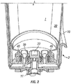
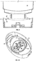
- the base unit 2 comprises a cowling 10 which forms a cup-shaped housing surrounding a significant portion of the refill to protect and support it.
- a spigot 11 projects through the base of the cowling 10 and is sealed to the cowling 10 by an O-ring seal 12.
- the spigot has a plurality of castellations 13 in its top surface.
- a second O-ring seal 14 surrounds the spigot 11 beneath the castellations 13.
- the refill 1 comprises a bottle 20 to which a cap 21 is fixed.
- the bottle 20 has a neck 22 which fits over and seals with an annular flange 23 within the cap 21.
- the cap 21 has an upwardly depending skirt 24 (when in the inverted orientation shown in the drawings) which forms the outer surface of the cap.
- Working inwardly from the skirt 24, the next feature of the cap is an outer annular wall 25 which is generally co-axial with the skirt 24.
- the outer annular wall 25 consists of a pair of retaining members 26 and a pair of support members 27 which alternate with one another and each extend for approximately a quarter of the circle as shown in Figs. 5 , 6 , 8 and 10 .
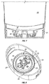
- the profile of the support members 27 is as shown in Fig. 2 . These members extend directly up from the lower wall of the cap, are parallel sided and have an inclined upper surface 28.
- the profile of the retaining members 26 is shown in Figs. 7 and 9 . Unlike the support members 27, these are not fixed to the wall of the cap. Instead, they are fixed at either end to the support members 27 by frangible members 29 as best shown in Figs. 6 and 8 .
- the retaining members 26 are parallel sided and have an inclined upper surface 35 as shown in Figs . 7 and 9 .
- the neck 22 of the bottle has an inclined outer surface 36 which is complimentary to the inclined surfaces 28 and 35 of the annular wall 25. Behind the inclined outer surface 36 is a shoulder 37 which faces the main body of the bottle 20. This inclined outer surface 36 and shoulder 37 is only present in the vicinity of the retaining members 26 and not in the vicinity of the support members 27. Adjacent to the support members 27, the neck 22 has a parallel sided configuration as shown in Fig. 2 .
- the bottle 20 In order to insert the bottle 20 into the cap 21, the bottle 20 is pushed down with its neck fitting over the annular flange 23.
- the inclined outer surface 36 of the bottle co-operates with the inclined surfaces 28, 35 to displace the retaining members 26 radially outwardly until the shoulder 37 snaps into place behind the retaining members 26 as shown in Fig. 7 .
- the shoulders 37 bear against the retaining members 26, thereby breaking frangible members 29 so that the retaining members 26 become detached from the cap 21 as shown in Figs. 9 and 10 . Once this has happened, it is no longer possible to retain the cap on a bottle, thereby preventing subsequent use of the refill 1.
- both of the retaining members 26 it is not necessary for both of the retaining members 26 to become fully detached from the lid. It is possible that only one of these becomes detached, or that one or both are simply displaced to a location at which they can no longer engage with the neck of the bottle.
- the liquid outlet from the reservoir is provided by an annular wall 30 surrounding a central opening 31.
- annular wall 30 At the top of the annular wall 30 is an inclined surface 32 (see Fig. 4 ) which provides a valve seat for outlet valve element 33.
- This is shown in the form of a U-shape cup-like member, but may equally be a solid member or a hollow ball-like member.
- the outlet valve element 33 is biased into its closed position by a plurality of biasing elements 34.
- valve element 33 are attached at their upper end towards the top of the valve element 33 and are attached at their lower ends at a location radially outward of the annular wall 30 and below the top of the annular wall 30. They are preferably formed integrally with the valve element 33.
- the cap is provided with a pair of pressure relief valves 40. Each is formed by an annular boss 41 integral with the cap 21.
- a pressure relief valve element 42 is seated on the top of the annular boss 41 and is biased in place by a pair of biasing elements 43 (as shown, for example, in Fig. 5 ) .
- the biasing force is such that, under normal conditions, the pressure relief valve element 42 forms an air tight seal on the boss 41.
- the pressure differential across the relief valve element 42 is sufficient to overcome the force exerted by biasing elements 43 and to allow air into the bottle 20. This reduces the pressure differential thereby restoring the air tight seal without leakage of fluid.
- Each pressure relief valve 40 is surrounded by an annular barrier 44 which extends axially to a level axially above the level of the top of the annular wall 30.
- annular barrier 44 which extends axially to a level axially above the level of the top of the annular wall 30.
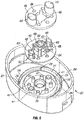
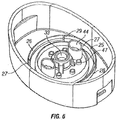
- the assembly is a three-part structure consisting of the cap 21, a valve plate 45 and a fixing plate 46.
- the cap has a number of moulded features including the annular flange 23, annular wall 25 and annular bosses 41.
- the cap 21 has a plurality of fixing posts 47.
- the valve plate 45 is an elastomeric material and is integrally formed with the valve element 33, biasing elements 34, relief valve element 42 and biasing elements 43.
- the valve plate has a plurality of locating holes 48 which correspond to the fixing posts 47.
- the fixing plate 46 is made of a rigid plastics material and is integrally formed with the annular barrier 44. As with the valve plate 45, the fixing plate 46 is also provided with a plurality of locating holes 49 which correspond to the fixing posts 47.
- the three components are placed on top of one another as shown in Fig. 6 with the fixing posts entering the locating holes to ensure that the components are correctly aligned. Heat or adhesive is then applied to the top of the fixing posts 47 to secure the fixing posts to the fixing plate 46.
- the elastomeric valve plate 45 is thereby sandwiched between the cap 21 and fixing plate 46 which holds the valve elements 33 and 42 in position.
- the structure of the outlet valve element 33 in the second example is essentially the same as the first example, and will not be described again in relation to the second example .
- the cap 21 is integrally molded with a number of features, such as the annular walls 25 and 30 and a conical part 50 of the pressure relief valve which will be described below.
- a resilient lip 53 (described in more detail below) for the pressure relief valve is provided integrally molded with the valve plate 45.
- the fixing plate 46 is also provided with a shield 57 for the relief valve. This is equivalent to the barrier 44 in Fig. 2 , but only extends around the side of the relief valve facing the outlet valve element 33.
- the barrier 44 and shield 57 could be used interchangeably in the two examples.
- the cap assembly is assembled in the same manner as in the first example.
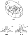
- the pressure relief valve 60 is illustrated in Figs. 13 and 14 .
- the valve has the conical part 50 which is an integral part of the cap 21 as mentioned above.
- the conical part 50 is a cylindrical post 61.
- the resilient lip 53 is effectively a hollow frustoconical extension of the valve plate 52 of resilient material which extends along the conical part 50 from which it diverges slightly and is a tight fit against the post 61.
- At least one air inlet 62 (also shown in Fig. 11 ) passes through the wall of the conical part 50 and is normally covered by the resilient lip 53 as shown in Fig. 11 .
- the pressure in the bottle 20 falls as liquid is emptied the pressure differential across the resilient lip 53 will eventually become sufficient to displace the lip 53 to a sufficient degree to allow air A into the bottle 20 as shown by the arrows in Fig. 8 .
- the degree to which the resilient lip 53 lifts from the conical element 50 has been exaggerated in Fig. 8 and that, in practice, this will be almost imperceptible .
- the resilient lip 53 may seal against the conical part 50.
- the lip will not diverge from the conical part as shown. Instead, it would actually have an angle of incline less than the angle of the conical part 50 so as to be naturally biased onto the conical part.
- the outlet valve element 33' is shaped differently. In this case, there is a reduced diameter portion 60 which fits within the annular wall 30 when the valve is closed to assist the sealing to the annular wall.
- the pair of pressure relief valves 40 have been replaced by a single conventional umbrella valve 61.
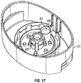
- the retaining members 26 with their frangible members 29 have been replaced by a plurality of intermittent shoulders 62 which, as shown in Fig. 18 engage with complementary shoulders 63 on the neck of the bottle 20. Inward deflection of the neck of the bottle is prevented by a flange 64. Once in the Fig. 18 position, the engagement between the shoulders is strong enough to prevent the cap from being removed from the bottle for all practical purposes. This is facilitated by a keying arrangement 64 on the cap as shown in Figs. 16 and 17 which engages with a complementary protrusion on the bottle (not shown) to prevent relative rotation between the cap 21 and bottle 20.
- An inclination sensor means according to the invention, as well as the overall operation of inclination sensor means with respect to the position of the dispenser is discussed with reference to the following figures.
- Fig. 19 illustrates in relevant part a perspective view of a part of the interior of the base unit 2 of Fig. 1 , here taken from the opposite side of the view presented in Fig. 1 and showing in relevant part and in more detail the inclination sensor means 100.
- the inclination sensor means 100 comprises a generally tubular cavity which contains within the cavity a movable conductive element, namely a metallic ball.
- the metallic ball may freely move within the cavity between the two ends 101, 102 and further, the inclination sensor means includes one or more signal carriers (e.g., wires) (not shown) which may be used to transmit a suitable signal which can be used to initiate or halt the operation of the pump (not shown).
- signal carriers e.g., wires
- the sidewall 103 of the inclination sensor means 100 is generally tubular in shape, and a central axis or center line "C" may defined.
- the metallic ball may freely move between the two ends 101, 102, so that when the base unit 2 is moved from the generally vertical orientation a shown in Fig. 1 and in Figs. 19, 20 and inclined, the metallic ball may move to an end of the inclination sensor means 100.
- the base unit 2 is placed upon a generally horizontal planar surface, "H", which can be used to define the respective or relative orientation of the base unit 2 and any or all parts thereof.
- a degree of inclination can also be defined with respect to the generally horizontal planar surface "H", and the position of the base unit 2 as shown, is understood to be in a generally vertical orientation.
- the inclination sensor means 100 is mounted upon or through, here extending through a vertical mounting plate 105 which is generally perpendicular to the horizontal, and the center line or axis "C" of the inclination sensor means 100 is angled by an angle "B" with respect to the horizontal "H".
- the angle "B" is between 2 and 89 degrees of arc, but preferably is between 5 - 75 degrees of arc, especially preferably between 5 - 45 degrees of arc.
- the angle B is approximately 20° of arc.
- the ball When the base unit 2 is inclined in a forward direction, (represented by the arrow "F") viz, in the direction of the nozzle with respect to the balance of the base unit 2, and the base unit 2 is tilted in such a direction, by a sufficient degree of offset with respect to the horizontal, the ball may freely move to the opposite end 101 and (although not shown) come into contact with one or more suitable pads or wires, thereby closing an electrical circuit or otherwise transmitting a suitable signal to the pump or controller means of the dispenser (not shown in this figure). This is better understood with reference to the following Fig. 21 .
- Fig. 21 Depicted on Fig. 21 is a dispenser according to the invention, and relevant in particular to the embodiments according to Figures 19 and 20 in three different relative positions of inclination.
- the base unit 2 rests atop a generally planar horizontal surface H such that the base unit 2 and the dispenser are considered to be in a generally vertical orientation.
- the proximity sensor can be used to dispense a quantity of the liquid soap contained within the refill unit 1 in the manner described previously.
- the base unit 2 In the second position 202, the base unit 2 has been lifted and separated from the generally planar horizontal surface H and is inclined forwardly (in the direction of arrow 'F") by an angle "A".
- the base unit 2 is inclined by at least the angle A, which is to be understood as to be a sufficient angle in order to cause the operation of the inclination sensor means (not shown) which in turn activates the control circuit and/or pump, thereby causing a dose 206 of the liquid soap to be dispensed from the nozzle 6 of the dispenser.
- the angles A B, but preferably A ⁇ B. In such an inclined orientation the dispenser is caused or operates to deliver a metered dose of the liquid soap 6 directly into the interior of a suitable basin, or sink "S", and no activity or function of the proximity sensor is required.
- a user may conveniently lift the dispenser from a storage a resting position, such as 200 in Fig. 21 , and without engaging or operating the proximity sensor, tilt it forwardly to cause the device to dispense one or more metered doses of liquid to a sink, basin, or other receptacle which advantageously contains a quantity of water and/or dishware.
- inclination sensor means 100 is illustrated as being mounted on a vertical mounting plate 105, such is to be understood as being merely an illustrative embodiment and not to limit the scope of the invention, defined by the appended claims.
- the inclination sensor means 100 or for that matter any other device which may function as an inclination sensor means may be mounted or affixed to any part of the base unit 2 in any suitable manner.
- the inclusion of a mounting plate 105 is not required, although such provides a convenient support for mounting of the inclination sensor means 100 and the receiver 78 as depicted.
- the liquid to be dispensed from the dispenser may virtually any liquid which may be used in a cleaning, disinfecting or sanitizing treatment or processes.
- the liquid supplied by the dispenser may be used directly without further dilution, or may be diluted to form a working treatment composition, e.g., by diluting or dispersing a quantity of the liquid in a larger volume of a solvent or water, which is thereafter used.
- the liquid may be used to treat inanimate surfaces including hard surfaces as well as soft surfaces.
- Non-limiting examples of hard surfaces are generally non-porous materials such as surfaces composed of refractory materials such as: glazed and unglazed tile, brick, porcelain, ceramics as well as stone including marble, granite, and other stones surfaces; glass, metals, plastics e.g.
- Non-limiting examples of soft surfaces include generally porous materials such as carpets, rugs, upholstery, curtains and drapes, fabrics, textiles, garments, and the like.
- the liquid may also be used in topical applications, such as skin sanitization, handwash, bodywash and hair washing applications.
- the liquid or a working treatment composition may be applied directly or with the use of an ancillary article, such as a sponge, washcloth, paper towel, wipe article such as woven or nonwoven wipe, microfiber cloth, tissue or other fibrous substrate, or abrasive pad.
Landscapes
- Health & Medical Sciences (AREA)
- Public Health (AREA)
- Engineering & Computer Science (AREA)
- Mechanical Engineering (AREA)
- Containers And Packaging Bodies Having A Special Means To Remove Contents (AREA)
- Devices For Dispensing Beverages (AREA)
- Closures For Containers (AREA)
Claims (9)
- Spender, der eine Basiseinheit (2) mit einem Betätigungsmechanismus zur Ausgabe einer Flüssigkeit und eine Nachfülleinheit (1), die in einer invertierten Konfiguration mit ihrem Auslass in der untersten Position zur Zufuhr von Flüssigkeit zur Basiseinheit (2) in die Basiseinheit (2) einsetzbar ist, umfasst, wobei die Nachfülleinheit (1) eine ringförmige Wand (30) umfasst, die in die Nachfülleinheit (1) vorragt und einen Auslass aus der Nachfülleinheit (1) definiert, wobei die ringförmige Wand (30) an ihrem am weitesten innen liegenden Ende durch ein Ventilelement (33) verschließbar ist, das gegen die ringförmige Wand (30) vorgespannt ist, wobei die Basiseinheit (2) einen hohlen Zapfen (11) und eine ringförmige Dichtung (14), die den oberen Teil des Zapfens (11) umgibt und von diesem beabstandet ist, umfasst, wobei das Einführen der Nachfülleinheit (1) in die Basiseinheit (2) dazu führt, dass der Zapfen (11) in die ringförmige Wand (30) eintritt und das Ventilelement (33) dahingehend von der ringförmigen Wand weg hebt, einen Strömungspfad von der Nachfülleinheit (1) durch mindestens einen in dem oberen Teil des Zapfens (11) und/oder dem unteren Teil des Ventilelements (33) ausgebildeten Ausschnittsabschnitt und durch den hohlen Zapfen (11) zu definieren, und dass die ringförmige Dichtung (14) zwischen dem Zapfen (11) und der ringförmigen Wand (30) abdichtet, wobei die Basiseinheit (2) des Weiteren ein Näherungssensormittel und ein Neigungssensormittel (100) umfasst, dadurch gekennzeichnet, dass das Neigungssensormittel (100) das Betätigungsmittel aktiviert, wenn der Spender in einem Neigungswinkel "A" bezüglich einer vertikalen Ausrichtung des Spenders nach vorne geneigt wird, wodurch bewirkt wird, dass die Vorrichtung eine oder mehrere Dosen an Flüssigkeit aus dem Spender abgibt.
- Spender nach Anspruch 1, wobei das Ventilelement (33) durch mindestens ein elastisches Glied gegen die ringförmige Wand (30) vorgespannt wird.
- Spender nach Anspruch 2, wobei das mindestens eine elastische Glied an einem Ende mit dem Ventilelement (33) und an dem anderen Ende an einer Stelle, die sich von dem am weitesten innen liegenden Ende der ringförmigen Wand (30) radial nach außen hin und darunter befindet, verbunden ist,
wobei das oder jedes elastische Glied so konfiguriert ist, dass, wenn das Ventilelement (33) von der ringförmigen Wand (30) weg gehoben wird, ein Strömungspfad zwischen dem Ventilelement (33) und der ringförmigen Wand (30) vorliegt. - Spender nach Anspruch 2 oder 3, wobei es mehrere elastische Elemente mit Lücken dazwischen zur Bereitstellung des Strömungspfads gibt.
- Spender nach Anspruch 2 oder Anspruch 4, wobei das Ventilelement (33) integral mit dem oder jedem elastischen Glied hergestellt ist.
- Spender nach Anspruch 5, wobei sich das oder jedes elastische Glied in eine umgebende Ventilplatte (45) erstreckt, die an dem Deckel der Nachfülleinheit (1) gesichert ist.
- Spender nach Anspruch 6, wobei die Ventilplatte (45) zwischen dem Deckel und einer Fixierungsplatte (46) angeordnet ist.
- Spender nach Anspruch 7, wobei eine oder mehrere Fixierungssäulen (47) zur Positionierung der verschiedenen Elemente bezüglich einander in dem Deckel oder der Ventilplatte (45) oder der Fixierungsplatte (46) vorgesehen sind.
- Spender nach einem der vorhergehenden Ansprüche, wobei die Nachfülleinheit (1) mit einer Flüssigkeit gefüllt ist, die eine Viskosität aufweist, die über der von Wasser liegt.
Applications Claiming Priority (2)
| Application Number | Priority Date | Filing Date | Title |
|---|---|---|---|
| GB201202578A GB201202578D0 (en) | 2012-02-15 | 2012-02-15 | Dispenser and refill unit and dispensing methods |
| PCT/GB2013/050272 WO2013121177A2 (en) | 2012-02-15 | 2013-02-06 | Dispenser and refill unit and dispensing methods |
Publications (2)
| Publication Number | Publication Date |
|---|---|
| EP2814367A2 EP2814367A2 (de) | 2014-12-24 |
| EP2814367B1 true EP2814367B1 (de) | 2017-07-12 |
Family
ID=45930123
Family Applications (1)
| Application Number | Title | Priority Date | Filing Date |
|---|---|---|---|
| EP13705001.9A Not-in-force EP2814367B1 (de) | 2012-02-15 | 2013-02-06 | Spender mit einem neigungssensor |
Country Status (4)
| Country | Link |
|---|---|
| US (1) | US9504360B2 (de) |
| EP (1) | EP2814367B1 (de) |
| GB (1) | GB201202578D0 (de) |
| WO (1) | WO2013121177A2 (de) |
Families Citing this family (34)
| Publication number | Priority date | Publication date | Assignee | Title |
|---|---|---|---|---|
| ES2851154T3 (es) * | 2010-06-10 | 2021-09-03 | Fern Innovations Ip Llc | Distribuidor |
| US10433372B2 (en) | 2013-12-20 | 2019-10-01 | Toaster Labs, Inc. | Portable fluid warming device |
| US9801505B2 (en) | 2013-12-20 | 2017-10-31 | Toaster Labs, Inc. | Automatic fluid dispenser |
| US9974416B2 (en) | 2013-12-20 | 2018-05-22 | Toaster Labs, Inc. | Automatic heated fluid dispenser |
| US10098510B2 (en) | 2013-12-20 | 2018-10-16 | Toaster Loabs, Inc. | Pneumatically driven fluid dispenser |
| US10144032B2 (en) | 2013-12-20 | 2018-12-04 | Toaster Labs, Inc. | Inductively heatable fluid reservoir |
| US10189038B2 (en) | 2013-12-20 | 2019-01-29 | Toaster Labs, Inc. | Inductively heatable fluid reservoir for various fluid types |
| CA2940525C (en) | 2014-02-24 | 2023-01-31 | Gojo Industries, Inc. | Vented non-collapsing containers, refillable refill containers, dispensers and refill units |
| US20160060092A1 (en) * | 2014-08-27 | 2016-03-03 | Deepak Haricharan Vittaldevara | Interactive electronic fluid dispensing apparatus |
| US9884336B2 (en) * | 2014-10-10 | 2018-02-06 | The Procter & Gamble Company | Multifunctional dispensing device for dispensing fluid compositions |
| US11076986B2 (en) | 2015-05-12 | 2021-08-03 | Ikem C Ajaelo | Electronic drop dispensing device and method of operation thereof |
| US9949599B2 (en) * | 2015-06-17 | 2018-04-24 | Gojo Industries, Inc. | Vent valves and refill units with vent valves for use with inverted non-collapsing containers |
| NL2017109B1 (en) | 2016-07-05 | 2018-01-12 | Heineken Supply Chain Bv | Beverage dispensing assembly and beverage container |
| NL2018955B1 (en) * | 2017-05-19 | 2018-11-28 | Heineken Supply Chain Bv | Beverage dispensing assembly and beverage container |
| NL2018956B1 (en) | 2017-05-19 | 2018-11-28 | Heineken Supply Chain Bv | Beverage dispensing assembly and beverage container |
| BR112020022305B1 (pt) * | 2018-06-04 | 2023-11-07 | Unilever Ip Holdings B.V | Composição de cuidados pessoais e método de preservação de composições |
| CN108888152A (zh) * | 2018-07-10 | 2018-11-27 | 江苏浙泰机电科技有限公司 | 一种专用液供应装置 |
| US11659812B2 (en) | 2018-09-19 | 2023-05-30 | Lg Electronics Inc. | Liquid dispenser for animals |
| US11653627B2 (en) | 2018-09-19 | 2023-05-23 | Lg Electronics Inc. | Liquid dispenser for animals |
| US11871732B2 (en) | 2018-09-19 | 2024-01-16 | Lg Electronics Inc. | Liquid dispenser for animals |
| US11160250B2 (en) | 2018-09-19 | 2021-11-02 | Lg Electronics Inc. | Liquid dispenser for animals |
| US11527906B2 (en) | 2018-09-19 | 2022-12-13 | Lg Electronics Inc. | Liquid dispenser for animals |
| US11659813B2 (en) | 2018-09-19 | 2023-05-30 | Lg Electronics Inc. | Liquid dispenser for animals |
| US11596127B2 (en) | 2018-09-19 | 2023-03-07 | Lg Electronics Inc. | Liquid dispenser for animals |
| US11565202B2 (en) | 2018-09-19 | 2023-01-31 | Lg Electronics Inc. | Liquid dispenser for animals |
| US11191252B2 (en) * | 2018-09-19 | 2021-12-07 | Lg Electronics Inc. | Liquid dispenser for animals |
| US11154034B2 (en) | 2018-09-19 | 2021-10-26 | Lg Electronics Inc. | Liquid dispenser having sensors |
| KR102849409B1 (ko) | 2018-09-19 | 2025-08-22 | 엘지전자 주식회사 | 반려동물 급수기 |
| US11590438B2 (en) | 2018-09-19 | 2023-02-28 | Lg Electronics Inc. | Liquid dispenser for animals |
| US11771058B2 (en) | 2018-09-19 | 2023-10-03 | Lg Electronics Inc. | Liquid dispenser for animals |
| JP6935823B2 (ja) * | 2020-02-28 | 2021-09-15 | 東洋製罐株式会社 | 閉塞装置および軟包装容器 |
| ES2882950A1 (es) * | 2020-06-03 | 2021-12-03 | Martinez Chazarra Maria Jose | Estación de desinfección de manos mediante líquidos o geles sanitarios |
| US11800957B2 (en) | 2021-03-12 | 2023-10-31 | Salto, Llc | Amenity fluid dispensing system |
| WO2023200629A1 (en) * | 2022-04-14 | 2023-10-19 | Gojo Industries, Inc. | Table top dispensers with anti-refill and anti-tampering mechanisms |
Citations (2)
| Publication number | Priority date | Publication date | Assignee | Title |
|---|---|---|---|---|
| US20060249530A1 (en) * | 2005-05-06 | 2006-11-09 | Allure Home Creations Co., Inc. | Dispenser with sound and motion |
| US20100117836A1 (en) * | 2007-03-30 | 2010-05-13 | Toronto Rehabilitation Institute | Hand hygiene compliance system |
Family Cites Families (6)
| Publication number | Priority date | Publication date | Assignee | Title |
|---|---|---|---|---|
| US4736871A (en) | 1986-11-19 | 1988-04-12 | Luciani Dorian E | Liquid measuring dispenser |
| US8387827B2 (en) | 2008-03-24 | 2013-03-05 | S.C. Johnson & Son, Inc. | Volatile material dispenser |
| PT104086B (pt) | 2008-06-05 | 2011-07-22 | Blueworks Medical Expert Diagnostics Lda | Processo para monitorização do sucesso da aplicação de um fluido a um alvo biológico não estático e sistema para sua execução |
| GB0820978D0 (en) * | 2008-11-17 | 2008-12-24 | Reckitt & Colman Overseas | A relief valve |
| GB0820981D0 (en) * | 2008-11-17 | 2008-12-24 | Reckitt & Colman Overseas | Dispenser and refill unit |
| GB201018005D0 (en) * | 2010-10-26 | 2010-12-08 | Reckitt Benckiser Inc | Dispenser for a foaming liquid composition |
-
2012
- 2012-02-15 GB GB201202578A patent/GB201202578D0/en not_active Ceased
-
2013
- 2013-02-06 EP EP13705001.9A patent/EP2814367B1/de not_active Not-in-force
- 2013-02-06 US US14/373,177 patent/US9504360B2/en active Active
- 2013-02-06 WO PCT/GB2013/050272 patent/WO2013121177A2/en not_active Ceased
Patent Citations (2)
| Publication number | Priority date | Publication date | Assignee | Title |
|---|---|---|---|---|
| US20060249530A1 (en) * | 2005-05-06 | 2006-11-09 | Allure Home Creations Co., Inc. | Dispenser with sound and motion |
| US20100117836A1 (en) * | 2007-03-30 | 2010-05-13 | Toronto Rehabilitation Institute | Hand hygiene compliance system |
Also Published As
| Publication number | Publication date |
|---|---|
| GB201202578D0 (en) | 2012-03-28 |
| EP2814367A2 (de) | 2014-12-24 |
| US20140353335A1 (en) | 2014-12-04 |
| WO2013121177A3 (en) | 2013-12-05 |
| WO2013121177A2 (en) | 2013-08-22 |
| US9504360B2 (en) | 2016-11-29 |
Similar Documents
| Publication | Publication Date | Title |
|---|---|---|
| EP2814367B1 (de) | Spender mit einem neigungssensor | |
| AU2009315391B2 (en) | Dispenser and refill unit | |
| AU2009315390B2 (en) | A bottle with a tamper-proof cap | |
| AU2009315386B2 (en) | A relief valve | |
| EP3119528B1 (de) | Spendervorrichtung | |
| EP2632817B1 (de) | Behälter mit zerbrechlicher geräteschnittstelle | |
| WO2012123763A2 (en) | Dispenser and refill unit | |
| HK1163045B (en) | Dispenser and refill unit | |
| HK1163036B (en) | A relief valve,a container having the relief valve and a refill unit |
Legal Events
| Date | Code | Title | Description |
|---|---|---|---|
| PUAI | Public reference made under article 153(3) epc to a published international application that has entered the european phase |
Free format text: ORIGINAL CODE: 0009012 |
|
| 17P | Request for examination filed |
Effective date: 20140808 |
|
| AK | Designated contracting states |
Kind code of ref document: A2 Designated state(s): AL AT BE BG CH CY CZ DE DK EE ES FI FR GB GR HR HU IE IS IT LI LT LU LV MC MK MT NL NO PL PT RO RS SE SI SK SM TR |
|
| AX | Request for extension of the european patent |
Extension state: BA ME |
|
| DAX | Request for extension of the european patent (deleted) | ||
| 17Q | First examination report despatched |
Effective date: 20160414 |
|
| GRAP | Despatch of communication of intention to grant a patent |
Free format text: ORIGINAL CODE: EPIDOSNIGR1 |
|
| INTG | Intention to grant announced |
Effective date: 20170308 |
|
| GRAS | Grant fee paid |
Free format text: ORIGINAL CODE: EPIDOSNIGR3 |
|
| GRAA | (expected) grant |
Free format text: ORIGINAL CODE: 0009210 |
|
| AK | Designated contracting states |
Kind code of ref document: B1 Designated state(s): AL AT BE BG CH CY CZ DE DK EE ES FI FR GB GR HR HU IE IS IT LI LT LU LV MC MK MT NL NO PL PT RO RS SE SI SK SM TR |
|
| REG | Reference to a national code |
Ref country code: GB Ref legal event code: FG4D |
|
| REG | Reference to a national code |
Ref country code: CH Ref legal event code: EP |
|
| REG | Reference to a national code |
Ref country code: AT Ref legal event code: REF Ref document number: 907542 Country of ref document: AT Kind code of ref document: T Effective date: 20170715 |
|
| REG | Reference to a national code |
Ref country code: IE Ref legal event code: FG4D |
|
| REG | Reference to a national code |
Ref country code: DE Ref legal event code: R096 Ref document number: 602013023359 Country of ref document: DE |
|
| REG | Reference to a national code |
Ref country code: NL Ref legal event code: MP Effective date: 20170712 |
|
| REG | Reference to a national code |
Ref country code: LT Ref legal event code: MG4D |
|
| REG | Reference to a national code |
Ref country code: AT Ref legal event code: MK05 Ref document number: 907542 Country of ref document: AT Kind code of ref document: T Effective date: 20170712 |
|
| REG | Reference to a national code |
Ref country code: FR Ref legal event code: PLFP Year of fee payment: 6 |
|
| PG25 | Lapsed in a contracting state [announced via postgrant information from national office to epo] |
Ref country code: HR Free format text: LAPSE BECAUSE OF FAILURE TO SUBMIT A TRANSLATION OF THE DESCRIPTION OR TO PAY THE FEE WITHIN THE PRESCRIBED TIME-LIMIT Effective date: 20170712 Ref country code: SE Free format text: LAPSE BECAUSE OF FAILURE TO SUBMIT A TRANSLATION OF THE DESCRIPTION OR TO PAY THE FEE WITHIN THE PRESCRIBED TIME-LIMIT Effective date: 20170712 Ref country code: LT Free format text: LAPSE BECAUSE OF FAILURE TO SUBMIT A TRANSLATION OF THE DESCRIPTION OR TO PAY THE FEE WITHIN THE PRESCRIBED TIME-LIMIT Effective date: 20170712 Ref country code: AT Free format text: LAPSE BECAUSE OF FAILURE TO SUBMIT A TRANSLATION OF THE DESCRIPTION OR TO PAY THE FEE WITHIN THE PRESCRIBED TIME-LIMIT Effective date: 20170712 Ref country code: NL Free format text: LAPSE BECAUSE OF FAILURE TO SUBMIT A TRANSLATION OF THE DESCRIPTION OR TO PAY THE FEE WITHIN THE PRESCRIBED TIME-LIMIT Effective date: 20170712 Ref country code: NO Free format text: LAPSE BECAUSE OF FAILURE TO SUBMIT A TRANSLATION OF THE DESCRIPTION OR TO PAY THE FEE WITHIN THE PRESCRIBED TIME-LIMIT Effective date: 20171012 Ref country code: FI Free format text: LAPSE BECAUSE OF FAILURE TO SUBMIT A TRANSLATION OF THE DESCRIPTION OR TO PAY THE FEE WITHIN THE PRESCRIBED TIME-LIMIT Effective date: 20170712 |
|
| PG25 | Lapsed in a contracting state [announced via postgrant information from national office to epo] |
Ref country code: RS Free format text: LAPSE BECAUSE OF FAILURE TO SUBMIT A TRANSLATION OF THE DESCRIPTION OR TO PAY THE FEE WITHIN THE PRESCRIBED TIME-LIMIT Effective date: 20170712 Ref country code: PL Free format text: LAPSE BECAUSE OF FAILURE TO SUBMIT A TRANSLATION OF THE DESCRIPTION OR TO PAY THE FEE WITHIN THE PRESCRIBED TIME-LIMIT Effective date: 20170712 Ref country code: LV Free format text: LAPSE BECAUSE OF FAILURE TO SUBMIT A TRANSLATION OF THE DESCRIPTION OR TO PAY THE FEE WITHIN THE PRESCRIBED TIME-LIMIT Effective date: 20170712 Ref country code: GR Free format text: LAPSE BECAUSE OF FAILURE TO SUBMIT A TRANSLATION OF THE DESCRIPTION OR TO PAY THE FEE WITHIN THE PRESCRIBED TIME-LIMIT Effective date: 20171013 Ref country code: BG Free format text: LAPSE BECAUSE OF FAILURE TO SUBMIT A TRANSLATION OF THE DESCRIPTION OR TO PAY THE FEE WITHIN THE PRESCRIBED TIME-LIMIT Effective date: 20171012 Ref country code: IS Free format text: LAPSE BECAUSE OF FAILURE TO SUBMIT A TRANSLATION OF THE DESCRIPTION OR TO PAY THE FEE WITHIN THE PRESCRIBED TIME-LIMIT Effective date: 20171112 Ref country code: ES Free format text: LAPSE BECAUSE OF FAILURE TO SUBMIT A TRANSLATION OF THE DESCRIPTION OR TO PAY THE FEE WITHIN THE PRESCRIBED TIME-LIMIT Effective date: 20170712 |
|
| REG | Reference to a national code |
Ref country code: DE Ref legal event code: R097 Ref document number: 602013023359 Country of ref document: DE |
|
| PG25 | Lapsed in a contracting state [announced via postgrant information from national office to epo] |
Ref country code: CZ Free format text: LAPSE BECAUSE OF FAILURE TO SUBMIT A TRANSLATION OF THE DESCRIPTION OR TO PAY THE FEE WITHIN THE PRESCRIBED TIME-LIMIT Effective date: 20170712 Ref country code: DK Free format text: LAPSE BECAUSE OF FAILURE TO SUBMIT A TRANSLATION OF THE DESCRIPTION OR TO PAY THE FEE WITHIN THE PRESCRIBED TIME-LIMIT Effective date: 20170712 Ref country code: RO Free format text: LAPSE BECAUSE OF FAILURE TO SUBMIT A TRANSLATION OF THE DESCRIPTION OR TO PAY THE FEE WITHIN THE PRESCRIBED TIME-LIMIT Effective date: 20170712 |
|
| PLBE | No opposition filed within time limit |
Free format text: ORIGINAL CODE: 0009261 |
|
| STAA | Information on the status of an ep patent application or granted ep patent |
Free format text: STATUS: NO OPPOSITION FILED WITHIN TIME LIMIT |
|
| PG25 | Lapsed in a contracting state [announced via postgrant information from national office to epo] |
Ref country code: SK Free format text: LAPSE BECAUSE OF FAILURE TO SUBMIT A TRANSLATION OF THE DESCRIPTION OR TO PAY THE FEE WITHIN THE PRESCRIBED TIME-LIMIT Effective date: 20170712 Ref country code: IT Free format text: LAPSE BECAUSE OF FAILURE TO SUBMIT A TRANSLATION OF THE DESCRIPTION OR TO PAY THE FEE WITHIN THE PRESCRIBED TIME-LIMIT Effective date: 20170712 Ref country code: SM Free format text: LAPSE BECAUSE OF FAILURE TO SUBMIT A TRANSLATION OF THE DESCRIPTION OR TO PAY THE FEE WITHIN THE PRESCRIBED TIME-LIMIT Effective date: 20170712 Ref country code: EE Free format text: LAPSE BECAUSE OF FAILURE TO SUBMIT A TRANSLATION OF THE DESCRIPTION OR TO PAY THE FEE WITHIN THE PRESCRIBED TIME-LIMIT Effective date: 20170712 |
|
| 26N | No opposition filed |
Effective date: 20180413 |
|
| PG25 | Lapsed in a contracting state [announced via postgrant information from national office to epo] |
Ref country code: SI Free format text: LAPSE BECAUSE OF FAILURE TO SUBMIT A TRANSLATION OF THE DESCRIPTION OR TO PAY THE FEE WITHIN THE PRESCRIBED TIME-LIMIT Effective date: 20170712 |
|
| REG | Reference to a national code |
Ref country code: CH Ref legal event code: PL |
|
| PG25 | Lapsed in a contracting state [announced via postgrant information from national office to epo] |
Ref country code: MC Free format text: LAPSE BECAUSE OF FAILURE TO SUBMIT A TRANSLATION OF THE DESCRIPTION OR TO PAY THE FEE WITHIN THE PRESCRIBED TIME-LIMIT Effective date: 20170712 |
|
| REG | Reference to a national code |
Ref country code: IE Ref legal event code: MM4A |
|
| REG | Reference to a national code |
Ref country code: BE Ref legal event code: MM Effective date: 20180228 |
|
| PG25 | Lapsed in a contracting state [announced via postgrant information from national office to epo] |
Ref country code: CH Free format text: LAPSE BECAUSE OF NON-PAYMENT OF DUE FEES Effective date: 20180228 Ref country code: LU Free format text: LAPSE BECAUSE OF NON-PAYMENT OF DUE FEES Effective date: 20180206 Ref country code: LI Free format text: LAPSE BECAUSE OF NON-PAYMENT OF DUE FEES Effective date: 20180228 |
|
| PG25 | Lapsed in a contracting state [announced via postgrant information from national office to epo] |
Ref country code: IE Free format text: LAPSE BECAUSE OF NON-PAYMENT OF DUE FEES Effective date: 20180206 |
|
| PG25 | Lapsed in a contracting state [announced via postgrant information from national office to epo] |
Ref country code: BE Free format text: LAPSE BECAUSE OF NON-PAYMENT OF DUE FEES Effective date: 20180228 |
|
| PG25 | Lapsed in a contracting state [announced via postgrant information from national office to epo] |
Ref country code: MT Free format text: LAPSE BECAUSE OF NON-PAYMENT OF DUE FEES Effective date: 20180206 |
|
| PG25 | Lapsed in a contracting state [announced via postgrant information from national office to epo] |
Ref country code: TR Free format text: LAPSE BECAUSE OF FAILURE TO SUBMIT A TRANSLATION OF THE DESCRIPTION OR TO PAY THE FEE WITHIN THE PRESCRIBED TIME-LIMIT Effective date: 20170712 |
|
| PG25 | Lapsed in a contracting state [announced via postgrant information from national office to epo] |
Ref country code: HU Free format text: LAPSE BECAUSE OF FAILURE TO SUBMIT A TRANSLATION OF THE DESCRIPTION OR TO PAY THE FEE WITHIN THE PRESCRIBED TIME-LIMIT; INVALID AB INITIO Effective date: 20130206 Ref country code: PT Free format text: LAPSE BECAUSE OF FAILURE TO SUBMIT A TRANSLATION OF THE DESCRIPTION OR TO PAY THE FEE WITHIN THE PRESCRIBED TIME-LIMIT Effective date: 20170712 |
|
| PG25 | Lapsed in a contracting state [announced via postgrant information from national office to epo] |
Ref country code: CY Free format text: LAPSE BECAUSE OF FAILURE TO SUBMIT A TRANSLATION OF THE DESCRIPTION OR TO PAY THE FEE WITHIN THE PRESCRIBED TIME-LIMIT Effective date: 20170712 Ref country code: MK Free format text: LAPSE BECAUSE OF NON-PAYMENT OF DUE FEES Effective date: 20170712 |
|
| PG25 | Lapsed in a contracting state [announced via postgrant information from national office to epo] |
Ref country code: AL Free format text: LAPSE BECAUSE OF FAILURE TO SUBMIT A TRANSLATION OF THE DESCRIPTION OR TO PAY THE FEE WITHIN THE PRESCRIBED TIME-LIMIT Effective date: 20170712 |
|
| P01 | Opt-out of the competence of the unified patent court (upc) registered |
Effective date: 20230513 |
|
| PGFP | Annual fee paid to national office [announced via postgrant information from national office to epo] |
Ref country code: GB Payment date: 20231214 Year of fee payment: 12 |
|
| PGFP | Annual fee paid to national office [announced via postgrant information from national office to epo] |
Ref country code: FR Payment date: 20231212 Year of fee payment: 12 |
|
| PGFP | Annual fee paid to national office [announced via postgrant information from national office to epo] |
Ref country code: DE Payment date: 20231212 Year of fee payment: 12 |
|
| REG | Reference to a national code |
Ref country code: DE Ref legal event code: R119 Ref document number: 602013023359 Country of ref document: DE |
|
| GBPC | Gb: european patent ceased through non-payment of renewal fee |
Effective date: 20250206 |
|
| PG25 | Lapsed in a contracting state [announced via postgrant information from national office to epo] |
Ref country code: DE Free format text: LAPSE BECAUSE OF NON-PAYMENT OF DUE FEES Effective date: 20250902 |
|
| PG25 | Lapsed in a contracting state [announced via postgrant information from national office to epo] |
Ref country code: GB Free format text: LAPSE BECAUSE OF NON-PAYMENT OF DUE FEES Effective date: 20250206 |
|
| PG25 | Lapsed in a contracting state [announced via postgrant information from national office to epo] |
Ref country code: FR Free format text: LAPSE BECAUSE OF NON-PAYMENT OF DUE FEES Effective date: 20250228 |