EP2632602B1 - Schmutzpartikel-zyklonabscheider - Google Patents
Schmutzpartikel-zyklonabscheider Download PDFInfo
- Publication number
- EP2632602B1 EP2632602B1 EP11768264.1A EP11768264A EP2632602B1 EP 2632602 B1 EP2632602 B1 EP 2632602B1 EP 11768264 A EP11768264 A EP 11768264A EP 2632602 B1 EP2632602 B1 EP 2632602B1
- Authority
- EP
- European Patent Office
- Prior art keywords
- tube
- water
- exterior
- housing
- interior
- Prior art date
- Legal status (The legal status is an assumption and is not a legal conclusion. Google has not performed a legal analysis and makes no representation as to the accuracy of the status listed.)
- Active
Links
Images


Classifications
-
- B—PERFORMING OPERATIONS; TRANSPORTING
- B04—CENTRIFUGAL APPARATUS OR MACHINES FOR CARRYING-OUT PHYSICAL OR CHEMICAL PROCESSES
- B04C—APPARATUS USING FREE VORTEX FLOW, e.g. CYCLONES
- B04C5/00—Apparatus in which the axial direction of the vortex is reversed
- B04C5/02—Construction of inlets by which the vortex flow is generated, e.g. tangential admission, the fluid flow being forced to follow a downward path by spirally wound bulkheads, or with slightly downwardly-directed tangential admission
- B04C5/04—Tangential inlets
-
- B—PERFORMING OPERATIONS; TRANSPORTING
- B04—CENTRIFUGAL APPARATUS OR MACHINES FOR CARRYING-OUT PHYSICAL OR CHEMICAL PROCESSES
- B04C—APPARATUS USING FREE VORTEX FLOW, e.g. CYCLONES
- B04C5/00—Apparatus in which the axial direction of the vortex is reversed
- B04C5/08—Vortex chamber constructions
- B04C5/103—Bodies or members, e.g. bulkheads, guides, in the vortex chamber
-
- B—PERFORMING OPERATIONS; TRANSPORTING
- B04—CENTRIFUGAL APPARATUS OR MACHINES FOR CARRYING-OUT PHYSICAL OR CHEMICAL PROCESSES
- B04C—APPARATUS USING FREE VORTEX FLOW, e.g. CYCLONES
- B04C5/00—Apparatus in which the axial direction of the vortex is reversed
- B04C5/12—Construction of the overflow ducting, e.g. diffusing or spiral exits
- B04C5/13—Construction of the overflow ducting, e.g. diffusing or spiral exits formed as a vortex finder and extending into the vortex chamber; Discharge from vortex finder otherwise than at the top of the cyclone; Devices for controlling the overflow
-
- C—CHEMISTRY; METALLURGY
- C02—TREATMENT OF WATER, WASTE WATER, SEWAGE, OR SLUDGE
- C02F—TREATMENT OF WATER, WASTE WATER, SEWAGE, OR SLUDGE
- C02F1/00—Treatment of water, waste water, or sewage
- C02F1/38—Treatment of water, waste water, or sewage by centrifugal separation
-
- C—CHEMISTRY; METALLURGY
- C02—TREATMENT OF WATER, WASTE WATER, SEWAGE, OR SLUDGE
- C02F—TREATMENT OF WATER, WASTE WATER, SEWAGE, OR SLUDGE
- C02F2103/00—Nature of the water, waste water, sewage or sludge to be treated
- C02F2103/42—Nature of the water, waste water, sewage or sludge to be treated from bathing facilities, e.g. swimming pools
Definitions
- This invention relates to particulate filters and more particularly, although not exclusively, to filters of leaves and other debris frequently encountered during cleaning of swimming pools and spas.
- U.S. Patent No. 5,269,913 to Atkins details exemplary debris traps for use with automatic swimming pool cleaners ("APCs").
- APCs automatic swimming pool cleaners
- a generally cylindrical filter suspended within a housing Attached to the housing may be a lid having a conduit with an inlet and an outlet and, at its midpoint, a downspout extending perpendicularly therefrom.
- the downspout prevents direct fluid flow through the conduit but is open to the inlet, penetrates the filter, and terminates in an open end within the filter.
- Water and debris entering the inlet are directed downward into the interior of the filter by the perpendicular tube.
- the filter includes multiple cyclones as well as "a sediment bowl with a hemispherical bottom and a sump therein for collecting sediment, a cylindrical cyclone housing disposed above and sealingly connected to the sediment bowl, a removable and replaceable cyclone cartridge inserted into the cyclone housing, a diffuser plate sealingly connected to the cyclone cartridge and cyclone housing, a fluid inlet for introducing fluid into the cyclone housing, and a fluid outlet for discharging fluid from the cyclone housing.”
- Tandon, p. 2, ⁇ 0018 "As sediment is removed from the fluid in each cyclone, it is separated out and delivered down into the sediment bowl sump, while the fluid is directed upwardly and out to the fluid outlet.” See id., Abstract.
- Filters of the Tandon application are designed to connect to outlets of fluid pumps and remove (i.e. pre-filter) fine particulates from water exiting a pump before the water enters a standard pool filter. As configured, the filters would not operate to separate leaves or other large debris from the water. Such would be true even if the (small) cyclones were scaled, although no suggestion of such scaling exists in the Tandon application. It thus is an optional, non-exclusive object of the present invention to provide filters and methods of filtering fluids.
- an optional, non-exclusive object of the present invention to provide a filter whose perforated tube defines an interior region forming part of the primary fluid flow path and that is in fluid communication with an outlet. It is yet another optional, non-exclusive object of the present invention to provide filters configured to impart spinning, spiral motion to entering fluid, with such motion (together with gravity in certain circumstances) overcoming, at least for some leaves, forces tending to attract the leaves to the perforated tube.
- the present invention provides alternate filters and methods of filtering debris from fluid. Designed principally (although not necessarily exclusively) to be connected to an inlet of a fluid pump, the invention allows separation of debris from fluid flowing to the pump. Further, debris separation may occur outside the primary fluid flow path.
- the invention is especially useful as part of a system for cleaning circulating water of a swimming pool or spa.
- Leaves in particular, present significant problems for existing cleaning systems, as their relatively large surface areas, relatively light dry weights, and saturated specific gravities similar to that of water make them difficult to separate from the water without degrading performance of the system.
- conventional cyclonic filters would perform poorly in filtering leaves entrained in water, as the attraction force to the primary flow due to their large surface areas will exceed that of the centrifugal force generated, precluding their separation from the water.
- Certain versions may include a first stage adjacent an inlet and outlet and a second stage remote from the inlet and outlet.
- a disc or other object preferably (although not necessarily) separates an inner core comprising the first and second stages, with the disc (when present) functioning to inhibit debris from migrating from the second stage back toward the inlet or outlet.
- first tube of generally cylindrical shape
- first tube preferably is generally cylindrical
- second tube of generally frustoconical shape
- the second tube is perforated. Because the first tube is perforated, its interior region may continue to form part of the primary fluid flow path and thus may be directly connected to the outlet.
- Filters consistent with the present invention also may include housings and position the inlet and outlet in lids attachable to (and desirably decouplable from) the housings.
- a director advantageously being generally cylindrical in shape. At least some fluid entering the housing via the inlet initially may be restricted to an annular region between the interior of the director and the exterior of the first tube. Preferably, however, the director terminates a distance from the disc, allowing that fluid to pass by the disc into the second stage.
- fluid such as debris-laden water
- inlet may enter via an inlet, with the inlet imparting a spinning, spiral motion to the fluid ( i . e . creating a vortex) in the annular region between the director and the first tube.
- Some fluid will enter the interior region of the first tube through its perforations and transit to the outlet, while the remainder of the fluid, laden with debris, will continue to spin in the annular region.
- Angling perforations of the first tube in a direction opposite the spiral flow therearound will assist in preventing debris from entering its interior region.
- the debris-laden fluid When the debris-laden fluid reaches a terminating edge of the director, it travels (under centrifugal force, applicants currently believe) outward to (or toward) the interior surface of the housing, traveling beyond the disc into the second stage. In this second stage, the fluid spins more slowly, allowing debris to settle therein. Assuming the filter is oriented vertically, gravity as well may assist in settling debris in the second stage, as the second stage will be below the first stage.
- the second stage contains a second tube of non-frustoconical (e.g. cylindrical) shape. Indeed, in some versions of the invention, the second stage may be detachable from the first stage.
- the primary fluid flow provides relatively low attractive force to leaves present in the annular region. Accordingly, forces associated with the spinning motion are able to overcome the attractive forces and cause leaves to continue (or resume) their spiral motion through the first stage toward the second stage. Forming the first tube of low-friction material may also be beneficial in overcoming the attractive forces.
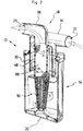
- Filter 10 may include housing 14 to which lid 18 may be attached. Such attachment may be permanent; alternatively (and preferably), lid 18 may be removable from housing 14. However, when housing 14 and lid 18 are attached, the attachment should be fluid-tight (or nearly so) to avoid creating a leakage path into or from the housing 14.
- Housing 14 may include floor 20 and may be generally cylindrical in shape, although other shapes may be utilized instead.
- Lid 18 may comprise inlet 22, outlet 26, and director 30. (Alternatively, director 30 may be part of housing 14 or otherwise not be part of lid 18.)
- Inlet 22 is defined by termination of inlet conduit 34, whereas outlet 26 is defined by termination of outlet conduit 38.
- Inlet conduit 34 is configured to impart spinning, spiral motion (downward as filter 10 is oriented in FIGS. 1-2 ) to fluid entering filter 10 via inlet 22.
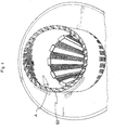
- core 42 Positioned within housing 14 may be central, inner core 42 of filter 10. As illustrated in FIGS. 1-3 , core 42 comprises first tube 46, second tube 50, disc 54, and base 58. These components may be integrally formed (as is shown in FIG. 3 ); alternatively, they may be connected in any suitable manner. Because filter 10 preferably is oriented upright when in use, first tube 46 typically will be above second tube 50. Filter 10 conceivably may be oriented otherwise than upright at times, however. Core 42 preferably is removable from within housing 14 to facilitate, among other things, removal of accumulated debris. Indeed, at least some versions of inner core 42 may include a pliable wiper or similar component attached to the periphery of base 58 so as to wipe (“squeegee") debris from the interior of the wall of housing 14 as the core 42 is removed.
- squeegee wipe
- first tube 46 is generally cylindrical, whereas second tube 50 is generally conical (or, preferably, frustoconical) in shape.
- First tube 46 additionally includes multiple perforations in the form of openings 60, allowing fluid to flow from its exterior 62 to its interior region 66.
- Interior region 66 additionally is connected to outlet conduit 38 at a nominally upper end 68 of first tube 46 so as to allow fluid within region 66 to travel via the conduit 38 to outlet 26.
- Inlet conduit 34, interior region 66, and outlet conduit 38 thus may form most or all of a primary fluid flow path through filter 10.
- Openings 60 may be formed in first tube 46 in any appropriate way.
- the openings 60 additionally may be of any number, size, or shape adequate to achieve any object of the invention.
- openings 60 comprise a significant portion of the surface area of exterior 62 so as to not provide too great a resistance to fluid flow.
- openings 60 may be angled such that spinning, debris-laden fluid must transit an acute angle A from exterior 62 to interior region 66, discouraging debris from passing through the openings 60.
- Second tube 50 is perforated. Regardless, it defines an exterior 70 whose diameter decreases from its nominally upper end 74 to its nominally lower end 78. Upper end 74 may be adjacent lower end 82 of first tube 46, whereas lower end 78 may be adjacent base 58, which in turn may be adjacent floor 20 in use.
- the maximum diameter of second tube 50 furthermore, preferably is approximately the same as, or less than, the diameter of first tube 46.
- disc 54 Positioned between or adjacent upper end 74 and lower end 82 may be disc 54.
- Disc 54 thus effectively divides filter 10 into two stages, a first stage above the disc 54 and a second stage below the disc 54 (in the orientation of FIGS. 1-3 ).
- Disc 54 preferably has--but need not necessarily have--cross-sectional shape similar to that of housing 14. If disc 54 is annular or circular, however, it should have smaller diameter than the diameter of housing 14 so that fluid may flow from the first stage to the second stage through an (annular) gap G.
- At least some versions of filter 10 may be connected, through suitable hoses or conduits, between a pump and a "suction-side" APC.
- a pump When the APC is placed within a swimming pool and the pump is activated, both filter 10 and the APC are at least partially evacuated. This action in turn causes debris-laden water to flow into and through the APC and then through a hose or conduit to inlet 22. Some of the water will travel through filter 10 in the primary flow path described above and exit via outlet 26 for continued travel toward the pump.
- filter 10 strains leaves in water rather than, for example, particles in air.
- Filter 10 does not necessarily centrifugally “spin out” particles for collection in a sheltered part of housing 14, unlike analogous structures of cyclonic air vacuum cleaners. Instead in filter 10 a high-velocity rush of water is created past a portion of a strainer (e.g. first tube 46), an aim of which is to "tear off' leaves from the water, keeping the water void of leafy debris so it may pass through openings 60 generally unrestricted.
- a strainer e.g. first tube 46
- the debris is not afforded the chance to adhere to the upper portion of the strainer (e.g. to first tube 46), as in that narrow portion the cyclone maintains a speed of water, the force of which is greater than the force of the draw through the strainer.
- the high speed water therefore "cleans" the narrow upper portion of the strainer.
- the wider, lower portion of the strainer e.g. second tube 50
- This slowing in turn encourages the light, leafy debris to attach and wrap around the lower portion of the strainer.
- the force of the draw through the strainer is greater than the force of the cyclonic water and the reverse happens--the leafy debris is collected away from the upper portion of strainer, an area desirably kept “clean.”
- An aim of filter 10, therefore, is to create a high-speed velocity stream of water past a portion of strainer and then a low-speed velocity stream of water for collection.
- This approach also may work linearly, but for convenience and compactness using a generally cylindrical housing 14 is presently preferred.
- Both first tube 42 and second tube 46 strain water thence flowing to outlet 26, resulting in more efficient straining (as opposed to more efficient cyclonic action, as desired in conventional air cyclone vacuum cleaners).
- filter 10 preferably contains no "dead zone" or low-flow sump within housing 14.
Landscapes
- Physics & Mathematics (AREA)
- Fluid Mechanics (AREA)
- Cyclones (AREA)
- Filtering Materials (AREA)
- Filtration Of Liquid (AREA)
Claims (21)
- Vorrichtung zum Filtern von Blätterschmutz, der in fließendem Wasser eines Pools oder Spas mitgerissen wird, wobei die Vorrichtung umfasst:a. einen Einlass (22);b. ein erstes Rohr (46), das (i) (A) eine Außenseite (62) und (B) einen Innenbereich (66) definiert, und (ii) Öffnungen (60) umfasst, durch die Wasser von der Außenseite zum Innenbereich fließen kann;c. einen Auslass (26), der mit dem Innenbereich (66) in Flüssigkeitsverbindung steht;d. Mittel, um Wasser, das durch den Einlass und um die Außenseite des ersten Rohrs herum fließt, eine Rotationsbewegung zu verleihen,
dadurch gekennzeichnet, dass sie weiter ein zweites Rohr (50) umfasst:- mit einem oberen Ende (74), das an ein unteres Ende (82) des ersten Rohrs (46) angrenzt,- das eine Außenseite (70) definiert, um die herum Wasser, das durch den Einlass (22), aber nicht durch die Öffnungen (60) des ersten Rohrs (46) geflossen ist, fließen kann,- das einen Innenbereich definiert,- das Öffnungen umfasst, durch die Wasser von seiner Außenseite (70) zu seinem Innenbereich fließen kann. - Vorrichtung nach Anspruch 1, wobei die Bewegung verleihenden Mittel dazu geeignet sind, Wasser mit ausreichend hoher Geschwindigkeit zu rotieren, sodass mindestens das meiste des Blätterschmutzes daran gehindert wird, an der Außenseite (62) des ersten Rohrs (46) anzuhaften, wodurch Blätterschmutz aus Wasser, das durch die Öffnungen (60) zum Innenbereich fließt, abgesiebt wird.
- Vorrichtung nach Anspruch 1 oder 2, wobei der maximale Durchmesser des zweiten Rohrs (50) derselbe wie oder kleiner als der Durchmesser des ersten Rohrs (46) ist.
- Vorrichtung nach Anspruch 3, weiter ein Gehäuse (14) umfassend, das mindestens das zweite Rohr (50) enthält, wobei das Gehäuse eine Innenseite aufweist und einen Bereich zwischen seiner Innenseite und der Außenseite des zweiten Rohrs definiert, in dem sich Blätterschmutz zur Entnahme ansammeln kann.
- Vorrichtung nach Anspruch 4, weiter einen Deckel (18) umfassend, der am Gehäuse (14) festmacht und den Einlass (22) und den Auslass (26) umfasst.
- Vorrichtung nach Anspruch 5, wobei das Gehäuse (14) eine Breite definiert, weiter eine Scheibe (54) umfassend, die (i) zwischen dem ersten (46) und zweiten (50) Rohr positioniert ist, (ii) einen Umfang definiert, und (iii) eine Größe aufweist, die kleiner ist als die Breite des Gehäuses, sodass ein Spalt (G) zwischen dem Umfang und der Innenseite des Gehäuses erzeugt wird.
- Vorrichtung nach Anspruch 6, wobei die Scheibe (54) ringförmig ist und das Gehäuse (14) allgemein zylinderförmig ist.
- Vorrichtung nach Anspruch 7, weiter einen Sockel (58) umfassend, der am zweiten Rohr festgemacht ist.
- Vorrichtung nach Anspruch 8, wobei der Sockel (58) einen Umfang definiert, weiter einen biegsamen Wischer umfassend, der am Sockel um dessen Umfang herum festgemacht ist und an der Innenseite des Gehäuses anliegt.
- Vorrichtung nach Anspruch 9, wobei das Gehäuse (14) einen Boden (20) aufweist, und der Sockel (58) zur Positionierung an den Boden angrenzend ausgebildet ist.
- Vorrichtung nach Anspruch 10, wobei das erste (46) und zweite (50) Rohr, die Scheibe (54) und der Sockel (58) als eine Einheit aus dem Gehäuse (14) entnehmbar sind.
- Vorrichtung nach Anspruch 11, wobei das erste (46) und zweite (50) Rohr, die Scheibe (54) und der Sockel (58) einstückig gebildet sind.
- Vorrichtung nach Anspruch 12, wobei das zweite Rohr (50) kegelstumpfförmig ist.
- Vorrichtung nach Anspruch 13, wobei das erste Rohr (46) allgemein zylinderförmig ist.
- Vorrichtung nach Anspruch 14, wobei das zweite Rohr (50) unter dem ersten Rohr (46) positioniert ist, wenn die Vorrichtung aufrecht steht.
- Vorrichtung nach Anspruch 15, wobei das Bewegung verleihende Mittel eine Einlassleitung (34) umfasst, die dazu ausgebildet ist, abwärtsgerichtete Spiralbewegung aufzubringen, wenn die Vorrichtung aufrecht steht.
- Vorrichtung nach Anspruch 16, weiter einen Lenker (30) umfassend, der derart ausgebildet ist, dass Wasser zwischen demselben und der Außenseite des ersten Rohrs (46) abwärts rotieren kann.
- Vorrichtung nach Anspruch 1, wobei die Öffnungen (60) des ersten Rohrs (46) derart gewinkelt sind, dass Fluid von der Außenseite (62) zum Innenbereich (66) des ersten Rohrs einen spitzen Winkel (A) durchlaufen muss.
- Verfahren zum Filtern von Blätterschmutz, der in fließendem Wasser mitgerissen wird, umfassend:a. Einleiten von schmutzbeladenem Wasser in einen Filter;b. Verleihen von Rotationsbewegung an das Wasser;c. Bringen eines ersten Teils des Wassers dazu, von der Außenseite (62) zum Immenraumbereich (66) eines ersten Rohrs (46) und von dort zu einem Auslass (26) des Filters zu dringen;d. Absieben von Blätterschmutz aus dem ersten Teil des Wassers, während dieses von der Außenseite zum Innenbereich des ersten Rohrs dringt; unde. Bringen eines zweiten Teils des Wassers dazu, außerhalb der Außenseite des ersten Rohrs durch einen Spalt (G) und um ein perforiertes zweites Rohr (50) herum, das mit einem oberen Ende (74) an ein unteres Ende (82) des ersten Rohrs (46) angrenzend positioniert ist, abwärts zu rotieren;f. Bringen des Blätterschmutzes dazu, anzuhaften und sich um das zweite Rohr (50) herumzulegen.
- Verfahren nach Anspruch 18, das das Verlangsamen der Rotation des zweiten Wasserteils um das zweite Rohr (50) herum umfasst.
- Verfahren nach Anspruch 18 oder 19, das das Verleihen von Rotationsbewegung an das Wasser mit ausreichend hoher Geschwindigkeit umfasst, sodass mindestens das meiste des Blätterschmutzes daran gehindert wird, an der Außenseite (62) des ersten Rohrs (46) anzuhaften, wodurch Blätterschmutz aus Wasser, das durch die Öffnungen (60) zum Innenbereich fließt, abgesiebt wird.
Applications Claiming Priority (3)
| Application Number | Priority Date | Filing Date | Title |
|---|---|---|---|
| US40663010P | 2010-10-26 | 2010-10-26 | |
| FR1004604A FR2967922B1 (fr) | 2010-11-26 | 2010-11-26 | Appareil et procede de filtration de debris. |
| PCT/US2011/054838 WO2012057974A1 (en) | 2010-10-26 | 2011-10-05 | Cyclonic debris filter |
Publications (2)
| Publication Number | Publication Date |
|---|---|
| EP2632602A1 EP2632602A1 (de) | 2013-09-04 |
| EP2632602B1 true EP2632602B1 (de) | 2019-03-27 |
Family
ID=44231901
Family Applications (1)
| Application Number | Title | Priority Date | Filing Date |
|---|---|---|---|
| EP11768264.1A Active EP2632602B1 (de) | 2010-10-26 | 2011-10-05 | Schmutzpartikel-zyklonabscheider |
Country Status (7)
| Country | Link |
|---|---|
| US (1) | US8888999B2 (de) |
| EP (1) | EP2632602B1 (de) |
| AU (1) | AU2011320827B2 (de) |
| CA (1) | CA2815648C (de) |
| ES (1) | ES2725851T3 (de) |
| FR (1) | FR2967922B1 (de) |
| WO (1) | WO2012057974A1 (de) |
Families Citing this family (10)
| Publication number | Priority date | Publication date | Assignee | Title |
|---|---|---|---|---|
| FR2967922B1 (fr) | 2010-11-26 | 2015-03-20 | Zodiac Pool Systems Inc | Appareil et procede de filtration de debris. |
| FR3016805A1 (fr) * | 2014-01-29 | 2015-07-31 | Piscines Desjoyaux Sa | Dispositif de filtration d'un liquide par effet cyclonique |
| ES2930241T3 (es) | 2015-01-26 | 2022-12-09 | Hayward Ind Inc | Limpiador de piscinas con separador de partículas hidrociclónico y/o sistema de accionamiento de seis rodillos |
| US9885196B2 (en) | 2015-01-26 | 2018-02-06 | Hayward Industries, Inc. | Pool cleaner power coupling |
| JP2017070875A (ja) * | 2015-10-05 | 2017-04-13 | 株式会社ニクニ | サイクロン式分離器 |
| US9885194B1 (en) | 2017-05-11 | 2018-02-06 | Hayward Industries, Inc. | Pool cleaner impeller subassembly |
| US9896858B1 (en) | 2017-05-11 | 2018-02-20 | Hayward Industries, Inc. | Hydrocyclonic pool cleaner |
| US10156083B2 (en) | 2017-05-11 | 2018-12-18 | Hayward Industries, Inc. | Pool cleaner power coupling |
| FR3077506B1 (fr) * | 2018-02-02 | 2020-01-17 | Abpool | Filtre pour dispositif de filtration |
| EP4731850A1 (de) * | 2023-06-20 | 2026-04-29 | Zodiac Pool Systems LLC | Inline-filtervorrichtung |
Family Cites Families (11)
| Publication number | Priority date | Publication date | Assignee | Title |
|---|---|---|---|---|
| BE497403A (de) | 1949-08-17 | |||
| US2918139A (en) * | 1957-05-20 | 1959-12-22 | Cottrell Res Inc | Centrifugal separator |
| US5269913A (en) * | 1991-10-02 | 1993-12-14 | Zarina Holding C.V. | Debris trap |
| US5554277A (en) * | 1995-06-05 | 1996-09-10 | Rief; Dieter J. | In-line leaf trap |
| GB9817071D0 (en) * | 1997-11-04 | 1998-10-07 | Bhr Group Ltd | Cyclone separator |
| US6200487B1 (en) * | 1997-11-05 | 2001-03-13 | Zodiac Pool Care, Inc. | In-line, in-pool water purification system |
| EP0972573A1 (de) * | 1998-07-15 | 2000-01-19 | Human net Kabushiki-Kaisya | Zyklonabscheider und Seiher dafür |
| US6488848B1 (en) * | 2000-04-24 | 2002-12-03 | Vortex International, Llc | Cleanable filter with ported cylinder adjacent screen |
| AU2002353760A1 (en) * | 2001-10-12 | 2003-04-22 | Arcelik A.S. | Vacuum cleaner |
| CN101707916B (zh) | 2007-06-20 | 2012-11-28 | 运水高有限公司 | 多路旋流沉淀过滤器 |
| FR2967922B1 (fr) | 2010-11-26 | 2015-03-20 | Zodiac Pool Systems Inc | Appareil et procede de filtration de debris. |
-
2010
- 2010-11-26 FR FR1004604A patent/FR2967922B1/fr active Active
-
2011
- 2011-10-05 WO PCT/US2011/054838 patent/WO2012057974A1/en not_active Ceased
- 2011-10-05 CA CA2815648A patent/CA2815648C/en active Active
- 2011-10-05 EP EP11768264.1A patent/EP2632602B1/de active Active
- 2011-10-05 ES ES11768264T patent/ES2725851T3/es active Active
- 2011-10-05 AU AU2011320827A patent/AU2011320827B2/en active Active
- 2011-10-05 US US13/253,117 patent/US8888999B2/en active Active
Non-Patent Citations (1)
| Title |
|---|
| None * |
Also Published As
| Publication number | Publication date |
|---|---|
| US8888999B2 (en) | 2014-11-18 |
| AU2011320827A1 (en) | 2013-05-30 |
| WO2012057974A1 (en) | 2012-05-03 |
| CA2815648C (en) | 2018-01-02 |
| AU2011320827B2 (en) | 2016-04-14 |
| US20120097589A1 (en) | 2012-04-26 |
| FR2967922A1 (fr) | 2012-06-01 |
| ES2725851T3 (es) | 2019-09-27 |
| EP2632602A1 (de) | 2013-09-04 |
| FR2967922B1 (fr) | 2015-03-20 |
| CA2815648A1 (en) | 2012-05-03 |
Similar Documents
| Publication | Publication Date | Title |
|---|---|---|
| CA2815648C (en) | Cyclonic debris filter | |
| US6491830B1 (en) | Kitchen grease removal system | |
| US6149825A (en) | Tubular vortex separator | |
| KR100630949B1 (ko) | 멀티 사이클론 집진장치 | |
| US5269913A (en) | Debris trap | |
| JP4901830B2 (ja) | 固液分離器 | |
| US11111686B2 (en) | Swimming pool cleaning apparatus having a debris separation device operating by centrifugal spinning and filtration | |
| JP2007275867A (ja) | サイクロン、サイクロン空気清浄機及びその空気清浄方法 | |
| US5866018A (en) | Vortex aquarium filter | |
| US20080272039A1 (en) | Swimming Pool Cleaning System | |
| KR20220139900A (ko) | 습식 진공 청소기 | |
| GB2367512A (en) | Multiple cyclone separation unit | |
| EP0165223A1 (de) | Zyklon mit automatischem Feststoffaustrag | |
| JP5530043B1 (ja) | バッグフィルター付きサイクロン | |
| KR100557174B1 (ko) | 진공 청소기의 미세 먼지 제거장치 | |
| CN2136066Y (zh) | 内滤式旋流高效分离器 | |
| KR20220139898A (ko) | 습식 진공 청소기를 위한 사이클론 유닛 | |
| JP3755099B2 (ja) | ろ過装置 | |
| JPH0824533A (ja) | 濾過装置 | |
| WO2000021639A1 (en) | Disposable filter bag for a pool cleaner | |
| US20190358653A1 (en) | Cyclone Filtering Device | |
| US20260009249A1 (en) | Floating debris eliminator | |
| US20020005387A1 (en) | Systems and methods for removing solids from a fluid environment | |
| JP3008489U (ja) | 流体の浄化装置 | |
| JP2002013128A (ja) | 浮遊物回収装置 |
Legal Events
| Date | Code | Title | Description |
|---|---|---|---|
| PUAI | Public reference made under article 153(3) epc to a published international application that has entered the european phase |
Free format text: ORIGINAL CODE: 0009012 |
|
| 17P | Request for examination filed |
Effective date: 20130524 |
|
| AK | Designated contracting states |
Kind code of ref document: A1 Designated state(s): AL AT BE BG CH CY CZ DE DK EE ES FI FR GB GR HR HU IE IS IT LI LT LU LV MC MK MT NL NO PL PT RO RS SE SI SK SM TR |
|
| DAX | Request for extension of the european patent (deleted) | ||
| GRAP | Despatch of communication of intention to grant a patent |
Free format text: ORIGINAL CODE: EPIDOSNIGR1 |
|
| STAA | Information on the status of an ep patent application or granted ep patent |
Free format text: STATUS: GRANT OF PATENT IS INTENDED |
|
| INTG | Intention to grant announced |
Effective date: 20180913 |
|
| GRAS | Grant fee paid |
Free format text: ORIGINAL CODE: EPIDOSNIGR3 |
|
| GRAA | (expected) grant |
Free format text: ORIGINAL CODE: 0009210 |
|
| STAA | Information on the status of an ep patent application or granted ep patent |
Free format text: STATUS: THE PATENT HAS BEEN GRANTED |
|
| RAP1 | Party data changed (applicant data changed or rights of an application transferred) |
Owner name: ZODIAC POOL SYSTEMS LLC |
|
| AK | Designated contracting states |
Kind code of ref document: B1 Designated state(s): AL AT BE BG CH CY CZ DE DK EE ES FI FR GB GR HR HU IE IS IT LI LT LU LV MC MK MT NL NO PL PT RO RS SE SI SK SM TR |
|
| REG | Reference to a national code |
Ref country code: GB Ref legal event code: FG4D |
|
| REG | Reference to a national code |
Ref country code: CH Ref legal event code: EP |
|
| REG | Reference to a national code |
Ref country code: AT Ref legal event code: REF Ref document number: 1112425 Country of ref document: AT Kind code of ref document: T Effective date: 20190415 |
|
| REG | Reference to a national code |
Ref country code: IE Ref legal event code: FG4D |
|
| REG | Reference to a national code |
Ref country code: DE Ref legal event code: R096 Ref document number: 602011057541 Country of ref document: DE |
|
| PG25 | Lapsed in a contracting state [announced via postgrant information from national office to epo] |
Ref country code: SE Free format text: LAPSE BECAUSE OF FAILURE TO SUBMIT A TRANSLATION OF THE DESCRIPTION OR TO PAY THE FEE WITHIN THE PRESCRIBED TIME-LIMIT Effective date: 20190327 Ref country code: FI Free format text: LAPSE BECAUSE OF FAILURE TO SUBMIT A TRANSLATION OF THE DESCRIPTION OR TO PAY THE FEE WITHIN THE PRESCRIBED TIME-LIMIT Effective date: 20190327 Ref country code: NO Free format text: LAPSE BECAUSE OF FAILURE TO SUBMIT A TRANSLATION OF THE DESCRIPTION OR TO PAY THE FEE WITHIN THE PRESCRIBED TIME-LIMIT Effective date: 20190627 Ref country code: LT Free format text: LAPSE BECAUSE OF FAILURE TO SUBMIT A TRANSLATION OF THE DESCRIPTION OR TO PAY THE FEE WITHIN THE PRESCRIBED TIME-LIMIT Effective date: 20190327 |
|
| REG | Reference to a national code |
Ref country code: NL Ref legal event code: MP Effective date: 20190327 |
|
| PG25 | Lapsed in a contracting state [announced via postgrant information from national office to epo] |
Ref country code: BG Free format text: LAPSE BECAUSE OF FAILURE TO SUBMIT A TRANSLATION OF THE DESCRIPTION OR TO PAY THE FEE WITHIN THE PRESCRIBED TIME-LIMIT Effective date: 20190627 Ref country code: GR Free format text: LAPSE BECAUSE OF FAILURE TO SUBMIT A TRANSLATION OF THE DESCRIPTION OR TO PAY THE FEE WITHIN THE PRESCRIBED TIME-LIMIT Effective date: 20190628 Ref country code: HR Free format text: LAPSE BECAUSE OF FAILURE TO SUBMIT A TRANSLATION OF THE DESCRIPTION OR TO PAY THE FEE WITHIN THE PRESCRIBED TIME-LIMIT Effective date: 20190327 Ref country code: NL Free format text: LAPSE BECAUSE OF FAILURE TO SUBMIT A TRANSLATION OF THE DESCRIPTION OR TO PAY THE FEE WITHIN THE PRESCRIBED TIME-LIMIT Effective date: 20190327 Ref country code: LV Free format text: LAPSE BECAUSE OF FAILURE TO SUBMIT A TRANSLATION OF THE DESCRIPTION OR TO PAY THE FEE WITHIN THE PRESCRIBED TIME-LIMIT Effective date: 20190327 Ref country code: RS Free format text: LAPSE BECAUSE OF FAILURE TO SUBMIT A TRANSLATION OF THE DESCRIPTION OR TO PAY THE FEE WITHIN THE PRESCRIBED TIME-LIMIT Effective date: 20190327 |
|
| REG | Reference to a national code |
Ref country code: AT Ref legal event code: MK05 Ref document number: 1112425 Country of ref document: AT Kind code of ref document: T Effective date: 20190327 |
|
| REG | Reference to a national code |
Ref country code: ES Ref legal event code: FG2A Ref document number: 2725851 Country of ref document: ES Kind code of ref document: T3 Effective date: 20190927 |
|
| PG25 | Lapsed in a contracting state [announced via postgrant information from national office to epo] |
Ref country code: RO Free format text: LAPSE BECAUSE OF FAILURE TO SUBMIT A TRANSLATION OF THE DESCRIPTION OR TO PAY THE FEE WITHIN THE PRESCRIBED TIME-LIMIT Effective date: 20190327 Ref country code: IT Free format text: LAPSE BECAUSE OF FAILURE TO SUBMIT A TRANSLATION OF THE DESCRIPTION OR TO PAY THE FEE WITHIN THE PRESCRIBED TIME-LIMIT Effective date: 20190327 Ref country code: SK Free format text: LAPSE BECAUSE OF FAILURE TO SUBMIT A TRANSLATION OF THE DESCRIPTION OR TO PAY THE FEE WITHIN THE PRESCRIBED TIME-LIMIT Effective date: 20190327 Ref country code: CZ Free format text: LAPSE BECAUSE OF FAILURE TO SUBMIT A TRANSLATION OF THE DESCRIPTION OR TO PAY THE FEE WITHIN THE PRESCRIBED TIME-LIMIT Effective date: 20190327 Ref country code: EE Free format text: LAPSE BECAUSE OF FAILURE TO SUBMIT A TRANSLATION OF THE DESCRIPTION OR TO PAY THE FEE WITHIN THE PRESCRIBED TIME-LIMIT Effective date: 20190327 Ref country code: AL Free format text: LAPSE BECAUSE OF FAILURE TO SUBMIT A TRANSLATION OF THE DESCRIPTION OR TO PAY THE FEE WITHIN THE PRESCRIBED TIME-LIMIT Effective date: 20190327 Ref country code: PT Free format text: LAPSE BECAUSE OF FAILURE TO SUBMIT A TRANSLATION OF THE DESCRIPTION OR TO PAY THE FEE WITHIN THE PRESCRIBED TIME-LIMIT Effective date: 20190727 |
|
| PG25 | Lapsed in a contracting state [announced via postgrant information from national office to epo] |
Ref country code: SM Free format text: LAPSE BECAUSE OF FAILURE TO SUBMIT A TRANSLATION OF THE DESCRIPTION OR TO PAY THE FEE WITHIN THE PRESCRIBED TIME-LIMIT Effective date: 20190327 Ref country code: PL Free format text: LAPSE BECAUSE OF FAILURE TO SUBMIT A TRANSLATION OF THE DESCRIPTION OR TO PAY THE FEE WITHIN THE PRESCRIBED TIME-LIMIT Effective date: 20190327 |
|
| PG25 | Lapsed in a contracting state [announced via postgrant information from national office to epo] |
Ref country code: AT Free format text: LAPSE BECAUSE OF FAILURE TO SUBMIT A TRANSLATION OF THE DESCRIPTION OR TO PAY THE FEE WITHIN THE PRESCRIBED TIME-LIMIT Effective date: 20190327 Ref country code: IS Free format text: LAPSE BECAUSE OF FAILURE TO SUBMIT A TRANSLATION OF THE DESCRIPTION OR TO PAY THE FEE WITHIN THE PRESCRIBED TIME-LIMIT Effective date: 20190727 |
|
| REG | Reference to a national code |
Ref country code: DE Ref legal event code: R097 Ref document number: 602011057541 Country of ref document: DE |
|
| PG25 | Lapsed in a contracting state [announced via postgrant information from national office to epo] |
Ref country code: DK Free format text: LAPSE BECAUSE OF FAILURE TO SUBMIT A TRANSLATION OF THE DESCRIPTION OR TO PAY THE FEE WITHIN THE PRESCRIBED TIME-LIMIT Effective date: 20190327 |
|
| PLBE | No opposition filed within time limit |
Free format text: ORIGINAL CODE: 0009261 |
|
| STAA | Information on the status of an ep patent application or granted ep patent |
Free format text: STATUS: NO OPPOSITION FILED WITHIN TIME LIMIT |
|
| PG25 | Lapsed in a contracting state [announced via postgrant information from national office to epo] |
Ref country code: SI Free format text: LAPSE BECAUSE OF FAILURE TO SUBMIT A TRANSLATION OF THE DESCRIPTION OR TO PAY THE FEE WITHIN THE PRESCRIBED TIME-LIMIT Effective date: 20190327 |
|
| 26N | No opposition filed |
Effective date: 20200103 |
|
| PG25 | Lapsed in a contracting state [announced via postgrant information from national office to epo] |
Ref country code: TR Free format text: LAPSE BECAUSE OF FAILURE TO SUBMIT A TRANSLATION OF THE DESCRIPTION OR TO PAY THE FEE WITHIN THE PRESCRIBED TIME-LIMIT Effective date: 20190327 |
|
| PG25 | Lapsed in a contracting state [announced via postgrant information from national office to epo] |
Ref country code: MC Free format text: LAPSE BECAUSE OF FAILURE TO SUBMIT A TRANSLATION OF THE DESCRIPTION OR TO PAY THE FEE WITHIN THE PRESCRIBED TIME-LIMIT Effective date: 20190327 |
|
| REG | Reference to a national code |
Ref country code: CH Ref legal event code: PL |
|
| PG25 | Lapsed in a contracting state [announced via postgrant information from national office to epo] |
Ref country code: LI Free format text: LAPSE BECAUSE OF NON-PAYMENT OF DUE FEES Effective date: 20191031 Ref country code: LU Free format text: LAPSE BECAUSE OF NON-PAYMENT OF DUE FEES Effective date: 20191005 Ref country code: CH Free format text: LAPSE BECAUSE OF NON-PAYMENT OF DUE FEES Effective date: 20191031 |
|
| REG | Reference to a national code |
Ref country code: BE Ref legal event code: MM Effective date: 20191031 |
|
| PG25 | Lapsed in a contracting state [announced via postgrant information from national office to epo] |
Ref country code: BE Free format text: LAPSE BECAUSE OF NON-PAYMENT OF DUE FEES Effective date: 20191031 |
|
| GBPC | Gb: european patent ceased through non-payment of renewal fee |
Effective date: 20191005 |
|
| PG25 | Lapsed in a contracting state [announced via postgrant information from national office to epo] |
Ref country code: IE Free format text: LAPSE BECAUSE OF NON-PAYMENT OF DUE FEES Effective date: 20191005 Ref country code: GB Free format text: LAPSE BECAUSE OF NON-PAYMENT OF DUE FEES Effective date: 20191005 |
|
| PG25 | Lapsed in a contracting state [announced via postgrant information from national office to epo] |
Ref country code: CY Free format text: LAPSE BECAUSE OF FAILURE TO SUBMIT A TRANSLATION OF THE DESCRIPTION OR TO PAY THE FEE WITHIN THE PRESCRIBED TIME-LIMIT Effective date: 20190327 |
|
| PG25 | Lapsed in a contracting state [announced via postgrant information from national office to epo] |
Ref country code: HU Free format text: LAPSE BECAUSE OF FAILURE TO SUBMIT A TRANSLATION OF THE DESCRIPTION OR TO PAY THE FEE WITHIN THE PRESCRIBED TIME-LIMIT; INVALID AB INITIO Effective date: 20111005 Ref country code: MT Free format text: LAPSE BECAUSE OF FAILURE TO SUBMIT A TRANSLATION OF THE DESCRIPTION OR TO PAY THE FEE WITHIN THE PRESCRIBED TIME-LIMIT Effective date: 20190327 |
|
| PG25 | Lapsed in a contracting state [announced via postgrant information from national office to epo] |
Ref country code: MK Free format text: LAPSE BECAUSE OF FAILURE TO SUBMIT A TRANSLATION OF THE DESCRIPTION OR TO PAY THE FEE WITHIN THE PRESCRIBED TIME-LIMIT Effective date: 20190327 |
|
| P01 | Opt-out of the competence of the unified patent court (upc) registered |
Effective date: 20230525 |
|
| PGFP | Annual fee paid to national office [announced via postgrant information from national office to epo] |
Ref country code: DE Payment date: 20251029 Year of fee payment: 15 |
|
| PGFP | Annual fee paid to national office [announced via postgrant information from national office to epo] |
Ref country code: FR Payment date: 20251027 Year of fee payment: 15 |
|
| PGFP | Annual fee paid to national office [announced via postgrant information from national office to epo] |
Ref country code: ES Payment date: 20251103 Year of fee payment: 15 |