EP2631426A1 - Compresseur à spirale - Google Patents
Compresseur à spirale Download PDFInfo
- Publication number
- EP2631426A1 EP2631426A1 EP13156716.6A EP13156716A EP2631426A1 EP 2631426 A1 EP2631426 A1 EP 2631426A1 EP 13156716 A EP13156716 A EP 13156716A EP 2631426 A1 EP2631426 A1 EP 2631426A1
- Authority
- EP
- European Patent Office
- Prior art keywords
- scroll
- fixed scroll
- circumferential surface
- discharge
- discharge cover
- Prior art date
- Legal status (The legal status is an assumption and is not a legal conclusion. Google has not performed a legal analysis and makes no representation as to the accuracy of the status listed.)
- Granted
Links
Images


Classifications
-
- F—MECHANICAL ENGINEERING; LIGHTING; HEATING; WEAPONS; BLASTING
- F04—POSITIVE - DISPLACEMENT MACHINES FOR LIQUIDS; PUMPS FOR LIQUIDS OR ELASTIC FLUIDS
- F04C—ROTARY-PISTON, OR OSCILLATING-PISTON, POSITIVE-DISPLACEMENT MACHINES FOR LIQUIDS; ROTARY-PISTON, OR OSCILLATING-PISTON, POSITIVE-DISPLACEMENT PUMPS
- F04C18/00—Rotary-piston pumps specially adapted for elastic fluids
-
- F—MECHANICAL ENGINEERING; LIGHTING; HEATING; WEAPONS; BLASTING
- F01—MACHINES OR ENGINES IN GENERAL; ENGINE PLANTS IN GENERAL; STEAM ENGINES
- F01C—ROTARY-PISTON OR OSCILLATING-PISTON MACHINES OR ENGINES
- F01C21/00—Component parts, details or accessories not provided for in groups F01C1/00 - F01C20/00
- F01C21/10—Outer members for co-operation with rotary pistons; Casings
-
- F—MECHANICAL ENGINEERING; LIGHTING; HEATING; WEAPONS; BLASTING
- F04—POSITIVE - DISPLACEMENT MACHINES FOR LIQUIDS; PUMPS FOR LIQUIDS OR ELASTIC FLUIDS
- F04C—ROTARY-PISTON, OR OSCILLATING-PISTON, POSITIVE-DISPLACEMENT MACHINES FOR LIQUIDS; ROTARY-PISTON, OR OSCILLATING-PISTON, POSITIVE-DISPLACEMENT PUMPS
- F04C18/00—Rotary-piston pumps specially adapted for elastic fluids
- F04C18/02—Rotary-piston pumps specially adapted for elastic fluids of arcuate-engagement type, i.e. with circular translatory movement of co-operating members, each member having the same number of teeth or tooth-equivalents
- F04C18/0207—Rotary-piston pumps specially adapted for elastic fluids of arcuate-engagement type, i.e. with circular translatory movement of co-operating members, each member having the same number of teeth or tooth-equivalents both members having co-operating elements in spiral form
- F04C18/0215—Rotary-piston pumps specially adapted for elastic fluids of arcuate-engagement type, i.e. with circular translatory movement of co-operating members, each member having the same number of teeth or tooth-equivalents both members having co-operating elements in spiral form where only one member is moving
-
- F—MECHANICAL ENGINEERING; LIGHTING; HEATING; WEAPONS; BLASTING
- F04—POSITIVE - DISPLACEMENT MACHINES FOR LIQUIDS; PUMPS FOR LIQUIDS OR ELASTIC FLUIDS
- F04C—ROTARY-PISTON, OR OSCILLATING-PISTON, POSITIVE-DISPLACEMENT MACHINES FOR LIQUIDS; ROTARY-PISTON, OR OSCILLATING-PISTON, POSITIVE-DISPLACEMENT PUMPS
- F04C18/00—Rotary-piston pumps specially adapted for elastic fluids
- F04C18/02—Rotary-piston pumps specially adapted for elastic fluids of arcuate-engagement type, i.e. with circular translatory movement of co-operating members, each member having the same number of teeth or tooth-equivalents
- F04C18/0207—Rotary-piston pumps specially adapted for elastic fluids of arcuate-engagement type, i.e. with circular translatory movement of co-operating members, each member having the same number of teeth or tooth-equivalents both members having co-operating elements in spiral form
- F04C18/0246—Details concerning the involute wraps or their base, e.g. geometry
- F04C18/0253—Details concerning the base
-
- F—MECHANICAL ENGINEERING; LIGHTING; HEATING; WEAPONS; BLASTING
- F04—POSITIVE - DISPLACEMENT MACHINES FOR LIQUIDS; PUMPS FOR LIQUIDS OR ELASTIC FLUIDS
- F04C—ROTARY-PISTON, OR OSCILLATING-PISTON, POSITIVE-DISPLACEMENT MACHINES FOR LIQUIDS; ROTARY-PISTON, OR OSCILLATING-PISTON, POSITIVE-DISPLACEMENT PUMPS
- F04C23/00—Combinations of two or more pumps, each being of rotary-piston or oscillating-piston type, specially adapted for elastic fluids; Pumping installations specially adapted for elastic fluids; Multi-stage pumps specially adapted for elastic fluids
- F04C23/008—Hermetic pumps
Definitions
- the present disclosure relates to a scroll compressor and, particularly, to a scroll compressor in which a discharge cover is insertedly coupled to a fixed scroll.
- a scroll compressor is a compressor for compressing a refrigerant gas by changing the volume of a compression chamber formed by a pair of opposing scrolls.
- a scroll compressor In comparison to a reciprocating compressor or a rotary compressor, a scroll compressor has high efficiency, low vibration and noise, and can be reduced in size and weight, and thus, such scroll compressors have been widely used, especially, in air-conditioners.
- a scroll compressor may be divided into a low pressure scroll compressor and a high pressure compressor according to pressure of a refrigerant filling an internal space of an airtight container thereof.
- a suction pipe communicates with an internal space of an airtight container and a refrigerant is indirectly sucked into a compression chamber through the internal space.
- a suction pipe directly communicates with a suction side of a compression unit and a refrigerant is directly sucked into the compression chamber, without passing through an internal space of an airtight container.
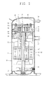
- FIG. 1 is a vertical sectional view of a related art low pressure scroll compressor.
- an internal space of an airtight container 10 is divided into a suction space S1 and a discharge space S2.
- the internal space of the airtight container 10 may be divided into the suction space S1 and the discharge space S2 by a main frame 20 or a fixed scroll 50, or may be divided into the suction space S1 and the discharge space S2 by a discharge plenum (not shown) fixed to an upper surface of the fixed scroll 50 or a discharge cover 80 as shown in FIG. 1
- the related art discharge cover 80 has an annular shape.
- An outer circumference side of the discharge cover 80 is airtightly coupled to the airtight container 10, and an inner circumference side of the discharge cover 80 is fixedly coupled to an upper surface of the fixed scroll 50 to cover a discharge opening 53.
- the outer circumferential surface of the discharge cover 80 is bent and a support protrusion 81 having a band-like shape is formed on the outer circumferential surface thereof.
- the support protrusion 81 is inserted between a shell 11 and an upper cap 12 of the airtight container 10 and supported in an axial direction.
- a gasket 90 is disposed the bottom of an inner circumference of the discharge cover 80 and supported on an upper surface of the fixed scroll 50 in order to prevent a refrigerant discharged to the discharge space S2 from being leaked to the suction space S1.
- the discharge cover 80 may be fixedly coupled to the fixed scroll 50 by using a plurality of fastening bolts B fastened to the fixed scroll 50, upon passing through the discharge cover 80 and the gasket 90.
- Reference numeral 13 denotes a lower cap
- reference numeral 30 denotes a lower frame
- reference numeral 40 denotes a driving motor
- reference numeral 41 is a stator
- reference numeral 42 denotes a rotor
- reference numeral 43 denotes a crank shaft
- reference numeral 50a denotes a fastening recess
- reference numeral 51 denotes a fixed wrap
- reference numeral 52 denotes a suction opening
- reference numeral 60 denotes an orbiting scroll
- reference numeral 61 denotes an orbiting wrap
- reference numeral 70 denotes an oldhamring
- reference numerals 80a and 90a denote fastening holes
- reference letters SP denote a suction pipe
- reference letters DP denote a discharge pipe.
- an aspect of the detailed description is to provide a scroll compressor capable of reducing the amount of components for assembling a discharge cover and an assembly time.
- Another aspect of the detailed description is to provide a scroll compressor in which a discharge cover is coupled to a fixed scroll without a bolt to reduce an area of the fixed scroll to be in contact with a discharge space having a high temperature, thus preventing a refrigerant in a compression chamber from being overheated, reducing a weight of the fixed scroll, and reducing an overall weight of the compressor.
- a scroll compressor including: an airtight container; a fixed scroll fixed to an internal space of the airtight container and having a suction opening and a discharge opening; an orbiting scroll engaged with the fixed scroll to make a rotating movement and forming a compression chamber continuously moving together with the fixed scroll, while making the rotating movement; and a discharge cover coupled to the airtight container and the fixed scroll and separating the internal space of the airtight container into a suction space communicating with the suction opening and a discharge space communicating with the discharge opening, wherein the discharge cover has an annular shape and is coupled to the fixed scroll such that an inner circumferential surface of the discharge cover overlaps with an outer circumferential surface of the fixed scroll in an axial direction.
- a scroll compressor including: an airtight container; a fixed scroll fixed to an internal space of the airtight container and having a suction opening and a discharge opening; an orbiting scroll engaged with the fixed scroll to make a rotating movement and forming a compression chamber continuously moving together with the fixed scroll, while making the rotating movement; and a discharge cover coupled to the airtight container and the fixed scroll and separating the internal space of the airtight container into a suction space communicating with the suction opening and a discharge space communicating with the discharge opening, wherein the discharge cover has an annular shape and is coupled to the fixed scroll such that a height of the lowermost point of an inner circumferential surface of the discharge cover is lower than a rear surface of the fixed scroll forming the discharge space, based on a lower end of the airtight container.
- a scroll compressor in which an internal space of an airtight container is divided into a suction space and a discharge space by a discharge cover fixed to a fixed scroll, wherein an outer circumferential surface of the discharge cover is welded to be coupled to the airtight container, an inner circumferential surface of the discharge cover is insertedly fixed to the fixed scroll, and at least a portion of the inner circumferential surface of the discharge cover is positioned at an inner side than an inner circumferential surface of the outermost wrap forming the compression chamber.
- An oil pocket portion may be formed in at least one of the inner circumferential surface of the discharge cover inserted into the outer circumferential surface of the fixed scroll and the outer circumferential surface of the fixed scroll corresponding to the inner circumferential surface of the discharge cover.
- the discharge cover may be formed such that a ratio (Di/Do) of an inner diameter Di thereof to an outer diameter Do thereof is less than 0.8.
- an internal space of an airtight container 10 may be divided into a suction space S1 as a low pressure part and a discharge space S2 as a high pressure part.
- a driving motor 40 for generating rotational force (or rotatory power) may be installed in the suction space S1 of the airtight container 10.
- a main frame 20 may be fixedly installed between the suction space S1 and the discharge space S2 of the airtight container 10.
- a subframe 30 may be installed in a lower end of the suction space S1.
- the driving motor 40 may be installed between the main frame 20 and the subframe 30, and a fixed scroll 110 may be fixedly installed on an upper surface of the main frame 20.
- An orbiting scroll 60 may be installed between the main frame 20 and the fixed scroll 110 such that it is gyrational.
- the orbiting scroll 60 may be eccentrically coupled to a crank shaft 43 of the driving motor 40 to form a pair of compression chambers P that continuously move, together with the fixed scroll 110.
- An oldhamring 70 may be installed between the fixed scroll 110 and the orbiting scroll 60 in order to prevent the orbiting scroll 60 from being rotated.
- the airtight container 10 may include a cylindrical shell 11 and an upper cap 12 and a lower cap 13 covering an upper opening end of the shell 11 and a lower opening end of the shell 11.
- a suction pipe SP may be coupled to communicate with the suction space S1 of the airtight container 10, and a discharge pipe DP may be coupled to communicate with the discharge space S2.
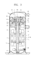
- the airtight container 10 may have the hermetically sealed discharge space S2, and the suction space as a low pressure part and the discharge space as a high pressure part may be divided by a discharge plenum (not shown) fixedly coupled to the fixed scroll 110, or as shown in FIGS. 3 and 4 , the internal space of the airtight container 10 may be divided into the suction space S1 and the discharge space S2 by a discharge cover 120 fixed to an upper surface of the fixed scroll 110 and tightly attached to an inner circumferential surface of the airtight container 10.
- an outer circumferential surface of the main frame 20 may be fixedly welded to an inner circumferential surface of the shell 11 of the airtight container 10.
- a communication hole (not shown) or a communication recess (not shown) allowing the suction space S1 and a suction opening 113 (to be described) to communicate with each other may be formed.
- a disk plate 111 of the fixed scroll 110 may have an annular shape and may be fastened to an upper surface of the main frame 20 by a bolt so as to be fixedly coupled thereto or may be press-fit and welded to be coupled to the shell 11 of the airtight container 10.
- the fixed scroll 110 includes a fixed wrap 112 protruded from the bottom of the disk plate 111 and forming the compression chamber P together with an orbiting wrap 61 of the orbiting scroll 60.
- the fixed scroll 110 includes the suction opening 113 formed on an outer circumferential surface of the disk plate 111 and allowing the suction space S1 of the airtight container 10 and the compression chamber P to communicate with each other, and a discharge opening 114 formed in a central portion of the disk plate 111 of the fixed scroll 110 and allowing the compression chamber P and the discharge space S2 of the airtight container 10 to communicate with each other.
- the fixed scroll 110 includes an annular fixed end 115 formed on an outer circumferential surface of an upper portion of the disk plate 111.
- An inner circumference sealing portion 122 of the discharge cover 120 (to be described) is press-fit to the fixed end 115 so as to be fixedly coupled thereto.
- the fixed end 115 may be formed by removing a corner portion of an upper surface of the disk plate 111 of the fixed scroll 110 by the same depth (or height) in an axial direction.
- the discharge cover 120 may be installed on an upper surface of the disk plate 111 of the fixed scroll 110 such that an internal space of the airtight container 10 is divided into the suction space S1 and the discharge space S2.
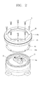
- the discharge cover 120 may be formed by pressurizing a plate body having a predetermined thickness through a pressing method, or the like, to have a ring shape when viewed in a plane (i.e., when viewed from the above).
- the outer circumference of the discharge cover 120 may be bent to form an outer circumference sealing portion 121 tightly attached to the inner circumferential surface of the airtight container 10, and a sealing protrusion 121a may be formed on an outer circumferential surface of the outer circumference sealing portion 121 and welded and coupled between the shell 11 and the upper cap 12.
- An inner circumference sealing portion 122 is formed in the inner circumference of the discharge cover 120.
- the inner circumference sealing portion 122 is inserted into the fixed end 115 of the fixed scroll 110 and tightly attached in a radial direction.
- the inner circumference sealing portion 122 covers the surrounding of the discharge opening 114 to separate the discharge opening 114 and the suction opening 113.
- the inner circumference sealing portion 122 may be insertedly coupled to the fixed end 115 such that an inner circumferential surface formed by bending an inner circumferential portion of the discharge cover 120 so as to be in contact with the fixed scroll 110 overlaps with an outer circumferential surface of the fixed scroll 110 in the axial direction.
- the lowermost point of the inner circumference sealing portion 122 of the discharge cover 120 is lower than a rear surface of the fixed scroll 110 forming the discharge space S2, so that the inner circumference sealing portion 122 of the discharge cover 120 and an outer circumferential surface of the fixed scroll 110 are coupled in an overlapping manner in the axial direction.
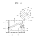
- An oil pocket portion 130 may be formed by a step surface 122a on an inner circumferential surface of the inner circumference sealing portion 122.
- the oil pocket portion 130 may fill oil between the inner circumference sealing portion 122 of the discharge cover 120 and the fixed end 115 of the fixed scroll 110 to prevent a refrigerant from being leaked by the oil.
- the oil pocket portion 130 may be formed by using the step surface 122a formed on the inner circumferential surface of the inner circumference sealing portion 122, or according to circumferences, as illustrated in FIG. 6 , the oil pocket portion 130 may be formed by using a chamfered surface 115a formed by chamfering a corner of the fixed end 115. Also, although not shown, the oil pocket portion 130 may also be formed by using a space generated by forming the inner circumference sealing portion 122 such that it is downwardly sloped.
- a horizontal directional cross-section area of the discharge cover 120 is closely related to energy efficiency (EER) of the compressor.
- EER energy efficiency
- an outer diameter Do of the discharge cover 120 is fixed to be the same, as an inner diameter Di of the discharge cover 120 is decreased (namely, as the discharge cover widens), an area of the fixed scroll 110 exposed to the discharge space S2 is decreased, and thus, a phenomenon that the fixed scroll 110 is heated by a refrigerant having a high temperature and high pressure discharged to the discharge space S2 can be reduced. Then, a specific volume of the refrigerant sucked to the compression chamber P is increased to minimize a generation of a suction loss, increasing energy efficiency of the compressor.
- the outer diameter of the discharge cover 120 is fixed to be the same, as the inner diameter thereof increases (namely, as a width of the discharge cover decreases), an area of the fixed scroll 110 exposed to the discharge space S2 is increased as much, and thus, the fixed scroll 110 is heated by the refrigerant having a high temperature and high pressure discharged to the discharge space S2 to increase a specific volume of the refrigerant sucked to the compression chamber P to increase suction loss, degrading energy efficiency of the compressor.
- the discharge cover 120 may be formed such that a ratio (Di/Do) of the inner diameter Di to the outer diameter Do is less than 0.9, preferably, less than 0.8.
- a ratio (Di/Do) of the inner diameter Di of the discharge cover 10 to the outer diameter Do thereof is more than 0.8, energy efficiency (EER) of the compressor is rapidly degraded.
- the sealing height of the inner circumference sealing portion 122 is required to be appropriately set. For example, if the height H1 of the sealing surface of the inner circumference sealing portion 122 is too low, the entire sealing area is too small to sufficiently seal the refrigerant to degrade compressor efficiency, and when the height H1 of the sealing surface is too high, the entire sealing area may be increased but an area of the fixed end 115 of the fixed scroll 110 to which the inner circumference sealing portion 122 of the discharge cover 120 is required to be tightly attached, which is required to be precisely processed, is increased to make it difficult to perform a processing operation.
- the height of the contact surface (the height of the sealing surface) between the inner circumference sealing portion 122 of the discharge cover 120 and the fixed end 115 of the fixed scroll 110 is required to range of about 5 to 25% of the height H2 of the fixed scroll 110 or to range of about 1 to 20 mm regardless of a wrap height as shown in FIG. 9 , whereby energy efficiency of the compressor can be optimized.
- a diameter D1 of an outer circumferential surface of the fixed end 115 or a diameter (i.e., the inner diameter Di) of the inner circumferential surface of the discharge cover 120 may be formed to be positioned at an inner side than the diameter D2 connecting the inner circumferential surface of the outermost wrap of the fixed scroll 110, whereby an area of the rear surface of the fixed scroll 110 exposed to the discharge space S2 can be narrowed, and thus, the fixed scroll 110 can be prevented from being overheated by the refrigerant discharged to the discharge space S2, thus reducing suction loss of the compression chamber.
- a height H3 of the oil pocket portion 130 in the axial direction may be formed to be smaller than or equal to the sealing height H 1 of the inner circumference sealing portion (i.e., the height of the surface in which the inner circumferential surface of the discharge cover and the outer circumferential surface of the fixed scroll are in contact). If the height H3 of the oil pocket portion 130 in the axial direction is greater than the sealing height H1 of the inner circumference sealing portion, as described above, the volume of the oil pocket portion 130 is reduced to reduce a sealing effect to degrade compressor performance or the width of the contact surface to be precisely processed is excessively increased to cause difficulty in processing.
- the discharge cover 120 has a sloped portion 123 formed between the outer circumference sealing portion 121 and the inner circumference sealing portion 122 and downwardly sloped toward the outer diameter, whereby pressure of the discharge space S2 acting on the discharge cover 120 can be distributed and oil can be guided to the outer circumference sealing portion 121.
- Reference numeral 41 denotes a stator and reference numeral 42 denotes a rotor.
- the scroll compressor according to the present embodiment has the following operational effects.
- the scroll compressor according to the present embodiment has the following operational effect.
- the orbiting scroll 60 eccentrically coupled to the crank shaft 43 of the driving motor 40 makes a gyrational movement to form a pair of (or two) compression chambers P continuously moving between the orbiting scroll 60 and the fixed scroll 50.
- the compression chambers P are formed continuously in several stages such that a volume thereof is gradually reduced toward the discharge opening (or a discharge chamber) 114 from the suction opening (or the suction chamber) 113.
- the refrigerant sucked from the outside of the airtight container 10 is introduced into the suction space S1, a low pressure portion, of the airtight container 10 through the suction pipe SP, and the low pressure refrigerant in the suction space S1 is introduced through the suction opening 113 of the fixed scroll 110 and move in a direction of a final compression chamber by the orbiting scroll 60 so as to be compressed, and then, discharged to the discharge space S2 of the airtight container 10 through the discharge opening 114 of the fixed scroll 110 from the final compression chamber.
- the sealing protrusion 121a of the outer circumference sealing portion 121 is interposed between the upper cap 12 and the shell 11 of the airtight container 10 and welded to be coupled, and the inner circumference sealing portion 122 is press-fit to the fixed end 115 of the fixed scroll 110 so as to be coupled.
- a predetermined amount of oil is mixedly included in the refrigerant discharged to the discharge space S2, and the oil is separated from the refrigerant and flows between the inner circumference sealing portion 122 and the fixed end 115 to fill the oil pocket portion 130.
- the fine gap can be blocked by the oil filling the oil pocket portion 130, effectively preventing the refrigerant in the discharge space S2 as a high pressure part from being leaked to the suction space S1 as a low pressure part.
- the discharge cover is coupled to the fixed scroll by a plurality of fastening bolts, the amount of components such as fastening bolts, a gasket, and the like, can be reduced, and the assembly time for assembling the components can be reduced, reducing overall production costs.
- a width corresponding to the space for bolts can be reduced in the fixed scroll, reducing the area of the fixed scroll exposed to the discharge space. Accordingly, a phenomenon in which the fixed scroll is heated by the refrigerant having a high temperature of the discharge space can be reduced, preventing the refrigerant sucked to the compression chamber from being overheated to increase suction loss, whereby compressor efficiency can be enhanced. Also, since a size of the fixed scroll is reduced to reduce a weight of the fixed scroll, a weight of the overall compressor can be reduced.
Landscapes
- Engineering & Computer Science (AREA)
- Mechanical Engineering (AREA)
- General Engineering & Computer Science (AREA)
- Applications Or Details Of Rotary Compressors (AREA)
- Rotary Pumps (AREA)
Applications Claiming Priority (1)
| Application Number | Priority Date | Filing Date | Title |
|---|---|---|---|
| KR1020120019861A KR101882713B1 (ko) | 2012-02-27 | 2012-02-27 | 스크롤 압축기 |
Publications (2)
| Publication Number | Publication Date |
|---|---|
| EP2631426A1 true EP2631426A1 (fr) | 2013-08-28 |
| EP2631426B1 EP2631426B1 (fr) | 2015-04-01 |
Family
ID=47750516
Family Applications (1)
| Application Number | Title | Priority Date | Filing Date |
|---|---|---|---|
| EP13156716.6A Not-in-force EP2631426B1 (fr) | 2012-02-27 | 2013-02-26 | Compresseur à spirale |
Country Status (5)
| Country | Link |
|---|---|
| US (1) | US9145889B2 (fr) |
| EP (1) | EP2631426B1 (fr) |
| KR (1) | KR101882713B1 (fr) |
| CN (1) | CN103291618B (fr) |
| ES (1) | ES2539266T3 (fr) |
Families Citing this family (1)
| Publication number | Priority date | Publication date | Assignee | Title |
|---|---|---|---|---|
| US9951772B2 (en) * | 2015-06-18 | 2018-04-24 | Bitzer Kuehlmaschinenbau Gmbh | Scroll compressor with unmachined separator plate and method of making same |
Citations (3)
| Publication number | Priority date | Publication date | Assignee | Title |
|---|---|---|---|---|
| JPH08312562A (ja) * | 1995-05-19 | 1996-11-26 | Mitsubishi Heavy Ind Ltd | 密閉型圧縮機 |
| US20040126261A1 (en) * | 2002-10-15 | 2004-07-01 | Bitzer Kuehlmaschinenbau Gmbh | Compressor |
| AU2010212403A1 (en) * | 2000-10-16 | 2010-09-09 | Emerson Climate Technologies, Inc | Dual volume-ratio scroll machine |
Family Cites Families (21)
| Publication number | Priority date | Publication date | Assignee | Title |
|---|---|---|---|---|
| DE69121026T2 (de) * | 1990-07-31 | 1996-12-19 | Copeland Corp | Schmiereinrichtung für Spiralmaschine |
| US5055010A (en) * | 1990-10-01 | 1991-10-08 | Copeland Corporation | Suction baffle for refrigeration compressor |
| JP3129365B2 (ja) * | 1993-08-30 | 2001-01-29 | 三菱重工業株式会社 | スクロ−ル型流体機械 |
| US5741120A (en) * | 1995-06-07 | 1998-04-21 | Copeland Corporation | Capacity modulated scroll machine |
| US5611674A (en) * | 1995-06-07 | 1997-03-18 | Copeland Corporation | Capacity modulated scroll machine |
| JPH09151866A (ja) * | 1995-11-30 | 1997-06-10 | Sanyo Electric Co Ltd | スクロール圧縮機 |
| US6056523A (en) * | 1996-02-09 | 2000-05-02 | Kyungwon-Century Co., Ltd. | Scroll-type compressor having securing blocks and multiple discharge ports |
| KR100223439B1 (ko) * | 1997-10-25 | 1999-10-15 | 윤종용 | 스크롤 압축기 |
| US6203298B1 (en) * | 1999-06-02 | 2001-03-20 | Scroll Technologies | Entrapped separator plate for scroll compressor |
| US6220839B1 (en) * | 1999-07-07 | 2001-04-24 | Copeland Corporation | Scroll compressor discharge muffler |
| KR100619723B1 (ko) * | 1999-10-02 | 2006-09-06 | 엘지전자 주식회사 | 스크롤 압축기의 고저압 분리부재 결합구조 |
| US6406266B1 (en) * | 2000-03-16 | 2002-06-18 | Scroll Technologies | Motor protector on non-orbiting scroll |
| JP2002005046A (ja) * | 2000-06-22 | 2002-01-09 | Mitsubishi Heavy Ind Ltd | スクロール圧縮機 |
| CN1201083C (zh) | 2000-06-22 | 2005-05-11 | 三菱重工业株式会社 | 涡旋型压缩机 |
| US6461130B1 (en) * | 2000-09-08 | 2002-10-08 | Scroll Technologies | Scroll compressor with unique mounting of non-orbiting scroll |
| US6418740B1 (en) * | 2001-02-22 | 2002-07-16 | Scroll Technologies | External high pressure to low pressure valve for scroll compressor |
| US6457948B1 (en) * | 2001-04-25 | 2002-10-01 | Copeland Corporation | Diagnostic system for a compressor |
| US6592344B2 (en) * | 2001-11-29 | 2003-07-15 | Scroll Technologies | Press-on insulator dish |
| US7160088B2 (en) * | 2003-09-25 | 2007-01-09 | Emerson Climate Technologies, Inc. | Scroll machine |
| US7988433B2 (en) | 2009-04-07 | 2011-08-02 | Emerson Climate Technologies, Inc. | Compressor having capacity modulation assembly |
| CN201443511U (zh) * | 2009-07-15 | 2010-04-28 | 大连三洋压缩机有限公司 | 一种涡旋式制冷压缩机 |
-
2012
- 2012-02-27 KR KR1020120019861A patent/KR101882713B1/ko active IP Right Grant
-
2013
- 2013-02-26 EP EP13156716.6A patent/EP2631426B1/fr not_active Not-in-force
- 2013-02-26 ES ES13156716.6T patent/ES2539266T3/es active Active
- 2013-02-27 CN CN201310061221.5A patent/CN103291618B/zh active Active
- 2013-02-27 US US13/778,278 patent/US9145889B2/en active Active
Patent Citations (3)
| Publication number | Priority date | Publication date | Assignee | Title |
|---|---|---|---|---|
| JPH08312562A (ja) * | 1995-05-19 | 1996-11-26 | Mitsubishi Heavy Ind Ltd | 密閉型圧縮機 |
| AU2010212403A1 (en) * | 2000-10-16 | 2010-09-09 | Emerson Climate Technologies, Inc | Dual volume-ratio scroll machine |
| US20040126261A1 (en) * | 2002-10-15 | 2004-07-01 | Bitzer Kuehlmaschinenbau Gmbh | Compressor |
Also Published As
| Publication number | Publication date |
|---|---|
| ES2539266T3 (es) | 2015-06-29 |
| CN103291618B (zh) | 2015-10-07 |
| KR20130098052A (ko) | 2013-09-04 |
| EP2631426B1 (fr) | 2015-04-01 |
| US20130224054A1 (en) | 2013-08-29 |
| CN103291618A (zh) | 2013-09-11 |
| US9145889B2 (en) | 2015-09-29 |
| KR101882713B1 (ko) | 2018-07-27 |
Similar Documents
| Publication | Publication Date | Title |
|---|---|---|
| EP2407668B1 (fr) | Compresseur à spirales | |
| US11710992B2 (en) | Motor and compressor including the same | |
| US9523361B2 (en) | Scroll compressor having back pressure chamber that operatively contains a discharge pressure and an intermediate pressure during different periods of time within a single compression cycle | |
| KR101690128B1 (ko) | 밀폐형 압축기 | |
| US20130121864A1 (en) | Scroll compressor | |
| KR20110120106A (ko) | 밀폐형 압축기 및 그 조립 장치 | |
| EP2894341B1 (fr) | Compresseur | |
| US8092199B2 (en) | Scroll compressor including a plurality of shoulder sections | |
| EP2631426B1 (fr) | Compresseur à spirale | |
| US8974204B2 (en) | Scroll compressor | |
| CN110214230B (zh) | 涡旋式压缩机 | |
| US20100172756A1 (en) | Rotary compressor | |
| JP7042455B2 (ja) | 圧縮機 | |
| CN107882738B (zh) | 压缩机 | |
| JP2008206342A (ja) | モータ回転子およびそれを用いた圧縮機 | |
| JP2017057807A (ja) | 密閉型電動圧縮機 | |
| CN219795558U (zh) | 涡旋式压缩机 | |
| KR101159331B1 (ko) | 밀폐형 회전식 압축기 | |
| KR100518025B1 (ko) | 압축기의 토출 장치 및 그 제조 방법 | |
| KR20180094708A (ko) | 압축기 | |
| KR200397834Y1 (ko) | 스크롤 압축기의 고저압 분리 장치 | |
| KR101391227B1 (ko) | 스크롤 압축기 | |
| JP2003155978A (ja) | 密閉形圧縮機及びその製造方法 | |
| KR20110114365A (ko) | 밀폐형 압축기 | |
| JP2011043072A (ja) | 密閉型圧縮機 |
Legal Events
| Date | Code | Title | Description |
|---|---|---|---|
| PUAI | Public reference made under article 153(3) epc to a published international application that has entered the european phase |
Free format text: ORIGINAL CODE: 0009012 |
|
| 17P | Request for examination filed |
Effective date: 20130320 |
|
| AK | Designated contracting states |
Kind code of ref document: A1 Designated state(s): AL AT BE BG CH CY CZ DE DK EE ES FI FR GB GR HR HU IE IS IT LI LT LU LV MC MK MT NL NO PL PT RO RS SE SI SK SM TR |
|
| AX | Request for extension of the european patent |
Extension state: BA ME |
|
| RBV | Designated contracting states (corrected) |
Designated state(s): AL AT BE BG CH CY CZ DE DK EE ES FI FR GB GR HR HU IE IS IT LI LT LU LV MC MK MT NL NO PL PT RO RS SE SI SK SM TR |
|
| GRAP | Despatch of communication of intention to grant a patent |
Free format text: ORIGINAL CODE: EPIDOSNIGR1 |
|
| INTG | Intention to grant announced |
Effective date: 20140930 |
|
| GRAS | Grant fee paid |
Free format text: ORIGINAL CODE: EPIDOSNIGR3 |
|
| GRAA | (expected) grant |
Free format text: ORIGINAL CODE: 0009210 |
|
| RAP1 | Party data changed (applicant data changed or rights of an application transferred) |
Owner name: LG ELECTRONICS INC. |
|
| AK | Designated contracting states |
Kind code of ref document: B1 Designated state(s): AL AT BE BG CH CY CZ DE DK EE ES FI FR GB GR HR HU IE IS IT LI LT LU LV MC MK MT NL NO PL PT RO RS SE SI SK SM TR |
|
| REG | Reference to a national code |
Ref country code: GB Ref legal event code: FG4D |
|
| REG | Reference to a national code |
Ref country code: CH Ref legal event code: EP |
|
| REG | Reference to a national code |
Ref country code: IE Ref legal event code: FG4D |
|
| REG | Reference to a national code |
Ref country code: DE Ref legal event code: R096 Ref document number: 602013001338 Country of ref document: DE Effective date: 20150513 |
|
| REG | Reference to a national code |
Ref country code: AT Ref legal event code: REF Ref document number: 719209 Country of ref document: AT Kind code of ref document: T Effective date: 20150515 |
|
| REG | Reference to a national code |
Ref country code: ES Ref legal event code: FG2A Ref document number: 2539266 Country of ref document: ES Kind code of ref document: T3 Effective date: 20150629 |
|
| REG | Reference to a national code |
Ref country code: NL Ref legal event code: VDEP Effective date: 20150401 |
|
| REG | Reference to a national code |
Ref country code: AT Ref legal event code: MK05 Ref document number: 719209 Country of ref document: AT Kind code of ref document: T Effective date: 20150401 |
|
| REG | Reference to a national code |
Ref country code: LT Ref legal event code: MG4D |
|
| PG25 | Lapsed in a contracting state [announced via postgrant information from national office to epo] |
Ref country code: NL Free format text: LAPSE BECAUSE OF FAILURE TO SUBMIT A TRANSLATION OF THE DESCRIPTION OR TO PAY THE FEE WITHIN THE PRESCRIBED TIME-LIMIT Effective date: 20150401 |
|
| PG25 | Lapsed in a contracting state [announced via postgrant information from national office to epo] |
Ref country code: LT Free format text: LAPSE BECAUSE OF FAILURE TO SUBMIT A TRANSLATION OF THE DESCRIPTION OR TO PAY THE FEE WITHIN THE PRESCRIBED TIME-LIMIT Effective date: 20150401 Ref country code: FI Free format text: LAPSE BECAUSE OF FAILURE TO SUBMIT A TRANSLATION OF THE DESCRIPTION OR TO PAY THE FEE WITHIN THE PRESCRIBED TIME-LIMIT Effective date: 20150401 Ref country code: CZ Free format text: LAPSE BECAUSE OF FAILURE TO SUBMIT A TRANSLATION OF THE DESCRIPTION OR TO PAY THE FEE WITHIN THE PRESCRIBED TIME-LIMIT Effective date: 20150401 Ref country code: HR Free format text: LAPSE BECAUSE OF FAILURE TO SUBMIT A TRANSLATION OF THE DESCRIPTION OR TO PAY THE FEE WITHIN THE PRESCRIBED TIME-LIMIT Effective date: 20150401 Ref country code: NO Free format text: LAPSE BECAUSE OF FAILURE TO SUBMIT A TRANSLATION OF THE DESCRIPTION OR TO PAY THE FEE WITHIN THE PRESCRIBED TIME-LIMIT Effective date: 20150701 Ref country code: PT Free format text: LAPSE BECAUSE OF FAILURE TO SUBMIT A TRANSLATION OF THE DESCRIPTION OR TO PAY THE FEE WITHIN THE PRESCRIBED TIME-LIMIT Effective date: 20150803 |
|
| PG25 | Lapsed in a contracting state [announced via postgrant information from national office to epo] |
Ref country code: AT Free format text: LAPSE BECAUSE OF FAILURE TO SUBMIT A TRANSLATION OF THE DESCRIPTION OR TO PAY THE FEE WITHIN THE PRESCRIBED TIME-LIMIT Effective date: 20150401 Ref country code: LV Free format text: LAPSE BECAUSE OF FAILURE TO SUBMIT A TRANSLATION OF THE DESCRIPTION OR TO PAY THE FEE WITHIN THE PRESCRIBED TIME-LIMIT Effective date: 20150401 Ref country code: IS Free format text: LAPSE BECAUSE OF FAILURE TO SUBMIT A TRANSLATION OF THE DESCRIPTION OR TO PAY THE FEE WITHIN THE PRESCRIBED TIME-LIMIT Effective date: 20150801 Ref country code: RS Free format text: LAPSE BECAUSE OF FAILURE TO SUBMIT A TRANSLATION OF THE DESCRIPTION OR TO PAY THE FEE WITHIN THE PRESCRIBED TIME-LIMIT Effective date: 20150401 Ref country code: GR Free format text: LAPSE BECAUSE OF FAILURE TO SUBMIT A TRANSLATION OF THE DESCRIPTION OR TO PAY THE FEE WITHIN THE PRESCRIBED TIME-LIMIT Effective date: 20150702 |
|
| REG | Reference to a national code |
Ref country code: DE Ref legal event code: R097 Ref document number: 602013001338 Country of ref document: DE |
|
| REG | Reference to a national code |
Ref country code: FR Ref legal event code: PLFP Year of fee payment: 4 |
|
| PG25 | Lapsed in a contracting state [announced via postgrant information from national office to epo] |
Ref country code: EE Free format text: LAPSE BECAUSE OF FAILURE TO SUBMIT A TRANSLATION OF THE DESCRIPTION OR TO PAY THE FEE WITHIN THE PRESCRIBED TIME-LIMIT Effective date: 20150401 Ref country code: DK Free format text: LAPSE BECAUSE OF FAILURE TO SUBMIT A TRANSLATION OF THE DESCRIPTION OR TO PAY THE FEE WITHIN THE PRESCRIBED TIME-LIMIT Effective date: 20150401 |
|
| PLBE | No opposition filed within time limit |
Free format text: ORIGINAL CODE: 0009261 |
|
| STAA | Information on the status of an ep patent application or granted ep patent |
Free format text: STATUS: NO OPPOSITION FILED WITHIN TIME LIMIT |
|
| PG25 | Lapsed in a contracting state [announced via postgrant information from national office to epo] |
Ref country code: PL Free format text: LAPSE BECAUSE OF FAILURE TO SUBMIT A TRANSLATION OF THE DESCRIPTION OR TO PAY THE FEE WITHIN THE PRESCRIBED TIME-LIMIT Effective date: 20150401 Ref country code: RO Free format text: LAPSE BECAUSE OF NON-PAYMENT OF DUE FEES Effective date: 20150401 Ref country code: SK Free format text: LAPSE BECAUSE OF FAILURE TO SUBMIT A TRANSLATION OF THE DESCRIPTION OR TO PAY THE FEE WITHIN THE PRESCRIBED TIME-LIMIT Effective date: 20150401 |
|
| 26N | No opposition filed |
Effective date: 20160105 |
|
| PG25 | Lapsed in a contracting state [announced via postgrant information from national office to epo] |
Ref country code: BE Free format text: LAPSE BECAUSE OF NON-PAYMENT OF DUE FEES Effective date: 20160229 Ref country code: SI Free format text: LAPSE BECAUSE OF FAILURE TO SUBMIT A TRANSLATION OF THE DESCRIPTION OR TO PAY THE FEE WITHIN THE PRESCRIBED TIME-LIMIT Effective date: 20150401 |
|
| PG25 | Lapsed in a contracting state [announced via postgrant information from national office to epo] |
Ref country code: BE Free format text: LAPSE BECAUSE OF FAILURE TO SUBMIT A TRANSLATION OF THE DESCRIPTION OR TO PAY THE FEE WITHIN THE PRESCRIBED TIME-LIMIT Effective date: 20150401 |
|
| REG | Reference to a national code |
Ref country code: DE Ref legal event code: R119 Ref document number: 602013001338 Country of ref document: DE |
|
| PG25 | Lapsed in a contracting state [announced via postgrant information from national office to epo] |
Ref country code: MC Free format text: LAPSE BECAUSE OF FAILURE TO SUBMIT A TRANSLATION OF THE DESCRIPTION OR TO PAY THE FEE WITHIN THE PRESCRIBED TIME-LIMIT Effective date: 20150401 Ref country code: LU Free format text: LAPSE BECAUSE OF FAILURE TO SUBMIT A TRANSLATION OF THE DESCRIPTION OR TO PAY THE FEE WITHIN THE PRESCRIBED TIME-LIMIT Effective date: 20160226 |
|
| REG | Reference to a national code |
Ref country code: CH Ref legal event code: PL |
|
| PG25 | Lapsed in a contracting state [announced via postgrant information from national office to epo] |
Ref country code: CH Free format text: LAPSE BECAUSE OF NON-PAYMENT OF DUE FEES Effective date: 20160229 Ref country code: LI Free format text: LAPSE BECAUSE OF NON-PAYMENT OF DUE FEES Effective date: 20160229 |
|
| REG | Reference to a national code |
Ref country code: IE Ref legal event code: MM4A |
|
| REG | Reference to a national code |
Ref country code: FR Ref legal event code: PLFP Year of fee payment: 5 |
|
| PG25 | Lapsed in a contracting state [announced via postgrant information from national office to epo] |
Ref country code: IE Free format text: LAPSE BECAUSE OF NON-PAYMENT OF DUE FEES Effective date: 20160226 Ref country code: DE Free format text: LAPSE BECAUSE OF NON-PAYMENT OF DUE FEES Effective date: 20160901 |
|
| PG25 | Lapsed in a contracting state [announced via postgrant information from national office to epo] |
Ref country code: SE Free format text: LAPSE BECAUSE OF FAILURE TO SUBMIT A TRANSLATION OF THE DESCRIPTION OR TO PAY THE FEE WITHIN THE PRESCRIBED TIME-LIMIT Effective date: 20150401 |
|
| PG25 | Lapsed in a contracting state [announced via postgrant information from national office to epo] |
Ref country code: MT Free format text: LAPSE BECAUSE OF FAILURE TO SUBMIT A TRANSLATION OF THE DESCRIPTION OR TO PAY THE FEE WITHIN THE PRESCRIBED TIME-LIMIT Effective date: 20150401 |
|
| GBPC | Gb: european patent ceased through non-payment of renewal fee |
Effective date: 20170226 |
|
| REG | Reference to a national code |
Ref country code: FR Ref legal event code: PLFP Year of fee payment: 6 |
|
| PG25 | Lapsed in a contracting state [announced via postgrant information from national office to epo] |
Ref country code: GB Free format text: LAPSE BECAUSE OF NON-PAYMENT OF DUE FEES Effective date: 20170226 |
|
| PGFP | Annual fee paid to national office [announced via postgrant information from national office to epo] |
Ref country code: ES Payment date: 20180315 Year of fee payment: 6 |
|
| PG25 | Lapsed in a contracting state [announced via postgrant information from national office to epo] |
Ref country code: SM Free format text: LAPSE BECAUSE OF FAILURE TO SUBMIT A TRANSLATION OF THE DESCRIPTION OR TO PAY THE FEE WITHIN THE PRESCRIBED TIME-LIMIT Effective date: 20150401 Ref country code: HU Free format text: LAPSE BECAUSE OF FAILURE TO SUBMIT A TRANSLATION OF THE DESCRIPTION OR TO PAY THE FEE WITHIN THE PRESCRIBED TIME-LIMIT; INVALID AB INITIO Effective date: 20130226 Ref country code: CY Free format text: LAPSE BECAUSE OF FAILURE TO SUBMIT A TRANSLATION OF THE DESCRIPTION OR TO PAY THE FEE WITHIN THE PRESCRIBED TIME-LIMIT Effective date: 20150401 |
|
| PGFP | Annual fee paid to national office [announced via postgrant information from national office to epo] |
Ref country code: FR Payment date: 20180111 Year of fee payment: 6 |
|
| PG25 | Lapsed in a contracting state [announced via postgrant information from national office to epo] |
Ref country code: MK Free format text: LAPSE BECAUSE OF FAILURE TO SUBMIT A TRANSLATION OF THE DESCRIPTION OR TO PAY THE FEE WITHIN THE PRESCRIBED TIME-LIMIT Effective date: 20150401 Ref country code: TR Free format text: LAPSE BECAUSE OF FAILURE TO SUBMIT A TRANSLATION OF THE DESCRIPTION OR TO PAY THE FEE WITHIN THE PRESCRIBED TIME-LIMIT Effective date: 20150401 Ref country code: MT Free format text: LAPSE BECAUSE OF FAILURE TO SUBMIT A TRANSLATION OF THE DESCRIPTION OR TO PAY THE FEE WITHIN THE PRESCRIBED TIME-LIMIT Effective date: 20160229 |
|
| PG25 | Lapsed in a contracting state [announced via postgrant information from national office to epo] |
Ref country code: BG Free format text: LAPSE BECAUSE OF FAILURE TO SUBMIT A TRANSLATION OF THE DESCRIPTION OR TO PAY THE FEE WITHIN THE PRESCRIBED TIME-LIMIT Effective date: 20150401 |
|
| PG25 | Lapsed in a contracting state [announced via postgrant information from national office to epo] |
Ref country code: AL Free format text: LAPSE BECAUSE OF FAILURE TO SUBMIT A TRANSLATION OF THE DESCRIPTION OR TO PAY THE FEE WITHIN THE PRESCRIBED TIME-LIMIT Effective date: 20150401 |
|
| PG25 | Lapsed in a contracting state [announced via postgrant information from national office to epo] |
Ref country code: FR Free format text: LAPSE BECAUSE OF NON-PAYMENT OF DUE FEES Effective date: 20190228 |
|
| REG | Reference to a national code |
Ref country code: ES Ref legal event code: FD2A Effective date: 20200330 |
|
| PG25 | Lapsed in a contracting state [announced via postgrant information from national office to epo] |
Ref country code: ES Free format text: LAPSE BECAUSE OF NON-PAYMENT OF DUE FEES Effective date: 20190227 |
|
| PGFP | Annual fee paid to national office [announced via postgrant information from national office to epo] |
Ref country code: IT Payment date: 20200212 Year of fee payment: 8 |
|
| PG25 | Lapsed in a contracting state [announced via postgrant information from national office to epo] |
Ref country code: IT Free format text: LAPSE BECAUSE OF NON-PAYMENT OF DUE FEES Effective date: 20210226 |