EP2631155B1 - Steering apparatus for a vehicle - Google Patents
Steering apparatus for a vehicle Download PDFInfo
- Publication number
- EP2631155B1 EP2631155B1 EP11834224.5A EP11834224A EP2631155B1 EP 2631155 B1 EP2631155 B1 EP 2631155B1 EP 11834224 A EP11834224 A EP 11834224A EP 2631155 B1 EP2631155 B1 EP 2631155B1
- Authority
- EP
- European Patent Office
- Prior art keywords
- lift
- vehicle
- bracket
- movable
- link member
- Prior art date
- Legal status (The legal status is an assumption and is not a legal conclusion. Google has not performed a legal analysis and makes no representation as to the accuracy of the status listed.)
- Not-in-force
Links
Images

Classifications
-
- B—PERFORMING OPERATIONS; TRANSPORTING
- B62—LAND VEHICLES FOR TRAVELLING OTHERWISE THAN ON RAILS
- B62D—MOTOR VEHICLES; TRAILERS
- B62D1/00—Steering controls, i.e. means for initiating a change of direction of the vehicle
- B62D1/02—Steering controls, i.e. means for initiating a change of direction of the vehicle vehicle-mounted
- B62D1/16—Steering columns
- B62D1/18—Steering columns yieldable or adjustable, e.g. tiltable
- B62D1/187—Steering columns yieldable or adjustable, e.g. tiltable with tilt adjustment; with tilt and axial adjustment
-
- B—PERFORMING OPERATIONS; TRANSPORTING
- B62—LAND VEHICLES FOR TRAVELLING OTHERWISE THAN ON RAILS
- B62D—MOTOR VEHICLES; TRAILERS
- B62D1/00—Steering controls, i.e. means for initiating a change of direction of the vehicle
- B62D1/02—Steering controls, i.e. means for initiating a change of direction of the vehicle vehicle-mounted
- B62D1/16—Steering columns
- B62D1/18—Steering columns yieldable or adjustable, e.g. tiltable
- B62D1/183—Steering columns yieldable or adjustable, e.g. tiltable adjustable between in-use and out-of-use positions, e.g. to improve access
-
- B—PERFORMING OPERATIONS; TRANSPORTING
- B62—LAND VEHICLES FOR TRAVELLING OTHERWISE THAN ON RAILS
- B62D—MOTOR VEHICLES; TRAILERS
- B62D1/00—Steering controls, i.e. means for initiating a change of direction of the vehicle
- B62D1/02—Steering controls, i.e. means for initiating a change of direction of the vehicle vehicle-mounted
- B62D1/16—Steering columns
- B62D1/18—Steering columns yieldable or adjustable, e.g. tiltable
- B62D1/184—Mechanisms for locking columns at selected positions
-
- B—PERFORMING OPERATIONS; TRANSPORTING
- B62—LAND VEHICLES FOR TRAVELLING OTHERWISE THAN ON RAILS
- B62D—MOTOR VEHICLES; TRAILERS
- B62D1/00—Steering controls, i.e. means for initiating a change of direction of the vehicle
- B62D1/02—Steering controls, i.e. means for initiating a change of direction of the vehicle vehicle-mounted
- B62D1/16—Steering columns
- B62D1/18—Steering columns yieldable or adjustable, e.g. tiltable
- B62D1/187—Steering columns yieldable or adjustable, e.g. tiltable with tilt adjustment; with tilt and axial adjustment
- B62D1/189—Steering columns yieldable or adjustable, e.g. tiltable with tilt adjustment; with tilt and axial adjustment the entire column being tiltable as a unit
Description
- The present invention relates to a steering apparatus for a vehicle, and more particularly to the steering apparatus provided with a tilting mechanism and a lift-up mechanism.
- According to the recent vehicles, there is known a steering apparatus provided with a tilting mechanism which is capable of adjusting a manipulating position of a steering wheel, and a lift-up mechanism which is capable of holding the steering wheel at a predetermined lift-up position. For example, in the following
Patent document 1, a tilt steering apparatus with a memory mechanism has been proposed, with respect to "a tilt steering apparatus for enabling a height of a steering wheel to be changed according to physique of a driver, driving posture and the like, wherein the apparatus is made easier in getting on and off, by lifting (tilting up) the steering wheel up to its uppermost position with a lever being manipulated, so as to prevent the steering wheel from obstructing the getting on and off" as described in its paragraph [0002], and in its paragraph [0013] disclosed is an embodiment for "acting a holding force in such a state that a tilt-lock and a memory lock are achieved, a state that only the tilt-lock is achieved, and a state that both locks are released, according to rotation of a manipulating lever, respectively". Furthermore, in the followingPatent document 2, as for a steering column apparatus "provided with a lift-up mechanism and a tilting mechanism separately" as described in its paragraph [0001], there is disclosed an apparatus provided with a motor driven lift-up mechanism. FurthermorePatent document 3 describes a steering apparatus for a vehicle which comprises a steering column for supporting a steering wheel of the vehicle, a tilting mechanism having a movable column member for pivotally supporting the steering column to be swung about a swinging center provided at a front part of a vehicle body, and a movable bracket holding the movable column member between a pair of holding portions facing each other, to adjust a manipulation position of the steering wheel, a lift-up mechanism having a fixing bracket fixed to the vehicle body, and a link member with one end thereof being supported rotatably on the movable bracket to hold the steering wheel at a predetermined lift-up position, and a manipulating lever which selectively provides a hold state for engaging the link member at an initial position or a lift-up position, and a release state for releasing the engagement of the link member. -
- Patent document 1:
- Japanese Patent Laid-open Publication No.
2001-1914
- Japanese Patent Laid-open Publication No.
- Patent document 2:
- Japanese Patent Laid-open Publication No.
2009-29325
- Japanese Patent Laid-open Publication No.
- Patent document 3:
- Publication No.:
FR 2 794 419 A1
- Publication No.:
- According to the tilt steering apparatus as disclosed in the
above Patent document 1, although the lift-up amount and tilting amount can be adjusted according to the operating amount of the manipulating lever, the lift-up amount comes to be changed depending upon the adjusted tilting position, and therefore, in the case where the maximum adjusted tilting position has been set, for example, the lift-up amount becomes small. In contrast, according to the steering column apparatus as disclosed in theabove Patent document 2, the lift-up mechanism and the tilting mechanism are provided independently, so that it can be avoided to influence each other as described above. However, since not only the tilting mechanism but also the lift-up mechanism are to be driven by motors, complicated mechanisms will be required, to result in an expensive apparatus. - Therefore, according to the present invention, in the steering apparatus provided with the tilting mechanism and lift-up mechanism, it is an object to provide an inexpensive steering apparatus which is capable of manipulating the tilting mechanism and the lift-up mechanism independently, and capable of manipulating at least the lift-up mechanism easily by a manual operation of a vehicle driver.
- To solve the above-described problems, according to the present invention, in a steering apparatus for a vehicle, which is provided with a tilting mechanism which is capable of adjusting a manipulating position of a steering wheel, and a lift-up mechanism which is capable of holding the steering wheel at a predetermined lift-up position, the tilting mechanism is provided with a movable column member for pivotally supporting the steering column to be swung about a swinging center provided at a front part of the vehicle body, and a movable bracket holding the movable column member between a pair of holding portions facing each other, and the lift-up mechanism is provided with a fixing bracket fixed to the vehicle body, and a link member with one end thereof being supported rotatably on the movable bracket, and the other one end thereof being disposed to be engaged with and removed from the fixing bracket at a rear part of the vehicle body, wherein the steering apparatus is provided with lift-up biasing means which biases the movable bracket in a direction to be lifted up from the fixing bracket, and a manipulating lever which selectively provides a hold state for engaging the link member with the fixing bracket to hold the movable bracket at an initial position or a lift-up position, and a release state for releasing the engagement of the link member with the fixing bracket.
- In the steering apparatus as described above, a supporting position of one end of the link member relative to the movable bracket and a supporting position of the other one end of the link member relative to the fixing bracket, in such a state that the movable bracket is held at the initial position, may be disposed to be placed on a single arc about the swinging center, respectively. The lift-up biasing means may be formed by a spring member installed between the fixing bracket and the movable bracket.
- Also, in the steering apparatus as described above, the fixing bracket may be provided with a plurality of grooves opened toward the rear part of the vehicle body relative to the arc, and the link member may be provided with an engaging portion to be engaged with each of the plurality of grooves.
- Furthermore, in the steering apparatus as described above, it may further comprise engaging biasing means installed between the movable bracket and the link member for biasing the link member in a direction to be engaged with the fixing bracket. The engaging biasing means may be formed by a spring member to be installed between the link member and the movable bracket.
- And, the steering apparatus as described above may further comprise lateral biasing means which prevents the movable bracket from being moved in a lateral direction, which is perpendicular to an axial direction of the steering column. The lateral biasing means may be formed by a spring member installed between the fixing bracket and the movable bracket for biasing the movable bracket in the lateral direction.
- Furthermore, the steering apparatus as described above may further comprise a telescopic mechanism which extends or shrinks the movable bracket in the axial direction of the steering column, to adjust the manipulating position of the steering wheel.
- As the present invention has been configured as described above, the following effects are achieved. That is, according to the steering apparatus of the present invention, the tilting mechanism is provided with a movable column member for pivotally supporting the steering column to be swung about a swinging center provided at a front part of a vehicle body, and a movable bracket holding the movable column member between a pair of holding portions facing each other, and the lift-up mechanism is provided with a fixing bracket fixed to the vehicle body, and a link member with one end thereof being supported rotatably on the movable bracket, and the other one end thereof being disposed to be engaged with and removed from the fixing bracket at a rear part of the vehicle body, and by means of the lift-up biasing means, the movable bracket is biased in a direction to be lifted up from the fixing bracket, and by means of the manipulating lever, the hold state for engaging the link member with the fixing bracket to hold the movable bracket at the initial position or lift-up position and the release state for releasing the engagement of the link member with the fixing bracket are configured to be capable of being selectively provided, whereby the tilting mechanism and the lift-up mechanism can be manipulated independently, and also, with the manipulating lever being operated manually by the vehicle driver, the lift-up mechanism can be manipulated easily and surely to hold the initial position or the lift-up position, or place the release state.
- Particularly, in the case where the supporting position of one end of the link member relative to the movable bracket held in its initial position and the supporting position of the other one end of the link member relative to the fixing bracket are disposed to be placed on the single arc about the swinging center, respectively, the steering apparatus having an inexpensive lift-up mechanism with high rigidity can be provided, without requiring any locking mechanism additionally.
- And, if it is provided with the fixing bracket having a plurality of grooves and the link member having the engaging portion to be engaged with each of the plurality of grooves, an easily assembled and inexpensive lift-up mechanism can be configured. Furthermore, if the engaging biasing means is installed between the movable bracket and the link member, and it is so configured to bias the link member in a direction to be engaged with the fixing bracket, the lift-up mechanism can be easily shifted into the state for holding the initial position or lift-up position.
- In addition to the above, if it is provided with the lateral biasing means as described before, the movable bracket can be prevented surely from being moved in a lateral direction, so that the lift-up manipulation can be performed in a stable state. Furthermore, if it is provided with the telescopic mechanism, the lift-up mechanism can be operated easily and surely by manual operation of the vehicle driver, even for the steering column having both of the tilting mechanism and the telescopic mechanism.
-
- [
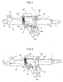
FIG.1 ] is a side view of a steering apparatus according to an embodiment of the present invention. - [
FiG.2 ] is a side view of a steering apparatus according to an embodiment of the present invention, showing its lift-up state. - [
FIG.3 ] is a side view showing a relationship between a link member and a fixing bracket in case of a lift-up manipulation, according to an embodiment of the present invention. - [
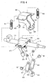
FIG.4 ] is a perspective view of a steering apparatus with parts thereof being disassembled, according to an embodiment of the present invention. - Hereinafter, will be explained a desirable embodiment of the present invention referring to drawings.
FIGS.1-4 show a steering apparatus according to an embodiment of the present invention, wherein asteering column 1 is pivotally mounted on a vehicle body (not shown) to be swung, and wherein there are disposed atilting mechanism 2 which is capable of adjusting a manipulating position of a steering wheel (not shown), and a lift-up mechanism 3 which is capable of holding the steering wheel at a predetermined lift-up position. According to the present embodiment, the steering wheel is supported at a rear end of anupper shaft 11, and anupper tube 12 is disposed coaxially so as to enclose it, so that theupper shaft 11 andupper tube 12 are configured to be movable as one body in an axial direction thereof. On the other hand, alower tube 14 is disposed coaxially so as to enclose alower shaft 13 connected to a steering mechanism (not shown), and theupper tube 12 is slidably received in thelower tube 14 in an axial direction thereof, whereby a telescopic mechanism is configured. InFIGS.1 and 2 , thelower tube 14 and theupper tube 12 are indicated together as amovable column member 10. - The above-described
tilting mechanism 2 is provided with themovable column member 10 for pivotally supporting thesteering column 1 to be swung about a swinging center (C) provided at a front part of the vehicle body, and amovable bracket 20 holding themovable column member 10 between a pair ofholding portions FIG.4 ). - Also, the lift-
up mechanism 3 is provided with afixing bracket 30 fixed to the vehicle body, and alink member 40 with one end thereof being supported rotatably on themovable bracket 20, and the other one end thereof being disposed to be engaged with and removed from thefixing bracket 30 at a rear part of the vehicle body. And, as the lift-up biasing means for biasing themovable bracket 20 in a direction to be lifted up from thefixing bracket 30, aspring member 50 comprising a pair oftension coil springs 51 and 52 (shown inFIG.4 ) is mounted. Furthermore, there is disposed a lift-up manipulatinglever 44 which is capable of selectively providing a hold state for engaging thelink member 40 with thefixing bracket 30 to be held at an initial position (P1 inFIG.1 ) or a lift-up position (P2 inFIG.2 ), and a release state for releasing the engagement of thelink member 40 with thefixing bracket 30. - The
fixing bracket 30 has a pair ofholding portions 31, 32 (shown inFIG.4 ), each of which is formed with a plurality of grooves G1, G2 opened toward the rear part of the vehicle body relative to a single arc (arc T as shown inFIG.1 ) forming a swinging locus of themovable bracket 20 about the swinging center (C). Also, thelink member 40 has a pair oflinks link 43, and which are screwed by bolts B, respectively. Tip end portions of the bolts B are rotatably supported on theholding portions movable bracket 20 via spacers S, respectively. Instead of the bolts B, pins (not shown) may be pressed into thelinks link 43 can be engaged with each of the plurality of grooves G1, G2, whereby an engaging portion of thelink member 40 to be engaged with thefixing bracket 30 is configured. On a center portion of thelink 43, fixed is the lift-up manipulatinglever 44. In response to operation of the lift-up manipulating lever 44, thelink member 40 is configured so as to be swung about a supporting position (P0 inFIG.1 ) placed at its one end, relative to themovable bracket 20. Furthermore, atension coil spring 45 is installed between themovable bracket 20 and thelink member 40, to be served as engaging biasing means, by which the link member 40 (link 43) is biased in a direction to be engaged with the fixing bracket 30 (grooves G1, G2). - Then, in such a state that the
movable bracket 20 is being held at its initial position (the state as shown inFIG.1 ), the supporting position (P0 inFIG.1 ) of one end of thelink member 40 relative to themovable bracket 20 and the supporting position (P1 inFIG.1 ) of the other one end of thelink member 40 relative to thefixing bracket 30 are disposed to be placed on the single arc (arc T as shown inFIG.1 ), which forms the swinging locus of themovable bracket 20 about the swinging center (C). Furthermore, even in such a state that themovable bracket 20 is being held at its lift-up position (the state as shown inFIG.2 ), the supporting position (P0 inFIG.1 ) of one end of thelink member 40 relative to themovable bracket 20 and the supporting position (P2 inFIG.2 ) of the other one end of thelink member 40 relative to thefixing bracket 30 may be disposed to be placed on the single arc (arc T as shown inFIG.1 ), which forms the swinging locus of themovable bracket 20 about the swinging center (C). - Furthermore, as the lateral biasing means which prevents the
movable bracket 20 from being moved in a lateral direction, which is perpendicular to an axial direction of thesteering column 1, aleaf spring 60 is installed between themovable bracket 20 and thefixing bracket 30, to bias themovable bracket 20 in the lateral direction, thereby to function as a spring member which prevents a lateral looseness against thefixing bracket 30. As the lateral biasing means, a resilient member such as rubber may be used. - According to the steering apparatus as configured above, a lift-up manipulation by means of the lift-
up mechanism 3 will be explained as follows.FIG. 3(A) shows a state prior to the lift-up manipulation, wherein thelink 43 of thelink member 40 is held at its initial position (P1 inFIG.1 ) to be engaged with the groove G1 of the fixingbracket 30. From this hold state, when the lift-up manipulatinglever 44 is drawn rearward of the vehicle body (in a direction of a white arrow), thelink 43 is released from the groove G1, as shown inFIG.3(B) , so that thelink member 40 is released from its engagement with the fixingbracket 30. Then, the link member 40 (resultantly themovable bracket 20 and the movable column member 10) is moved toward the lift-up direction (in a direction of a white arrow) by means of the biasing force of the tension coil springs 51 and 52 (FIG.4 ), thesteering column 1 is swung about the swinging center (C) to come into such a lift-up state that provides an angle α relative to a horizontal direction, as shown inFIG.2 . And, if the lift-up manipulatinglever 44 is released at this position, thelink 43 is returned by means of the biasing force of thetension coil spring 45 in a direction to be engaged with the groove G2 (in a direction of a white arrow), as shown inFIG.3(C) , so that the engaged state between the link member 40 (resultantly the movable bracket 20) and the fixingbracket 30 is held. That is, thelink 43 of thelink member 40 can be easily shifted to the lift-up position (P2 inFIG.2 ) engaged with the groove G2 of the fixingbracket 30, so that the hold state can be maintained surely. - According to the present embodiment, therefore, the
tilting mechanism 2 and the lift-upmechanism 3 can be manipulated independently. With the lift-up manipulatinglever 44 being operated by the vehicle driver, the lift-upmechanism 3 can be manipulated easily and surely, to hold the initial position (FIG.1 ) or the lift-up position (FIG.2 ), or place the release state. Also, as the supporting position (P0 inFIG.1 ) of one end of thelink member 40 relative to themovable bracket 20 and the supporting position (at least P1 inFIG.1 ) of the other one end of thelink member 40 relative to the fixingbracket 30 are disposed to be placed on the single arc (T) about the swinging center (C), respectively, as described before, the lift-upmechanism 3 can maintain its high rigidity, without requiring any locking mechanism additionally. - Furthermore, according to the present embodiment, with a
tilt manipulating lever 24 being operated, the steering wheel can be adjusted to a desired manipulating position by thetilting mechanism 2. That is, the tilting manipulation can be performed independently of the lift-up manipulation as described above. Likewise, independently of the lift-up manipulation as described above, thesteering column 1 can be moved by the telescopic mechanism as described before, in a direction to be shortened or extended, so that the steering wheel can be adjusted to its desired manipulating position. - Provided that the telescopic function is not required, the
upper tube 12 and thelower tube 14 may be formed as one body to provide the movable column member as a single member, and theupper shaft 11 and thelower shaft 13 may be formed as one body, so that a steering apparatus with the tilting function and without the telescopic function can be provided. -
- 1:
- steering column
- 2:
- tilting mechanism
- 3:
- lift-up mechanism
- C:
- swinging center
- T:
- swinging locus
- 10:
- movable column member
- 20:
- movable bracket
- 24:
- tilt manipulating lever
- 30:
- fixing bracket
- 40:
- link member
- 44:
- lift-up manipulating lever
- 50:
- spring member
- 60:
- leaf spring
Claims (10)
- A steering apparatus for a vehicle comprising:a steering column (1) for supporting a steering wheel of the vehicle;a tilting mechanism (2) having a movable column member (10) for pivotally supporting the steering column (1) to be swung about a swinging center provided at a front part of a vehicle body, and a movable bracket (20) holding the movable column member (10) between a pair of holding portions facing each other, to adjust a manipulating position of the steering wheel;a lift-up mechanism (3) having a fixing bracket (30) fixed to the vehicle body, and a link member (40) with one end thereof being supported rotatably on the movable bracket (20), and the other one end thereof being disposed to be engaged with and removed from the fixing bracket (30) at a rear part thereof, to hold the steering wheel at a predetermined lift-up position; andlift-up biasing means (50) for biasing the movable bracket in a direction to be lifted up from the fixing bracket; anda lift up manipulating lever (44) which selectively provides a hold state for engaging the link member (40) with the fixing bracket to hold the movable bracket (20) at an initial position or a lift-up position, and a release state for releasing the engagement of the link member (40) with the fixing bracket
- A steering apparatus for a vehicle as claimed in claim 1, wherein a supporting position of one end of the link member (40) relative to the movable bracket (20) and a supporting position of the other one end of the link member (40) relative to the fixing bracket (30), in such a state that the movable bracket (20) is held at the initial position, are disposed to be placed on a single arc about the swinging center, respectively.
- A steering apparatus for a vehicle as claimed in claim 1, wherein the lift-up biasing means is a spring member to be installed between the fixing bracket and the movable bracket.
- A steering apparatus for a vehicle as claimed in claim 2, wherein the lift-up biasing means is a spring member to be installed between the fixing bracket (30) and the movable bracket (20).
- A steering apparatus for a vehicle as claimed in claim 2 or 4, wherein the fixing bracket has a plurality of grooves opened toward the rear part of the vehicle body relative to the arc, and the link member (40) has an engaging portion to be engaged with each of the plurality of grooves.
- A steering apparatus for a vehicle as claimed in one of claims 1-5, further comprising engaging biasing means installed between the movable bracket (20) and the link member (40) for biasing the link member (40) in a direction to be engaged with the fixing bracket (30).
- A steering apparatus for a vehicle as claimed in claim 6, wherein the engaging biasing means is a spring member (50) installed between the link member (40) and the movable bracket (20).
- A steering apparatus for a vehicle as claimed in one of claims 1-7, further comprising lateral biasing means which prevents the movable bracket (20) from being moved in a lateral direction, which is perpendicular to an axial direction of the steering column (1).
- A steering apparatus for a vehicle as claimed in claim 8, wherein the lateral biasing means is a spring member (50) installed between the fixing bracket (30) and the movable bracket (20) for biasing the movable bracket (20) in the lateral direction.
- A steering apparatus for a vehicle as claimed in one of claims 1-9, further comprising a telescopic mechanism which extends or shrinks the movable column member (10) in the axial direction of the steering column (1), to adjust the manipulating position of the steering wheel.
Applications Claiming Priority (2)
| Application Number | Priority Date | Filing Date | Title |
|---|---|---|---|
| JP2010233471 | 2010-10-18 | ||
| PCT/JP2011/073290 WO2012053384A1 (en) | 2010-10-18 | 2011-10-11 | Vehicle steering device |
Publications (3)
| Publication Number | Publication Date |
|---|---|
| EP2631155A1 EP2631155A1 (en) | 2013-08-28 |
| EP2631155A4 EP2631155A4 (en) | 2013-11-20 |
| EP2631155B1 true EP2631155B1 (en) | 2014-11-26 |
Family
ID=45975101
Family Applications (1)
| Application Number | Title | Priority Date | Filing Date |
|---|---|---|---|
| EP11834224.5A Not-in-force EP2631155B1 (en) | 2010-10-18 | 2011-10-11 | Steering apparatus for a vehicle |
Country Status (5)
| Country | Link |
|---|---|
| US (1) | US8919815B2 (en) |
| EP (1) | EP2631155B1 (en) |
| JP (1) | JP5257641B2 (en) |
| CN (1) | CN203544098U (en) |
| WO (1) | WO2012053384A1 (en) |
Families Citing this family (17)
| Publication number | Priority date | Publication date | Assignee | Title |
|---|---|---|---|---|
| CN203358664U (en) * | 2010-10-18 | 2013-12-25 | 爱信精机株式会社 | Vehicle steering device |
| US10351159B2 (en) * | 2015-05-01 | 2019-07-16 | Steering Solutions Ip Holding Corporation | Retractable steering column with a radially projecting attachment |
| US11560169B2 (en) | 2015-06-11 | 2023-01-24 | Steering Solutions Ip Holding Corporation | Retractable steering column system and method |
| US10343706B2 (en) | 2015-06-11 | 2019-07-09 | Steering Solutions Ip Holding Corporation | Retractable steering column system, vehicle having the same, and method |
| US10577009B2 (en) | 2015-06-16 | 2020-03-03 | Steering Solutions Ip Holding Corporation | Retractable steering column assembly and method |
| DE102016111473A1 (en) | 2015-06-25 | 2016-12-29 | Steering Solutions Ip Holding Corporation | STATIONARY STEERING WHEEL ASSEMBLY AND METHOD |
| US9586610B2 (en) * | 2015-08-06 | 2017-03-07 | GM Global Technology Operations LLC | Steering column rake adjustment lock/unlock device |
| GB2550610B (en) * | 2016-05-25 | 2019-11-20 | Ford Global Tech Llc | A steering wheel assembly |
| CN107521547B (en) | 2016-06-21 | 2020-03-10 | 操纵技术Ip控股公司 | Self-locking telescopic actuator for steering column assembly |
| US10457313B2 (en) | 2016-06-28 | 2019-10-29 | Steering Solutions Ip Holding Corporation | ADAS wheel locking device |
| US10363958B2 (en) | 2016-07-26 | 2019-07-30 | Steering Solutions Ip Holding Corporation | Electric power steering mode determination and transitioning |
| US10189496B2 (en) | 2016-08-22 | 2019-01-29 | Steering Solutions Ip Holding Corporation | Steering assembly having a telescope drive lock assembly |
| US10351160B2 (en) | 2016-11-30 | 2019-07-16 | Steering Solutions Ip Holding Corporation | Steering column assembly having a sensor assembly |
| US10370022B2 (en) | 2017-02-13 | 2019-08-06 | Steering Solutions Ip Holding Corporation | Steering column assembly for autonomous vehicle |
| US10385930B2 (en) | 2017-02-21 | 2019-08-20 | Steering Solutions Ip Holding Corporation | Ball coupling assembly for steering column assembly |
| DE112019001599T5 (en) * | 2018-03-27 | 2020-12-24 | Nsk Ltd. | Steering device |
| US10974756B2 (en) | 2018-07-31 | 2021-04-13 | Steering Solutions Ip Holding Corporation | Clutch device latching system and method |
Family Cites Families (9)
| Publication number | Priority date | Publication date | Assignee | Title |
|---|---|---|---|---|
| JPH085898Y2 (en) * | 1989-04-28 | 1996-02-21 | 日本精工株式会社 | Tilt-type steering device with flip-up mechanism |
| US6036228A (en) * | 1998-05-04 | 2000-03-14 | General Motors Corporation | Adjustable steering column for motor vehicle |
| FR2794419B1 (en) | 1999-06-03 | 2001-08-24 | Peugeot Citroen Automobiles Sa | STEERING COLUMN ASSEMBLY |
| JP3673429B2 (en) | 1999-06-21 | 2005-07-20 | 光洋精工株式会社 | Tilt steering device with memory mechanism |
| KR100510416B1 (en) * | 2003-09-06 | 2005-08-26 | 현대모비스 주식회사 | Energy absorbing tilting steering column for a vehicle |
| JP2005132288A (en) * | 2003-10-31 | 2005-05-26 | Nsk Ltd | Steering column device for vehicle and car body equipment for vehicle |
| JP2006137386A (en) * | 2004-11-15 | 2006-06-01 | Aisin Seiki Co Ltd | Steering flip-up device |
| JP2009029325A (en) | 2007-07-30 | 2009-02-12 | Fuji Kiko Co Ltd | Steering column device |
| US7798037B2 (en) * | 2008-02-08 | 2010-09-21 | Gm Global Technology Operations, Inc. | Wedge arm positive rake lock |
-
2011
- 2011-10-11 CN CN201190000806.0U patent/CN203544098U/en not_active Expired - Fee Related
- 2011-10-11 JP JP2012539677A patent/JP5257641B2/en not_active Expired - Fee Related
- 2011-10-11 US US13/808,224 patent/US8919815B2/en not_active Expired - Fee Related
- 2011-10-11 EP EP11834224.5A patent/EP2631155B1/en not_active Not-in-force
- 2011-10-11 WO PCT/JP2011/073290 patent/WO2012053384A1/en active Application Filing
Also Published As
| Publication number | Publication date |
|---|---|
| CN203544098U (en) | 2014-04-16 |
| US20130104689A1 (en) | 2013-05-02 |
| EP2631155A4 (en) | 2013-11-20 |
| EP2631155A1 (en) | 2013-08-28 |
| WO2012053384A1 (en) | 2012-04-26 |
| US8919815B2 (en) | 2014-12-30 |
| JP5257641B2 (en) | 2013-08-07 |
| JPWO2012053384A1 (en) | 2014-02-24 |
Similar Documents
| Publication | Publication Date | Title |
|---|---|---|
| EP2631155B1 (en) | Steering apparatus for a vehicle | |
| JP4567040B2 (en) | Tilt telescopic steering device | |
| US11084519B2 (en) | Steering device | |
| JP2009061926A (en) | Steering column device | |
| US20190047606A1 (en) | Steering Column Assembly | |
| EP2631156B1 (en) | Steering apparatus for a vehicle | |
| JP4985443B2 (en) | Steering column device | |
| JP4835017B2 (en) | Steering device | |
| EP3067248B1 (en) | Steering apparatus | |
| EP3845434A1 (en) | Traveling vehicle | |
| JP2009143299A (en) | Vehicular steering device | |
| JP4694546B2 (en) | Tilt telescopic steering device | |
| KR101615221B1 (en) | Latching apparatus for steering device for vehicle | |
| KR100343578B1 (en) | Steering system for automobile | |
| JP2015137052A (en) | Steering column device | |
| WO2012060210A1 (en) | Tilt steering device for vehicle | |
| KR100655712B1 (en) | A structure for steering column bracket ring cage | |
| JP2011183968A (en) | Steering device for vehicle | |
| KR100462680B1 (en) | Control unit for tilting a cab of a truck | |
| KR102464179B1 (en) | steering column | |
| JP2012166711A (en) | Steering column for vehicle | |
| EP2607205B1 (en) | A steering column arrangement | |
| JP2001158365A (en) | Steering device for vehicle | |
| JP4715225B2 (en) | Steering device support structure | |
| KR20120134363A (en) | Steering column for vehicle |
Legal Events
| Date | Code | Title | Description |
|---|---|---|---|
| PUAI | Public reference made under article 153(3) epc to a published international application that has entered the european phase |
Free format text: ORIGINAL CODE: 0009012 |
|
| 17P | Request for examination filed |
Effective date: 20130416 |
|
| AK | Designated contracting states |
Kind code of ref document: A1 Designated state(s): AL AT BE BG CH CY CZ DE DK EE ES FI FR GB GR HR HU IE IS IT LI LT LU LV MC MK MT NL NO PL PT RO RS SE SI SK SM TR |
|
| A4 | Supplementary search report drawn up and despatched |
Effective date: 20131018 |
|
| RIC1 | Information provided on ipc code assigned before grant |
Ipc: B62D 1/183 20060101AFI20131014BHEP |
|
| DAX | Request for extension of the european patent (deleted) | ||
| REG | Reference to a national code |
Ref country code: DE Ref legal event code: R079 Ref document number: 602011011813 Country of ref document: DE Free format text: PREVIOUS MAIN CLASS: B62D0001180000 Ipc: B62D0001183000 |
|
| GRAP | Despatch of communication of intention to grant a patent |
Free format text: ORIGINAL CODE: EPIDOSNIGR1 |
|
| RIC1 | Information provided on ipc code assigned before grant |
Ipc: B62D 1/183 20060101AFI20140314BHEP |
|
| INTG | Intention to grant announced |
Effective date: 20140415 |
|
| GRAS | Grant fee paid |
Free format text: ORIGINAL CODE: EPIDOSNIGR3 |
|
| RIN1 | Information on inventor provided before grant (corrected) |
Inventor name: OSHITA MORITO Inventor name: INAYOSHI HIDETOSHI Inventor name: MARUTANI TAKESHI |
|
| RAP1 | Party data changed (applicant data changed or rights of an application transferred) |
Owner name: AISIN SEIKI KABUSHIKI KAISHA |
|
| RIN1 | Information on inventor provided before grant (corrected) |
Inventor name: INAYOSHI HIDETOSHI Inventor name: OSHITA MORITO Inventor name: MARUTANI TAKESHI |
|
| RIN1 | Information on inventor provided before grant (corrected) |
Inventor name: INAYOSHI HIDETOSHI Inventor name: OSHITA MORITO Inventor name: MARUTANI TAKESHI |
|
| GRAA | (expected) grant |
Free format text: ORIGINAL CODE: 0009210 |
|
| AK | Designated contracting states |
Kind code of ref document: B1 Designated state(s): AL AT BE BG CH CY CZ DE DK EE ES FI FR GB GR HR HU IE IS IT LI LT LU LV MC MK MT NL NO PL PT RO RS SE SI SK SM TR |
|
| REG | Reference to a national code |
Ref country code: GB Ref legal event code: FG4D |
|
| REG | Reference to a national code |
Ref country code: CH Ref legal event code: EP |
|
| REG | Reference to a national code |
Ref country code: AT Ref legal event code: REF Ref document number: 697986 Country of ref document: AT Kind code of ref document: T Effective date: 20141215 |
|
| REG | Reference to a national code |
Ref country code: IE Ref legal event code: FG4D |
|
| REG | Reference to a national code |
Ref country code: DE Ref legal event code: R096 Ref document number: 602011011813 Country of ref document: DE Effective date: 20150108 |
|
| REG | Reference to a national code |
Ref country code: NL Ref legal event code: VDEP Effective date: 20141126 |
|
| REG | Reference to a national code |
Ref country code: AT Ref legal event code: MK05 Ref document number: 697986 Country of ref document: AT Kind code of ref document: T Effective date: 20141126 |
|
| REG | Reference to a national code |
Ref country code: LT Ref legal event code: MG4D |
|
| PG25 | Lapsed in a contracting state [announced via postgrant information from national office to epo] |
Ref country code: PT Free format text: LAPSE BECAUSE OF FAILURE TO SUBMIT A TRANSLATION OF THE DESCRIPTION OR TO PAY THE FEE WITHIN THE PRESCRIBED TIME-LIMIT Effective date: 20150326 Ref country code: NO Free format text: LAPSE BECAUSE OF FAILURE TO SUBMIT A TRANSLATION OF THE DESCRIPTION OR TO PAY THE FEE WITHIN THE PRESCRIBED TIME-LIMIT Effective date: 20150226 Ref country code: ES Free format text: LAPSE BECAUSE OF FAILURE TO SUBMIT A TRANSLATION OF THE DESCRIPTION OR TO PAY THE FEE WITHIN THE PRESCRIBED TIME-LIMIT Effective date: 20141126 Ref country code: IS Free format text: LAPSE BECAUSE OF FAILURE TO SUBMIT A TRANSLATION OF THE DESCRIPTION OR TO PAY THE FEE WITHIN THE PRESCRIBED TIME-LIMIT Effective date: 20150326 Ref country code: LT Free format text: LAPSE BECAUSE OF FAILURE TO SUBMIT A TRANSLATION OF THE DESCRIPTION OR TO PAY THE FEE WITHIN THE PRESCRIBED TIME-LIMIT Effective date: 20141126 Ref country code: NL Free format text: LAPSE BECAUSE OF FAILURE TO SUBMIT A TRANSLATION OF THE DESCRIPTION OR TO PAY THE FEE WITHIN THE PRESCRIBED TIME-LIMIT Effective date: 20141126 Ref country code: FI Free format text: LAPSE BECAUSE OF FAILURE TO SUBMIT A TRANSLATION OF THE DESCRIPTION OR TO PAY THE FEE WITHIN THE PRESCRIBED TIME-LIMIT Effective date: 20141126 |
|
| PG25 | Lapsed in a contracting state [announced via postgrant information from national office to epo] |
Ref country code: LV Free format text: LAPSE BECAUSE OF FAILURE TO SUBMIT A TRANSLATION OF THE DESCRIPTION OR TO PAY THE FEE WITHIN THE PRESCRIBED TIME-LIMIT Effective date: 20141126 Ref country code: RS Free format text: LAPSE BECAUSE OF FAILURE TO SUBMIT A TRANSLATION OF THE DESCRIPTION OR TO PAY THE FEE WITHIN THE PRESCRIBED TIME-LIMIT Effective date: 20141126 Ref country code: AT Free format text: LAPSE BECAUSE OF FAILURE TO SUBMIT A TRANSLATION OF THE DESCRIPTION OR TO PAY THE FEE WITHIN THE PRESCRIBED TIME-LIMIT Effective date: 20141126 Ref country code: GR Free format text: LAPSE BECAUSE OF FAILURE TO SUBMIT A TRANSLATION OF THE DESCRIPTION OR TO PAY THE FEE WITHIN THE PRESCRIBED TIME-LIMIT Effective date: 20150227 Ref country code: SE Free format text: LAPSE BECAUSE OF FAILURE TO SUBMIT A TRANSLATION OF THE DESCRIPTION OR TO PAY THE FEE WITHIN THE PRESCRIBED TIME-LIMIT Effective date: 20141126 Ref country code: CY Free format text: LAPSE BECAUSE OF FAILURE TO SUBMIT A TRANSLATION OF THE DESCRIPTION OR TO PAY THE FEE WITHIN THE PRESCRIBED TIME-LIMIT Effective date: 20141126 Ref country code: HR Free format text: LAPSE BECAUSE OF FAILURE TO SUBMIT A TRANSLATION OF THE DESCRIPTION OR TO PAY THE FEE WITHIN THE PRESCRIBED TIME-LIMIT Effective date: 20141126 |
|
| PG25 | Lapsed in a contracting state [announced via postgrant information from national office to epo] |
Ref country code: CZ Free format text: LAPSE BECAUSE OF FAILURE TO SUBMIT A TRANSLATION OF THE DESCRIPTION OR TO PAY THE FEE WITHIN THE PRESCRIBED TIME-LIMIT Effective date: 20141126 Ref country code: SK Free format text: LAPSE BECAUSE OF FAILURE TO SUBMIT A TRANSLATION OF THE DESCRIPTION OR TO PAY THE FEE WITHIN THE PRESCRIBED TIME-LIMIT Effective date: 20141126 Ref country code: RO Free format text: LAPSE BECAUSE OF FAILURE TO SUBMIT A TRANSLATION OF THE DESCRIPTION OR TO PAY THE FEE WITHIN THE PRESCRIBED TIME-LIMIT Effective date: 20141126 Ref country code: EE Free format text: LAPSE BECAUSE OF FAILURE TO SUBMIT A TRANSLATION OF THE DESCRIPTION OR TO PAY THE FEE WITHIN THE PRESCRIBED TIME-LIMIT Effective date: 20141126 Ref country code: DK Free format text: LAPSE BECAUSE OF FAILURE TO SUBMIT A TRANSLATION OF THE DESCRIPTION OR TO PAY THE FEE WITHIN THE PRESCRIBED TIME-LIMIT Effective date: 20141126 |
|
| REG | Reference to a national code |
Ref country code: DE Ref legal event code: R097 Ref document number: 602011011813 Country of ref document: DE |
|
| PG25 | Lapsed in a contracting state [announced via postgrant information from national office to epo] |
Ref country code: PL Free format text: LAPSE BECAUSE OF FAILURE TO SUBMIT A TRANSLATION OF THE DESCRIPTION OR TO PAY THE FEE WITHIN THE PRESCRIBED TIME-LIMIT Effective date: 20141126 |
|
| PLBE | No opposition filed within time limit |
Free format text: ORIGINAL CODE: 0009261 |
|
| STAA | Information on the status of an ep patent application or granted ep patent |
Free format text: STATUS: NO OPPOSITION FILED WITHIN TIME LIMIT |
|
| 26N | No opposition filed |
Effective date: 20150827 |
|
| PG25 | Lapsed in a contracting state [announced via postgrant information from national office to epo] |
Ref country code: IT Free format text: LAPSE BECAUSE OF FAILURE TO SUBMIT A TRANSLATION OF THE DESCRIPTION OR TO PAY THE FEE WITHIN THE PRESCRIBED TIME-LIMIT Effective date: 20141126 |
|
| PG25 | Lapsed in a contracting state [announced via postgrant information from national office to epo] |
Ref country code: SI Free format text: LAPSE BECAUSE OF FAILURE TO SUBMIT A TRANSLATION OF THE DESCRIPTION OR TO PAY THE FEE WITHIN THE PRESCRIBED TIME-LIMIT Effective date: 20141126 |
|
| PG25 | Lapsed in a contracting state [announced via postgrant information from national office to epo] |
Ref country code: LU Free format text: LAPSE BECAUSE OF FAILURE TO SUBMIT A TRANSLATION OF THE DESCRIPTION OR TO PAY THE FEE WITHIN THE PRESCRIBED TIME-LIMIT Effective date: 20151011 |
|
| REG | Reference to a national code |
Ref country code: CH Ref legal event code: PL |
|
| GBPC | Gb: european patent ceased through non-payment of renewal fee |
Effective date: 20151011 |
|
| PG25 | Lapsed in a contracting state [announced via postgrant information from national office to epo] |
Ref country code: MC Free format text: LAPSE BECAUSE OF FAILURE TO SUBMIT A TRANSLATION OF THE DESCRIPTION OR TO PAY THE FEE WITHIN THE PRESCRIBED TIME-LIMIT Effective date: 20141126 |
|
| REG | Reference to a national code |
Ref country code: IE Ref legal event code: MM4A |
|
| PG25 | Lapsed in a contracting state [announced via postgrant information from national office to epo] |
Ref country code: GB Free format text: LAPSE BECAUSE OF NON-PAYMENT OF DUE FEES Effective date: 20151011 Ref country code: LI Free format text: LAPSE BECAUSE OF NON-PAYMENT OF DUE FEES Effective date: 20151031 Ref country code: CH Free format text: LAPSE BECAUSE OF NON-PAYMENT OF DUE FEES Effective date: 20151031 |
|
| REG | Reference to a national code |
Ref country code: FR Ref legal event code: PLFP Year of fee payment: 6 |
|
| PG25 | Lapsed in a contracting state [announced via postgrant information from national office to epo] |
Ref country code: IE Free format text: LAPSE BECAUSE OF NON-PAYMENT OF DUE FEES Effective date: 20151011 |
|
| PG25 | Lapsed in a contracting state [announced via postgrant information from national office to epo] |
Ref country code: SM Free format text: LAPSE BECAUSE OF FAILURE TO SUBMIT A TRANSLATION OF THE DESCRIPTION OR TO PAY THE FEE WITHIN THE PRESCRIBED TIME-LIMIT Effective date: 20141126 Ref country code: HU Free format text: LAPSE BECAUSE OF FAILURE TO SUBMIT A TRANSLATION OF THE DESCRIPTION OR TO PAY THE FEE WITHIN THE PRESCRIBED TIME-LIMIT; INVALID AB INITIO Effective date: 20111011 Ref country code: BG Free format text: LAPSE BECAUSE OF FAILURE TO SUBMIT A TRANSLATION OF THE DESCRIPTION OR TO PAY THE FEE WITHIN THE PRESCRIBED TIME-LIMIT Effective date: 20141126 |
|
| PG25 | Lapsed in a contracting state [announced via postgrant information from national office to epo] |
Ref country code: MT Free format text: LAPSE BECAUSE OF FAILURE TO SUBMIT A TRANSLATION OF THE DESCRIPTION OR TO PAY THE FEE WITHIN THE PRESCRIBED TIME-LIMIT Effective date: 20141126 |
|
| REG | Reference to a national code |
Ref country code: FR Ref legal event code: PLFP Year of fee payment: 7 |
|
| PG25 | Lapsed in a contracting state [announced via postgrant information from national office to epo] |
Ref country code: BE Free format text: LAPSE BECAUSE OF FAILURE TO SUBMIT A TRANSLATION OF THE DESCRIPTION OR TO PAY THE FEE WITHIN THE PRESCRIBED TIME-LIMIT Effective date: 20141126 |
|
| PG25 | Lapsed in a contracting state [announced via postgrant information from national office to epo] |
Ref country code: MK Free format text: LAPSE BECAUSE OF FAILURE TO SUBMIT A TRANSLATION OF THE DESCRIPTION OR TO PAY THE FEE WITHIN THE PRESCRIBED TIME-LIMIT Effective date: 20141126 Ref country code: TR Free format text: LAPSE BECAUSE OF FAILURE TO SUBMIT A TRANSLATION OF THE DESCRIPTION OR TO PAY THE FEE WITHIN THE PRESCRIBED TIME-LIMIT Effective date: 20141126 |
|
| REG | Reference to a national code |
Ref country code: FR Ref legal event code: PLFP Year of fee payment: 8 |
|
| PG25 | Lapsed in a contracting state [announced via postgrant information from national office to epo] |
Ref country code: AL Free format text: LAPSE BECAUSE OF FAILURE TO SUBMIT A TRANSLATION OF THE DESCRIPTION OR TO PAY THE FEE WITHIN THE PRESCRIBED TIME-LIMIT Effective date: 20141126 |
|
| PGFP | Annual fee paid to national office [announced via postgrant information from national office to epo] |
Ref country code: FR Payment date: 20190913 Year of fee payment: 9 |
|
| PGFP | Annual fee paid to national office [announced via postgrant information from national office to epo] |
Ref country code: DE Payment date: 20191001 Year of fee payment: 9 |
|
| REG | Reference to a national code |
Ref country code: DE Ref legal event code: R119 Ref document number: 602011011813 Country of ref document: DE |
|
| PG25 | Lapsed in a contracting state [announced via postgrant information from national office to epo] |
Ref country code: DE Free format text: LAPSE BECAUSE OF NON-PAYMENT OF DUE FEES Effective date: 20210501 Ref country code: FR Free format text: LAPSE BECAUSE OF NON-PAYMENT OF DUE FEES Effective date: 20201031 |