JP3673429B2 - Tilt steering device with memory mechanism - Google Patents
Tilt steering device with memory mechanism Download PDFInfo
- Publication number
- JP3673429B2 JP3673429B2 JP17427999A JP17427999A JP3673429B2 JP 3673429 B2 JP3673429 B2 JP 3673429B2 JP 17427999 A JP17427999 A JP 17427999A JP 17427999 A JP17427999 A JP 17427999A JP 3673429 B2 JP3673429 B2 JP 3673429B2
- Authority
- JP
- Japan
- Prior art keywords
- tilt
- bracket
- memory
- fixed
- side plate
- Prior art date
- Legal status (The legal status is an assumption and is not a legal conclusion. Google has not performed a legal analysis and makes no representation as to the accuracy of the status listed.)
- Expired - Fee Related
Links
- 238000003825 pressing Methods 0.000 claims description 3
- 230000004323 axial length Effects 0.000 description 3
- 238000006073 displacement reaction Methods 0.000 description 3
- 230000003247 decreasing effect Effects 0.000 description 2
- 238000010586 diagram Methods 0.000 description 2
- 238000005096 rolling process Methods 0.000 description 2
- 238000005452 bending Methods 0.000 description 1
- 230000007423 decrease Effects 0.000 description 1
- 230000000694 effects Effects 0.000 description 1
- 230000005489 elastic deformation Effects 0.000 description 1
- 230000009191 jumping Effects 0.000 description 1
- 238000000034 method Methods 0.000 description 1
- 238000012986 modification Methods 0.000 description 1
- 230000004048 modification Effects 0.000 description 1
- 238000003466 welding Methods 0.000 description 1
Images


Landscapes
- Steering Controls (AREA)
Description
【0001】
【発明の属する技術分野】
本発明は、所望の高さにチルト調節されたステアリングホイールの位置を記憶しておき、チルトアップ状態のステアリングホイールを下降させたときに、自動的に上記所望の高さの位置に復帰させることができるメモリ機構付きチルトステアリング装置に関する。
【0002】
【従来の技術】
運転者の体格や運転姿勢等に応じてステアリングホイールの高さを変えられるようにしたチルトステアリング装置において、ステアリングホイールが乗降の妨げとならないように、レバーの操作によりステアリングホイールを最上位置まで跳ね上げて(チルトアップして)、乗降を容易にするための装置が提供されている。
【0003】
この種の装置において、チルトアップ前にチルト調節されたステアリングホイールの高さ位置を記憶しておくメモリを設けたものがある。すなわち、ばねの弾力でステアリングホイールをチルトアップした状態で乗降した後、ステアリングホイールを下降させると、メモリされた高さ位置に自動的に復帰させることができるわけである。
【0004】
例えば、ステアリングコラムをアッパチューブとロアチューブで構成し、アッパチューブの下端に固定されたチルトブラケットを、ロアチューブの上端に固定された固定ブラケットに設けられたチルト中心軸の回りに揺動可能に連結するようにした、いわゆる中折れ式のチルトステアリング装置がある。この種の中折れ式のものでは、チルトブラケットに組み付けられたポールを固定ブラケットに設けたラチェットに係合させてチルトロックを達成する。また、メモリ機構としては、チルトブラケットに組み付けられたチルトカムを、ラチェットに固着されたメモリピンにチルトブラケットの下方への揺動時に係合させるようにするものがある(例えば特開平5−116634号公報参照)。
【0005】
【発明が解決しようとする課題】
上記公報の装置では、チルトロック及びその解除は、チルト中心軸の回りに回動自在なチルトレバーの操作により行われ、メモリ機構のメモリ位置の変更は、チルトレバーとは別個に設けられた位置決め機構によりチルトカムの回動位置を変更操作することにより行われる。このようにチルト調整とメモリ調整を別々の操作部材で行うので、構造が複雑となり、またコンパクト化の妨げともなる。
【0006】
一方、簡易チルト式とも呼ばれるいわゆる足元オンチルト方式のチルトステアリング装置では、メモリ機構を設けることが非常に困難であり、実際上、そのような装置は実現化されていない。
ところが、この種の簡易チルト式のチルトステアリング装置においても、メモリ機構の装着が要望されている。
【0007】
本発明は上記課題に鑑みてなされたものであり、いわゆる簡易チルト式において、構造が簡単で操作が容易なメモリ機構付きチルトステアリング装置を提供することである。
【0008】
【課題を解決するための手段】
上記目的を達成するための課題解決手段として、請求項1記載の発明の態様は、チルト中心の回りに下端部が揺動可能に支持され、ステアリングシャフトを回動可能に支承するステアリングコラムと、このステアリングコラムに固定されたチルトブラケットと、チルトブラケットの固定ブラケットに対する固定の解除によりチルトアップばねによってステアリングホイールを上死点までチルトアップ可能なチルトステアリング装置において、固定ブラケット及びチルトブラケットの一方に設けられた横長孔と他方に設けられた円弧状の縦長孔を回動可能に挿通した状態で、固定ブラケットに対するチルトブラケットの揺動を許容する操作軸と、この操作軸の回りに回転し且つ手動操作される操作レバーと、上記固定ブラケットに操作軸と平行な支軸の回りに揺動自在に支持され、付勢ばねによって付勢されてチルトブラケットの揺動に追従可能であって、ステアリングコラムを受ける位置に固定されるチルトメモリと、固定ブラケットに設けられた側板であって、上端を固定端とし下端を自由端として弾性変形可能な片持ち状の側板と、固定ブラケットの上記片持ち状の側板の側面の、固定端と自由端との間の部分に設けられ、チルトブラケットの側板の側面に対向する第1の領域と、固定ブラケットの上記片持ち状の側板の側面の、第1の領域よりも自由端側の部分に設けられ、チルトメモリの側板の側面に対向する第2の領域と、操作レバーの回動に伴って上記固定ブラケットの側板を弾性変形させて、上記第1及び第2の領域を対応するチルトブラケットの側板の側面及びチルトメモリの側板の側面に押圧する駆動部材とを備え、上記第1の領域がチルトブラケットの側板の側面に摩擦係合してチルトロックを達成するまでの駆動部材による駆動量よりも、上記第2の領域がチルトメモリの側板の側面に摩擦係合してメモリロックを達成するまでの駆動部材による駆動量が小さくされていることを特徴とするものである。
【0009】
本態様では、駆動部材による駆動量が最大の状態では、固定ブラケットの弾性変形量が大きいので、第1及び第2の領域がチルトブラケット及びチルトメモリにそれぞれ摩擦係合し、チルトロック及びメモリロックが達成されている。
この状態から操作レバーを回動させて駆動部材による駆動量を所定量少なくすると、第1の領域とチルトブラケットの摩擦係合のみが解除され、チルトロックのみが解除される。このとき、メモリロックは解除されておらず、チルトメモリがチルトアップ前の位置に固定されているので、ステアリングホイールを下降させると、ステアリングコラムがチルトメモリによって受けられて、自動的にチルトアップ前の位置に復帰させることができる。
【0010】
さらに操作レバーを回動させて駆動部材による駆動量をさらに少なくすると、メモリロックも解除されるので、チルトメモリは、チルト調節時に揺動されるステアリングコラムに追従して自在に動くことになる。
単一の操作レバーの操作で、チルトロック及びメモリロックとその解除を個別に達成でき、構造が簡単で操作性が良い。また、各ロックに摩擦係合を用いるので、各ロックのレイアウトの自由度が高い。
【0011】
請求項2記載の発明の態様では、請求項1において、上記駆動部材は固定ブラケットに回動不能に支持される第1部材と、操作レバーと一体に回動し第1の部材を固定ブラケット側へ押圧する第2の部材とを備え、これら第1及び第2の部材は操作軸の同軸上に並べて配置され、互いにねじ又はカム面により結合していることを特徴とするものである。
【0012】
本態様では、第1及び第2の部材が相対回動し、ねじ又はカムの働きで第1及び第2の部材が互いに他を軸長方向に押圧し、固定ブラケットの側板を弾性変形させる。
請求項3記載の発明の態様は、請求項2において、上記第1及び第2の部材の互いの対向面の少なくとも一方は、それぞれ操作レバーの回動方向に沿って、第1の平坦部、第1のカム部、第2の平坦部、第2のカム部及び第3の平坦部を含むことを特徴とするものである。
【0013】
本態様では、いわゆる二段カムとなり、操作レバーの回動に伴う、チルトロック及びメモリロックが達成される状態と、チルトロックのみが達成される状態と、両ロックが解除される状態とにおいて、それぞれ保持力を働かせることができる。操作レバーを操作するユーザに、各状態に到達した感触を与えることができる。
【0014】
【発明の実施の形態】
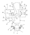
本発明の好ましい実施の形態を添付図面を参照しつつ説明する。図1は本発明の一実施の形態のメモリ機構付きチルトステアリング装置の分解斜視図である。図1を参照して、本メモリ機構付きチルトステアリング装置(以下では、単にチルトステアリング装置ともいう)は、上端に図示しないステアリングホイールが固定されるステアリングシャフト1を回転可能に支承するチューブからなるステアリングコラム2を備えている。ステアリングシャフト1はステアリングコラム2の下端から下方へ突出しており、ステアリングシャフト1の下端は自在継手3を介してギヤ側へ連結される。また、ステアリングシャフト1の下端近傍は、転がり軸受4により回転可能に支持されている。
【0015】
図1及びステアリング装置の概略側面図である図2を参照して、後述する固定ブラケット13の上板16から、横板5a及び縦板5bを有する略鉤形をなす固定板5が延設されており、縦板5bの下部に形成された球面状をなす支持孔6に、上記転がり軸受4の外輪4aが球面支持されている。すなわち球面状をなす支持孔6の球面の中心が、チルト中心Cとなり、このチルト中心Cの回りにステアリングシャフト1及びステアリングコラム2が揺動可能に支持されている。
【0016】
図1を参照して、5cは縦板5bに湾曲状に設けられたエネルギ吸収部であり、ステアリングホイールが受ける衝撃を吸収する。7はその固定端が縦板5bの下端に片持ち支持されると共に、その自由端にてステアリングシャフト1を持ち上げ方向に付勢するチルトアップばねである。チルトアップばね7は、チルトロックが解除されたときに、ステアリングホイールを最上位置まで跳ね上げる(チルトアップする)ためのものである。
【0017】
ステアリングコラム2の上部には、逆U字状をなすチルトブラケット8が溶接により固定されている。図1及びステアリング装置の横側面図である図2を参照して、チルトブラケット8は横方向に並んで相対向する一対の側板9,10とこれら側板9,10の上端を連結する上板11とを有しており、これら側板9,10の下端は内向きに曲げられ、ステアリングコラム2に溶接されている。各側板9,10には水平方向に延びる横長孔12が形成されている。
【0018】
13は車両に所定部に固定される固定ブラケットであり、この固定ブラケット13は下方に開放する溝形をなし、チルトブラケット8の各側板9,10の外面にそれぞれ沿う一対の側板14,15と、各側板14,15の上端部を連結する上板16とを備えている。各側板14,15には円弧状をなす縦長孔17がそれぞれ形成されている(図1では側板15の横長孔17のみを示してある。)。
【0019】
図1及び図2を参照して、18は固定ブラケット13及びチルトブラケット8の各側板9,10;14,15の横長孔12及び縦長孔17を一体的に挿通する操作軸である。横長孔12はいわゆるテレスコ調整に対応するためのものである。円弧状の縦長孔17は操作軸18がチルトブラケット8及びステアリングコラム2と一体にチルト中心Cの回りに揺動することを許容する。
【0020】
操作軸18の一端にはねじ部19が設けられ、フランジ付きナット20がねじ込まれる。一方、操作軸18の他端にはねじ部21が設けられナット22がねじ込まれる。ナット22と固定ブラケット13の側板15との間において操作軸18には、第1の部材としての一対のカムフォロワ23を一体に形成する操作レバー24と、各カムフォロワ23に対応する一対の駆動エリア26,27を有する第2の部材25とが挿通されている。
【0021】
カム機構を説明するための分解斜視図である図3を参照して、操作レバー24は、操作軸18を相対回動自在に挿通させる支持孔51の周囲にボス52を有しており、ボス52の第2の部材25側の端面53に上記一対のカムフォロワ23,23が形成されている。これら一対のカムフォロワ23,23は、ボス52の端面53に支持孔51を挟んで互いに対称な位置に配置される一対の突起からなり、これらの突起は放射方向に延びる直方体形状をなしている。
【0022】
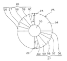
一方、図3及び第2のカム部材25の端面図である図4を参照して、第2の部材25の操作レバー24側の端面54には、操作軸18を相対回動自在に挿通させる支持孔55を挟んだ対称位置に、上記一対の駆動エリア26,27が配置されている。各駆動エリア26,27は操作レバー24の一の回転方向(締め込み方向)に沿って順次に並ぶ、第1の平坦部56、第1のカム部57、第2の平坦部58、第2のカム部59及び第3の平坦部60を備えている。図4では、各カムフォロワ23が各エリア26,27の第3の平坦部56に当接する状態を示してある。図1及び図3を参照して、第2の部材25は端面54の背面に二面幅部分28を形成しており、この二面幅部分28を側板15の縦長孔17に嵌め入れることにより、回動不能とされている。
【0023】
操作レバー24が回動されると、駆動エリア26,27に介してカムフォロワ23,23が相対回動するので、第2のカム部材25とフランジ付きナット20との間の間隔が増減される。その結果、固定ブラケット13の一対の側板14,15が上端を中心として撓み変形し、これにより、固定ブラケット13の側板14,15を、対応するチルトブラケット8の側板9,10に押圧してチルトロックを達成できる。また、上記と逆の動作で上記の押圧を解除してチルトロックを解除することができる。
【0024】
図5は操作レバー24の回転変位と、第2の部材25の軸方向への駆動量との関係を示す図である。図5を参照して、▲1▼,▲2▼,▲3▼,▲4▼及び▲5▼はそれぞれ、カムフォロワ23が第1の平坦部56、第1のカム部57、第2の平坦部58、第2のカム部59及び第3の平坦部60に当接する状態に対応している。
▲1▼ではチルトロック及び後述するメモリロックの双方が解除され、▲3▼ではメモリロックが達成されると共にチルトロックが解除される。また、▲5▼ではチルトロック及びメモリロックの双方が達成される。
【0025】
次いで、ステアリングホイールのチルトアップ前の位置を記憶するためのメモリ機構について説明する。
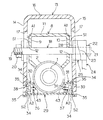
図1及び図1の操作軸18に沿う縦断面図である図6を参照して、固定ブラケット13の各側板14,15の下部同士は、連結部材29により互いに連結されている。この連結部材29は、上記カム部材23,25による側板14,15の曲げ変形を許容しつつ、両側板14,15を互いに連結する。連結部材29は、外方へ開く一対の溝形部30,31同士を横板32にて連結したものからなる。各溝形部30,31は縦板からなるウェブ33とウェブ33の上下端からそれぞれ外方へ延びる一対の円弧板からなる連結突起34とを有している。各一対の連結突起34は各側板14,15の下部に形成された各一対の円弧状溝35に遊嵌され、両側板14,15間の間隔が増減するような側板14,15の変位のみを許容する。また、ウェブ33の中央部には、後述するチルトメモリの支軸を挿通させる支持孔36が形成されている。
【0026】
37はステアリングホイールのチルトアップ前の位置を記憶するためのチルトメモリである。このチルトメモリ37は相対向する第1及び第2のアーム38,39と、これらアーム38,39同士を互いに連結する連結板40と、この連結板40の中央部から折り曲げ形成されてステアリングコラム2を受ける受け部41とを有している。
【0027】
各アーム38,39の先端部42にはそれぞれ内向きに支軸43が突出形成されている。各支軸43は、固定ブラケット13の側板14,15によって支持された連結部材29の対応する支持孔36に挿通されることにより、チルトメモリ37が支軸43の回りに回動自在に支持される。
44は、支軸43の回りを取り巻くねじりコイルばねからなり、チルトメモリ37をその受け部41がステアリングコラム2に接するように回動付勢する付勢ばねである(図1では、アーム39側の支軸43に対応する付勢ばね44のみを示してある。)。この付勢ばね44の一端45はチルトメモリ37のアーム39,40の係合溝46に係合され、他端47は連結部材29の各ウェブ33に形成した係合溝(図示せず)に係合される。
【0028】
固定ブラケット13の各側板14,15の対向面は、チルトブラケット8の対応する側板9,10に押圧されることによりチルトロックを達成する第1の領域A1を有し、またチルトメモリ37の対応する側板38,39に押圧されることによりメモリロックを達成する第2の領域A2を有している。
次いで、図6〜図8を参照して、チルトロック及びメモリロックの達成と解除について説明する。図6〜図8においては、第2の部材25の駆動エリア26,27とカムフォロワ23との係合については模式的に示してある。
【0029】
図6は操作レバー24を最も緩めた状態を模式的に示しており、図5の▲1▼のエリアに対応する。この状態では、第1の領域A1とチルトブラケット8の側板9,10との間に隙間S1が生じ、第2の領域A2とチルトメモリ37の側板38,39との間に隙間S2が生じている。これにより、チルトロック及びメモリロックの双方が解除されている。
【0030】
次いで、図7は操作レバー24を最も締め込んだ状態を模式的に示しており、図5の▲5▼のエリアに対応する。この状態では、第1の領域A1がチルトブラケット8の側板9,10に押圧されて摩擦係合し、第2の領域A2がチルトメモリ37の側板38,39に押圧されて摩擦係合している。これにより、チルトロック及びメモリロックの双方が達成されている。
【0031】
次いで、図8は操作レバー24を図6と図7の中間の回動位置まで戻した状態を示しており、図5の▲3▼のエリアに対応する。この状態では、第1の領域A1とチルトブラケット8の側板9,10との間に隙間S3が生じ、第2の領域A2とチルトメモリ37の側板38,39とは摩擦係合している。これにより、メモリロックは維持した状板でチルトロックのみが解除されている。
【0032】
したがって、操作レバー24を、図7から図8の間で(すなわち図5の▲3▼〜▲5▼のエリアで)操作すると、チルトロックのみを達成したり解除したりすることができる。このようにしてメモリロックを維持した状態でチルトロックを解除すると、ステアリングホイールがチルトアップばね7によってチルトアップされる。このとき、メモリロックは解除されておらず、チルトメモリ37がチルトアップ前の位置に固定されているので、ステアリングホイールを下降させると、ステアリングコラム2がチルトメモリ37の受け部41によって受けられて、自動的にチルトアップ前の位置に復帰させることができる。
【0033】
一方、操作レバー24を図6の状態まで操作して、メモリロックを解除すると、チルトメモリ37がチルト調節時に揺動されるステアリングコラム2に追従して自在に動くことになり、異なる運転者の体格等に合わせたチルトメモリの設定が可能となる。
本態様によれば、単一の操作レバー24の操作で、チルトロック及びメモリロックとその解除を個別に達成でき、構造が簡単で操作性が良い。また、各ロックに摩擦係合を用いるので、各ロックのレイアウトの自由度が高い。
【0034】
また、駆動エリア26,27いわゆる2段カムを用い、カム部57,59を挟んだ各平坦部56,58,60にて、ユーザが操作レバー24を介して各ロックの達成や解除の感触を得ることができ、操作感が良い。
なお、本発明は上記実施の形態に限定されるものではなく、第2の部材25にカムフォロワ23を設け、操作レバー24に駆動エリア26,27を設けるようにしても良い。
【0035】
また、第1の部材としてのカムフォロワ23を操作レバー24と別体に設けて、この第1の部材を操作軸18又は操作レバー24に一体回動するように連結しても良い。
また、第1及び第2の部材に代えて、互いにねじ結合し相対回転により軸長方向の長さを可変する一対のねじ部材を用いても良い。その他、本発明の範囲で種々の変更を施すことができる。
【0036】
【発明の効果】
請求項1記載の発明では、単一の操作レバーの操作で、チルトロック及びメモリロックとその解除を個別に達成でき、構造が簡単で操作性が良い。また、各ロックに摩擦係合を用いるので、各ロックのレイアウトの自由度が高い。
請求項2記載の発明では、操作レバーを回動すると、第1及び第2の部材が相対回動し、ねじ又はカムの働きで第1及び第2の部材が互いに他を軸長方向に押圧し、固定ブラケットの側板を弾性変形させることができる。
【0037】
請求項3記載の発明では、いわゆる2段カムとなり、操作レバーを操作するユーザに、チルトロックやメモリロックの達成及び解除の感触を与えることができる。
【図面の簡単な説明】
【図1】本発明の一実施の形態のメモリ機構付きチルトステアリング装置の分解斜視図である。
【図2】チルトステアリング装置の一部破断概略側面図である。
【図3】チルトロック及びメモリロックを達成するカム機構の概略分解斜視図である。
【図4】駆動エリアを含む第2の部材の端面図である。
【図5】操作レバーの回動変位と第2の部材の駆動量との関係を示す図である。
【図6】チルトステアリング装置の要部の縦断面図であり、チルトロック及びメモリロックの双方が解除された状態を示している。
【図7】チルトステアリング装置の要部の縦断面図であり、チルトロック及びメモリロックの双方が達成された状態を示している。
【図8】チルトステアリング装置の要部の縦断面図であり、チルトロックが解除されメモリロックが達成された状態を示している。
【符号の説明】
1 ステアリングシャフト
2 ステアリングコラム
C チルト中心
7 チルトアップばね
8 チルトブラケット
9,10 側板
12 横長孔
13 固定ブラケット
14,15 側板
17 縦長孔
18 操作軸
23 カムフォロワ(第1の部材)
24 操作レバー
25 第2の部材
26,27 駆動エリア
29 連結部材
37 チルトメモリ
38,39 側板
40 連結板
41 受け部
43 支軸
44 付勢ばね
53,54 端面
56 第1の平坦部
57 第1のカム部
58 第2の平坦部
59 第2のカム部
60 第3の平坦部[0001]
BACKGROUND OF THE INVENTION
The present invention memorizes the position of the steering wheel tilt-adjusted to a desired height, and automatically returns it to the desired height position when the tilted-up steering wheel is lowered. The present invention relates to a tilt steering device with a memory mechanism.
[0002]
[Prior art]
In a tilt steering device that can change the height of the steering wheel according to the physique and driving posture of the driver, the steering wheel is lifted up to the uppermost position by operating the lever so that the steering wheel does not interfere with getting on and off. (Tilt up) to facilitate getting on and off.
[0003]
Some devices of this type are provided with a memory for storing the height position of the steering wheel that has been tilt-adjusted before tilt-up. That is, when the steering wheel is lowered after getting on and off in a state where the steering wheel is tilted up by the elasticity of the spring, it can be automatically returned to the stored height position.
[0004]
For example, the steering column is composed of an upper tube and a lower tube, and the tilt bracket fixed to the lower end of the upper tube can swing around the tilt center axis provided on the fixed bracket fixed to the upper end of the lower tube There is a so-called folding type tilt steering device that is connected. In this type of middle folding type, the pole mounted on the tilt bracket is engaged with a ratchet provided on the fixed bracket to achieve tilt lock. As a memory mechanism, there is a memory mechanism in which a tilt cam assembled to a tilt bracket is engaged with a memory pin fixed to a ratchet when the tilt bracket swings downward (for example, Japanese Patent Laid-Open No. 5-116634). See the official gazette).
[0005]
[Problems to be solved by the invention]
In the device disclosed in the above publication, tilt lock and release thereof are performed by operating a tilt lever that is rotatable about a tilt central axis, and the memory position of the memory mechanism is changed by positioning provided separately from the tilt lever. This is performed by changing the rotation position of the tilt cam by a mechanism. As described above, since the tilt adjustment and the memory adjustment are performed by separate operation members, the structure becomes complicated and the compactness is hindered.
[0006]
On the other hand, it is very difficult to provide a memory mechanism in a so-called foot-on-tilt tilt steering device also called a simple tilt method, and such a device has not been realized in practice.
However, even in this type of simple tilt type tilt steering device, it is desired to mount a memory mechanism.
[0007]
The present invention has been made in view of the above problems, and is to provide a tilt steering device with a memory mechanism that is simple in structure and easy to operate in a so-called simple tilt type.
[0008]
[Means for Solving the Problems]
As a problem-solving means for achieving the above object, an aspect of the invention according to
[0009]
In this aspect, since the amount of elastic deformation of the fixed bracket is large when the driving amount by the driving member is maximum, the first and second regions are frictionally engaged with the tilt bracket and the tilt memory, respectively, and the tilt lock and the memory lock. Has been achieved.
When the operating lever is rotated from this state to reduce the driving amount by the driving member by a predetermined amount, only the frictional engagement between the first region and the tilt bracket is released, and only the tilt lock is released. At this time, the memory lock is not released, and the tilt memory is fixed at the position before the tilt up. Therefore, when the steering wheel is lowered, the steering column is received by the tilt memory and automatically before the tilt up. It can be returned to the position.
[0010]
When the operation lever is further rotated to further reduce the amount of drive by the drive member, the memory lock is also released, so that the tilt memory moves freely following the steering column that is swung during tilt adjustment.
Tilt lock and memory lock and their release can be achieved individually by operating a single control lever, and the structure is simple and operability is good. Further, since friction engagement is used for each lock, the degree of freedom in layout of each lock is high.
[0011]
According to a second aspect of the present invention, in the first aspect, the driving member is rotated integrally with the operation lever by a first member that is non-rotatably supported by the fixed bracket, and the first member is moved to the fixed bracket side. And a second member that presses toward each other. These first and second members are arranged side by side on the same axis as the operation shaft, and are connected to each other by a screw or a cam surface.
[0012]
In this aspect, the first and second members rotate relative to each other, and the first and second members press each other in the axial length direction by the action of a screw or a cam to elastically deform the side plate of the fixed bracket.
According to a third aspect of the present invention, in the second aspect of the present invention, at least one of the opposing surfaces of the first and second members has a first flat portion along the rotation direction of the operation lever, respectively. A first cam portion, a second flat portion, a second cam portion, and a third flat portion are included.
[0013]
In this aspect, it becomes a so-called two-stage cam, in a state where the tilt lock and the memory lock are achieved with the rotation of the operation lever, a state where only the tilt lock is achieved, and a state where both locks are released, Each holding force can be applied. It is possible to give the user who operates the operation lever the feeling of reaching each state.
[0014]
DETAILED DESCRIPTION OF THE INVENTION
Preferred embodiments of the present invention will be described with reference to the accompanying drawings. FIG. 1 is an exploded perspective view of a tilt steering apparatus with a memory mechanism according to an embodiment of the present invention. Referring to FIG. 1, a tilt steering device with a memory mechanism (hereinafter, also simply referred to as a tilt steering device) includes a steering tube that rotatably supports a
[0015]
Referring to FIG. 1 and FIG. 2 which is a schematic side view of the steering device, a
[0016]
Referring to FIG. 1,
[0017]
A
[0018]
[0019]
Referring to FIGS. 1 and 2,
[0020]
A threaded
[0021]
Referring to FIG. 3 which is an exploded perspective view for explaining the cam mechanism, the
[0022]
On the other hand, referring to FIG. 3 and FIG. 4 which is an end view of the
[0023]
When the
[0024]
FIG. 5 is a diagram showing the relationship between the rotational displacement of the
In (1), both the tilt lock and the memory lock described later are released, and in (3), the memory lock is achieved and the tilt lock is released. In (5), both tilt lock and memory lock are achieved.
[0025]
Next, a memory mechanism for storing the position of the steering wheel before tilting will be described.
Referring to FIG. 6, which is a longitudinal sectional view along the
[0026]
[0027]
A
44 is a torsion coil spring that surrounds the
[0028]
The opposing surfaces of the
Next, the achievement and release of tilt lock and memory lock will be described with reference to FIGS. 6 to 8, the engagement between the
[0029]
FIG. 6 schematically shows a state in which the
[0030]
Next, FIG. 7 schematically shows a state in which the
[0031]
Next, FIG. 8 shows a state in which the
[0032]
Therefore, when the
[0033]
On the other hand, when the
According to this aspect, the tilt lock and the memory lock and their release can be achieved individually by operating the
[0034]
In addition, the
The present invention is not limited to the above embodiment, and the
[0035]
Further, the
Further, instead of the first and second members, a pair of screw members that are screw-coupled to each other and whose length in the axial length direction can be changed by relative rotation may be used. In addition, various modifications can be made within the scope of the present invention.
[0036]
【The invention's effect】
According to the first aspect of the present invention, the tilt lock and the memory lock and the release thereof can be achieved individually by operating the single operation lever, and the structure is simple and the operability is good. Further, since friction engagement is used for each lock, the degree of freedom in layout of each lock is high.
According to the second aspect of the present invention, when the operation lever is rotated, the first and second members are rotated relative to each other, and the first and second members press each other in the axial length direction by the action of a screw or a cam. Then, the side plate of the fixing bracket can be elastically deformed.
[0037]
According to the third aspect of the present invention, a so-called two-stage cam is provided, and a user who operates the operation lever can be given a feeling of achievement and release of tilt lock and memory lock.
[Brief description of the drawings]
FIG. 1 is an exploded perspective view of a tilt steering device with a memory mechanism according to an embodiment of the present invention.
FIG. 2 is a partially cutaway schematic side view of the tilt steering device.
FIG. 3 is a schematic exploded perspective view of a cam mechanism that achieves tilt lock and memory lock.
FIG. 4 is an end view of a second member including a drive area.
FIG. 5 is a diagram illustrating a relationship between a rotational displacement of an operation lever and a driving amount of a second member.
FIG. 6 is a longitudinal sectional view of a main part of the tilt steering device, showing a state in which both the tilt lock and the memory lock are released.
FIG. 7 is a longitudinal sectional view of a main part of the tilt steering device, showing a state in which both tilt lock and memory lock are achieved.
FIG. 8 is a longitudinal sectional view of a main part of the tilt steering device, showing a state where the tilt lock is released and the memory lock is achieved.
[Explanation of symbols]
DESCRIPTION OF
24
Claims (3)
固定ブラケット及びチルトブラケットの一方に設けられた横長孔と他方に設けられた円弧状の縦長孔を回動可能に挿通した状態で、固定ブラケットに対するチルトブラケットの揺動を許容する操作軸と、
この操作軸の回りに回転し且つ手動操作される操作レバーと、
上記固定ブラケットに操作軸と平行な支軸の回りに揺動自在に支持され、付勢ばねによって付勢されてチルトブラケットの揺動に追従可能であって、ステアリングコラムを受ける位置に固定されるチルトメモリと、
固定ブラケットに設けられた側板であって、上端を固定端とし下端を自由端として弾性変形可能な片持ち状の側板と、
固定ブラケットの上記片持ち状の側板の側面の、固定端と自由端との間の部分に設けられ、チルトブラケットの側板の側面に対向する第1の領域と、
固定ブラケットの上記片持ち状の側板の側面の、第1の領域よりも自由端側の部分に設けられ、チルトメモリの側板の側面に対向する第2の領域と、
操作レバーの回動に伴って上記固定ブラケットの側板を弾性変形させて、上記第1及び第2の領域を対応するチルトブラケットの側板の側面及びチルトメモリの側板の側面に押圧する駆動部材とを備え、
上記第1の領域がチルトブラケットの側板の側面に摩擦係合してチルトロックを達成するまでの駆動部材による駆動量よりも、上記第2の領域がチルトメモリの側板の側面に摩擦係合してメモリロックを達成するまでの駆動部材による駆動量が小さくされていることを特徴とするメモリ機構付きチルトステアリング装置。The lower end of the tilt center is supported around the center of the tilt so that the steering shaft can be pivoted, the tilt bracket fixed to the steering column, and the tilt bracket can be tilted by releasing the fixed bracket. In the tilt steering device that can tilt the steering wheel up to the top dead center by the up spring,
An operating shaft that allows the tilt bracket to swing relative to the fixed bracket in a state in which a horizontally long hole provided in one of the fixed bracket and the tilt bracket and an arcuate vertical long hole provided in the other are rotatably inserted;
An operation lever that rotates around the operation axis and is manually operated;
The fixed bracket is supported so as to be swingable around a support shaft parallel to the operation shaft, and is biased by a biasing spring so as to follow the swing of the tilt bracket and is fixed at a position for receiving the steering column. Tilt memory,
A side plate provided on the fixed bracket, the cantilevered side plate being elastically deformable with the upper end as a fixed end and the lower end as a free end;
Side of the cantilevered plate fixing bracket, setting a portion between the fixed end and a free end vignetting, a first region pairs toward the side of the side plate of Chirutoburake' bets,
A second region provided on a portion of the side surface of the cantilevered side plate of the fixed bracket on a side closer to a free end than the first region, and facing the side surface of the side plate of the tilt memory ;
With the rotation of the operation lever is elastically deformed side plate of the fixing bracket, and a driving member for pressing said first and second regions on the side surface of the side plate side and tilt memory side plates of the corresponding tilt bracket Prepared,
The second region is frictionally engaged with the side surface of the side plate of the tilt memory rather than the driving amount by the driving member until the first region is frictionally engaged with the side surface of the side plate of the tilt bracket to achieve tilt lock. The tilt steering device with a memory mechanism is characterized in that the drive amount by the drive member until the memory lock is achieved is reduced.
Priority Applications (1)
| Application Number | Priority Date | Filing Date | Title |
|---|---|---|---|
| JP17427999A JP3673429B2 (en) | 1999-06-21 | 1999-06-21 | Tilt steering device with memory mechanism |
Applications Claiming Priority (1)
| Application Number | Priority Date | Filing Date | Title |
|---|---|---|---|
| JP17427999A JP3673429B2 (en) | 1999-06-21 | 1999-06-21 | Tilt steering device with memory mechanism |
Publications (2)
| Publication Number | Publication Date |
|---|---|
| JP2001001914A JP2001001914A (en) | 2001-01-09 |
| JP3673429B2 true JP3673429B2 (en) | 2005-07-20 |
Family
ID=15975894
Family Applications (1)
| Application Number | Title | Priority Date | Filing Date |
|---|---|---|---|
| JP17427999A Expired - Fee Related JP3673429B2 (en) | 1999-06-21 | 1999-06-21 | Tilt steering device with memory mechanism |
Country Status (1)
| Country | Link |
|---|---|
| JP (1) | JP3673429B2 (en) |
Cited By (1)
| Publication number | Priority date | Publication date | Assignee | Title |
|---|---|---|---|---|
| KR102151218B1 (en) * | 2019-04-04 | 2020-09-02 | 이래에이엠에스 주식회사 | Adjustable steering column assembly |
Families Citing this family (12)
| Publication number | Priority date | Publication date | Assignee | Title |
|---|---|---|---|---|
| DE19916260A1 (en) * | 1999-04-12 | 2000-10-26 | Rudolf Kohlert | Support element for clamping workpieces |
| JP2003112633A (en) * | 2001-10-04 | 2003-04-15 | Koyo Seiko Co Ltd | Steering device |
| KR100746685B1 (en) * | 2002-03-25 | 2007-08-06 | 주식회사 만도 | Shock Absorber of Vehicle Steering Column |
| KR100746723B1 (en) * | 2002-07-16 | 2007-08-06 | 주식회사 만도 | Shock Absorber of Vehicle Steering Column |
| KR100746674B1 (en) * | 2002-09-30 | 2007-08-06 | 주식회사 만도 | Shock Absorber of Steering System |
| DE102004007554B4 (en) * | 2004-02-17 | 2008-10-02 | Daimler Ag | Steering column assembly for a motor vehicle |
| JP2006124947A (en) * | 2004-10-26 | 2006-05-18 | Light Boy Co Ltd | Extensible strut and floodlight having extensible strut |
| JP5003040B2 (en) * | 2006-07-12 | 2012-08-15 | 日本精工株式会社 | Steering device |
| US8919816B2 (en) | 2010-10-18 | 2014-12-30 | Aisin Seiki Kabushiki Kaisha | Steering apparatus for a vehicle |
| EP2631155B1 (en) | 2010-10-18 | 2014-11-26 | Aisin Seiki Kabushiki Kaisha | Steering apparatus for a vehicle |
| JP2012096691A (en) * | 2010-11-02 | 2012-05-24 | Aisin Seiki Co Ltd | Tilt steering system for vehicle |
| JP6323707B2 (en) * | 2014-01-27 | 2018-05-16 | 株式会社ジェイテクト | Lock device and steering device including the same |
-
1999
- 1999-06-21 JP JP17427999A patent/JP3673429B2/en not_active Expired - Fee Related
Cited By (1)
| Publication number | Priority date | Publication date | Assignee | Title |
|---|---|---|---|---|
| KR102151218B1 (en) * | 2019-04-04 | 2020-09-02 | 이래에이엠에스 주식회사 | Adjustable steering column assembly |
Also Published As
| Publication number | Publication date |
|---|---|
| JP2001001914A (en) | 2001-01-09 |
Similar Documents
| Publication | Publication Date | Title |
|---|---|---|
| JP3673429B2 (en) | Tilt steering device with memory mechanism | |
| US4594909A (en) | Tiltable steering mechanism | |
| US4950032A (en) | Seat having vertically movable lumber support | |
| US5531317A (en) | Tilt-type steering column device | |
| US5078022A (en) | Tilt type steering apparatus | |
| JPH0612711Y2 (en) | Sheet | |
| JPH061003Y2 (en) | Sheet | |
| EP1132253B1 (en) | Lever apparatus | |
| JP3865549B2 (en) | Tilt steering device with memory mechanism | |
| JPH0630027Y2 (en) | Sheet | |
| JP2001233222A (en) | Tilt telescopic steering device with memory mechanism | |
| JP3716630B2 (en) | Tilt-type steering device | |
| JP3689594B2 (en) | Tilt steering device | |
| JPH085898Y2 (en) | Tilt-type steering device with flip-up mechanism | |
| JP4280954B2 (en) | Tilt telescopic steering device with memory mechanism | |
| KR20070005799A (en) | Steering wheel and instrument panel tilting device for agricultural vehicles | |
| JPH0643186B2 (en) | Tilt steering device with memory mechanism | |
| JPH0638769B2 (en) | Lumber support device | |
| JP2601373Y2 (en) | Tilt steering device | |
| JPH0220141Y2 (en) | ||
| JPH0367778A (en) | tilt steering device | |
| JP3171306B2 (en) | Turnover lever remote control rearview mirror | |
| JPH0550283B2 (en) | ||
| JP3466544B2 (en) | Ratchet lever mechanism | |
| KR100738378B1 (en) | Tilt lever and steering column of automobile with same |
Legal Events
| Date | Code | Title | Description |
|---|---|---|---|
| A977 | Report on retrieval |
Free format text: JAPANESE INTERMEDIATE CODE: A971007 Effective date: 20041207 |
|
| A131 | Notification of reasons for refusal |
Free format text: JAPANESE INTERMEDIATE CODE: A131 Effective date: 20050106 |
|
| A521 | Written amendment |
Free format text: JAPANESE INTERMEDIATE CODE: A523 Effective date: 20050307 |
|
| TRDD | Decision of grant or rejection written | ||
| A01 | Written decision to grant a patent or to grant a registration (utility model) |
Free format text: JAPANESE INTERMEDIATE CODE: A01 Effective date: 20050412 |
|
| A61 | First payment of annual fees (during grant procedure) |
Free format text: JAPANESE INTERMEDIATE CODE: A61 Effective date: 20050422 |
|
| R150 | Certificate of patent (=grant) or registration of utility model |
Free format text: JAPANESE INTERMEDIATE CODE: R150 |
|
| S533 | Written request for registration of change of name |
Free format text: JAPANESE INTERMEDIATE CODE: R313533 |
|
| R350 | Written notification of registration of transfer |
Free format text: JAPANESE INTERMEDIATE CODE: R350 |
|
| FPAY | Renewal fee payment (prs date is renewal date of database) |
Free format text: PAYMENT UNTIL: 20080428 Year of fee payment: 3 |
|
| FPAY | Renewal fee payment (prs date is renewal date of database) |
Year of fee payment: 4 Free format text: PAYMENT UNTIL: 20090428 |
|
| FPAY | Renewal fee payment (prs date is renewal date of database) |
Year of fee payment: 4 Free format text: PAYMENT UNTIL: 20090428 |
|
| FPAY | Renewal fee payment (prs date is renewal date of database) |
Year of fee payment: 5 Free format text: PAYMENT UNTIL: 20100428 |
|
| LAPS | Cancellation because of no payment of annual fees |