EP2631004A2 - Filter für ein Rohr - Google Patents
Filter für ein Rohr Download PDFInfo
- Publication number
- EP2631004A2 EP2631004A2 EP13156036.9A EP13156036A EP2631004A2 EP 2631004 A2 EP2631004 A2 EP 2631004A2 EP 13156036 A EP13156036 A EP 13156036A EP 2631004 A2 EP2631004 A2 EP 2631004A2
- Authority
- EP
- European Patent Office
- Prior art keywords
- filter
- pipe
- filter surface
- faces
- sectional area
- Prior art date
- Legal status (The legal status is an assumption and is not a legal conclusion. Google has not performed a legal analysis and makes no representation as to the accuracy of the status listed.)
- Withdrawn
Links
Images


Classifications
-
- B—PERFORMING OPERATIONS; TRANSPORTING
- B01—PHYSICAL OR CHEMICAL PROCESSES OR APPARATUS IN GENERAL
- B01D—SEPARATION
- B01D39/00—Filtering material for liquid or gaseous fluids
- B01D39/14—Other self-supporting filtering material ; Other filtering material
-
- B—PERFORMING OPERATIONS; TRANSPORTING
- B01—PHYSICAL OR CHEMICAL PROCESSES OR APPARATUS IN GENERAL
- B01D—SEPARATION
- B01D45/00—Separating dispersed particles from gases or vapours by gravity, inertia, or centrifugal forces
- B01D45/04—Separating dispersed particles from gases or vapours by gravity, inertia, or centrifugal forces by utilising inertia
- B01D45/08—Separating dispersed particles from gases or vapours by gravity, inertia, or centrifugal forces by utilising inertia by impingement against baffle separators
-
- B—PERFORMING OPERATIONS; TRANSPORTING
- B01—PHYSICAL OR CHEMICAL PROCESSES OR APPARATUS IN GENERAL
- B01D—SEPARATION
- B01D46/00—Filters or filtering processes specially modified for separating dispersed particles from gases or vapours
- B01D46/0002—Casings; Housings; Frame constructions
- B01D46/0012—In-line filters
-
- B—PERFORMING OPERATIONS; TRANSPORTING
- B01—PHYSICAL OR CHEMICAL PROCESSES OR APPARATUS IN GENERAL
- B01D—SEPARATION
- B01D50/00—Combinations of methods or devices for separating particles from gases or vapours
- B01D50/20—Combinations of devices covered by groups B01D45/00 and B01D46/00
-
- B—PERFORMING OPERATIONS; TRANSPORTING
- B01—PHYSICAL OR CHEMICAL PROCESSES OR APPARATUS IN GENERAL
- B01D—SEPARATION
- B01D2275/00—Filter media structures for filters specially adapted for separating dispersed particles from gases or vapours
- B01D2275/20—Shape of filtering material
Definitions
- the present invention concerns a filter for a pipe. More particularly, but not exclusively, this invention concerns a filter comprising an attachment portion for attaching to the pipe, and a filter surface for presentation to and filtering of an oncoming flow of the pipe.
- the invention also concerns a pipe for transporting an oncoming flow, wherein the pipe is provided with a filter surface across the cross-sectional area of the pipe and an aircraft with such a filter or pipe.
- the invention also concerns a method of filtering an oncoming flow of a pipe.
- An aircraft fuel system for example, has a number of flow devices that use suction pressure to induce flow out of a fuel tank and into a pipe. These flow devices often contain small diameter pipes and nozzles that can become blocked by debris induced into the system from the fuel tanks.
- Current pipe filters comprise a mesh screen over the pipe inlet. The mesh screen can be either flat across the pipe inlet or can be slightly rounded to form a convex end on the pipe inlet.
- mesh screen can cause a variety of problems.
- the mesh screen inevitably blocks some of the pipe inlet area and so causes a pressure drop across the pipe inlet and a loss of efficiency.
- partial blockage of the filter results in a further pressure drop across the filter and further loss of efficiency.
- a debris particle that is larger than the pipe inlet diameter can be held against the mesh screen by suction pressure and can completely block the inlet.
- the mesh screens are susceptible to ice formation, especially where the pipe inlet is located in an area of relatively high water concentration, for example in the inlet to a water scavenge jet pump. Ice formation can also lead to a partial or full blockage of the pipe.
- larger-holed mesh screens can be used but these can cause larger debris particles to pass through the filter and can cause blockage in the systems.
- Blockages are often only found when a problem occurs and are very difficult and time consuming to discover. Furthermore, cleaning the blockages, for example for filters in aircraft fuel tank systems, requires entry into the aircraft fuel tank. This is expensive and raises several health and safety concerns.
- the present invention seeks to mitigate the above-mentioned problems. Alternatively or additionally, the present invention seeks to provide an improved filter or pipe or an improved method of filtering an oncoming flow of a pipe.
- the present invention provides, according to a first aspect, a filter for a pipe, the filter comprising an attachment portion for attaching to the pipe, and a filter surface for presentation to and filtering of an oncoming flow of the pipe, wherein the filter surface has at least one pointed apex for protruding into the oncoming flow.
- the pointed apex deflects large debris particles away from the filter and prevents large debris particles from "sitting" on the filter surface. This prevents the filter being partially or completely blocked by a large debris particle.
- the filter has a diameter in the region of between 8 and 80 mm, preferably between 10 and 30 mm, and more preferably approximately 20 mm.
- the filter is for use with a pipe with a diameter in the region of between 5 and 50 mm, preferably between 5 and 20 mm and more preferably approximately 12 mm.
- the filter and/or pipe are designed for dealing with flows in the region of between 3 and 1000 litres/minute, preferably between 10 and 30 litres/minute and more preferably approximately 20 litres/minute.
- the filter is preferably designed to filter a flow to remove debris with a diameter in the region of between 2 mm and 50 mm and more preferably between of 2 mm and 10 mm.
- the apex faces substantially the opposite direction to the direction of the oncoming flow. This provides maximum potential for breaking up debris particles and preventing them for "sitting" on the filter surface.
- the filter surface is in the form of a pyramidal shape with a number of substantially triangular faces.
- the pyramidal shape is generally in the form of a cone, except with a number of faces around the apex rather than a single smooth conical surface.
- the faces are generally triangular, with a rounded convex base corresponding to what would have been the circular base of the cone.
- At least one of the faces of the filter surface is open to allow the oncoming flow to pass through that face of the filter surface and wherein at least one of the faces is substantially solid, thereby deflecting debris from the filter surface.
- the solid and open faces of the filter surface are alternately circumferentially disposed around the apex. Hence, any smaller debris particles can only block one face of the filter surface and do not cause a large pressure drop across the filter.
- the filter surface comprises plate edges or wires along the corner lengths of the pyramidal shape.
- the plate edges or wires act to break up large debris and prevent debris "sitting" on the filter surface.
- the plate edges or wires would also not be prone to ice formation.
- the filter surface has 4 or 8 faces. Having 8 faces, wherein there are equal numbers of solid and open faces, allows there to be 4 open faces. Having 4 faces, wherein the filter surface comprises plate edges or wire along the corner lengths of the pyramidal shape, also allows there to be 4 open faces.
- Having 4 open faces means a blockage of one of the open faces results in 75% of the filter surface still being available and hence, a manageable pressure drop.
- a larger number of faces would reduce the pressure drop from one face being blocked but would increase the likelihood of ice formation.
- a smaller number of faces would result in larger debris passing through the filter and a more significant pressure drop if one of the faces was blocked.
- the filter further comprises a mesh screen for further filtration of the oncoming flow. More preferably, further filtration is provided for oncoming flow that has passed through the open faces of the filter surface.
- the corner lengths of the pyramidal shape are concave. This means that the faces of the filter surface curve inwards and do not provide a flat area for a debris particle to "sit on”. In addition, if a debris particle did "sit" on the concave face, it would be held above the actual filter surface and be liable to be broken by the suction pressure.
- the filter is an inlet filter for a pipe and wherein the attachment portion is for attaching the filter surface across one end of the pipe.
- the cross-sectional area across the base of the filter surface is greater than the cross-sectional area of the attachment portion of the filter. This means that the filter surface is relatively large, and may be larger than the cross-sectional area of the pipe.
- the base of the filter surface when referring to the base of the filter surface, this should be understood to mean the dividing line between the region of the filter surface facing the oncoming flow and the region of the filter surface not facing the oncoming flow.
- the filter surface comprised two square based pyramids stuck base to base
- the surface of the foremost pyramid the pyramid with its apex protruding into the oncoming flow
- the surface of the rearmost pyramid the pyramid with its apex pointing away from the oncoming flow
- the base of the filter surface would be the base of the foremost pyramid.
- the region not facing the oncoming flow may not be considered to be part of the filter surface at all.
- the base of the filter surface can also be defined as the rearmost portion of the filter surface that faces the oncoming flow.
- the cross-sectional area across the base of the filter surface of the open faces of the pyramidal shape is greater than the cross-sectional area of the attachment portion of the filter. This means that the open filter area is relatively large, and may be larger than the cross-sectional area of the pipe.
- the cross-sectional area across the base of the filter surface of all except one of the open faces of the pyramidal shape is at least as big as the cross-sectional area of the attachment portion of the filter. This means that the open filter area, even when one open face is blocked, is relatively large, and may be larger than the cross-sectional area of the pipe inlet. This ensures that a partial blockage of one of the open faces of the filter surface does not give a pressure drop any greater than the pipe.
- the filter is for use in a pipe for a fuel system, a hydraulic system or an air system.
- the filter is for use in a pipe on an aircraft.
- the present invention also provides a pipe for transporting an oncoming flow, wherein the pipe is provided with a filter surface across the cross-sectional area of the pipe and wherein the filter surface has at least one pointed apex protruding along the longitudinal axis of the pipe.
- the cross-sectional area across the base of the filter surface is greater than the cross-sectional area of the pipe.
- the filter surface is in the form of a pyramidal shape with a number of substantially triangular open faces and the cross-sectional area across the base of the filter surface of the open faces of the pyramidal shape is greater than the cross-sectional area of the pipe.
- the cross-sectional area across the base of the filter surface of all except one of the open faces of the pyramidal shape is at least as big as the cross-sectional area of the pipe. This ensures that a partial blockage of one of the open faces of the filter surface does not give a pressure drop any greater than the pipe.
- the pipe is a pipe for a fuel system, a hydraulic system or an air system.
- the pipe is a pipe for use on an aircraft.
- the present invention also provides a fuel system, hydraulic system or air system of an aircraft, comprising a pipe in situ in the system, the pipe being as described above.
- the present invention also provides an aircraft comprising a filter or a pipe, as described above.
- the present invention also provides a method of filtering an oncoming flow of a pipe, the method comprising the steps of providing a pipe, providing the pipe with a filter surface across the cross-sectional area of the pipe, wherein the filter surface has at least one pointed apex, providing the oncoming flow to the pipe, wherein the pointed apex protrudes into the oncoming flow and acts to break up debris in the flow and/or deflect the debris away from the filter surface.
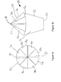
- FIGS 1a and 1b show a filter 20 according to a first embodiment of the invention.
- the filter 20 comprises a filter body 21 and a filter surface 25 on top of the filter body.
- the filter body 21 comprises a narrow circular base 23 for attaching to an inlet of a pipe.
- the filter body 21 has outwardly tapering sides 22 and a wider circular top portion 24.
- the filter surface 25 is attached on top of this top portion.
- the filter surface 25 is in the general shape of a pyramid with eight substantially triangular faces and a pointed apex 30.
- the eight faces are triangular, with a rounded convex base corresponding to the circular top portion 24.
- Four of the faces 31a, 31b, 31c, 31d are open faces and four of the faces 32a, 32b, 32c, 32d are solid faces.
- the open 31 and closed 32 faces are arranged alternately circumferentially around the apex 30.
- Figure 1c shows a side view of the filter 20 of Figures 1a and 1b in situ on an inlet 12 of a pipe 10.
- the pipe 10 has a diameter 11.
- the filter body 21 is attached at its base 23 to the pipe inlet 12.
- the diameter 11 of the pipe is the same as the diameter of the base 23 of the filter body 21.
- the arrow 13 represents the oncoming flow direction through the filter surface 25, through the filter body 21, through the pipe inlet 12 and into the pipe 10.
- oncoming flow 13 passes through the open faces 31 of the filter surface 25 into the pipe 10. Large pieces of debris in the flow 13 may impact on the pointed apex 30 and be broken up into smaller pieces of debris.
- the apex 30 may also deflect pieces of debris away from the filter surface 25.
- the solid faces 32 may also deflect and/or break up pieces of debris.
- Oncoming flow 13 is directed along the faces 31, 32 of the filter surface 25, causing the oncoming flow in these regions to be faster. This prevents ice formation on the filter surface 25.
- any pieces of debris that are caught on the filter surface 25 may cause one of the open faces 31a, for example, to be blocked. However, this still leaves the other three open faces 31b, 31c, 31d clear and so the pressure drop caused is not particularly large.
- the filter 20 is designed such that if one of the open faces 31a, for example, is completely blocked by debris, the three remaining open faces 31b, 31c, 31d still provide the same flow area as the pipe 10.
- the partially blocked filter 20 must provide a cross-sectional area at the base of the filter surface 25 (i.e. at the top portion 24 of the filter body 21) the same as the cross-sectional area of the pipe 10.
- the pipe 10 has a diameter 11 of 12 mm and therefore a cross-sectional area (A p ) of 113 mm 2 . Therefore the total base area of three of the open faces 31b, 31c, 31d must be A p . As the open faces 31 each have the same area, they must each have a base area (A f ) of 37.7 mm 2 (113 mm 2 / 3) .
- FIGS 2a and 2b show a filter 120 according to a second embodiment of the invention.
- the filter 120 comprises a filter body 121 and a filter surface 125 on top of the filter body.
- the filter body 121 comprises a narrow circular base 123 for attaching to an inlet of a pipe.
- the filter body 121 has outwardly tapering sides 122 and a wider circular top portion 124.
- the filter surface 125 is attached on top of this top potion.
- the filter surface 125 is in the general shape of a pyramid with four substantially triangular faces 133a, 133b, 133c, 133d and a pointed apex 130.
- the four faces 133 are triangular, with a rounded convex base corresponding to the circular top portion 124.
- the four corner lines 134a, 134b, 134c, 134d of the four faces 133 are concave, inwards towards the centre of the filter body 121.
- the filter surface 125 is the form of a concave pyramidal shape.
- the four faces 133a, 133b, 133c, 133d are open faces.
- the four corner lines 134a, 134b, 134c, 134d are each provided with a wire running along the corner lines from the apex 30 to the outside diameter of the top portion 124 of the filter body 121.
- oncoming flow passes through the open faces 133 of the filter surface 125 into the pipe.
- Large pieces of debris in the flow may impact on the pointed apex 130 and be broken up into smaller pieces of debris.
- the apex 130 may also deflect pieces of debris away from the filter surface 125.
- the wires on the corner lines 134 of the filter surface 125 may also deflect and/or break up pieces of debris.
- Oncoming flow is directed along the concave faces of the filter surface 125, causing the oncoming flow in these regions to be faster. This prevents ice formation on the filter surface 125.
- any pieces of debris that are caught on the filter surface 125 may cause one of the open faces 133a, for example, to be blocked. However, this still leaves the other three open faces 133b, 133c, 133d clear and so the pressure drop caused is not particularly large.
- the filter 120 is designed such that if one of the open faces 133a, for example, is completely blocked by debris, the three remaining open faces 133b, 133c, 133d still provide the same flow area as the pipe.
- the partially blocked filter must provide a cross-sectional area at the base of the filter surface 125 (i.e. at the top portion 124 of the filter body 121) the same as the cross-sectional area of the pipe.
- the pipe has a diameter of 12 mm and therefore a cross-sectional area (A p ) of 113 mm 2 . Therefore the total base area of three of the open faces 133b, 133c, 133d must be A p . As the open faces 133 each have the same area, they must each have a base area (A f ) of 37.7 mm 2 (113 mm 2 / 3).
- the total cross-sectional area at the base of the filter surface 125 (i.e. at the top portion 124 of the filter body 121), call this A b , must be 151 mm 2 (4 * 37.7 mm 2 ).
- the tapered sides 122 of the filter body 121 taper from a diameter of 12 mm at the pipe inlet / narrow circular base 123 of the filter body 121 to a diameter of 13.8 mm at the base of the filter surface 125 /top portion 124 of the filter body 121.
- This (13.8 mm) is smaller than the diameter of the base of the filter surface 25 of the first embodiment (19.6 mm). This is because there are no solid faces 32 making up the filter surface of this second embodiment.
- a mesh screen could also be used with either of the two embodiments.
- a mesh screen could be used as a secondary filter behind the filter 20 or 120.
- a mesh screen could, for example, be used behind the open faces 31 or 133 of the filters 20 or 120.
- the faces 31, 32 of the pyramidal shape of the first embodiment may be concave, as opposed to being straight between the apex 30 and the outside diameter of the top portion 24 of the filter body 21. This would provide a filter surface similar in shape to the filter surface 125 of the second embodiment.
- the wires at the corner lines 134 of the pyramidal shape of the second embodiment may not be concave and could simply be straight wires from the apex 130 to the outside diameter of the top portion 124 of the filter body 121. This would provide a filter surface similar in shape to the filter surface 25 of the first embodiment.
- the wires on corner lines 134 of the pyramidal shape in the second embodiment could be replaced by plate edges.
- the filter surface could be made up of four plates substantially in the shape of a right angled triangle. Each plate has a width equal to the radius of the base of the filter surface (i.e. at the top portion of the filter body) and a height equal to the height of the filter surface from the top portion of the filter body to the apex.
- the plates may be disposed between the top portion of the filter body and the apex such that the hypotenuses of the triangles form plate edges that are part of the filter surface.
- the hypotenuses of the triangle plates may be straight (as they would be in a simple right angled triangle), forming a filter surface similar in shape to the filter surface 25 of the first embodiment.
- the hypotenuses may in fact be concaved inwards towards the centre of the filter body.
- the filter surface would be in the form of a concave pyramidal shape, similar to the filter surface 125 of the second embodiment.
- the filter 20 or 120 may be made of any suitable material. Preferably, the filter 20 or 120 is made of the same material as the pipe.
- the filter 20 or 120 may be made of a composite material or a metallic alloy, such as aluminium alloy.
Landscapes
- Chemical & Material Sciences (AREA)
- Chemical Kinetics & Catalysis (AREA)
- Filtering Materials (AREA)
- Filtration Of Liquid (AREA)
Applications Claiming Priority (1)
| Application Number | Priority Date | Filing Date | Title |
|---|---|---|---|
| GBGB1203110.0A GB201203110D0 (en) | 2012-02-23 | 2012-02-23 | A filter for a pipe |
Publications (2)
| Publication Number | Publication Date |
|---|---|
| EP2631004A2 true EP2631004A2 (de) | 2013-08-28 |
| EP2631004A3 EP2631004A3 (de) | 2016-11-16 |
Family
ID=45940067
Family Applications (1)
| Application Number | Title | Priority Date | Filing Date |
|---|---|---|---|
| EP13156036.9A Withdrawn EP2631004A3 (de) | 2012-02-23 | 2013-02-20 | Filter für ein Rohr |
Country Status (4)
| Country | Link |
|---|---|
| US (1) | US9289706B2 (de) |
| EP (1) | EP2631004A3 (de) |
| CN (1) | CN103285642B (de) |
| GB (1) | GB201203110D0 (de) |
Families Citing this family (1)
| Publication number | Priority date | Publication date | Assignee | Title |
|---|---|---|---|---|
| US11585038B2 (en) * | 2019-11-21 | 2023-02-21 | Whirlpool Corporation | Laundry treating appliance with a filter |
Family Cites Families (15)
| Publication number | Priority date | Publication date | Assignee | Title |
|---|---|---|---|---|
| US622217A (en) | 1899-04-04 | Strainer | ||
| US2415260A (en) * | 1943-07-20 | 1947-02-04 | Edward Lloyd Ltd | Container |
| DE1298506B (de) | 1967-01-18 | 1969-07-03 | Siemens Ag | Abscheider fuer Feststoffe aus Fluessigkeiten |
| DE1611143B1 (de) * | 1967-10-14 | 1972-03-09 | Siemens Ag | Abscheider fuer Feststoffe aus Fluessigkeiten |
| GB1375210A (de) | 1970-12-24 | 1974-11-27 | ||
| US3856491A (en) * | 1973-06-07 | 1974-12-24 | C Dietrich | Air filter and air filtering system |
| FR2451768A1 (fr) | 1979-03-19 | 1980-10-17 | Uk I Prirodnykh Ga | Dispositif de filtrage pour l'epuration des fluides, notamment du gaz naturel |
| DE3310711A1 (de) | 1983-03-24 | 1984-09-27 | Josef Dipl.-Ing. 4006 Erkrath Koller | Vorrichtung zum abscheiden von feststoffen aus einem fluessigkeitsstrom |
| DE3446842A1 (de) | 1984-03-27 | 1985-10-31 | Amcor Ltd., Tel Aviv | Fluessigkeitsfiltervorrichtung |
| US7214237B2 (en) * | 2001-03-12 | 2007-05-08 | Don Michael T Anthony | Vascular filter with improved strength and flexibility |
| CN201006383Y (zh) * | 2006-10-12 | 2008-01-16 | 杨裕能 | 氧气过滤器 |
| CN100427176C (zh) * | 2006-10-12 | 2008-10-22 | 杨裕能 | 防燃爆氧气过滤器 |
| CN101721852A (zh) * | 2008-10-17 | 2010-06-09 | Kmc株式会社 | 管线过滤器 |
| DE202008017060U1 (de) * | 2008-12-23 | 2010-05-20 | Mann+Hummel Gmbh | Filtereinrichtung zur Filtration von Fluid |
| CA2769572C (en) * | 2009-10-29 | 2013-09-24 | Totetu Mfg. Co. Ltd. | Rainwater filtering device for inflow path |
-
2012
- 2012-02-23 GB GBGB1203110.0A patent/GB201203110D0/en not_active Ceased
-
2013
- 2013-02-20 EP EP13156036.9A patent/EP2631004A3/de not_active Withdrawn
- 2013-02-21 US US13/772,973 patent/US9289706B2/en active Active
- 2013-02-22 CN CN201310128186.4A patent/CN103285642B/zh not_active Expired - Fee Related
Also Published As
| Publication number | Publication date |
|---|---|
| US20130220124A1 (en) | 2013-08-29 |
| GB201203110D0 (en) | 2012-04-04 |
| CN103285642A (zh) | 2013-09-11 |
| EP2631004A3 (de) | 2016-11-16 |
| US9289706B2 (en) | 2016-03-22 |
| CN103285642B (zh) | 2016-07-06 |
Similar Documents
| Publication | Publication Date | Title |
|---|---|---|
| US4198220A (en) | Screening member for separating solids from gaseous media | |
| CN106365214B (zh) | 破碎装置 | |
| JPS5849413A (ja) | 自己洗浄型ろ過装置 | |
| EP2631004A2 (de) | Filter für ein Rohr | |
| CN104879588B (zh) | 净水机快速接头及具有该快速接头的净水机 | |
| WO2020099713A1 (en) | A device for collecting waste from water | |
| EP2463004A1 (de) | Gasabscheider | |
| KR20180019053A (ko) | 수직형 펌프용 입구 장치 및 이러한 입구 장치를 포함하는 장치 | |
| KR102470527B1 (ko) | 유동 분배기 | |
| WO2007110284A1 (de) | Abscheidevorrichtung zum abscheiden von teilchen | |
| JP6481853B2 (ja) | 固液分離システム | |
| CN203784536U (zh) | 净水机快速接头及具有该快速接头的净水机 | |
| US20200370568A1 (en) | Device For Protection Of Wastewater Pumps For Wet Accumulation Chambers | |
| CN112973279A (zh) | 异形断面过滤型无纺布 | |
| CN111665091B (zh) | 一种无源自清洁水质过滤采样装置 | |
| JP6159622B2 (ja) | スチームトラップ | |
| CN107617269A (zh) | 一种高效气液分离设备 | |
| JP3755099B2 (ja) | ろ過装置 | |
| US20110253644A1 (en) | Method and apparatus for filtering fluids | |
| CN209378573U (zh) | 一种自动反冲洗双片过滤器 | |
| DE102006039647A1 (de) | Partikelabscheider | |
| JP6481855B2 (ja) | 固液分離システム | |
| CN202398222U (zh) | 一种带过滤功能的水箱 | |
| KR102927853B1 (ko) | 선박 평형수 처리 필터의 막힘 방지 및 역세 효율 향상을 위한 나선형 역세 노즐 | |
| EP2463444A1 (de) | Schlammabscheider |
Legal Events
| Date | Code | Title | Description |
|---|---|---|---|
| PUAI | Public reference made under article 153(3) epc to a published international application that has entered the european phase |
Free format text: ORIGINAL CODE: 0009012 |
|
| AK | Designated contracting states |
Kind code of ref document: A2 Designated state(s): AL AT BE BG CH CY CZ DE DK EE ES FI FR GB GR HR HU IE IS IT LI LT LU LV MC MK MT NL NO PL PT RO RS SE SI SK SM TR |
|
| AX | Request for extension of the european patent |
Extension state: BA ME |
|
| PUAL | Search report despatched |
Free format text: ORIGINAL CODE: 0009013 |
|
| AK | Designated contracting states |
Kind code of ref document: A3 Designated state(s): AL AT BE BG CH CY CZ DE DK EE ES FI FR GB GR HR HU IE IS IT LI LT LU LV MC MK MT NL NO PL PT RO RS SE SI SK SM TR |
|
| AX | Request for extension of the european patent |
Extension state: BA ME |
|
| RIC1 | Information provided on ipc code assigned before grant |
Ipc: B01D 50/00 20060101ALI20161013BHEP Ipc: B01D 39/14 20060101ALI20161013BHEP Ipc: B01D 45/08 20060101ALI20161013BHEP Ipc: B01D 46/00 20060101AFI20161013BHEP |
|
| STAA | Information on the status of an ep patent application or granted ep patent |
Free format text: STATUS: THE APPLICATION HAS BEEN PUBLISHED |
|
| STAA | Information on the status of an ep patent application or granted ep patent |
Free format text: STATUS: THE APPLICATION IS DEEMED TO BE WITHDRAWN |
|
| 18D | Application deemed to be withdrawn |
Effective date: 20170517 |