EP2629508A2 - Bildverarbeitungsvorrichtung, -verfahren und -programm zur Biltzlichterkennung - Google Patents
Bildverarbeitungsvorrichtung, -verfahren und -programm zur Biltzlichterkennung Download PDFInfo
- Publication number
- EP2629508A2 EP2629508A2 EP13000704.0A EP13000704A EP2629508A2 EP 2629508 A2 EP2629508 A2 EP 2629508A2 EP 13000704 A EP13000704 A EP 13000704A EP 2629508 A2 EP2629508 A2 EP 2629508A2
- Authority
- EP
- European Patent Office
- Prior art keywords
- line
- screen
- average luminance
- flash
- current
- Prior art date
- Legal status (The legal status is an assumption and is not a legal conclusion. Google has not performed a legal analysis and makes no representation as to the accuracy of the status listed.)
- Granted
Links
Images









Classifications
-
- H—ELECTRICITY
- H04—ELECTRIC COMMUNICATION TECHNIQUE
- H04N—PICTORIAL COMMUNICATION, e.g. TELEVISION
- H04N23/00—Cameras or camera modules comprising electronic image sensors; Control thereof
- H04N23/70—Circuitry for compensating brightness variation in the scene
- H04N23/74—Circuitry for compensating brightness variation in the scene by influencing the scene brightness using illuminating means
-
- H—ELECTRICITY
- H04—ELECTRIC COMMUNICATION TECHNIQUE
- H04N—PICTORIAL COMMUNICATION, e.g. TELEVISION
- H04N25/00—Circuitry of solid-state image sensors [SSIS]; Control thereof
- H04N25/50—Control of the SSIS exposure
- H04N25/53—Control of the integration time
- H04N25/531—Control of the integration time by controlling rolling shutters in CMOS SSIS
-
- H—ELECTRICITY
- H04—ELECTRIC COMMUNICATION TECHNIQUE
- H04N—PICTORIAL COMMUNICATION, e.g. TELEVISION
- H04N23/00—Cameras or camera modules comprising electronic image sensors; Control thereof
- H04N23/80—Camera processing pipelines; Components thereof
- H04N23/81—Camera processing pipelines; Components thereof for suppressing or minimising disturbance in the image signal generation
Definitions
- Embodiments relate to an image processing device, an image processing method, and an image processing program which are capable of correcting a screen of moving image that includes discontinuous image brightness due to unexpected flash from devices other than the device which is taking the moving image.
- CMOS complementary metal oxide semiconductor
- CMOS sensors At a wedding ceremony or the like, for example, many video cameras and still cameras take images of a same subject at the same time.
- strong light for a short time by flash lamps of others is sometimes incident on the CMOS sensors during exposure of only a part of lines in a screen. Accordingly, the amount of exposure is partially different in the screen, thus producing a bright area like a white band in the screen to form a discontinuous image. That problem is caused not only by light from flash lamps but also in the case where strong light for a short period, like flash, is incident on CMOS sensors.
- the memory resource is increased to detect the discontinuity of image brightness in a screen. Accordingly, it is further demanded to detect the discontinuity of image brightness without increasing the memory resource. Still furthermore, it is demanded to minimize the delay due to the correction processing to detect and correct the discontinuity of image brightness.
- An object of the embodiments is to provide an image processing device, an image processing method, and an image processing program which are capable of accurately detecting the discontinuity of image brightness in a screen.
- Another object of the embodiments is to provide an image processing device, an image processing method, and an image processing program which are capable of detecting the discontinuity of image brightness in a screen without increasing the memory source.
- Still another object of the embodiments is to provide an image processing device, an image processing method, and an image processing program which are capable of correcting the discontinuity of image brightness in a screen with less delay due to the correction process.
- a first aspect of the embodiments provides an image processing device, comprising: a flash detection unit configured to calculate a line average luminance of each line of the current screen of image data and a screen average luminance of a past screen at least one screen before the current screen and compares the calculated line average luminance of each line with the calculated screen average luminance to detect whether some lines of the current screen have high luminance due to a flash; a holding unit configured to hold the past screen of the image data; and a flash correction unit configured to, if it is detected by the flash detection unit that some lines of the current screen have high luminance, replace the lines having high luminance in the current screen with corresponding lines of the past screen which are held in the holding unit to correct the image data.
- a second aspect of the embodiments provides an image processing method, comprising: calculating a line average luminance of each line of a current screen of image data; calculating a screen average luminance of a past screen of the image data, the past screen being at least one screen before the current screen; comparing the line average luminance of each line and the screen average luminance to detect whether some lines of the screen have high luminance due to a flash by; holding the past screen of the image data in a holding unit; and if it is detected that some lines of the current screen have high luminance, replacing the lines of high luminance in the current screen with lines of the past screen held by the holding unit to correct the image data.
- a third aspect of the embodiments provides an image processing program causing a computer to implement the following functions, comprising: a function of calculating a line average luminance of each line of a current screen of image data; a function of calculating a screen average luminance of a past screen of the image data, the past screen being at least one screen before the current screen; a function of comparing the line average luminance of each line and the screen average luminance to detect whether some lines of the screen have high luminance due to a flash by; a function of holding the past screen of the image data in a holding unit; and a function of, if it is detected that some lines of the current screen have high luminance, replacing the lines of high luminance in the current screen with lines of the past screen held by the holding unit to correct the image data.
- the image processing device is applied to a video camera, and the description is given of the image processing method performed by the video camera and the image processing program causing a computer mounted on the video camera to execute image processing.
- the video camera 101 includes an image capture unit 1, a flash detection unit 2, an image signal processing unit 3, a buffer memory 4, a compression/decompression processing unit 5, an output signal processing unit 6, a display unit 7, a flash correction unit 8, a controller 9, a memory 10, a recording/reproduction unit 11, and an operation switch 12.
- the image capture unit 1 includes an optical system (not shown) including a lens, a diaphragm, and the like, CMOS sensors 1s, a control mechanism (not shown) for exposure, and the like.
- the image capture unit 1 includes three CMOS sensors 1s and outputs electric signals representing R, G, and B signals as red, green, and blue color signals from the three CMOS sensors 1s.
- the number of CMOS sensors may be one.
- the image capture unit 1 extracts optical information inputted through a lens into the CMOS sensors 1s as electric signals and supplies the electric signals to the flash detection unit 2 and image signal processing unit 3.
- the flash detection unit 2 includes a line average luminance calculation section 21, a line average luminance holding section 22, a screen average luminance calculation section 23, a screen average luminance holding section 24, a difference calculation section 25, and a flash determination section 26.
- the flash detection unit 2 detects a flash under the control by the controller in the following manner.
- the line average luminance calculation section 21 calculates the average brightness of each line based on the electric signal supplied from the image capture unit 1.
- the electric signal used in the calculation is the G signal among the R, G, and B signals.
- the line average luminance calculation section 21 adds up the value of G signal over the effective pixels in a line and divides the obtained sum by the number of effective pixels of the line to calculate the average brightness of the line (line average luminance).
- the signal used to calculate the line average luminance is not limited to the G signal.
- the line average luminance calculated by the line average luminance calculation section 21 is inputted to the line average luminance holding section 22 and the screen average luminance calculation section 23.
- the line average luminance holding section 22 temporarily stores the line average luminance calculated by the line average luminance calculation section 21.
- the screen average luminance calculation section 23 calculates the average brightness over the whole screen (one frame).
- the screen average luminance calculation section 23 adds up the sequentially inputted line average luminances over the effective lines of one screen and divides the obtained sum by the number of effective lines of the screen to calculate the average brightness over the whole screen (screen average luminance).
- the screen average luminance holding section 24 temporarily holds the screen average luminance.
- the difference calculation section 25 receives the line average luminances held by the line average luminance holding section 22 and the screen average luminance held by the screen average luminance holding section 24.
- the screen which is subjected to the calculation of screen average luminance and the screen which is subjected to the calculation of line average luminances are shifted from each other by one screen.
- the screen which is subjected to the calculation of screen average luminance corresponds to a screen just before the screen which is subjected to the calculation of line average luminances.
- the screen average luminance of the previous screen may be held for a period of one screen to be used as the screen average luminance of the screen two screens before the current screen. Moreover, it is possible to hold both the screen average luminance of the previous screen and the screen average luminance of the screen two screens before the current one and use the screen average luminance of the screen two screens before the current one when the previous screen is influenced by a flash.
- the line average luminances are calculated for the current screen, and the screen average luminance is calculated for the previous screen.
- the difference calculation unit 25 sequentially calculates the difference between each line average luminance of the current screen and the screen average luminance of the previous screen.
- the difference calculation section 25 outputs the absolute value of the calculated difference as the difference value.
- the difference value calculated by the difference calculation section 25 is inputted to the flash determination section 26.
- the flash determination section 26 determines whether the difference value of each line is less than a threshold value and furthermore determines whether the number of consecutive lines that have difference values of not less than a threshold value is less than a previously set number of lines.
- the flash determination section 26 detects that discontinuous image brightness is caused by a flash.
- the flash determination section 26 outputs a detection signal indicating that there is a flash and simultaneously outputs data indicating the number of the first line of the consecutive lines that have difference values of not less than the threshold value, which corresponds to the start time of the flash, and data indicating the number of the first line that has a difference value of less than the threshold value after the consecutive lines.
- the line just before the first line that has a difference value of less than the threshold value is the last line of the flash.
- the flash determination section 26 If it is determined that there is a flash, the flash determination section 26 generates 1 as the detection signal indicating that there is a flash and generates 0 as the detection signal indicating that there is no flash.
- the flash detection unit 2 detects a flash only by calculating the line average luminance, screen average luminance, and difference value and judging the calculated difference value. Accordingly, the flash detection unit 2 does not need to include a large-capacity memory resource such as a frame memory.
- the flash detection unit 2 detects light form a flash lamp.
- the flash detection unit 2 also detects discontinuous image brightness when strong light for a short time like the light from a flash lamp is incident on the CMOS sensors 1s. The detection of a flash herein includes such a case.
- the flash detection unit 2 compares the line average luminance of each line of the current screen with the screen average luminance of a past screen, for example, the previous screen, for example. Accordingly, if some lines of the screen have high luminance due to a flash, the difference values of all the lines having high luminance are not less than the threshold value. If the line average luminances of adjacent lines are compared in the current screen, only the boundary line between the normal lines and high luminance lines has a difference value of not less than the threshold value.
- the image signal processing unit 3 converts the electric signals supplied from the image capture unit 1 to signals of a predetermined signal system.
- the electric signals are R, G, and B signals.
- the image signal processing unit 3 therefore adjusts the white balance and gain and performs gamma processing and the like, followed by conversion to a luminance signal Y and color-difference signals Cb and Cr.
- the flash detection unit 2 may calculate the line average luminance and screen average luminance based on the luminance signal Y.
- the buffer memory (holding unit) 4 temporarily holds image data including the luminance signal Y and color-difference signals Cb and Cr outputted from the image signal processing unit 3.
- the memory and operation resources required for the image processing can be reduced if the color-difference signals Cb and Cr are band-limited and are subjected to time-division multiplexing.
- the image data inputted from the image signal processing unit 3 and held in the buffer memory 4 is used in an image data correction process by the flash correction unit 8 described later.
- the compression/decompression processing unit 5 reads image data from the buffer memory 4 for compression processing thereof by a compression method such as MPEG-2, MPEG-4, AVC/H. 264, JPEG, or the like to generate encoded data. Moreover, the compression/decompression processing unit 5 reads and reproduces encoded data recorded in the recording reproduction unit 11 and performs decompression processing for the encoded data.
- a compression method such as MPEG-2, MPEG-4, AVC/H. 264, JPEG, or the like to generate encoded data.
- the compression/decompression processing unit 5 reads and reproduces encoded data recorded in the recording reproduction unit 11 and performs decompression processing for the encoded data.
- the output signal processing unit 6 outputs the image data read from the buffer memory 4 to an external device (not shown). Simultaneously, the output signal processing unit 6 converts the same to an NTSC signal, for example, depending on the input format of the display unit 7 and changes the size of the image data depending on the display screen of the display unit 7, so that image data can be displayed on the display unit 7. The image data is then supplied to the display unit 7 and is displayed.
- the output signal processing unit 6 also receives on-screen signal outputted from the controller 9 and superimposes the on-screen signal on the image data.
- the flash correction unit 8 receives the detection signal outputted from the flash determination section 26.
- the flash correction unit 8 includes a correction controller 81 and a correction processing section 82.
- the flash correction unit 8 corrects image data having discontinuous image brightness due to a flash under the control by the controller 9.
- the correction controller 81 receives the detection signal indicating that there is a flash ("1"), the data indicating the number of the first line of the flash, and the data indicating the number of the first line after the flash. Instead of the data indicating the number of the first line after the flash, data indicating the number of the last line of the flash may be inputted.
- the flash detection unit 2 When the flash detection unit 2 does not detect a flash, the detection signal indicating that there is no flash ("0") is inputted to the correction controller 81.
- any one of a low-delay mode and a screen-based mode (described later) is set.
- the flash detection unit 2 and flash correction unit 8 refer to the mode set in the controller 9.
- the correction controller 81 controls the correction processing section 82 so that the correction processing section 82 executes the operation of correction processing corresponding to the mode set in the controller 9.
- the screen-based mode is not essential, and the low-delay mode or the screen-based mode may be selected as needed.
- the correction processing section 82 supplies the image data which is outputted from the image signal processing unit 3 and inputted to the correction processing section 82 directly to the buffer memory 4.
- the image data read from the buffer memory 4 is supplied to the compression/decompression processing unit 5 and output signal processing unit 6 and is subjected to the above-described processes of the compression/decompression processing unit 5 and output signal processing unit 6.
- the correction processing section 82 receives the image data of the previous screen, which is inputted from the image signal processing unit 3 to the buffer memory 4 and is read out, and supplies the inputted image data of the previous screen directly to the buffer memory 4. Similarly, the image data read from the buffer memory 4 is supplied to the compression/decompression processing unit 5 and output signal processing unit 6 and is subjected to the above-described processes of the compression/decompression processing unit 5 and output signal processing unit 6.
- the correction processing section 82 reads the image data of the previous screen inputted from the image signal processing unit 3 to the buffer memory 4.
- the correction processing section 82 corrects image data by replacing plural lines having discontinuous brightness due to the flash in the image data, which is outputted from the image signal processing unit 3 and inputted to the correction processing section 82, with plural lines corresponding thereto in the image data of the previous screen, which is read from the buffer memory 4.
- the image data corrected by the correction processing section 82 is similarly supplied to the compression/decompression processing unit 5 and output signal processing unit 6 through the buffer memory 4.
- the image data outputted from the image signal processing unit 3 may be delayed by a time corresponding to two screens through the buffer memory 4, and plural lines having discontinuous brightness due to a flash in the image data inputted to the correction processing section 82 is replaced with plural lines corresponding thereto in the image data of the screen two screens before the current one.
- the correction processing section 82 corrects image data by replacing a screen including plural lines having discontinuous brightness due to a flash in the image data of the previous screen with the image data of the past screen.
- the image data corrected by the correction processing section 82 is similarly supplied to the compression/decompression processing unit 5 and output signal processing unit 6 through the buffer memory 4.
- the buffer memory 4 In the case of providing the screen-based mode, the buffer memory 4 needs to hold the image data of at least two screens which is outputted from the image signal processing unit 3. Depending on the flash timing, three past screens are necessary. In the first embodiment, the buffer memory 4 holds image data of three screens. In the case of providing only the low-delay mode, the buffer memory 4 only needs to hold image data of at least one screen.
- the controller 9 can be composed of a microcomputer including a CPU.
- the controller 9 includes a storage storing a control program controlling the entire video camera 101 and controls the entire video camera 101 based on the control program.
- the image processing program executing the image processing of the first embodiment may be provided as a part of the control program.
- the controller 9 executes the image processing program to perform flash detection and correct imaging data when detecting a flash.
- the controller 9 is connected to the memory 10 as a work memory of the controller 9.
- the controller 9 is further connected to the recording/reproduction unit 11 and the operation switch 12.
- the controller 9 Upon being instructed by the operation switch 12 to record a taken moving image, the controller 9 makes control so that the encoded data outputted from the compression/decompression processing unit 5 is recorded in the recording/reproduction unit 11. Upon being instructed by the operation switch 12 to record a taken moving image, the controller 9 causes the recording/reproduction unit 11 to reproduce and read the encoded data and to supply the same to the compression/decompression processing unit 5. The controller 9 generates an on-screen signal by following the operation of the operation switch 12 and supplies the same to the output signal processing unit 6.
- the flash detection unit 2 is composed of hardware in the example shown in Fig. 1 but may be composed of software. Specifically, the configuration equivalent to the flash detection unit 2 may be implemented by executing a flash detection program as a part of the image processing program of the first embodiment.
- the flash correction unit 8 may be also composed of software. Specifically, the configuration equivalent to the flash correction unit 2 may be implemented by executing a flash correction program as a part of the image processing program of the first embodiment.
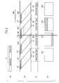
- the CMOS sensors 1s employing the rolling shutter method read pixel data of the captured image line Ln by line Ln.
- the first to the last lines Ln of each screen are temporally shifted.
- the imaging time of each line Ln includes exposure time and read time of pixel data as shown in (a) of Fig. 2 .
- images Im1, Im2, Im3, Im4... displayed on the display unit 7 are as shown in (d) of Fig. 2 .
- the images Im1 and Im4 are normal images which are not influenced by the flash FL and have continuous image brightness.
- the image Im2 is an abnormal image which includes a bright white band in the lower half below the dashed-dotted line and has discontinuous image brightness.
- the hatched area indicates a high-luminance portion.
- the image Im3 is an abnormal image which includes a similar bright white band in the upper half above the dashed-dotted line and has discontinuous image brightness.
- the flash timing is matched to the image capture timing as shown in (b) of Fig. 2 . Accordingly, the above-described phenomenon of discontinuous image brightness does not occur as shown in (d) of Fig. 2 .
- Fig. 3 shows the entire sequence of image taking and recording process by the video camera 101.
- the controller 9 determines in step S1 whether there is an instruction by the operation switch 12 to start shooting. If it is determined that there is an instruction to start shooting (YES), the controller 9 controls and causes the image capture unit 1 to start image capture in accordance with the conditions including the diaphragm and shatter speed.
- the instruction to start shooting may be an instruction by the operation switch 12 to turn on the video camera 101. If it is not determined that there is an instruction to start image capture (NO), the controller 9 returns the process to the step S1 and repeats the step S1.
- step S3 the controller 9 causes the flash detection unit 2 to execute the flash detection process and causes the flash correction unit 8 to execute the flash correction process.
- the controller 9 causes the image signal processing unit 3 to execute the image signal processing in step S4 in parallel to the step S3.
- the flash detection and correction processes of the step S3 are described in detail later.
- step S5 the controller 9 controls and causes the output signal processing unit 6 to display the captured image on the display unit 7.
- step S6 the controller 9 determines whether there is an instruction by the operation switch 12 to start recording. If it is determined that there is an instruction to start recording (YES), the controller 9 causes the recording/reproduction unit 11 to record the encoded data outputted from the compression/decompression processing unit 5 in step S7. If it is not determined that there is an instruction to start recording (NO), the controller 9 moves the process to step S10.
- step S8 the controller 9 determines whether there is an instruction to terminate recording. If it is determined that there is an instruction to terminate recording (YES), in step S9, the controller 9 stops recording in the recording/reproduction unit 11. If it is not determined that there is an instruction to terminate recording (NO), the controller 9 returns the process to the step S7 and repeats the step S7.
- step S10 the controller 9 determines whether there is an instruction by the operation switch 12 to terminate shooting. If it is determined that there is an instruction to terminate shooting (YES), the controller 9 terminates the process. If it is not determined that there is an instruction to terminate shooting (NO), the controller 9 returns the process to step S2 and repeats step S2 and subsequent steps.
- the instruction to terminate image capture may be an instruction by the operation switch 12 to turn off the video camera 101.
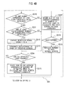
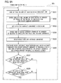
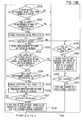
- step S3 The flash detection and correction processes of the step S3 shown in Fig. 3 is described in detail with reference to Figs. 4A and 4B .
- the following steps are executed by the flash detection unit 2 and flash correction unit 8 based on the control by the controller 9.
- the step S3 in the first embodiment is referred to as step S3 1 .
- step S301 the flash detection unit 2 sequentially executes, effective line by effective line, a process of adding up pixel values of effective pixels of each effective line.
- the effective lines refer to lines during a period except the vertical blanking intervals.
- the effective pixels are pixels during a period except the horizontal blanking intervals.
- step S302 the flash detection unit 2 divides the sum of the pixel values obtained in the step S301 by the number of effective pixels to calculate the line average luminance and holds the calculated line average luminance.
- step S303 the flash detection unit 2 executes a process of sequentially adding up the line average luminances.
- step S304 the flash detection unit 2 executes a process of calculating a difference value between each line average luminance calculated in the step S302 and the screen average luminance of the previous screen. The difference calculation process in the step S304 is executed each time that the line average luminance is calculated in step S302.
- the flash detection unit 2 determines whether a line having a difference value of not less than the threshold value is detected.
- the threshold value in this process preferably needs to be changed depending on the situation of the subject but only needs to be set to an optimal value determined by experiments.
- the threshold value is preferably larger enough than the dynamic range of the inputted G signal. The smaller the threshold value is, the higher the sensitivity for flash detection can be.
- the flash detection unit 2 moves the process to the step S306. At this time, the flash detection unit 2 stores detected line information indicating how many lines are included between the detected line and the first line of the frame. If some consecutive lines have difference values of not less than the threshold value, the detected line information may include only the information about the first line of the consecutive lines.
- the flash detection unit 2 deletes the already stored detected line information and moves the process to step S314. If there is no line that has a difference value of not less than the threshold value, it is determined that there is no flash.
- step S306 the flash detection unit 2 determines whether at least a predetermine number of consecutive lines have difference values of not less than the threshold value. If it is not determined that the predetermine number of consecutive lines have difference values of not less than the threshold value (NO), the flash detection unit 2 moves the process to step S307. If it is determined that a predetermine number of consecutive lines have difference values of not less than the threshold value (YES), the flash detection unit 2 moves the process to step S314.
- step S306 can prevent false positives even if the threshold value in step S305 is small.
- the predetermined number used in step S306 may be set to an optimal value determined by experiments. Even if some lines have difference values of not less than the threshold value, it is determined that there is no flash when at least the predetermined number of consecutive lines have difference values of not less than the predetermined value.
- the flash detection unit 2 If it is determined in the step S306 that at least the predetermined number of consecutive lines have difference values of not less than the predetermined value, it is determined that there is a flash.
- the flash detection unit 2 then changes a detection signal "0", which indicates that there is no flash, to a detection signal "1", which indicates that there is a flash.
- the flash detection unit 2 supplies the detection signal of 1 and the stored detected line information to the flash correction unit 8 and then deletes the detected line information.
- step S308 the flash detection unit 2 and flash correction unit 8 determines whether the set mode is the low-delay mode. If it is determined that the set mode is the low-delay mode (YES), the flash correction unit 8 moves the process to step S309. If it is not determined that the set mode is the low-delay mode (NO), the flash correction unit 8 moves the process to step S316.
- step S309 the flash correction unit 8 starts replacement with lines of the previous screen which are indicated by the supplied detected line information.
- step S310 the flash detection unit 2 determines whether a line that has a difference value of less than the threshold value is detected. If it is determined that a line that has a difference value of less than the threshold value is detected (YES), the flash detection unit 2 moves the process to step S311. In this process, the flash detection unit 2 stores the detected line information indicating how many lines are included between the first line of the frame and the detected line. If some consecutive lines have difference values of not less than the threshold value, the detected line information may include only the information about the first line of the consecutive lines.
- the flash detection unit 2 deletes the stored detected line information and moves the process to step S314.
- step S311 the flash detection unit 2 determines whether at least the predetermined number of consecutive lines have difference values of less than the threshold value. If it is not determined that at least the predetermined number of consecutive lines have difference values of less than the threshold value (NO), the flash detection unit 2 moves the process to step S312. If it is determined that at least the predetermined number of consecutive lines have difference values of less than the threshold value (YES), the flash detection unit 2 moves the process to step S314.
- step S311 can prevent false positives even if the threshold value of step S310 is small.
- the threshold value of step S310 is equal to that of step S305.
- the predetermined number used in step S311 may be set to an optimal value determined by experiments.
- the predetermined number used in step S311 may be equal to that used in step S306. Even if a line that has a difference value of less than the threshold value is detected, it is determined that the flash is not yet finished when at least predetermined number of consecutive lines have difference values of less than the threshold value.
- step 312 the flash detection unit 2 changes a detection signal "1" to a detection signal "0" and supplies the detection signal "0" and the stored detected line information to the flash correction unit 8.
- the flash detection unit 2 then deletes the detected line information.
- step S313 the flash correction unit 8 terminates the replacement with lines of the previous screen, which are indicated by the supplied detected line information.
- the flash detection unit 2 then moves the process to step S314.
- step S314 the flash detection unit 2 determines whether the determination is finished for all of the effective lines. If it is determined that the determination is finished for all of the effective lines (YES), the flash detection unit 2 moves the process to step S315. If it is not determined that the determination is finished for all of the effective lines (NO), the flash detection unit 2 returns the process to step S301 and repeats step S301 and subsequent steps.
- step S305 the flash detection unit 2 divides the sum of the line average luminances by the number of effective lines to calculate the screen average luminance.
- the flash detection unit 2 holds the calculated screen average luminance and moves the process to step S5 of Fig. 3 .
- step S308 determines whether the set mode is the low-delay mode (it is determined that the set mode is the screen-based mode). If it is not determined in step S308 that the set mode is the low-delay mode (it is determined that the set mode is the screen-based mode), the flash detection unit 2 determines in step S316 whether the determination for all of the effective lines is finished. If it is not determined that the determination for all of the effective lines is finished (NO), the flash detection unit 2 repeats the process of step S316.
- the flash detection unit 2 divides the sum of the line average luminances by the number of effective lines to calculate the screen average luminance and holds the same.
- step S3108 the flash correction unit 8 determines whether the process proceeds to the next screen.
- the information on whether the process proceeds to the next screen may be supplied to the flash correction unit 8 from the flash detection unit 2 or controller 9. If it is not determined that the process proceeds to the next screen (NO), the flash correction unit 8 repeats the process of step S318. If it is determined that the process proceeds to the next screen (YES), the flash correction unit 8 replaces the current screen in which a flash is detected with a past normal screen and then moves the process to step S5 of Fig. 3 .
- the threshold value used in step S305 is equal to that used in step S310. However, the threshold value used in step S305 may be different from that used in step S310.
- the flash detection unit 2 operates as follows. Based on the lines in which the difference values between the line average luminance and the screen average luminance are not less than a first threshold value, the flash detection unit 2 determines the start line of plural lines of high luminance due to a flash. In Figs. 4A and 4B , the start line is decided when at least the predetermined number of consecutive lines have difference values of not less than the first threshold value.
- the flash detection unit 2 determines the end line of the plural lines of high luminance due to the flash.
- the line just before the first line that has a difference value of less than the second threshold value is decided as the end line.
- the end line is decided when it is determined in step S311 that at least the predetermined number of consecutive lines have difference values of less than the second threshold value.
- Fig. 5A shows an example of the relationship between the vertical position in the screen and the difference value.
- the vertical position of the upper end of the screen is 0 on the horizontal axis. It is assumed that the image data has characteristics shown in Fig. 5A when there is no flash. In the characteristics shown in Fig. 5A , the difference value decreases near the lower end of the screen. If there is a flash at the center of the screen in the vertical direction, the difference value drastically increases.
- the threshold values used in the steps S305 and 310 are a value TH1
- the threshold value used in step S310 is set to a threshold value TH2, which is smaller than the threshold value TH1.
- FIG. 6 shows images Im1, Im2, Im3, Im4... before correction, which are shown in (d) of Fig. 2 .
- the flash correction unit 8 corrects image data in the following manner.
- the flash detection unit 2 detects plural lines of high luminance from middle part of the screen below the dashed-dotted line of the image Im2 at steps S305 and S306 of Fig. 4A .
- the image Im2 has high luminance to the line at the lower end of the screen.
- plural lines of high luminance in a hatched part of the image Im2 are replaced with corresponding plural lines of the image Im1 as shown in (a) of Fig. 6 .
- the flash detection unit 2 detects plural lines of high luminance beginning from the upper end of the screen in the image Im2 at steps S305 and S306 of Fig. 4A .
- the flash detection unit 2 detects plural lines of normal luminance below the dashed-dotted line of the image Im3 at steps S305 and S306 of Fig. 4A .
- the plural lines of high luminance in a hatched part of the image Im3 are replaced with corresponding plural lines of the image Im2 as shown in (a) of Fig. 6 .
- the flash correction unit 8 corrects the images Im2 and Im3 to images Im2' and Im3' as shown in (b) of Fig. 6 , respectively.
- the image data supplied from the flash correction unit 8 to the buffer memory 4 includes the images Im1, Im2' , Im3' , Im4... shown in (b) of Fig. 6 .
- the image Im3 is corrected to the image Im3' using the image Im2 but may be corrected using the image Im1.
- the buffer memory 4 needs to hold image data two screens before the current screen.
- the delay of the image data corresponds to a time of plural lines due to the signal processing at the image signal processing unit 3 and is substantially very little.
- adjustment of various settings of the video camera 101 is performed with the image displayed on the display unit 7 being checked. If the image data includes a large delay, the image cannot be checked at real time, thus making it difficult to perform proper operations in some cases.
- the delay is very little, and the image can be checked at real time, thus enabling proper operations.
- the flash correction unit 8 corrects image data in the following manner.
- the flash correction unit 8 reads image data of the previous screen from the buffer memory 4 and supplies the same through the buffer memory 4 to the compression/decompression processing unit 5 and output signal processing unit 6 irrespective of the need for correction of the image data. Accordingly, as shown in (c) of Fig. 6 , at the times when the images Im1 and Im2 shown in (a) of Fig. 6 before correction are intended to be outputted, the images Im0 and Im1, which are respectively just before the Im1 and Im2, are outputted.
- the flash correction unit 8 outputs the image Im1 instead of the image Im2 having high luminance part and outputs the image Im1 instead of the image Im3 having high luminance part.
- the image data supplied from the flash correction unit 8 to the buffer memory 4 includes the images Im0, Im1, Im1, Im1, Im4 ... shown in (b) of Fig. 6 .
- two consecutive images include high luminance parts, and the buffer memory 4 therefore needs to hold image data three screens before the current screen.
- a video camera 102 as an image processing device of the second embodiment includes a flash detection unit 20 instead of the flash detection unit 2.
- the flash detection unit 20 includes a block average luminance calculation section 201, a block average luminance holding section 202, a line average luminance calculation section 203, a line average luminance holding section 204, a screen average luminance calculation section 205, a screen average luminance holding section 206, a difference calculation section 207, and a flash determination section 208.
- the flash detection unit 20 detects a flash in the following manner under the control by the controller 9.
- the block average luminance calculation section 201 divides the effective pixels of each line in the electric signal supplied from the image capture unit 1 into plural blocks and calculates an average brightness of each block.
- the number of blocks is a power of 2.
- the block average luminance calculation section 201 adds up the values of G signal of the effective pixels in each block and divides the same by the number of effective pixels of the block to calculate the average brightness of the block (block average luminance).
- the block average luminances calculated by the block average luminance calculation unit 201 are inputted to the average luminance holding section 202 and line average luminance calculation section 203.
- the line average luminance calculation section 203 adds up the block average luminances of each line and divides the same by the number of blocks of the line to calculate the average brightness of the line (line average luminance).
- the line average luminances calculated by the line average luminance calculation unit 203 are inputted to the line average luminance holding section 204 and screen average luminance calculation section 205.
- the line average luminance holding section 204 temporarily holds the line average luminances calculated by the line average luminance calculation section 203.
- the screen average luminance calculation section 205 adds up the sequentially inputted line average luminances of the effective lines in each screen and divides the same by the number of effective lines of the screen to calculate the average brightness of the entire screen (screen average luminance).
- the screen average luminance holding section 206 temporarily holds the calculated screen average luminance.
- the difference calculation section 207 receives the block average luminances held by the block average luminance holding section 202, the line average luminances held by the line average luminance holding section 204, and the screen average luminance held by the screen average luminance holding section 206.
- the difference calculation section 207 sequentially calculates the difference between each block average luminance and the screen average luminance (referred to as a block difference value) and the difference between each line average luminance and the screen average luminance (referred to as a line difference value).
- the difference calculation section 207 calculates absolute values of the differences and outputs the same as difference values.
- the difference values calculated by the difference calculation section 207 are inputted to the flash determination section 208.
- the flash determination section 208 determines whether the difference value between each line average luminance and the screen average luminance is less than a set threshold value (a threshold value 1).
- the flash determination section 208 determines whether the difference value between each block average luminance and the screen average luminance is less than a threshold value (a threshold value 2).
- the threshold values 1 and 2 may be different from each other. In the case of setting the threshold values 1 and 2 different from each other, it is preferable that the threshold value 2 is larger than the threshold value 1.
- the flash determination section 208 determines whether at least a predetermined number of consecutive lines have line difference values of not less than the threshold value 1 and have block difference values of not less than the threshold value 2. If it is determined that at least the predetermined number of consecutive lines have line and block difference values of not less than the threshold value 1 and 2, respectively, the flash determination section 208 determines discontinuous image brightness due to a flash.
- the flash determination section 208 outputs: data indicating the number of the first line (as the start time of the flash) that has a line difference value of not less than the threshold value 1 and includes blocks each having a block difference value of not less than the threshold value 2; and data indicating the number of the first line that does not satisfy at least one of the conditions that the line difference value is not less than the threshold value 1 and each block difference value is not less than the threshold value 2.
- the flash determination unit 208 also outputs the detection signal indicating that there is a flash.
- the flash detection and correction processes of the step 3 shown in Fig. 3 correspond to the processes of step S3 2 shown in Figs. 8A and 8B .
- the flash detection and correction processes of the step S3 2 are described in detail with reference to Figs. 8A and 8B .
- step S321 the flash detection unit 20 sequentially executes the process of adding up pixel values of the effective pixels of each block of effective lines effective line by effective line.
- step S322 the flash detection unit 20 divides the sum of the pixel values in each block, which is obtained in the step S321, by the number of effective pixels of the block to calculate the block average luminance thereof and holds the calculated block average luminance.
- step S323 the flash detection unit 20 adds up the block average luminances of each line and in step S324 and divides the sum of the block average luminances by the number of blocks of the line to calculate the line average luminance. The flash detection unit 20 then holds the calculated line average luminance. In step S325, the flash detection unit 20 executes the process of sequentially adding up the line average luminances.
- step S326 the flash detection unit 20 executes the process of calculating the difference between each block average luminance, which is calculated in the step S322, and the screen average luminance of the previous screen (block difference value) and the process of calculating the difference between the line average luminance, which is calculated in the step S324, and the screen average luminance of the previous screen (line difference value).
- the difference calculation process of the step S326 is executed each time the line average luminance is calculated in the step S324.
- step S327 the flash detection unit 20 determines whether a line that has a line difference value of not less than the threshold value (threshold value 1) is detected.
- the flash determination section 208 performs the determination in the steps S327 to S329, S333, and S334.
- the flash detection unit 20 moves the process to step S328. If it is not determined that a line that has a line difference value of not less than the threshold value (threshold value 1) is detected, the flash detection unit 20 moves the process to step S337. If there is no line that has a line difference value of not less than the threshold value, it is determined that there is no flash.
- step S328 the flash detection unit 20 further determines whether the block difference value of each block is less than the threshold value (threshold value 2).
- the flash detection unit 20 moves the process to step S329. At this time, the flash detection unit 20 stores the detected line information about how many lines are included between the detected line and the first line of the frame. If some consecutive lines have line difference values of not less than the threshold value and include blocks each having a block difference value of not less than the threshold value, the detected line information may include information about only the first line of the consecutive lines.
- the flash detection unit 20 deletes the detected line information already stored and moves the process to step S337.
- step S329 the flash detection unit 20 determines whether at least the predetermined number of consecutive lines each satisfy the two conditions, in which the line difference value is not less than the threshold value and the block difference values of the line are not less than the threshold value.
- the state satisfying these two conditions is referred to as a particular state. If it is determined that at least the predetermined number of consecutive lines are in the particular state (YES), the flash detection unit 20 moves the process to step S330. If it is not determined that at least the predetermined number of consecutive lines are in the particular state (NO), the flash detection unit 20 moves the process to step S337.
- the second embodiment it is determined that there is a flash if at least the number of consecutive lines are in the particular state satisfying the aforementioned two conditions. Even if at least the predetermined number of consecutive lines have line difference values of not less than the threshold value, it is determined that there is no flash when one of the conditions that the block difference values of each line are not less than the threshold value is not fulfilled. The reason therefor is described later.
- step S330 the flash detection unit 20 changes the detection signal "0", that indicates that there is no flash, to the detection signal "1", that indicates that there is a flash.
- the flash detection unit 20 supplies the detection signal "1" and the stored detected line information to the flash correction unit 8 and then deletes the detected line information.
- step S331 the flash detection unit 20 and flash correction unit 8 determine whether the set mode is the low-delay mode. If it is determined that the set mode is the low-delay mode (YES), the flash correction unit 8 moves the process to step S332. If it is not determined that the set mode is the low-delay mode (NO), the flash detection unit 20 moves the process to step S339.
- the flash correction unit 8 starts replacement with lines of the previous screen, that are indicated by the supplied detected line information.
- the flash detection unit 20 determines whether a line that has a line difference value of less than the threshold value or includes at least one block having a difference value of less than the threshold value is detected. In other words, the flash detection unit 20 determines in step S333 whether a line not satisfying at least one of the aforementioned two conditions is detected.
- the flash detection unit 20 moves the process to step S334. At this time, the flash detection unit 20 stores the detected line information indicating how many lines are included between the detected line and the first line of the frame. When some consecutive lines do not satisfy the two conditions, the stored detected line information may include information about only the first line.
- the flash detection unit 20 deletes the stored detected line information and moves the process to step S337.
- the flash detection unit 20 determines whether at least the predetermined number of consecutive lines do not satisfy both of the two-conditions. If it is not determined that at least the predetermined number of consecutive lines do not satisfy both of the two-conditions (NO), the flash detection unit 20 moves the process to step S335. If it is determined that at least the predetermined number of consecutive lines do not satisfy both of the two-conditions (YES), the flash detection unit 20 moves the process to step S337.
- step S335 the flash detection unit 20 changes the detection signal "1" to the detection signal "0” and supplies the detection signal "0" and the stored detected line information with the flash correction unit 8. The flash detection unit 20 then deletes the stored detected line information.
- step S336 the flash correction unit 8 terminates the replacement to lines of the previous screen, that are indicated by the supplied detected line. The flash detection unit 20 moves the process to step S337.
- step S337 the flash detection unit 20 determines whether the determination is finished for all of the effective lines. If it is determined that the determination is finished for all of the effective lines (YES), the flash detection unit 20 moves the process to step S338. If it is not determined that the determination is finished for all of the effective lines (NO), the flash detection unit 20 returns the process to step S321 and repeats step S321 and subsequent steps.
- step S3308 the flash detection unit 20 divides the sum of the line average luminances by the number of effective lines of the screen to calculate the screen average luminance and holds the calculated screen average luminance.
- the flash detection unit 20 then moves the process to step S5 of Fig. 3 .
- step S331 determines whether the set mode is the low-delay mode (the set mode is the screen-based mode). If it is not determined in step S331 that the set mode is the low-delay mode (the set mode is the screen-based mode), the flash detection unit 20 performs the same steps S316 to S319, and the description thereof is omitted.
- the threshold value compared with each line difference value in step S333 is smaller than the threshold value compared with each line difference value in step S327.
- the accuracy in detecting that there is a flash is higher than that of the first embodiment.
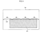
- Fig. 9 shows an example of an image Imi having a screen partially including a high luminance rectangular area Arh. It is assumed that the hatched high luminance area Arh has a white level, for example.
- the high luminance area Arh is not necessarily rectangular.
- the line average luminance is comparatively high.
- the lines other than the effective line Lne in a vertical range of the part where the high luminance area Arh exists have also high line average luminance. Accordingly, in the first embodiment, it can be incorrectly determined that there is a flash in the vertical range of the part in which the high luminance area Arh exists.
- one line is divided into four blocks B1 to B4.
- the block average luminance of the block B1, which is calculated by the block average calculation section 201, is not so high.
- the blocks B2 and B3 have high block average luminance, and the block B4 has a block average luminance lower than that of the blocks B2 and B3.
- Concerning the effective line Lne even if it is determined at step S327 of Fig. 8A that the line difference value of the effective line Lne is not less than the threshold value, it is determined at step S328 that the block difference value of at least the block B1 is less than the threshold value.
- the configuration of an image processing device of the third embodiment is the same as the video camera 101 of the first embodiment shown in Fig. 1 or the video camera 102 of the second embodiment shown in Fig. 7 except the process of correcting image data by the flash correction unit 8.
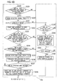
- the process of correcting image data in the third embodiment is described with reference to Figs. 10 to 12 .
- step S3 shown in Fig. 3 corresponds to step S3 3 shown in Figs. 10A and 10B .
- the flash detection and correction processes of the step S3 3 are described in detail with reference to Figs. 10A and 10B .
- the configuration of the image processing device is the same as that of the video camera 101 of Fig. 1 that includes the flash detection unit 2.
- the video camera 102 of Fig. 7 including the flash detection unit 20, that is not particularly shown, is capable of performing the same processes as those of the step S3 3 of Figs. 10A and 10B .
- the same steps as those of Figs. 4A and 4B are given the same reference numerals, and the description thereof is properly omitted.
- step S304 the steps before step S304 are the same as those of Fig. 4A and are not shown in the flowchart.
- Steps S304 to S307 in Fig. 10A are the same as those of Fig. 4A .
- step S307 the flash detection unit 2 changes the detection signal "0", that indicates that there is no flash, to the detection signal "1", that indicates that there is a flash, and supplies the detection signal "1" and the stored detected line information to the flash correction unit 8.
- step S351 the flash detection unit 2 then sets an adjacent area which is located above the flash start line indicated by the supplied detected line information and is adjacent to the flash start line.
- the flash correction unit 8 sets an adjacent area Aadjs composed of plural lines adjacent to a flash start line Lnfs that is the first flash detected line indicated by the supplied detected line information.
- the adjacent area Aadjs includes about five to ten lines, for example.
- step S352 the flash correction unit 8 mixes the lines of the current screen and the lines of the previous screen to generate new lines for the adjacent area Aadjs and replaces the lines of the adjacent area Aadjs with the new lines.
- step S353 the flash correction unit 8 starts replacement with the lines of the previous screen beginning with the flash start line Lnfs.
- step S312 the flash detection unit 2 changes the detection signal "1" to the detection signal "0” and supplies the detection signal "0" and the stored detected line information to the flash correction unit 8.
- step S355 the flash detection unit 8 sets an adjacent area which is located under the flash end line indicated by the supplied detected line information (the line just before the first line after the end of the flash, which is detected at the step S310) and is adjacent to the flash end line.
- the flash correction unit 8 sets an adjacent area Aadj e composed of plural lines which are adjacent to a flash end line Lnfe.
- the adjacent area Aadje also includes about five to ten lines, for example.
- the flash correction unit 8 terminates the replacement with the lines of the previous screen in step S313.
- the flash correction unit 8, then in step S355, mixes the lines of the current screen and the lines of the previous screen in the adjacent area Aadje to generate new lines for the adjacent area Aadje and replaces the lines of the adjacent area Aadje with the new lines.
- the processes of the other steps are the same as described in Figs. 4A and 4B .
- a synthesis weighting factor Wf (i, j) of image data of the current screen and a synthesis weighting factor Wb (i, j) of image data of the previous screen are expressed by Equation (1).
- LS is the position of the first line in the adjacent area Aadjs; LE, the position of the last line in the adjacent area Aadjs; and Lf(i, j), the pixel position of the adjacent area Aadjs.
- the lines of the current screen are mixed with the corresponding lines of the previous screen based on Equation (1) to generate new lines for the adjacent area Aadjs.
- Equation (1) the pixel position is represented by Lf (i, j)
- the image data of the previous screen and the image data of the current screen are mixed line by line, and accordingly, the information of i indicating the horizontal position of an image is not necessary.
- Equation (2) the synthesis weighting factor Wf(i, j) of image data of the current screen and the synthesis weighting factor Wb(i, j) of image data of the previous screen are expressed by Equation (2).
- LS is the position of the first line in the adjacent area Aadje; LE, the position of the last line in the adjacent area Aadje; and Lf(i, j), the pixel position in the adj acent area Aadj e.
- the pixel position is represented by Lf(i, j).
- the image data of the previous screen and the image data of the current screen are mixed line by line, and accordingly, the information of i indicating the horizontal position of an image is not necessary.
- Fig. 12A shows the mixing characteristics by Equation (1).
- the solid line represents a mixed proportion of a current screen line
- the dashed line represents a mixed proportion of a previous screen line.
- the part of the screen from the upper end of the screen to just short of the adjacent area Aadjs is composed of only the lines of the previous screen.
- the proportion of current screen line gradually decreases starting from the first line LS in the adjacent area Aadjs to the last line LE while the proportion of previous screen line gradually increases.
- the part of the screen below the last line LE is composed of only the lines of the previous screen by step S353.
- the flash start line Lnfs may be configured to correspond to the last line LE.
- Fig. 12B shows the mixing characteristics of a current screen line and a previous screen line by Equation (2).
- the solid line represents a proportion of a current screen line
- the dashed line represents a proportion_of a previous screen line.
- the part of the screen from the upper end thereof to just short of the adjacent area Aadje is composed of only the lines of the previous screen.
- the proportion of the current screen line gradually decreases starting from the first line LS in the adjacent area Aadje to the last line LE while the proportion of the previous screen line gradually increases.
- the part of the screen below the last line LE is composed of only the lines of the current screen.
- the flash start line Lnfe may be configured to correspond to the first line LS.
- the current screen line in the case where lower part of the screen has high luminance like the image Im2 of Fig. 2 , in the adjacent area Aadjs which is located above the flash start line Lnfs and is not influenced by the flash, the current screen line gradually changes to the previous screen line from the first line LS to the last line LE. This can reduce unnatural looking due to mixing of the image data of the current screen and the image data of the previous screen.
- Equation (3) Mf(i, j) is brightness of a pixel
- ThH and ThL are threshold values for brightness, that satisfy ThH>ThL.
- the brightness of each effective pixel detected by the flash detection unit 2 or 20 may be inputted to the flash correction unit 8.
- Equation (3) in the adjacent areas Aadjs and Aadje, if the brightness Mf(i, j) of each pixel is smaller than the small threshold value ThL, the synthesis weighting factor Wf(i, j) for the image data of the current screen is 1, and the synthesis weighting factor Wb(i, j) for the image data of the current screen is 0.
- the pixel is likely to be not influenced by a flash. Accordingly, only the image data of the current screen is used for the pixel.
- the synthesis weighting factor Wf(i, j) for the image data of the current screen is 0, and the synthesis weighting factor Wb(i, j) for the image data of the current screen is 1.
- the pixel is likely to be influenced by a flash. Accordingly, only the image data of the previous screen is used for the pixel.
- the pixel data of the current screen and the pixel data of the previous screen are adaptively mixed according to the characteristics of Equation (3).
- the configuration of an image processing device of a fourth embodiment is the same as that of the video camera 102 of the second embodiment shown in Fig. 7 and differs from the second embodiment in the process of detecting a flash by the flash detection unit 20.
- the process of detecting a flash in the fourth embodiment is described with reference to Figs. 13A and 13B and Fig. 14 .
- the flash detection and correction processes of the step S3 shown in Fig. 3 corresponds to step S3 4 shown in Figs. 13A and 13B .
- the flash detection and correction processes of the step S3 4 are described in detail with reference to Figs. 13A and 13B .
- Figs. 13A and 13B the same steps as those in Figs. 8A and 8B are given the same reference numerals, and the description thereof is properly omitted.
- step S327 the flash detection unit 20 determines whether a line that has a line difference value of not less than the threshold value (threshold value 1) is detected. If it is determined that a line that has a line difference value of not less than the threshold value (YES) is detected, the flash detection unit 20 moves the process to step S361. If it is not determined that a line that has a line difference value of not less than the threshold value is detected (NO), the flash detection unit 20 moves the process to step S337.
- threshold value 1 the threshold value 1
- step S361 the flash detection unit 20 determines whether all of the blocks of the previous line have block average luminances of not less than a threshold value.
- the threshold value used in step S361 may be equal to the threshold value 2 used in step S328 or may be a little different from the same.
- the threshold value used in step S361 is set equal to the threshold value 2.
- the flash detection unit 20 moves the process to step S328. If any one of the blocks of the previous line has a block difference value of not less than the threshold value (threshold value 2) (NO), the flash detection unit 20 moves the process to step S337.
- step S328 the flash detection unit 20 determines whether at least the predetermined number of consecutive lines are in the particular state, that satisfies the two conditions where the line difference value is not less than the threshold value and each block difference values is not less than the threshold value.
- step S361 only when it is determined in step S361 that all of the blocks in the previous line have block difference values of less than the threshold value, it is determined that the current line is in the particular state, and the process of the step S329 is executed.
- Fig. 14 shows an example of an image Imi1 that includes the screen partially having a high luminance trapezoidal area Arh1, for example.
- the high luminance trapezoidal area Arh1 which is hatched in the drawing, has a white level, for example.
- the high luminance area Arh1 is not necessarily trapezoidal.
- the upper end of the high luminance area may vary depending on the position in the horizontal direction.
- it is assumed that the image one frame before the image Imi1 is a normal image not including the high luminance area Arh1.
- an effective line Lne0 just before the effective line Lne1 in the high luminance area Arh1 is located as shown in the drawing.
- the block difference value of the block B1 is comparatively small, but the block difference values of the blocks B2 to B4 are comparatively large. Accordingly, when the effective line Lne1 is the current line, all the blocks on the previous line do not have block difference values of less than the threshold value.
- step S361 the flash detection unit 20 does not falsely detect that the high luminance area Arh1 is a high luminance area due to a flash.
- step S361 the flash detection unit 20 does not falsely detect that the high luminance area Arh1 is a high luminance area due to a flash.
- the difference calculation section 207 only needs to hold the block difference values of the blocks of the previous line.
- the fourth embodiment it is determined whether the block difference values of the line just before the current line are less than the threshold value. However, it may be determined whether the block difference values of the line two or three lines before the current line are less than the threshold value. In other words, it should be determined whether the block difference values in a line which is located above and near the current line are less than the threshold value.
- the order of the steps S327, S361, and S328 is not limited to the order shown in Figs. 13A and 13B and may be properly changed.
- the threshold value compared with the line difference value in the step S333 is preferably smaller than the threshold value compared with the line difference value in step S327.
- the configurations of the fourth and third embodiments are combined.
- the configuration of the image processing device of a fifth embodiment is the same as that of the video camera 102 of the second embodiment shown in Fig. 7 and differs from that of the second embodiment in the process of detecting a flash by the flash detection unit 20.
- the process of detecting a flash of the fifth embodiment is described with reference to Figs. 15A and 15B .
- step S3 shown in Fig. 3 corresponds to step S3 5 shown in Figs. 15A and 15B .
- the flash detection and correction processes of step S3 5 is described in detail with reference to Figs. 15A and 15B .
- Figs. 15A and 15B the same steps as those of Figs. 8A and 8B are given the same reference numerals, and the description thereof is properly omitted.
- step S327 the flash detection unit 20 determines whether a line having a line difference value of not less than the threshold value (threshold value 1) is detected. If it is determined that a line that has a line difference value of not less than the threshold value is detected (YES), the flash detection unit 20 moves the process to step S371. If it is not determined that a line that has a line difference value of not less than the threshold value is detected (NO), the flash detection unit 20 moves the process to step S337.
- threshold value 1 the threshold value 1
- step S371 the flash detection unit 20 determines whether, in the same screen as the current line, the difference value between each block average luminance of the current line and the corresponding block average luminance of the previous line is not less than a predetermined threshold value.
- the flash detection unit 20 compares the block average luminances of blocks at the same horizontal position in the current and previous lines.
- the threshold value used in step S371 (threshold value 3) is unnecessarily equal to the threshold value 2 used in the step S328 and may be set to a proper value.
- the flash detection unit 20 moves the process to step S328. If the difference value between any one block average luminance of the current line and the corresponding block average luminance of the previous line is less than the predetermined threshold value (NO), the flash detection unit 20 moves the process to step S337.
- step S328 and subsequent steps are the same as that of Figs. 8A and 8B .
- the current line is determined to be a line in the particular state, and the process of step S329 is executed.
- Fig. 14 it is assumed that the effective line Lne1 is the current line, and in the fifth embodiment, the block average luminances of blocks B1 to B4 in the effective line Lne1 are compared with those of blocks B1 to B4 in the previous effective line Lne0, respectively.
- the difference value of the block average luminance between the blocks B1 of the current and previous effective lines Lne1 and Lne0 is not less than the threshold value, but the difference values of the blocks B2 to B4 are less than the threshold value.
- the current line is the effective line Lne0 or a line above the effective line Lne0, similarly, it is not determined that the differences of all the blocks are equal to or more than the threshold value.
- step S371 the flash detection unit 20 cannot falsely detect that the high luminance area Arh1 is a high luminance area due to a flash.
- the flash detection unit 20 cannot falsely detect that the high luminance area Arh1 is a high luminance area due to a flash.
- the difference calculation section 207 only needs to hold the block average luminances of the blocks of the previous line and calculate the difference values in block average luminance between the blocks of the previous line and the corresponding blocks of the current line.
- the possibility of false positives in detecting a flash can be further reduced compared with the second embodiment.
- the difference value between each block average luminance of the current line and the corresponding block average luminance of the previous line is less than a threshold value.
- the threshold value compared with the line difference value in the step S333 is preferably smaller than the threshold value compared with the line difference value in the step S327.
- the above-described configurations of the fifth and third embodiments are combined.
- the configurations of the fourth and fifth embodiments can be combined.
- the present invention is not limited to the above-described embodiments and can be variously changed without departing from the scope of the invention.
- Each embodiment is described with a video camera as an example.
- the image processing device, method, and program of the present invention are applicable to arbitrary electronic devices which handle image data.
- the image processing device of each embodiment may be mounted on an image display device, an information processing apparatus such as a computer to correct image data including a screen partially having high luminance inside the image display device or information processing device.
- the buffer memory 4 is used which is separately provided from the image signal processing unit 3 and the compression/decompression processing unit 5.
- the buffer memory 4 may be a buffer memory used in the image signal processing unit 3 or compression/decompression processing unit 5, and the circuit (block) configuration can be properly changed.
- the image processing program of the present invention may be recorded in a computer-readable recording medium to be provided or may be delivered through a communication line such as the Internet.
- the image processing program recorded in the recording medium or the image processing program delivered through a communication may be stored in the image processing device and caused to execute the aforementioned image processing method.
Landscapes
- Engineering & Computer Science (AREA)
- Multimedia (AREA)
- Signal Processing (AREA)
- Studio Devices (AREA)
- Facsimile Image Signal Circuits (AREA)
- Picture Signal Circuits (AREA)
Applications Claiming Priority (4)
| Application Number | Priority Date | Filing Date | Title |
|---|---|---|---|
| JP2012029323 | 2012-02-14 | ||
| JP2012029318 | 2012-02-14 | ||
| JP2012229508A JP5928290B2 (ja) | 2012-02-14 | 2012-10-17 | 画像処理装置、画像処理方法、画像処理プログラム |
| JP2012229507A JP2013192200A (ja) | 2012-02-14 | 2012-10-17 | 画像処理装置、画像処理方法、画像処理プログラム |
Publications (3)
| Publication Number | Publication Date |
|---|---|
| EP2629508A2 true EP2629508A2 (de) | 2013-08-21 |
| EP2629508A3 EP2629508A3 (de) | 2017-11-01 |
| EP2629508B1 EP2629508B1 (de) | 2019-03-27 |
Family
ID=47900402
Family Applications (1)
| Application Number | Title | Priority Date | Filing Date |
|---|---|---|---|
| EP13000704.0A Active EP2629508B1 (de) | 2012-02-14 | 2013-02-11 | Bildverarbeitungsvorrichtung, -verfahren und -programm zur Biltzlichterkennung |
Country Status (2)
| Country | Link |
|---|---|
| US (1) | US8947588B2 (de) |
| EP (1) | EP2629508B1 (de) |
Families Citing this family (4)
| Publication number | Priority date | Publication date | Assignee | Title |
|---|---|---|---|---|
| JP6145746B2 (ja) * | 2013-03-08 | 2017-06-14 | パナソニックIpマネジメント株式会社 | 撮像装置 |
| CN105635611A (zh) * | 2014-11-03 | 2016-06-01 | 中兴通讯股份有限公司 | 投影仪自适应调整方法及装置 |
| JP6808365B2 (ja) * | 2016-06-15 | 2021-01-06 | キヤノン株式会社 | 撮像装置、その制御方法、及びプログラム |
| US10458924B2 (en) * | 2016-07-04 | 2019-10-29 | Hitachi High-Technologies Corporation | Inspection apparatus and inspection method |
Citations (3)
| Publication number | Priority date | Publication date | Assignee | Title |
|---|---|---|---|---|
| JP2010213220A (ja) | 2009-03-12 | 2010-09-24 | Fujifilm Corp | 撮像装置及び撮像制御方法 |
| JP2011015222A (ja) | 2009-07-02 | 2011-01-20 | Fujifilm Corp | 撮像装置及び撮像制御方法 |
| JP2011101208A (ja) | 2009-11-06 | 2011-05-19 | Panasonic Corp | 撮像装置 |
Family Cites Families (3)
| Publication number | Priority date | Publication date | Assignee | Title |
|---|---|---|---|---|
| JP5144481B2 (ja) * | 2008-12-02 | 2013-02-13 | 富士フイルム株式会社 | 撮像装置及び撮像方法 |
| JP5410510B2 (ja) * | 2009-04-16 | 2014-02-05 | パナソニック株式会社 | 撮像装置、外部閃光検出方法、プログラムおよび集積回路 |
| JP2012156634A (ja) * | 2011-01-24 | 2012-08-16 | Sony Corp | フラッシュバンド処理回路、フラッシュバンド処理方法、撮像装置及び撮像処理方法 |
-
2013
- 2013-01-24 US US13/749,184 patent/US8947588B2/en active Active
- 2013-02-11 EP EP13000704.0A patent/EP2629508B1/de active Active
Patent Citations (3)
| Publication number | Priority date | Publication date | Assignee | Title |
|---|---|---|---|---|
| JP2010213220A (ja) | 2009-03-12 | 2010-09-24 | Fujifilm Corp | 撮像装置及び撮像制御方法 |
| JP2011015222A (ja) | 2009-07-02 | 2011-01-20 | Fujifilm Corp | 撮像装置及び撮像制御方法 |
| JP2011101208A (ja) | 2009-11-06 | 2011-05-19 | Panasonic Corp | 撮像装置 |
Also Published As
| Publication number | Publication date |
|---|---|
| EP2629508A3 (de) | 2017-11-01 |
| US8947588B2 (en) | 2015-02-03 |
| EP2629508B1 (de) | 2019-03-27 |
| US20130208144A1 (en) | 2013-08-15 |
Similar Documents
| Publication | Publication Date | Title |
|---|---|---|
| JP5089405B2 (ja) | 画像処理装置及び画像処理方法並びに撮像装置 | |
| US8599283B2 (en) | Image capture apparatus and image capturing method | |
| US9215379B2 (en) | Imaging apparatus and imaging processing method for detecting and correcting flash band | |
| US8373769B2 (en) | Imaging apparatus, imaging processing method and recording medium | |
| US20150036878A1 (en) | Image processing apparatus and image processing method | |
| CN101964874A (zh) | 图像处理装置及图像处理方法 | |
| US20170019579A1 (en) | Image processing apparatus and image processing method | |
| JP2015149691A (ja) | 画像補正装置、画像補正方法、及び、撮像装置 | |
| EP2629508B1 (de) | Bildverarbeitungsvorrichtung, -verfahren und -programm zur Biltzlichterkennung | |
| JP2011166753A (ja) | 撮像装置 | |
| US8964109B2 (en) | Image processing device and method | |
| JP2013192200A (ja) | 画像処理装置、画像処理方法、画像処理プログラム | |
| JP4444218B2 (ja) | 動画用明るさ補正装置ならびにその制御方法およびその制御プログラム | |
| JP5569361B2 (ja) | 撮像装置およびホワイトバランス制御方法 | |
| US8339473B2 (en) | Video camera with flicker prevention | |
| US20110085731A1 (en) | Digital image processing apparatus for recognizing fireworks, method of operating the same, and computer-readable storage medium | |
| JP5900278B2 (ja) | 画像処理装置及び方法 | |
| US11405562B2 (en) | Image processing apparatus, method of controlling the same, image capturing apparatus, and storage medium | |
| US10469761B2 (en) | Image capturing apparatus | |
| JP6250970B2 (ja) | 画像処理装置、撮像装置、画像処理方法、プログラム、及び記録媒体 | |
| JP5928290B2 (ja) | 画像処理装置、画像処理方法、画像処理プログラム | |
| JP2006287814A (ja) | 撮像装置及び動きベクトル決定方法 | |
| JP2005333251A (ja) | 撮像装置、カメラ及び撮像処理方法 | |
| JP5757472B2 (ja) | 画像処理装置、画像処理方法、画像処理プログラム | |
| JP5264695B2 (ja) | 画像処理方法、画像処理装置、及び撮像装置 |
Legal Events
| Date | Code | Title | Description |
|---|---|---|---|
| PUAI | Public reference made under article 153(3) epc to a published international application that has entered the european phase |
Free format text: ORIGINAL CODE: 0009012 |
|
| AK | Designated contracting states |
Kind code of ref document: A2 Designated state(s): AL AT BE BG CH CY CZ DE DK EE ES FI FR GB GR HR HU IE IS IT LI LT LU LV MC MK MT NL NO PL PT RO RS SE SI SK SM TR |
|
| AX | Request for extension of the european patent |
Extension state: BA ME |
|
| PUAL | Search report despatched |
Free format text: ORIGINAL CODE: 0009013 |
|
| AK | Designated contracting states |
Kind code of ref document: A3 Designated state(s): AL AT BE BG CH CY CZ DE DK EE ES FI FR GB GR HR HU IE IS IT LI LT LU LV MC MK MT NL NO PL PT RO RS SE SI SK SM TR |
|
| AX | Request for extension of the european patent |
Extension state: BA ME |
|
| RIC1 | Information provided on ipc code assigned before grant |
Ipc: H04N 5/353 20110101ALI20170927BHEP Ipc: H04N 5/235 20060101AFI20170927BHEP Ipc: H04N 5/217 20110101ALN20170927BHEP |
|
| 17P | Request for examination filed |
Effective date: 20180427 |
|
| RBV | Designated contracting states (corrected) |
Designated state(s): AL AT BE BG CH CY CZ DE DK EE ES FI FR GB GR HR HU IE IS IT LI LT LU LV MC MK MT NL NO PL PT RO RS SE SI SK SM TR |
|
| GRAP | Despatch of communication of intention to grant a patent |
Free format text: ORIGINAL CODE: EPIDOSNIGR1 |
|
| STAA | Information on the status of an ep patent application or granted ep patent |
Free format text: STATUS: GRANT OF PATENT IS INTENDED |
|
| RIC1 | Information provided on ipc code assigned before grant |
Ipc: H04N 5/353 20110101ALI20180906BHEP Ipc: H04N 5/217 20110101ALN20180906BHEP Ipc: H04N 5/235 20060101AFI20180906BHEP |
|
| RIC1 | Information provided on ipc code assigned before grant |
Ipc: H04N 5/353 20110101ALI20180913BHEP Ipc: H04N 5/235 20060101AFI20180913BHEP Ipc: H04N 5/217 20110101ALN20180913BHEP |
|
| INTG | Intention to grant announced |
Effective date: 20181004 |
|
| GRAS | Grant fee paid |
Free format text: ORIGINAL CODE: EPIDOSNIGR3 |
|
| GRAA | (expected) grant |
Free format text: ORIGINAL CODE: 0009210 |
|
| STAA | Information on the status of an ep patent application or granted ep patent |
Free format text: STATUS: THE PATENT HAS BEEN GRANTED |
|
| AK | Designated contracting states |
Kind code of ref document: B1 Designated state(s): AL AT BE BG CH CY CZ DE DK EE ES FI FR GB GR HR HU IE IS IT LI LT LU LV MC MK MT NL NO PL PT RO RS SE SI SK SM TR |
|
| REG | Reference to a national code |
Ref country code: GB Ref legal event code: FG4D |
|
| REG | Reference to a national code |
Ref country code: CH Ref legal event code: EP |
|
| REG | Reference to a national code |
Ref country code: AT Ref legal event code: REF Ref document number: 1114401 Country of ref document: AT Kind code of ref document: T Effective date: 20190415 |
|
| REG | Reference to a national code |
Ref country code: IE Ref legal event code: FG4D |
|
| REG | Reference to a national code |
Ref country code: DE Ref legal event code: R096 Ref document number: 602013052803 Country of ref document: DE |
|
| PG25 | Lapsed in a contracting state [announced via postgrant information from national office to epo] |
Ref country code: LT Free format text: LAPSE BECAUSE OF FAILURE TO SUBMIT A TRANSLATION OF THE DESCRIPTION OR TO PAY THE FEE WITHIN THE PRESCRIBED TIME-LIMIT Effective date: 20190327 Ref country code: NO Free format text: LAPSE BECAUSE OF FAILURE TO SUBMIT A TRANSLATION OF THE DESCRIPTION OR TO PAY THE FEE WITHIN THE PRESCRIBED TIME-LIMIT Effective date: 20190627 Ref country code: FI Free format text: LAPSE BECAUSE OF FAILURE TO SUBMIT A TRANSLATION OF THE DESCRIPTION OR TO PAY THE FEE WITHIN THE PRESCRIBED TIME-LIMIT Effective date: 20190327 Ref country code: SE Free format text: LAPSE BECAUSE OF FAILURE TO SUBMIT A TRANSLATION OF THE DESCRIPTION OR TO PAY THE FEE WITHIN THE PRESCRIBED TIME-LIMIT Effective date: 20190327 |
|
| REG | Reference to a national code |
Ref country code: NL Ref legal event code: MP Effective date: 20190327 |
|
| PG25 | Lapsed in a contracting state [announced via postgrant information from national office to epo] |
Ref country code: BG Free format text: LAPSE BECAUSE OF FAILURE TO SUBMIT A TRANSLATION OF THE DESCRIPTION OR TO PAY THE FEE WITHIN THE PRESCRIBED TIME-LIMIT Effective date: 20190627 Ref country code: GR Free format text: LAPSE BECAUSE OF FAILURE TO SUBMIT A TRANSLATION OF THE DESCRIPTION OR TO PAY THE FEE WITHIN THE PRESCRIBED TIME-LIMIT Effective date: 20190628 Ref country code: LV Free format text: LAPSE BECAUSE OF FAILURE TO SUBMIT A TRANSLATION OF THE DESCRIPTION OR TO PAY THE FEE WITHIN THE PRESCRIBED TIME-LIMIT Effective date: 20190327 Ref country code: HR Free format text: LAPSE BECAUSE OF FAILURE TO SUBMIT A TRANSLATION OF THE DESCRIPTION OR TO PAY THE FEE WITHIN THE PRESCRIBED TIME-LIMIT Effective date: 20190327 Ref country code: RS Free format text: LAPSE BECAUSE OF FAILURE TO SUBMIT A TRANSLATION OF THE DESCRIPTION OR TO PAY THE FEE WITHIN THE PRESCRIBED TIME-LIMIT Effective date: 20190327 Ref country code: NL Free format text: LAPSE BECAUSE OF FAILURE TO SUBMIT A TRANSLATION OF THE DESCRIPTION OR TO PAY THE FEE WITHIN THE PRESCRIBED TIME-LIMIT Effective date: 20190327 |
|
| REG | Reference to a national code |
Ref country code: AT Ref legal event code: MK05 Ref document number: 1114401 Country of ref document: AT Kind code of ref document: T Effective date: 20190327 |
|
| PG25 | Lapsed in a contracting state [announced via postgrant information from national office to epo] |
Ref country code: PT Free format text: LAPSE BECAUSE OF FAILURE TO SUBMIT A TRANSLATION OF THE DESCRIPTION OR TO PAY THE FEE WITHIN THE PRESCRIBED TIME-LIMIT Effective date: 20190727 Ref country code: CZ Free format text: LAPSE BECAUSE OF FAILURE TO SUBMIT A TRANSLATION OF THE DESCRIPTION OR TO PAY THE FEE WITHIN THE PRESCRIBED TIME-LIMIT Effective date: 20190327 Ref country code: AL Free format text: LAPSE BECAUSE OF FAILURE TO SUBMIT A TRANSLATION OF THE DESCRIPTION OR TO PAY THE FEE WITHIN THE PRESCRIBED TIME-LIMIT Effective date: 20190327 Ref country code: RO Free format text: LAPSE BECAUSE OF FAILURE TO SUBMIT A TRANSLATION OF THE DESCRIPTION OR TO PAY THE FEE WITHIN THE PRESCRIBED TIME-LIMIT Effective date: 20190327 Ref country code: ES Free format text: LAPSE BECAUSE OF FAILURE TO SUBMIT A TRANSLATION OF THE DESCRIPTION OR TO PAY THE FEE WITHIN THE PRESCRIBED TIME-LIMIT Effective date: 20190327 Ref country code: EE Free format text: LAPSE BECAUSE OF FAILURE TO SUBMIT A TRANSLATION OF THE DESCRIPTION OR TO PAY THE FEE WITHIN THE PRESCRIBED TIME-LIMIT Effective date: 20190327 Ref country code: SK Free format text: LAPSE BECAUSE OF FAILURE TO SUBMIT A TRANSLATION OF THE DESCRIPTION OR TO PAY THE FEE WITHIN THE PRESCRIBED TIME-LIMIT Effective date: 20190327 Ref country code: IT Free format text: LAPSE BECAUSE OF FAILURE TO SUBMIT A TRANSLATION OF THE DESCRIPTION OR TO PAY THE FEE WITHIN THE PRESCRIBED TIME-LIMIT Effective date: 20190327 |
|
| PG25 | Lapsed in a contracting state [announced via postgrant information from national office to epo] |
Ref country code: PL Free format text: LAPSE BECAUSE OF FAILURE TO SUBMIT A TRANSLATION OF THE DESCRIPTION OR TO PAY THE FEE WITHIN THE PRESCRIBED TIME-LIMIT Effective date: 20190327 Ref country code: SM Free format text: LAPSE BECAUSE OF FAILURE TO SUBMIT A TRANSLATION OF THE DESCRIPTION OR TO PAY THE FEE WITHIN THE PRESCRIBED TIME-LIMIT Effective date: 20190327 |
|
| PG25 | Lapsed in a contracting state [announced via postgrant information from national office to epo] |
Ref country code: IS Free format text: LAPSE BECAUSE OF FAILURE TO SUBMIT A TRANSLATION OF THE DESCRIPTION OR TO PAY THE FEE WITHIN THE PRESCRIBED TIME-LIMIT Effective date: 20190727 Ref country code: AT Free format text: LAPSE BECAUSE OF FAILURE TO SUBMIT A TRANSLATION OF THE DESCRIPTION OR TO PAY THE FEE WITHIN THE PRESCRIBED TIME-LIMIT Effective date: 20190327 |
|
| REG | Reference to a national code |
Ref country code: DE Ref legal event code: R097 Ref document number: 602013052803 Country of ref document: DE |
|
| PG25 | Lapsed in a contracting state [announced via postgrant information from national office to epo] |
Ref country code: DK Free format text: LAPSE BECAUSE OF FAILURE TO SUBMIT A TRANSLATION OF THE DESCRIPTION OR TO PAY THE FEE WITHIN THE PRESCRIBED TIME-LIMIT Effective date: 20190327 |
|
| PLBE | No opposition filed within time limit |
Free format text: ORIGINAL CODE: 0009261 |
|
| STAA | Information on the status of an ep patent application or granted ep patent |
Free format text: STATUS: NO OPPOSITION FILED WITHIN TIME LIMIT |
|
| PG25 | Lapsed in a contracting state [announced via postgrant information from national office to epo] |
Ref country code: SI Free format text: LAPSE BECAUSE OF FAILURE TO SUBMIT A TRANSLATION OF THE DESCRIPTION OR TO PAY THE FEE WITHIN THE PRESCRIBED TIME-LIMIT Effective date: 20190327 |
|
| 26N | No opposition filed |
Effective date: 20200103 |
|
| PG25 | Lapsed in a contracting state [announced via postgrant information from national office to epo] |
Ref country code: TR Free format text: LAPSE BECAUSE OF FAILURE TO SUBMIT A TRANSLATION OF THE DESCRIPTION OR TO PAY THE FEE WITHIN THE PRESCRIBED TIME-LIMIT Effective date: 20190327 |
|
| REG | Reference to a national code |
Ref country code: CH Ref legal event code: PL |
|
| REG | Reference to a national code |
Ref country code: BE Ref legal event code: MM Effective date: 20200229 |
|
| PG25 | Lapsed in a contracting state [announced via postgrant information from national office to epo] |
Ref country code: MC Free format text: LAPSE BECAUSE OF FAILURE TO SUBMIT A TRANSLATION OF THE DESCRIPTION OR TO PAY THE FEE WITHIN THE PRESCRIBED TIME-LIMIT Effective date: 20190327 Ref country code: LU Free format text: LAPSE BECAUSE OF NON-PAYMENT OF DUE FEES Effective date: 20200211 |
|
| PG25 | Lapsed in a contracting state [announced via postgrant information from national office to epo] |
Ref country code: CH Free format text: LAPSE BECAUSE OF NON-PAYMENT OF DUE FEES Effective date: 20200229 Ref country code: LI Free format text: LAPSE BECAUSE OF NON-PAYMENT OF DUE FEES Effective date: 20200229 |
|
| PG25 | Lapsed in a contracting state [announced via postgrant information from national office to epo] |
Ref country code: IE Free format text: LAPSE BECAUSE OF NON-PAYMENT OF DUE FEES Effective date: 20200211 Ref country code: FR Free format text: LAPSE BECAUSE OF NON-PAYMENT OF DUE FEES Effective date: 20200229 |
|
| PG25 | Lapsed in a contracting state [announced via postgrant information from national office to epo] |
Ref country code: BE Free format text: LAPSE BECAUSE OF NON-PAYMENT OF DUE FEES Effective date: 20200229 |
|
| PG25 | Lapsed in a contracting state [announced via postgrant information from national office to epo] |
Ref country code: MT Free format text: LAPSE BECAUSE OF FAILURE TO SUBMIT A TRANSLATION OF THE DESCRIPTION OR TO PAY THE FEE WITHIN THE PRESCRIBED TIME-LIMIT Effective date: 20190327 Ref country code: CY Free format text: LAPSE BECAUSE OF FAILURE TO SUBMIT A TRANSLATION OF THE DESCRIPTION OR TO PAY THE FEE WITHIN THE PRESCRIBED TIME-LIMIT Effective date: 20190327 |
|
| PG25 | Lapsed in a contracting state [announced via postgrant information from national office to epo] |
Ref country code: MK Free format text: LAPSE BECAUSE OF FAILURE TO SUBMIT A TRANSLATION OF THE DESCRIPTION OR TO PAY THE FEE WITHIN THE PRESCRIBED TIME-LIMIT Effective date: 20190327 |
|
| REG | Reference to a national code |
Ref country code: DE Ref legal event code: R079 Ref document number: 602013052803 Country of ref document: DE Free format text: PREVIOUS MAIN CLASS: H04N0005235000 Ipc: H04N0023700000 |
|
| PGFP | Annual fee paid to national office [announced via postgrant information from national office to epo] |
Ref country code: GB Payment date: 20241227 Year of fee payment: 13 |
|
| PGFP | Annual fee paid to national office [announced via postgrant information from national office to epo] |
Ref country code: DE Payment date: 20241231 Year of fee payment: 13 |