EP2629445B1 - Method for transmitting control information and apparatus for same - Google Patents
Method for transmitting control information and apparatus for same Download PDFInfo
- Publication number
- EP2629445B1 EP2629445B1 EP11832727.9A EP11832727A EP2629445B1 EP 2629445 B1 EP2629445 B1 EP 2629445B1 EP 11832727 A EP11832727 A EP 11832727A EP 2629445 B1 EP2629445 B1 EP 2629445B1
- Authority
- EP
- European Patent Office
- Prior art keywords
- nack
- ack
- dtx
- pucch
- harq
- Prior art date
- Legal status (The legal status is an assumption and is not a legal conclusion. Google has not performed a legal analysis and makes no representation as to the accuracy of the status listed.)
- Active
Links
- 238000000034 method Methods 0.000 title claims description 19
- 230000005540 biological transmission Effects 0.000 claims description 62
- 238000013507 mapping Methods 0.000 claims description 34
- 230000004044 response Effects 0.000 claims description 25
- 238000004891 communication Methods 0.000 claims description 21
- 101000741965 Homo sapiens Inactive tyrosine-protein kinase PRAG1 Proteins 0.000 claims 84
- 102100038659 Inactive tyrosine-protein kinase PRAG1 Human genes 0.000 claims 84
- 230000002776 aggregation Effects 0.000 description 6
- 238000004220 aggregation Methods 0.000 description 6
- 238000005516 engineering process Methods 0.000 description 6
- 238000013468 resource allocation Methods 0.000 description 5
- 230000011664 signaling Effects 0.000 description 5
- 239000013256 coordination polymer Substances 0.000 description 4
- 230000008878 coupling Effects 0.000 description 4
- 238000010168 coupling process Methods 0.000 description 4
- 238000005859 coupling reaction Methods 0.000 description 4
- 125000004122 cyclic group Chemical group 0.000 description 4
- 230000007480 spreading Effects 0.000 description 4
- 239000000969 carrier Substances 0.000 description 3
- 230000008054 signal transmission Effects 0.000 description 3
- 230000004913 activation Effects 0.000 description 2
- 238000010276 construction Methods 0.000 description 2
- 230000000694 effects Effects 0.000 description 2
- 238000003491 array Methods 0.000 description 1
- 238000001514 detection method Methods 0.000 description 1
- 230000006866 deterioration Effects 0.000 description 1
- 230000006870 function Effects 0.000 description 1
- 230000007774 longterm Effects 0.000 description 1
- 239000011159 matrix material Substances 0.000 description 1
- 238000010295 mobile communication Methods 0.000 description 1
- 238000012544 monitoring process Methods 0.000 description 1
- 230000008569 process Effects 0.000 description 1
- 238000012545 processing Methods 0.000 description 1
- 238000004549 pulsed laser deposition Methods 0.000 description 1
Images


Classifications
-
- H—ELECTRICITY
- H04—ELECTRIC COMMUNICATION TECHNIQUE
- H04W—WIRELESS COMMUNICATION NETWORKS
- H04W72/00—Local resource management
- H04W72/20—Control channels or signalling for resource management
- H04W72/21—Control channels or signalling for resource management in the uplink direction of a wireless link, i.e. towards the network
-
- H—ELECTRICITY
- H04—ELECTRIC COMMUNICATION TECHNIQUE
- H04L—TRANSMISSION OF DIGITAL INFORMATION, e.g. TELEGRAPHIC COMMUNICATION
- H04L1/00—Arrangements for detecting or preventing errors in the information received
- H04L1/12—Arrangements for detecting or preventing errors in the information received by using return channel
- H04L1/16—Arrangements for detecting or preventing errors in the information received by using return channel in which the return channel carries supervisory signals, e.g. repetition request signals
- H04L1/18—Automatic repetition systems, e.g. Van Duuren systems
- H04L1/1829—Arrangements specially adapted for the receiver end
- H04L1/1835—Buffer management
- H04L1/1845—Combining techniques, e.g. code combining
-
- H—ELECTRICITY
- H04—ELECTRIC COMMUNICATION TECHNIQUE
- H04L—TRANSMISSION OF DIGITAL INFORMATION, e.g. TELEGRAPHIC COMMUNICATION
- H04L1/00—Arrangements for detecting or preventing errors in the information received
- H04L1/0001—Systems modifying transmission characteristics according to link quality, e.g. power backoff
- H04L1/0023—Systems modifying transmission characteristics according to link quality, e.g. power backoff characterised by the signalling
- H04L1/0028—Formatting
- H04L1/0029—Reduction of the amount of signalling, e.g. retention of useful signalling or differential signalling
-
- H—ELECTRICITY
- H04—ELECTRIC COMMUNICATION TECHNIQUE
- H04L—TRANSMISSION OF DIGITAL INFORMATION, e.g. TELEGRAPHIC COMMUNICATION
- H04L1/00—Arrangements for detecting or preventing errors in the information received
- H04L1/12—Arrangements for detecting or preventing errors in the information received by using return channel
- H04L1/16—Arrangements for detecting or preventing errors in the information received by using return channel in which the return channel carries supervisory signals, e.g. repetition request signals
- H04L1/18—Automatic repetition systems, e.g. Van Duuren systems
- H04L1/1812—Hybrid protocols; Hybrid automatic repeat request [HARQ]
-
- H—ELECTRICITY
- H04—ELECTRIC COMMUNICATION TECHNIQUE
- H04L—TRANSMISSION OF DIGITAL INFORMATION, e.g. TELEGRAPHIC COMMUNICATION
- H04L1/00—Arrangements for detecting or preventing errors in the information received
- H04L1/12—Arrangements for detecting or preventing errors in the information received by using return channel
- H04L1/16—Arrangements for detecting or preventing errors in the information received by using return channel in which the return channel carries supervisory signals, e.g. repetition request signals
- H04L1/18—Automatic repetition systems, e.g. Van Duuren systems
- H04L1/1829—Arrangements specially adapted for the receiver end
- H04L1/1854—Scheduling and prioritising arrangements
-
- H—ELECTRICITY
- H04—ELECTRIC COMMUNICATION TECHNIQUE
- H04L—TRANSMISSION OF DIGITAL INFORMATION, e.g. TELEGRAPHIC COMMUNICATION
- H04L1/00—Arrangements for detecting or preventing errors in the information received
- H04L1/12—Arrangements for detecting or preventing errors in the information received by using return channel
- H04L1/16—Arrangements for detecting or preventing errors in the information received by using return channel in which the return channel carries supervisory signals, e.g. repetition request signals
- H04L1/18—Automatic repetition systems, e.g. Van Duuren systems
- H04L1/1829—Arrangements specially adapted for the receiver end
- H04L1/1861—Physical mapping arrangements
-
- H—ELECTRICITY
- H04—ELECTRIC COMMUNICATION TECHNIQUE
- H04L—TRANSMISSION OF DIGITAL INFORMATION, e.g. TELEGRAPHIC COMMUNICATION
- H04L27/00—Modulated-carrier systems
- H04L27/26—Systems using multi-frequency codes
-
- H—ELECTRICITY
- H04—ELECTRIC COMMUNICATION TECHNIQUE
- H04L—TRANSMISSION OF DIGITAL INFORMATION, e.g. TELEGRAPHIC COMMUNICATION
- H04L5/00—Arrangements affording multiple use of the transmission path
- H04L5/003—Arrangements for allocating sub-channels of the transmission path
- H04L5/0053—Allocation of signaling, i.e. of overhead other than pilot signals
- H04L5/0055—Physical resource allocation for ACK/NACK
-
- H—ELECTRICITY
- H04—ELECTRIC COMMUNICATION TECHNIQUE
- H04L—TRANSMISSION OF DIGITAL INFORMATION, e.g. TELEGRAPHIC COMMUNICATION
- H04L5/00—Arrangements affording multiple use of the transmission path
- H04L5/0091—Signaling for the administration of the divided path
- H04L5/0094—Indication of how sub-channels of the path are allocated
-
- H—ELECTRICITY
- H04—ELECTRIC COMMUNICATION TECHNIQUE
- H04W—WIRELESS COMMUNICATION NETWORKS
- H04W76/00—Connection management
- H04W76/20—Manipulation of established connections
- H04W76/28—Discontinuous transmission [DTX]; Discontinuous reception [DRX]
-
- H—ELECTRICITY
- H04—ELECTRIC COMMUNICATION TECHNIQUE
- H04L—TRANSMISSION OF DIGITAL INFORMATION, e.g. TELEGRAPHIC COMMUNICATION
- H04L1/00—Arrangements for detecting or preventing errors in the information received
- H04L1/0001—Systems modifying transmission characteristics according to link quality, e.g. power backoff
- H04L1/0023—Systems modifying transmission characteristics according to link quality, e.g. power backoff characterised by the signalling
- H04L1/0026—Transmission of channel quality indication
-
- H—ELECTRICITY
- H04—ELECTRIC COMMUNICATION TECHNIQUE
- H04L—TRANSMISSION OF DIGITAL INFORMATION, e.g. TELEGRAPHIC COMMUNICATION
- H04L1/00—Arrangements for detecting or preventing errors in the information received
- H04L1/004—Arrangements for detecting or preventing errors in the information received by using forward error control
- H04L1/0056—Systems characterized by the type of code used
- H04L1/0061—Error detection codes
-
- H—ELECTRICITY
- H04—ELECTRIC COMMUNICATION TECHNIQUE
- H04L—TRANSMISSION OF DIGITAL INFORMATION, e.g. TELEGRAPHIC COMMUNICATION
- H04L1/00—Arrangements for detecting or preventing errors in the information received
- H04L1/02—Arrangements for detecting or preventing errors in the information received by diversity reception
- H04L1/06—Arrangements for detecting or preventing errors in the information received by diversity reception using space diversity
-
- H—ELECTRICITY
- H04—ELECTRIC COMMUNICATION TECHNIQUE
- H04L—TRANSMISSION OF DIGITAL INFORMATION, e.g. TELEGRAPHIC COMMUNICATION
- H04L1/00—Arrangements for detecting or preventing errors in the information received
- H04L1/12—Arrangements for detecting or preventing errors in the information received by using return channel
- H04L1/16—Arrangements for detecting or preventing errors in the information received by using return channel in which the return channel carries supervisory signals, e.g. repetition request signals
- H04L1/1607—Details of the supervisory signal
- H04L1/1671—Details of the supervisory signal the supervisory signal being transmitted together with control information
-
- H—ELECTRICITY
- H04—ELECTRIC COMMUNICATION TECHNIQUE
- H04L—TRANSMISSION OF DIGITAL INFORMATION, e.g. TELEGRAPHIC COMMUNICATION
- H04L5/00—Arrangements affording multiple use of the transmission path
- H04L5/0001—Arrangements for dividing the transmission path
- H04L5/0003—Two-dimensional division
- H04L5/0005—Time-frequency
- H04L5/0007—Time-frequency the frequencies being orthogonal, e.g. OFDM(A), DMT
- H04L5/001—Time-frequency the frequencies being orthogonal, e.g. OFDM(A), DMT the frequencies being arranged in component carriers
-
- H—ELECTRICITY
- H04—ELECTRIC COMMUNICATION TECHNIQUE
- H04L—TRANSMISSION OF DIGITAL INFORMATION, e.g. TELEGRAPHIC COMMUNICATION
- H04L5/00—Arrangements affording multiple use of the transmission path
- H04L5/0001—Arrangements for dividing the transmission path
- H04L5/0014—Three-dimensional division
- H04L5/0023—Time-frequency-space
Definitions
- the present invention relates to a wireless communication system, and more particularly, to a method for transmitting control information and an apparatus for the same.
- a wireless communication system is a multiple access system that supports communication among multiple users by sharing available system resources (e.g. bandwidth, transmit power, etc.) among the multiple users.
- the multiple access system may adopt a multiple access scheme such as Code Division Multiple Access (CDMA), Frequency Division Multiple Access (FDMA), Time Division Multiple Access (TDMA), Orthogonal Frequency Division Multiple Access (OFDMA), or Single Carrier Frequency Division Multiple Access (SC-FDMA).
- CDMA Code Division Multiple Access
- FDMA Frequency Division Multiple Access
- TDMA Time Division Multiple Access
- OFDMA Orthogonal Frequency Division Multiple Access
- SC-FDMA Single Carrier Frequency Division Multiple Access
- EP 2 595 337 A2 discloses a method for transmitting a HARQ (hybrid automatic repeat request) ACK (acknowledgment)/NACK (not-acknowledgement) response from user equipment in which two serving cells are set.
- the method comprises the steps of: receiving a first transport block through a first serving cell which is set in a first transmission mode, in which up to two transport blocks are supported; determining an HARQ ACK/NACK response which includes a first response to the first transport block; and transmitting the HARQ ACK/NACK response, wherein the first response is the same as a response used when two transport blocks have been received through the first serving cell.
- the UE transmits HARQ-ACK signals using QPSK and selects PUCCH resources n (0,1,2), wherein entries for which different HARQ-ACK states are mapped to the same HARQ-ACK signal transmission state, whereas 19 HARQ-ACK are mapped to 16 HARQ-ACK signal transmission states.
- An object of the present invention devised to solve the problem lies in a method for transmitting uplink control information and an apparatus for the same in a wireless communication system.
- Another object of the present invention is to provide a method for efficiently transmitting control information, preferably, ACK/NACK information in a multicarrier situation and an apparatus for the same.
- a method for transmitting uplink control information when a plurality of cells including a primary cell and a secondary cell is configured in a wireless communication system including: selecting one PUCCH (Physical Uplink Control Channel) resource corresponding to a plurality of HARQ-ACKs (Hybrid Automatic Repeat request-Acknowledgements), from a plurality of PUCCH resources for PUCCH format 1b; and transmitting bit values corresponding to the plurality of HARQ-ACKs using the selected PUCCH resource, wherein the plurality of HARQ-ACKs, the PUCCH resource and the bit values have the relationship shown in Table 1 Table 1 HARQ-ACK(0) HARQ-ACK(1) HARQ-ACK(2) HARQ-ACK(3) n PUCCH , i 1 b(0)b(1) ACK ACK ACK ACK n PUCCH , 1 1 1,1 ACK NACK/DTX ACK n PUCCH , 2 1
- a communication apparatus configured to transmit uplink control information when a plurality of cells including a primary cell and a secondary cell is configured in a wireless communication system
- the communication apparatus including: an RF unit; and a processor, wherein the processor is configured to select one PUCCH (Physical Uplink Control Channel) resource corresponding to a plurality of HARQ-ACKs (Hybrid Automatic Repeat request-Acknowledgements), from a plurality of PUCCH resources for PUCCH format 1b and to transmit bit values corresponding to the plurality of HARQ-ACKs using the selected PUCCH resource, wherein the plurality of HARQ-ACKs, the PUCCH resource and the bit values have the relationship of Table 1 Table 1 HARQ-ACK(0) HARQ-ACK(1) HARQ-ACK(2) HARQ-ACK(3) n PUCCH , i 1 b(0)b(1) ACK ACK ACK ACK n PUCCH , 1 1 1,1 ACK NACK/DTX ACK n
- PUCCH Physical Uplink
- n PUCCH , 0 1 and n PUCCH , 1 1 may be respectively provided using a lowest CCE (Control Channel Element) index and the following CCE index of CCEs constituting a PDCCH (Physical Downlink Control Channel) corresponding to TBs of the primary cell.
- n PUCCH , 2 1 and n PUCCH , 3 1 may be respectively provided using a lowest CCE index and the following CCE index of CCEs constituting a PDCCH corresponding to TBs of the secondary cell.
- n PUCCH , 2 1 and n PUCCH , 3 1 may be provided using PUCCH resource indexes configured by a RRC (Radio Resource Control) layer.
- RRC Radio Resource Control
- the plurality of HARQ-ACKs, the PUCCH resource and the bit values may have the relationship shown in Table 2 Table 2 HARQ-ACK(0) HARQ-ACK(1) HARQ-ACK(2) n PUCCH , i 1 b(0)b(1) ACK ACK ACK n PUCCH , 1 1 1,1 ACK NACK/DTX ACK n PUCCH , 1 1 1,0 NACK/DTX ACK ACK n PUCCH , 1 1 0,1 NACK/DTX NACK/DTX ACK n PUCCH , 2 1 1,1 ACK ACK NACK/DTX n PUCCH , 0 1 1,1 ACK NACK/DTX NACK/DTX n PUCCH , 0 1 1,0 NACK/DTX ACK NACK/DTX n PUCCH , 0 1 1,0 NACK/DTX ACK NACK/DTX n PUCCH , 0 1 1,0 NACK/DTX ACK NACK/DTX n PUCCH
- uplink control information can be efficiently transmitted in a wireless communication system. Furthermore, control information, preferably, ACK/NACK information can be efficiently transmitted in a multicarrier situation.
- Embodiments of the present invention are applicable to a variety of wireless access technologies such as Code Division Multiple Access (CDMA), Frequency Division Multiple Access (FDMA), Time Division Multiple Access (TDMA), Orthogonal Frequency Division Multiple Access (OFDMA), and Single Carrier Frequency Division Multiple Access (SC-FDMA).
- CDMA can be implemented as a radio technology such as Universal Terrestrial Radio Access (UTRA) or CDMA2000.
- TDMA can be implemented as a radio technology such as Global System for Mobile communications (GSM)/General Packet Radio Service (GPRS)/Enhanced Data Rates for GSM Evolution (EDGE).
- GSM Global System for Mobile communications
- GPRS General Packet Radio Service
- EDGE Enhanced Data Rates for GSM Evolution
- OFDMA can be implemented as a radio technology such as Institute of Electrical and Electronics Engineers (IEEE) 802.11 (Wireless Fidelity (Wi-Fi)), IEEE 802.16 (Worldwide interoperability for Microwave Access (WiMAX)), IEEE 802.20, Evolved UTRA (E-UTRA).
- UTRA is a part of Universal Mobile Telecommunications System (UMTS).
- 3GPP 3 rd Generation Partnership Project
- LTE Long Term Evolution
- E-UMTS Evolved UMTS
- LTE-UMTS Evolved UMTS
- LTE-UMTS Evolved UMTS
- LTE-A LTE-Advanced
- LTE-A is an evolution of 3GPP LTE.
- FIG. 1 illustrates a radio frame structure
- a radio frame includes 10 subframes.
- a subframe includes two slots in time domain.
- a time for transmitting one subframe is defined as a transmission time interval (TTI).
- TTI transmission time interval
- one subframe may have a length of 1 millisecond (ms)
- one slot may have a length of 0.5 ms.
- One slot includes a plurality of orthogonal frequency division multiplexing (OFDM) or single carrier frequency division multiple access (SC-FDMA) symbols in time domain. Since LTE uses the OFDMA in the downlink and uses SC-FDMA in the uplink, an OFDM or SC-FDMA symbol represents one symbol period.
- a resource block (RB) is a resource allocation unit, and includes a plurality of contiguous subcarriers in one slot.
- the structure of the radio frame is shown for exemplary purposes only. Thus, the number of subframes included in the radio frame or the number of slots included in the subframe or the number of OFDM symbols included in the slot may be modified in various manners
- FIG. 2 illustrates a resource grid of a downlink slot.
- a downlink slot includes a plurality of OFDM symbols in the time domain.
- One downlink slot may include 7(6) OFDM symbols, and one resource block (RB) may include 12 subcarriers in the frequency domain.
- Each element on the resource grid is referred to as a resource element (RE).
- One RB includes 12 ⁇ 7(6) REs.
- the number N RB of RBs included in the downlink slot depends on a downlink transmit bandwidth.
- the structure of an uplink slot may be same as that of the downlink slot except that OFDM symbols by replaced by SC-FDMA symbols.
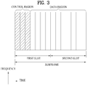
- FIG. 3 illustrates a downlink subframe structure
- a maximum of three (four) OFDM symbols located in a front portion of a first slot within a subframe correspond to a control region to which a control channel is allocated.
- the remaining OFDM symbols correspond to a data region to which a physical downlink shared chancel (PDSCH) is allocated.
- a PDSCH is used to carry a transport block (TB) or a codeword (CW) corresponding to the TB.
- the TB means a data block transmitted from a MAC layer to a PHY layer through a transport channel.
- the codeword corresponds to a coded version of a TB.
- the corresponding relationship between the TB and the CW depends on swiping.
- the PDSCH, TB and CW are interchangeably used.
- Examples of downlink control channels used in LTE include a physical control format indicator channel (PCFICH), a physical downlink control channel (PDCCH), a physical hybrid ARQ indicator channel (PHICH), etc.
- the PCFICH is transmitted at a first OFDM symbol of a subframe and carries information regarding the number of OFDM symbols used for transmission of control channels within the subframe.
- the PHICH is a response of uplink transmission and carries an HARQ acknowledgment (ACK)/not-acknowledgment (NACK) signal.
- ACK HARQ acknowledgment
- NACK not-acknowledgment
- DCI downlink control information
- the DCI includes resource allocation information for a UE or a UE group and other control information.
- the DCI includes uplink/downlink scheduling information, an uplink transmit (Tx) power control command, etc.
- Tx uplink transmit
- Transmission modes and information content of DCI formats for configuring a multi-antenna technology are as follows.
- the PDCCH may carry a transport format and a resource allocation of a downlink shared channel (DL-SCH), resource allocation information of an uplink shared channel (UL-SCH), paging information on a paging channel (PCH), system information on the DL-SCH, information on resource allocation of an upper-layer control message such as a random access response transmitted on the PDSCH, a set of Tx power control commands on individual UEs within an arbitrary UE group, a Tx power control command, information on activation of a voice over IP (Vol P), etc.
- a plurality of PDCCHs can be transmitted within a control region. The UE can monitor the plurality of PDCCHs.
- the PDCCH is transmitted on an aggregation of one or several consecutive control channel elements (CCEs).
- the CCE is a logical allocation unit used to provide the PDCCH with a coding rate based on a state of a radio channel.
- the CCE corresponds to a plurality of resource element groups (REGs).
- a format of the PDCCH and the number of bits of the available PDCCH are determined by the number of CCEs.
- the BS determines a PDCCH format according to DCI to be transmitted to the UE, and attaches a cyclic redundancy check (CRC) to control information.
- CRC cyclic redundancy check
- the CRC is masked with a unique identifier (referred to as a radio network temporary identifier (RNTI)) according to an owner or usage of the PDCCH.
- RNTI radio network temporary identifier
- a unique identifier e.g., cell-RNTI (C-RNTI)
- C-RNTI cell-RNTI
- P-RNTI paging-RNTI
- a system information RNTI (SI-RNTI) may be masked to the CRC.
- SI-RNTI system information RNTI
- RA-RNTI random access-RNTI
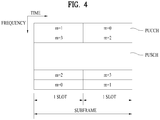
- FIG. 4 illustrates an uplink subframe structure
- an uplink subframe includes a plurality of (e.g. 2) slots.
- a slot may include different numbers of SC-FDMA symbols according to CP lengths.
- the uplink subframe is divided into a control region and a data region in the frequency domain.
- the data region is allocated with a PUSCH and used to carry a data signal such as audio data.
- the control region is allocated a PUCCH and used to carry uplink control information (UCI).
- the PUCCH includes an RB pair located at both ends of the data region in the frequency domain and hopped in a slot boundary.
- the PUCCH can be used to transmit the following control information.
- the quantity of control information (UCI) that a UE can transmit through a subframe depends on the number of SC-FDMA symbols available for control information transmission.
- the SC-FDMA symbols available for control information transmission correspond to SC-FDMA symbols other than SC-FDMA symbols of the subframe, which are used for reference signal transmission.
- SRS Sounding Reference Signal
- the last SC-FDMA symbol of the subframe is excluded from the SC-FDMA symbols available for control information transmission.
- a reference signal is used to detect coherence of the PUCCH.
- the PUCCH supports 7 formats according to information transmitted thereon.
- Table 1 shows the mapping relationship between PUCCH formats and UCI in LTE.
- PUCCH format UCI Uplink Control Information
- Format 1 SR (Scheduling Request) (non-modulated waveform Format 1a 1-bit HARQ ACK/NACK (SR exist/non-exist) Format 1b 2-bit HARQ ACK/NACK (SR exist/non-exist) Format 2 CQI (20 coded bits) Format 2 CQI and 1- or 2-bit HARQ ACK/NACK (20 bits) (corresponding to only extended CP) Format 2a CQI and 1-bit HARQ ACK/NACK (20+1 coded bits) Format 2b CQI and 2-bit HARQ ACK/NACK (20+2 coded bits)
- FIG. 5 illustrates a slot level structure of PUCCH formats la/lb.
- the PUCCH formats la/lb are used for ACK/NACK transmission.
- SC-FDMA symbols #2, #3 and #4 are used for DM RS transmission.
- SC-FDMA symbols #2 and #3 are used for DM RS transmission. Accordingly, 4 SC-FDMA symbols in a slot are used for ACK/NACK transmission.
- PUCCH format la/lb may be called PUCCH format 1 in the description.
- 1-bit [b(0)] and 2-bit [b(0)b(1)] ACK/NACK information are modulated according to BPSK and QPSK modulation schemes respectively, to generate one ACK/NACK modulation symbol d 0 .
- Table 2 shows a modulation table defined for PUCCH formats 1a and 1b in LTE. [Table 2] PUCCH format b(0),...,b(M bit -1) d(0) 1a 0 1 1 1 -1 1b 00 1 01 -j 10 j 11 -1
- PUCCH formats la/lb perform time domain spreading using an orthogonal spreading code W 0 , W 1 , W 2 , W 3 , (e.g. Walsh-Hadamard or DFT code) in addition to cyclic shift ⁇ cs,x in the frequency domain.
- W 0 , W 1 , W 2 , W 3 e.g. Walsh-Hadamard or DFT code
- ⁇ cs,x e.g. Walsh-Hadamard or DFT code
- RSs transmitted from different UEs are multiplexed using the same method as is used to multiplex UCI.
- the number of cyclic shifts supported by SC-FDMA symbols for PUCCH ACK/NACK RB can be configured by cell-specific higher layer signaling parameter ⁇ shift PUCCH .
- ⁇ shift PUCCH ⁇ 1 2,3 represents that shift values are 12, 6 and 4, respectively.
- the number of spreading codes actually used for ACK/NACK can be limited by the number of RS symbols because multiplexing capacity of RS symbols is less than that of UCI symbols due to a smaller number of RS symbols.
- FIG. 6 illustrates an example of determining PUCCH resources for ACK/NACK.
- a plurality of PUCCH resources for ACK/NACK are shared by a plurality of UEs in a cell every time the UEs need the PUCCH resources rather than allocated to UEs in advance.
- a PUCCH resource used by a UE to transmit an ACK/NACK signal corresponds to a PDCCH on which scheduling information on DL data is delivered.
- the region in which the PDCCH is transmitted in a DL subframe is configured with a plurality of Control Channel Elements (CCEs), and the PDCCH transmitted to the UE is composed of one or more CCEs.
- the UE transmits the ACK/NACK signal through a PUCCH resource corresponding to a specific one (e.g. first CCE) of the CCEs constituting the received PDCCH.
- a specific one e.g. first CCE
- each block in a Downlink Component Carrier represents a CCE and each block in an Uplink Component Carrier (UL CC) indicates a PUCCH resource.
- Each PUCCH index corresponds to a PUCCH resource for an ACK/NACK signal. If information on a PDSCH is delivered on a PDCCH composed of CCEs #4, #5 and #6, as shown in FIG. 8 , a UE transmits an ACK/NACK signal on PUCCH #4 corresponding to CCE #4, the first CCE of the PDCCH.
- FIG. 6 illustrates a case in which maximum M PUCCHs are present in the UL CC when maximum N CCEs exist in the DL CC. Though N can equal M, N may differ from M and CCEs are mapped to PUCCHs in an overlapped manner.
- n (1) PUCCH represents a resource index of PUCCH format 1 for ACK/NACK/DTX transmission
- N (1) PUCCH denotes a signaling value received from a higher layer
- n CCE denotes the smallest value of CCE indexes used for PDCCH transmission.
- a cyclic shift, an orthogonal spreading code and a Physical Resource Block (PRB) for PUCCH formats la/lb are obtained from n (1) PUCCH .
- PRB Physical Resource Block
- a UE When an LTE system operates in TDD, a UE transmits one multiplexed ACK/NACK signal for a plurality of PDSCHs received through subframes at different timings. Specifically, the UE transmits one multiplexed ACK/NACK signal for a plurality of PDSCHs using a PUCCH selection transmission scheme. PUCCH selection transmission is also referred to as ACK/NACK channel selection.
- PUCCH selection transmission is also referred to as ACK/NACK channel selection.
- the UE receives a plurality of DL data in PUCCH selection transmission, the UE occupies a plurality of UL physical channels in order to transmit a multiplexed ACK/NACK signal.
- the UE when the UE receives a plurality of PDSCHs, the UE can occupy the same number of PUCCHs as the PDSCHs using a specific CCE of a PDCCH which indicates each PDSCH. In this case, the UE can transmit a multiplexed ACK/NACK signal using combination of which one of the occupied PUCCHs is selected and modulated/coded results applied to the selected PUCCH.
- Table 3 shows a PUCCH selection transmission scheme defined in LTE.
- HARQ-ACK(O), HARQ-ACK(1), HARQ-ACK(2), HARQ-ACK(3) Subframe n PUCCH,X b(0),b(1) ACK, ACK, ACK, ACK n (1) PUCCH,1 1,1 ACK, ACK, ACK, NACK/DTX n (1) PUCCH,1 1,0 NACK/DTX,NACK/DTX,NACK,DTX n (1) PUCCH,2 1,1 ACK, ACK, NACK/DTX, ACK n (1) PUCCH,1 1,0 NACK, DTX, DTX, DTX n (1) PUCCH,0 1,0 ACK, ACK, NACK/DTX, NACK/DTX n (1) PUCCH,0 1,0 ACK, ACK, NACK/DTX, NACK/DTX n (1) PUCCH,1 1,0 ACK, NACK/DTX, ACK, ACK n (1) PUC
- HARQ-ACK(i) indicates the HARQ ACK/NACK/DTX result of an i-th data unit (0 ⁇ i ⁇ 3).
- the HARQ ACK/NACK/DTX result includes ACK, NACK, DTX and NACK/DTX.
- NACK/DTX represents NACK or DTX.
- ACK and NACK represent whether a TB (equivalent to a CW) transmitted through a PDSCH has been successfully decoded or not.
- DTX Discontinuous Transmission
- Maximum 4 PUCCH resources i.e., n (1) PUCCH,0 to n (1) PUCCH,3 ) can be occupied for each data unit.
- the multiplexed ACK/NACK signal is transmitted through one PUCCH resource selected from the occupied PUCCH resources.
- n (1) PUCCH,x represents a PUCCH resource actually used for ACK/NACK transmission
- b(0)b(1) indicates two bits transmitted through the selected PUCCH resource, which are modulated using QPSK.
- the UE transmits bits (1, 1) to a BS through a PUCCH resource linked with n (1) PUCCH,1. Since combinations of PUCCH resources and QPSK symbols cannot represent all available ACK/NACK suppositions, NACK and DTX are coupled except in some cases (NACK/DTX, N/D).
- FIG. 7 illustrates a carrier aggregation (CA) communication system.
- CA carrier aggregation
- an LTE-A system employs CA (or bandwidth aggregation) technology which aggregates a plurality of UL/DL frequency blocks to obtain a wider UL/DL bandwidth.
- Each frequency block is transmitted using a component carrier (CC).
- the CC can be regarded as a carrier frequency (or center carrier, center frequency) for the frequency block.
- a plurality of UL/DL CCs can be aggregated to support a wider UL/DL bandwidth.
- the CCs may be contiguous or non-contiguous in the frequency domain. Bandwidths of the CCs can be independently determined.
- Asymmetrical CA in which the number of UL CCs is different from the number of DL CCs can be implemented. For example, when there are two DL CCs and one UL CC, the DL CCs can correspond to the UL CC in the ratio of 2:1.
- a DL CC/UL CC link can be fixed or semi-statically configured in the system.
- a frequency band that a specific UE can monitor/receive can be limited to M ( ⁇ N) CCs.
- Various parameters with respect to CA can be set cell-specifically, UE-group-specifically, or UE-specifically.
- Control information may be transmitted/received only through a specific CC.
- This specific CC can be referred to as a Primary CC (PCC) (or anchor CC) and other CCs can be referred to as Secondary CCs (SCCs).
- PCC Primary CC
- SCCs Secondary CCs
- a cell is defined as a combination of downlink resources and uplink resources. Yet, the uplink resources are not mandatory. Therefore, a cell may be composed of downlink resources only or both downlink resources and uplink resources.
- the linkage between the carrier frequencies (or DL CCs) of downlink resources and the carrier frequencies (or UL CCs) of uplink resources may be indicated by system information.
- a cell operating in primary frequency resources (or a PCC) may be referred to as a primary cell (PCell) and a cell operating in secondary frequency resources (or an SCC) may be referred to as a secondary cell (SCell).
- PCell primary cell
- SCell secondary cell
- the PCell is used for a UE to establish an initial connection or re-establish a connection.
- the PCell may refer to a cell indicated during handover.
- the SCell may be configured after an RRC connection is established and may be used to provide additional radio resources.
- the PCell and the SCell may collectively be referred to as a serving cell. Accordingly, a single serving cell composed of a PCell only exists for a UE in an RRC_Connected state, for which CA is not set or which does not support CA.
- one or more serving cells exist, including a PCell and entire SCells, for a UE in an RRC _CONNECTED state, for which CA is set.
- a network may configure one or more SCells in addition to an initially configured PCell, for a UE supporting CA during connection setup after an initial security activation operation is initiated.
- FIG. 8 illustrates scheduling when a plurality of carriers is aggregated. It is assumed that 3 DL CCs are aggregated and DL CC A is set to a PDCCH CC.
- DL CC A, DL CC B and DL CC C can be called serving CCs, serving carriers, serving cells, etc.
- a DL CC can transmit only a PDCCH that schedules a PDSCH corresponding to the DL CC without a CIF.
- DL CC A (monitoring DL CC) can transmit not only a PDCCH that schedules the PDSCH corresponding to the DL CC A but also PDCCHs that schedule PDSCHs of other DL CCs.
- DL CC B and DL CC C that are not set to PDCCH CCs do not deliver PDCCHs.
- the DL CC A (PDCCH CC) needs to include all of a PDCCH search space relating to the DL CC A, a PDCCH search space relating to the DL CC B and a PDCCH search space relating to the DL CC C.
- LTE-A considers transmission of a plurality of ACK/NACK information/signals with respect to a plurality of PDSCHs, which are transmitted through a plurality of DL CCs, through a specific UL CC (e.g. UL PCC or UL PCell).
- a UE operates in a SU-MIMO (Single User-Multiple Input Multiple Output) mode in a certain DL CC to receive 2 codewords (or transport blocks).
- the UE needs to be able to transmit 4 feedback states, ACK/ACK, ACK/NACK, NACK/ACK and NACK/NACK, or up to 5 feedback states including even DTX for the DL CC.
- the DL CC is set to support a single codeword (or transport block), up to 3 states of ACK, NACK and DTX are present for the DL CC. Accordingly, if NACK and DTX are processed as the same state, a total of 2 feedback states of ACK and NACK/DTX are present for the DL CC. Accordingly, if the UE aggregates a maximum of 5 DL CCs and operates in the SU-MIMO mode in all CCs, the UE can have up to 55 transmittable feedback states and an ACK/NACK payload size for representing the feedback states corresponds to 12 bits. If DTX and NACK are processed as the same state, the number of feedback states is 45 and an ACK/NACK payload size for representing the same is 10 bits.
- FDD LTE-A discusses transmission of a plurality of ACK/NACK information/signals using PUCCH format 1a/1b and ACK/NACK multiplexing (i.e. ACK/NACK channel selection) where were used in a conventional LTE TDD system in a multicarrier situation.
- the conventional LTE TDD system uses an implicit ACK/NACK selection scheme of using a PUCCH resource corresponding to each PDCCH that schedules each PDSCH (i.e. linked to a lowest CCE index) as an ACK/NACK multiplexing (i.e. ACK/NACK selection) method to secure PUCCH resources.
- the implicit ACK/NACK selection scheme is applied using PUCCH resources in different RBs, performance deterioration may occur.
- LTE-A discusses an explicit ACK/NACK selection scheme that reserves PUCCH resources through RRC signaling, preferably, a plurality of PUCCH resources in the same RB or neighboring RBs, for a UE.
- Table 4 shows an example of explicitly indicating a PUCCH resource for HARQ-ACK.
- a PUCCH resource set can be configured by a higher layer (e.g. RRC) and a PUCCH resource to be actually used can be indicated using an ARI (ACK/NACK Resource Indicator) value of a PDCCH.
- the ARI value can be indicated using a TPC (Transmit Power Control) field of a PDCCH corresponding to a PDSCH on an SCell.
- the ARI value can also be indicated in different manners.
- the ARI value is used interchangeably with a HARQ-ACK resource indication value.
- HARQ-ACK resource value (ARI) for PUCCH n PUCCH 00 First PUCCH resource value configured by a higher layer 01 Second PUCCH resource value configured by a higher layer 10 Third PUCCH resource value configured by a higher layer 11 Fourth PUCCH resource value configured by a higher layer
- a mapping table for ACK/NACK channel selection in LTE-A was designed under the following conditions.
- FIGS. 9 and 10 illustrate a mapping scheme for ACK/NACK channel selection.
- 3-bit ACK/NACK channel selection of LTE-A is based on the assumption that 2 serving cells are aggregated. Accordingly, the 3-bit ACK/NACK channel selection corresponds to a case in which a single SDM (Spatial Division Multiplexing) cell and a single non-SDM cell are aggregated.
- cells and CWs corresponding to HARQ-ACK(O), (1) and (2) depend on an SDM configuration.
- HARQ-ACK(O), (1) and (2) respectively correspond to PCell CW0, PCell CW1 and SCell CW0.
- HARQ-ACK(0), (1) and (2) respectively correspond to SCell CW0, SCell CW1 and PCell CW0. That is, HARQ-ACK(O), (1) and (2) respectively correspond to SDM cell CW0, SDM cell CW1 and non-SDM cell CW0.
- Table 5 shows the corresponding relationship between HARQ-ACKs and CWs in the 3-bit ACK/NACK channel selection scheme.
- a CW is equivalent to a TB.
- Table 5 is based on the TB. [Table 5] HARQ-ACK(j) HARQ-ACK(0) HARQ-ACK(1) HARQ-ACK(2) HARQ-ACK(3) TB1 serving cell 1 TB2 serving cell 1 TB1 serving cell 2 NA
- serving cell 1 represents a cell (i.e. SDM cell) set to a transmission mode supporting transmission of up to 2 TBs and serving cell 2 represents a cell (i.e. non-SDM cell) set to a transmission mode supporting transmission of a single TB.
- PUCCH resources #0 and #1 are implicitly signaled.
- PUCCH resources #0 and #1 can be linked to CCEs (e.g. a lowest CCE index and the lowest CCE index + 1) which constitute a DL grant PDCCH corresponding to a PDSCH of the PCell (refer to Equation 1).
- PUCCH resource #2 can be linked to a CCE (e.g. a lowest CCE index) constituting a DL grant PDCCH corresponding to a PDSCH of an SCell or explicitly signaled by RRC.
- PUCCH resource #2 can be linked to a CCE (e.g. the lowest CCE index) which constitutes the DL grant PDCCH corresponding to the PDSCH of the PCell.
- PUCCH resources #0 and #1 can be linked to CCEs (e.g. the lowest CCE index and the lowest CCE index +1) constituting the DL grant PDCCH corresponding to the PDSCH of the SCell or explicitly signaled by RRC.
- an ACK/NACK/DTX (A/A/D) state is mapped to -1 of PUCCH resource #0 and a NACK/NACK/DTX (N/N/D) state is mapped to +1 of PUCCH resource #0.
- a DTX/DTX/ACK (D/D/A) state is mapped to -1 of PUCCH resource #2 and a DTX/DTX/NACK (D/D/N) state is mapped to +1 of PUCCH resource #2.
- ACK/NACK mapping illustrated in FIG. 9 has been designed to equalize performances of individual ACK/NACK bits by improving worst ACK/NACK bit performance and average performance.
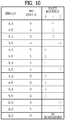
- FIG. 10 shows a 3-bit mapping table configured according to FIG. 9 .
- the UE when a UE receives a PDSCH from a BS, the UE generates HARQ-ACK(O), (1) and (2) according to the SDM configuration of a serving cell.
- the UE selects PUCCH resources (e.g. n PUCCH , i 1 ) corresponding to HARQ-ACK(O), (1) and (2) and transmits bit values (or modulated values) corresponding to HARQ-ACK(O), (1) and (2) to the BS through the selected PUCCH resources.
- PUCCH resources #0 to #2 respectively correspond to n PUCCH , 0 1 ⁇ n PUCCH , 2 1 .
- FIG. 10 assumes QPSK modulation.
- FIGS. 11 and 12 illustrate a mapping scheme for 4-bit ACK/NACK channel selection.
- the 4-bit ACK/NACK channel selection of LTE-A is based on the assumption that 2 serving cells are aggregated. Accordingly, the 4-bit ACK/NACK channel selection corresponds to a case in which 2 SDM cells are aggregated.
- HARQ-ACK(O), (1), (2) and (3) respectively correspond to PCell CW0, PCell CW1, SCell CW0 and SCell CW1.
- Table 6 shows the corresponding relationship between HARQ-ACKs and CWs in the 4-bit ACK/NACK channel selection scheme.
- a CW is equivalent to a TB.
- Table 6 is based on the TB.
- HARQ-ACK(j) HARQ-ACK(0) HARQ-ACK(1) HARQ-ACK(2) HARQ-ACK(3) TB1 primary cell 1 TB2 primary cell 1 TB1 secondary cell 2 TB2 secondary cell 2
- PUCCH resources #0 and #1 are implicitly signaled.
- PUCCH resources #0 and #1 can be linked to CCEs (e.g. the lowest CCE index and the lowest CCE index +1) which constitute the DL grant PDCCH corresponding to the PDSCH of the PCell (refer to Equation 1).
- PUCCH resources #2 and #3 can be linked to CCEs (e.g. the lowest CCE index and the lowest CCE index +1) constituting the DL grant PDCCH corresponding to the PDSCH of the SCell or explicitly signaled by RRC.
- an ACK/NACK/DTX/DTX (A/A/D/D) state is mapped to -1 of PUCCH resource #0 and a NACK/NACK/DTX/DTX (N/N/D/D) state is mapped to +1 of PUCCH resource #0.
- ACK/NACK mapping illustrated in FIG. 11 has been designed to equalize performances of individual ACK/NACK bits by improving worst ACK/NACK bit performance and average performance.
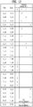
- FIG. 12 shows a 4-bit mapping table configured according to FIG. 11 .
- the UE when the UE receives a PDSCH from the BS, the UE generates HARQ-ACK(O), (1), (2) and (3) according to the SDM configuration of a serving cell.
- the UE selects PUCCH resources (e.g. n PUCCH , i 1 ) corresponding to HARQ-ACK(O), (1), (2) and (3) and transmits bit values (or modulated values) corresponding HARQ-ACK(O), (1), (2) and (3) to the BS through the selected PUCCH resources.
- PUCCH resources #0 to #3 respectively correspond to n PUCCH , 0 1 ⁇ n PUCCH , 3 1 .
- FIG. 12 assumes QPSK modulation.
- mapping schemes/tables for ACK/NACK channel selection described above with reference to FIGS. 9 to 12 have been designed to support only a case in which 2 serving cells are aggregated without spatial bundling. Spatial bundling bundles a plurality of HARQ-ACKs for a plurality of CWs received in a single subframe of a corresponding cell into one HARQ-ACK through a logical AND operation. That is, the mapping schemes/tables for 3-bit/4-bit ACK/NACK channel selection cannot be applied to a case in which three or more serving cells are aggregated. However, application of the conventional mapping schemes/tables for ACK/NACK channel selection is limited because up to 5 CCs (i.e. serving cells) can be aggregated on downlink in LTE-A, as described above with reference to FIG. 7 .
- an ACK/NACK channel selection scheme applicable to even a case in which three or more serving cells are aggregated is required.
- a scheme for applying 3-bit ACK/NACK channel selection to a case in which 3 non-SDM cells are aggregated is needed.
- a scheme for applying 4-bit ACK/NACK channel selection to a case in which one SDM cell and 2 non-SDM cells are aggregated or a case in which 4 non-SDM cells are aggregated is required.
- a non-SDM cell in the above example can be replaced by an SDM cell to which spatial bundling has been applied or an SDM cell group to which spatial bundling/cell bundling has been applied.
- spatial bundling is a scheme for bundling a plurality of HARQ-ACKs for a plurality of CWs received in a subframe of a corresponding cell into one HARQ-ACK through a logical AND operation.
- Cell bundling is a scheme for bundling a plurality of HARQ-ACKs for a plurality of cells into one HARQ-ACK though a logical AND operation.
- mapping table for 3-bit/4-bit ACK/NACK channel selection when three or more serving cells are aggregated.
- a mapping table in case of aggregation of 3 non-SDM cells needs to be additionally defined for 3-bit ACK/NACK channel selection.
- 4-bit ACK/NACK channel selection it is necessary to additionally define mapping tables corresponding to case (1) in which one SDM cell and 2 non-SDM cells are aggregated and case (2) in which 4 non-SDM cells are aggregated.
- HARQ-ACK responses to a non-SDM cell may include ACK, NACK and DTX and HARQ-ACK responses to an SDM cell may include ⁇ ACK, ACK ⁇ , ⁇ ACK, NACK ⁇ , ⁇ NACK, ACK ⁇ , ⁇ NACK, NACK ⁇ and ⁇ DTX ⁇ .
- DTX means PDCCH detection failure, and thus DTX is irrelevant to SDM.
- mapping tables for ACK/NACK channel selection when three or more cells are aggregated can considerably complicate an ACK/NACK feedback process.
- the present invention proposes an efficient ACK/NACK channel selection scheme/mapping table applicable irrespective of cell configuration (e.g. the number of aggregated cells, whether a cell is set to SDM or not, etc.). Specifically, the present invention proposes an ACK/NACK channel mapping scheme for allocating one HARQ-ACK per cell (non-SDM cell or SDM cell to which spatial bundling has been applied) or per cell group (to which spatial bundling and/or cell bundling has been applied) to support ACK/NACK channel selection based ACK/NACK feedback when three or more cells are aggregated.
- the present invention defines only one mapping table for ACK/NACK channel selection per HARQ-ACK (i.e. HARQ-ACK bit) irrespective of cell configuration. That is, a mapping table is defined for each 3-bit/4-bit ACK/NACK channel selection.
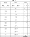
- FIGS. 13 and 14 show mapping tables for ACK/NACK channel selection according to an embodiment of the present invention.
- FIGS. 13 and 14 respectively show 3-bit and 4-bit mapping tables.
- HARQ-ACK(O), (1) and (2) can correspond to the following.
- SDM PCell/SCell denotes a cell corresponding to 2 HARQ-ACKs and non-SDM PCell/SCell denotes a cell (group) corresponding to one HARQ-ACK for convenience. That is, SDM PCell/SCell represents an SDM cell to which spatial bundling is not applied, and non-SDM PCell/SCell represents a non-SDM cell, an SDM cell to which spatial bundling has been applied, a non-SDM SCell group to which cell bundling has been applied, and an SDM SCell group to which spatial bundling/cell bundling has been applied.
- the mapping table for ACK/NACK channel selection according to the present invention can be used for various cell configurations by appropriately coupling NACK and DTX.
- the conventional mapping table for 3-bit ACK/NACK channel selection can be applied in case of only (1) and (2).
- the mapping table for ACK/NACK channel selection according to an embodiment of the present invention can discriminate NACK and DTX from each other and signal the discriminated NACK and DTX to the BS by decoupling NACK and DTX or partially applying coupling for ⁇ NACK, NACK, DTX ⁇ , ⁇ NACK, DTX, DTX ⁇ , ⁇ DTX, NACK, DTX ⁇ and ⁇ DTX, DTX, DTX ⁇ .
- the BS can adjust a redundancy version (RV) when retransmitting a TB by discriminating NACK and DTX from each other.
- RV redundancy version
- Table 7 rearranges the mapping table of FIG. 13 according to the present invention.
- Table 7 HARQ-ACK(0) HARQ-ACK(1) HARQ-ACK(2) n PUCCH , i 1 b(0)b(1) ACK ACK ACK n PUCCH , 1 1 1,1 ACK NACK/DTX ACK n PUCCH , 1 1 1,0 NACK/DTX ACK ACK n PUCCH , 1 1 0,1 NACK/DTX NACK/DTX ACK n PUCCH , 2 1 1,1 ACK ACK NACK/DTX n PUCCH , 0 1 1,1 ACK NACK/DTX NACK/DTX n PUCCH , 0 1 1,0 NACK/DTX ACK NACK/DTX n PUCCH , 0 1 1,0 NACK/DTX ACK NACK/DTX n PUCCH , 0 1 0,1 NACK/DTX NACK/DTX NACK n PUCCH , 2 1 0,0 NACK N
- n PUCCH , 0 1 can be linked to the first CCE index corresponding to the PDCCH relating to the PDSCH of the PCell.
- n PUCCH , 0 1 and n PUCCH , 1 1 can be respectively linked to the first CCE index and the second CCE index of CCEs constituting the PDCCH corresponding to the PDSCH of the PCell.
- n PUCCH , 2 1 can be linked to the first CCE index of the CCE constituting the PDCCH corresponding to the PDSCH of the SCell or explicitly provided by a higher layer.
- Table 8 shows states corresponding to the same PUCCH resource/bit value in Table 7.
- Table 8 HARQ-ACK(0) HARQ-ACK(1) HARQ-ACK(2) n PUCCH , i 1 b(0)b(1) NACK NACK DTX n PUCCH , 0 1 0,0 NACK DTX DTX n PUCCH , 0 1 0,0 DTX NACK DTX n PUCCH , 0 1 0,0
- the states can be bundled.
- the states of Table 8 include a case in which HARQ-ACK(O), (1) and (2) all correspond to DTX, and thus 2 ACK/NACK states are preferably grouped. That is, ⁇ NACK, NACK, DTX ⁇ , ⁇ NACK, NACK, DTX ⁇ and ⁇ NACK, NACK, DTX ⁇ can be bundled into ⁇ NACK/DTX, NACK, DTX ⁇ and ⁇ NACK, NACK/DTX, DTX ⁇ .
- Table 9 shows a case in which the states of Table 8 are bundled in Table 7.
- Table 9 HARQ-ACK(0) HARQ-ACK(1) HARQ-ACK(2) n PUCCH , i 1 b(0)b(1) ACK ACK ACK n PUCCH , 1 1 1,1 ACK NACK/DTX ACK n PUCCH , 1 1 1,0 NACK/DTX ACK ACK n PUCCH , 1 1 0,1 NACK/DTX NACK/DTX ACK n PUCCH , 2 1 1,1 ACK ACK NACK/DTX n PUCCH , 0 1 1,1 ACK NACK/DTX NACK/DTX n PUCCH , 0 1 1,0 NACK/DTX ACK NACK/DTX n PUCCH , 0 1 1,0 NACK/DTX ACK NACK/DTX n PUCCH , 0 1 0,1 NACK/DTX NACK/DTX NACK n PUCCH , 2 1 0,0 NACK
- the UE When the UE receives a PDSCH from the BS, the UE generates HARQ-ACK(O), (1) and (2) according to SDM configuration of a serving cell.
- the UE selects PUCCH resources (e.g. n PUCCH , i 1 ) corresponding to HARQ-ACK(O), (1) and (2) and transmits bit values (or modulated values) corresponding HARQ-ACK(O), (1) and (2) through the selected PUCCH resources.
- PUCCH resources #0, #1 and #2 correspond to n PUCCH , 0 1 ⁇ n PUCCH , 2 1 .
- HARQ-ACK(O), (1), (2) and (3) can correspond to the following.
- SDM PCell/SCell denotes a cell corresponding to 2 HARQ-ACKs and non-SDM PCell/SCell denotes a cell (group) corresponding to one HARQ-ACK for convenience. That is, SDM PCell/SCell represents an SDM cell to which spatial bundling is not applied, and non-SDM PCell/SCell represents a non-SDM cell, an SDM cell to which spatial bundling has been applied, a non-SDM SCell group to which cell bundling has been applied, and an SDM SCell group to which spatial bundling/cell bundling has been applied.
- mapping table for ACK/NACK channel selection can be used for various cell configurations by appropriately coupling NACK and DTX.
- the conventional mapping table for 4-bit ACK/NACK channel selection can be applied in case of only (1).
- the mapping table for ACK/NACK channel selection can discriminate NACK from DTX and signal the determined NACK and DTX to the BS by decoupling NACK and DTX or partially applying coupling for ⁇ NACK, NACK, NACK/DTX, NACK/DTX ⁇ , ⁇ NACK, DTX, NACK/DTX, NACK/DTX ⁇ , ⁇ DTX, NACK, NACK/DTX, NACK/DTX ⁇ and ⁇ DTX, DTX, NACK/DTX, NACK/DTX ⁇ .
- the BS can adjust a redundancy version (RV) when retransmitting a TB by discriminating NACK and DTX from each other.
- RV redundancy version
- Table 10 rearranges the mapping table of FIG. 14 according to the present invention.
- Table 10 HARQ-ACK(0) HARQ-ACK(1) HARQ-ACK(2) HARQ-ACK(3) n PUCCH , i 1 b(0)b(1) ACK ACK ACK ACK n PUCCH , 1 1 1,1 ACK NACK/DTX ACK ACK n PUCCH , 2 1 0,1 NACK/DTX ACK ACK ACK n PUCCH , 1 1 0,1 NACK/DTX NACK/DTX ACK ACK n PUCCH , 3 1 1,1 ACK ACK ACK NACK/DTX n PUCCH , 1 1 1,0 ACK NACK/DTX ACK NACK/DTX n PUCCH , 2 1 0,0 NACK/DTX ACK ACK NACK/DTX n PUCCH , 1 1 0,0 NACK/DTX NACK/DTX n PUCCH , 3 1 1,0 ACK ACK NACK NACK NACK/DT
- n PUCCH , 0 1 and n PUCCH , 1 1 can be respectively linked to the first CCE index and the second CCE index of CCEs constituting the PDCCH corresponding to the PDSCH of the PCell.
- n PUCCH , 2 1 and n PUCCH , 3 1 can be linked to the first CCE index of the CCE constituting the PDCCH(s) relating to the PDSCH(s) of the SCell, which correspond to HARQ-ACK(2) and (3), or explicitly provided by a higher layer.
- Table 11 shows states corresponding to the same PUCCH resource/bit value in Table 10.
- Table 11 HARQ-ACK(0) HARQ-ACK(1) HARQ-ACK(2) HARQ-ACK(3) n PUCCH , i 1 b(0)b(1) NACK DTX NACK/DTX NACK/DTX n PUCCH , 0 1 0,0 DTX NACK NACK/DTX NACK/DTX n PUCCH , 0 1 0,0 NACK NACK NACK/DTX NACK/DTX n PUCCH , 0 1 0,0 NACK NACK NACK/DTX NACK/DTX n PUCCH , 0 1 0,0
- the states can be bundled.
- the states of Table 11 include a case in which HARQ-ACK(O), (1) and (2) all correspond to DTX, and thus 2 ACK/NACK states are preferably grouped. That is, ⁇ NACK, NACK, DTX ⁇ , ⁇ NACK, NACK, DTX ⁇ and ⁇ NACK, NACK, DTX ⁇ can be bundled into ⁇ NACK/DTX, NACK, DTX ⁇ and ⁇ NACK, NACK/DTX, DTX ⁇ .
- Table 12 shows a case in which the states of Table 11 are bundled in Table 10.
- [Table 12] HARQ-ACK(0) HARQ-ACK(1) HARQ-ACK(2) HARQ-ACK(3) n PUCCH , i 1 b(0)b(1) ACK ACK ACK ACK n PUCCH , 1 1 1,1 ACK NACK/DTX ACK ACK n PUCCH , 2 1 0,1 NACK/DTX ACK ACK ACK n PUCCH , 1 1 0,1 NACK/DTX NACK/DTX ACK ACK n PUCCH , 3 1 1,1 ACK ACK ACK NACK/DTX n PUCCH , 1 1 1,0 ACK NACK/DTX ACK NACK/DTX n PUCCH , 2 1 0,0 NACK/DTX ACK ACK NACK/DTX n PUCCH , 1 1 0,0 NACK/DTX NACK/DTX n PUCCH , 3 1 1,0 ACK ACK NACK ACK N
- the UE When the UE receives a PDSCH from the BS, the UE generates HARQ-ACK(O), (1), (2) and (3) according to SDM configuration of a serving cell.
- the UE selects PUCCH resources (e.g. n PUCCH , i 1 ) corresponding to HARQ-ACK(O), (1), (2) and (3) and transmits bit values (or modulated values) corresponding HARQ-ACK(O), (1), (2) and (3) through the selected PUCCH resources.
- PUCCH resources #0 to #3 correspond to n PUCCH , 0 1 ⁇ n PUCCH , 3 1 .
- FIG. 15 illustrates a BS and a UE applicable to an embodiment of the present invention.
- a wireless communication system includes a relay
- communication is performed between a BS and the relay on a backhaul link and between the relay and a UE on an access link.
- the BS or UE shown in FIG. 16 can be replaced by a relay as necessary.
- an RF communication system includes a BS 110 and a UE 120.
- the BS 110 includes a processor 112, a memory 114 and an RF unit 116.
- the processor 112 may be configured to implement the procedures and/or methods proposed by the present invention.
- the memory 114 is connected to the processor 112 and stores various types of information relating to operations of the processor 112.
- the RF unit 116 is connected to the processor 112 and transmits and/or receives RF signals.
- the UE 120 includes a processor 122, a memory 124 and an RF unit 126.
- the processor 122 may be configured to implement the procedures and/or methods proposed by the present invention.
- the memory 124 is connected to the processor 122 and stores various types of information relating to operations of the processor 122.
- the RF unit 126 is connected to the processor 122 and transmits and/or receives RF signals.
- the BS 110 and the UE 120 may have a single antenna or multiple antennas.
- a specific operation described as performed by the BS may be performed by an upper node of the BS.
- various operations performed for communication with an MS may be performed by the BS, or network nodes other than the BS.
- the term 'eNB' may be replaced with the term 'fixed station', 'Node B', 'Base Station (BS)', 'access point', etc.
- the term 'UE' may be replaced with the term 'Mobile Station (MS)', 'Mobile Subscriber Station (MSS)', 'mobile terminal', etc.
- the embodiments of the present invention may be achieved by various means, for example, hardware, firmware, software, or a combination thereof.
- the methods according to the embodiments of the present invention may be achieved by one or more Application Specific Integrated Circuits (ASICs), Digital Signal Processors (DSPs), Digital Signal Processing Devices (DSPDs), Programmable Logic
- ASICs Application Specific Integrated Circuits
- DSPs Digital Signal Processors
- DSPDs Digital Signal Processing Devices
- Programmable Logic Programmable Logic
- PLDs Physical Devices
- FPGAs Field Programmable Gate Arrays
- processors controllers, microcontrollers, microprocessors, etc.
- the embodiments of the present invention may be implemented in the form of a module, a procedure, a function, etc.
- software code may be stored in a memory unit and executed by a processor.
- the memory unit is located at the interior or exterior of the processor and may transmit and receive data to and from the processor via various known means.
- the present invention is applicable to wireless communication apparatuses such as a UE, a relay, a BS, etc.
Landscapes
- Engineering & Computer Science (AREA)
- Signal Processing (AREA)
- Computer Networks & Wireless Communication (AREA)
- Quality & Reliability (AREA)
- Mobile Radio Communication Systems (AREA)
- Detection And Prevention Of Errors In Transmission (AREA)
Priority Applications (1)
| Application Number | Priority Date | Filing Date | Title |
|---|---|---|---|
| EP21188122.2A EP3923497B1 (en) | 2010-10-11 | 2011-10-11 | Method for transmitting control information and apparatus for same |
Applications Claiming Priority (5)
| Application Number | Priority Date | Filing Date | Title |
|---|---|---|---|
| US39202310P | 2010-10-11 | 2010-10-11 | |
| US39293510P | 2010-10-13 | 2010-10-13 | |
| US39248310P | 2010-10-13 | 2010-10-13 | |
| US39331010P | 2010-10-14 | 2010-10-14 | |
| PCT/KR2011/007521 WO2012050340A2 (ko) | 2010-10-11 | 2011-10-11 | 제어 정보를 전송하는 방법 및 이를 위한 장치 |
Related Child Applications (1)
| Application Number | Title | Priority Date | Filing Date |
|---|---|---|---|
| EP21188122.2A Division EP3923497B1 (en) | 2010-10-11 | 2011-10-11 | Method for transmitting control information and apparatus for same |
Publications (3)
| Publication Number | Publication Date |
|---|---|
| EP2629445A2 EP2629445A2 (en) | 2013-08-21 |
| EP2629445A4 EP2629445A4 (en) | 2016-11-16 |
| EP2629445B1 true EP2629445B1 (en) | 2021-08-18 |
Family
ID=45938786
Family Applications (2)
| Application Number | Title | Priority Date | Filing Date |
|---|---|---|---|
| EP11832727.9A Active EP2629445B1 (en) | 2010-10-11 | 2011-10-11 | Method for transmitting control information and apparatus for same |
| EP21188122.2A Active EP3923497B1 (en) | 2010-10-11 | 2011-10-11 | Method for transmitting control information and apparatus for same |
Family Applications After (1)
| Application Number | Title | Priority Date | Filing Date |
|---|---|---|---|
| EP21188122.2A Active EP3923497B1 (en) | 2010-10-11 | 2011-10-11 | Method for transmitting control information and apparatus for same |
Country Status (5)
| Country | Link |
|---|---|
| US (3) | US9491743B2 (ko) |
| EP (2) | EP2629445B1 (ko) |
| JP (2) | JP5932809B2 (ko) |
| KR (1) | KR101797498B1 (ko) |
| WO (1) | WO2012050340A2 (ko) |
Families Citing this family (17)
| Publication number | Priority date | Publication date | Assignee | Title |
|---|---|---|---|---|
| KR101646513B1 (ko) * | 2010-06-16 | 2016-08-08 | 엘지전자 주식회사 | 제어 정보를 전송하는 방법 및 이를 위한 장치 |
| WO2012050340A2 (ko) | 2010-10-11 | 2012-04-19 | 엘지전자 주식회사 | 제어 정보를 전송하는 방법 및 이를 위한 장치 |
| JP5895388B2 (ja) * | 2011-07-22 | 2016-03-30 | シャープ株式会社 | 端末装置、基地局装置、集積回路および通信方法 |
| CN103095433B (zh) * | 2011-11-04 | 2018-06-15 | 北京三星通信技术研究有限公司 | 一种发送harq-ack反馈信息的方法 |
| KR20130125695A (ko) | 2012-05-09 | 2013-11-19 | 주식회사 팬택 | 인터밴드 tdd 전송 방식에서 채널 셀렉션 전송을 위한 harq-ack 인덱스 매핑 및 업링크 자원 할당을 제어하는 방법 및 장치 |
| WO2014081241A1 (ko) * | 2012-11-23 | 2014-05-30 | 엘지전자 주식회사 | 제어 신호 송수신 방법 및 이를 위한 장치 |
| JP6180732B2 (ja) * | 2012-12-17 | 2017-08-16 | 株式会社Nttドコモ | ユーザ端末、無線基地局及び無線通信方法 |
| WO2015041410A1 (ko) * | 2013-09-17 | 2015-03-26 | 엘지전자 주식회사 | 복수의 셀에 동시 접속하는 방법 및 사용자 장치 |
| US10674478B2 (en) * | 2015-08-07 | 2020-06-02 | Sharp Kabushiki Kaisha | Terminal device, communication method, and integrated circuit |
| JP2019506044A (ja) * | 2015-12-31 | 2019-02-28 | 日本電気株式会社 | アップリンク情報を送信および受信する方法および装置 |
| EP3399681A4 (en) * | 2016-01-19 | 2018-12-26 | Huawei Technologies Co., Ltd. | Feedback method and device for uplink channel |
| US11075737B2 (en) | 2016-05-20 | 2021-07-27 | Interdigital Patent Holdings, Inc. | Methods, apparatus, systems and procedures for supporting multicast transmission |
| JP6622163B2 (ja) | 2016-09-13 | 2019-12-18 | 矢崎総業株式会社 | 電池モジュールの電圧検出体及び電池パック |
| CN116032447A (zh) * | 2017-06-14 | 2023-04-28 | Idac控股公司 | 可靠控制信令 |
| CN109152012B (zh) * | 2017-06-16 | 2021-09-03 | 大唐移动通信设备有限公司 | 上行控制信道的发送方法、接收方法、装置、终端及基站 |
| US11445483B2 (en) * | 2017-08-01 | 2022-09-13 | Qualcomm Incorporated | Uplink control channel resource definition and mapping to user equipment |
| EP3737018B1 (en) * | 2018-02-13 | 2023-08-16 | Huawei Technologies Co., Ltd. | Method and apparatus for transmitting uplink control information |
Citations (1)
| Publication number | Priority date | Publication date | Assignee | Title |
|---|---|---|---|---|
| EP2567491A1 (en) * | 2010-05-03 | 2013-03-13 | Alcatel Lucent | Method of providing acknowledgement feedback for aggregated carriers using channel selection and qpsk symbol mapping |
Family Cites Families (39)
| Publication number | Priority date | Publication date | Assignee | Title |
|---|---|---|---|---|
| JPS5932809B2 (ja) | 1980-01-11 | 1984-08-11 | 株式会社日立製作所 | Dmaチヤネルのバス使用権制御方法 |
| JP5504331B2 (ja) * | 2009-03-18 | 2014-05-28 | ノキア シーメンス ネットワークス オサケユキチュア | データをスケジューリングする方法 |
| US8792427B2 (en) * | 2009-05-04 | 2014-07-29 | Qualcomm Incorporated | Transmission of feedback information for data transmissions on multiple carriers |
| CN107104780B (zh) * | 2009-10-01 | 2020-10-16 | 交互数字专利控股公司 | 上行链路控制数据传输 |
| EP2491671B1 (en) * | 2009-10-19 | 2021-06-16 | Samsung Electronics Co., Ltd. | Transmission diversity and multiplexing for harq-ack signals in communication systems |
| CN102237992B (zh) * | 2010-04-30 | 2014-12-10 | 北京三星通信技术研究有限公司 | 一种反馈数据接收状况的方法 |
| WO2011137408A2 (en) * | 2010-04-30 | 2011-11-03 | Interdigital Patent Holdings, Inc. | Determination of carriers and multiplexing for uplink control information transmission |
| BR112012031606B1 (pt) | 2010-06-11 | 2020-11-10 | Ethicon Llc | distribuidor de sutura |
| KR101646513B1 (ko) * | 2010-06-16 | 2016-08-08 | 엘지전자 주식회사 | 제어 정보를 전송하는 방법 및 이를 위한 장치 |
| CN105049149B (zh) * | 2010-07-07 | 2018-09-18 | Lg电子株式会社 | 在无线通信系统中发送控制信息的方法和装置 |
| WO2012008804A2 (ko) * | 2010-07-15 | 2012-01-19 | 엘지전자 주식회사 | 무선 통신 시스템에서 단말의 수신 확인 응답 전송 방법 및 장치 |
| US9100178B2 (en) * | 2010-07-26 | 2015-08-04 | Lg Electronics Inc. | Method and device for transmitting extended uplink control information in wireless communication system |
| CN103026770B (zh) * | 2010-08-13 | 2015-03-11 | 华为技术有限公司 | 用于改善通信系统中的harq反馈的装置及方法 |
| US9112692B2 (en) * | 2010-08-16 | 2015-08-18 | Qualcomm Incorporated | ACK/NACK transmission for multi-carrier operation |
| US8923223B2 (en) * | 2010-08-16 | 2014-12-30 | Qualcomm Incorporated | Physical uplink control channel resource allocation for multiple component carriers |
| US9161349B2 (en) * | 2010-09-13 | 2015-10-13 | Lg Electronics Inc. | Method and device for transmitting control information |
| WO2012036473A2 (ko) * | 2010-09-15 | 2012-03-22 | 엘지전자 주식회사 | 제어 정보를 전송하는 방법 및 이를 위한 장치 |
| CN102404802B (zh) * | 2010-09-16 | 2015-03-11 | 电信科学技术研究院 | 一种应答信息的传输方法、基站及用户终端 |
| WO2012034281A1 (en) * | 2010-09-16 | 2012-03-22 | Huawei Technologies Co., Ltd. | Feedback information relating to a mobile communications system using carrier aggregation |
| US8670410B2 (en) * | 2010-09-17 | 2014-03-11 | Qualcomm Incorporated | Uplink control channel resource mapping for carrier aggregation |
| KR101799275B1 (ko) * | 2010-09-19 | 2017-11-20 | 엘지전자 주식회사 | 제어 정보를 전송하는 방법 및 이를 위한 장치 |
| CN103238278A (zh) * | 2010-10-01 | 2013-08-07 | 捷讯研究有限公司 | 正交资源选择发送分集 |
| KR101801579B1 (ko) * | 2010-10-01 | 2017-11-27 | 엘지전자 주식회사 | 제어 정보를 전송하는 방법 및 이를 위한 장치 |
| US8885496B2 (en) * | 2010-10-08 | 2014-11-11 | Sharp Kabushiki Kaisha | Uplink control information transmission on backward compatible PUCCH formats with carrier aggregation |
| WO2012050340A2 (ko) * | 2010-10-11 | 2012-04-19 | 엘지전자 주식회사 | 제어 정보를 전송하는 방법 및 이를 위한 장치 |
| KR101771550B1 (ko) * | 2010-10-15 | 2017-08-29 | 주식회사 골드피크이노베이션즈 | Ack/nack 신호 송수신 방법 및 장치 |
| CN103222223B (zh) * | 2010-11-18 | 2018-01-30 | Lg电子株式会社 | 发射控制信息的方法及其装置 |
| CN102098151B (zh) * | 2010-12-28 | 2015-08-12 | 中兴通讯股份有限公司 | 一种正确/错误应答消息的发送方法及用户终端 |
| KR101527042B1 (ko) * | 2011-03-21 | 2015-06-09 | 엘지전자 주식회사 | 하향링크 신호 수신방법 및 전송방법과, 사용자기기 및 기지국 |
| EP2515463B1 (en) * | 2011-04-19 | 2020-04-29 | Samsung Electronics Co., Ltd. | Apparatus and method for transmitting acknowledgement information in a tdd communication system |
| KR102029243B1 (ko) * | 2011-05-24 | 2019-10-07 | 엘지전자 주식회사 | 제어 정보를 전송하는 방법 및 이를 위한 장치 |
| US8891353B2 (en) * | 2011-08-11 | 2014-11-18 | Blackberry Limited | Orthogonal resource selection transmit diversity and resource assignment |
| US8897187B2 (en) * | 2011-09-23 | 2014-11-25 | Lg Electronics Inc. | Method for transmitting control information and apparatus for same |
| JP5735713B2 (ja) * | 2011-09-23 | 2015-06-17 | エルジー エレクトロニクス インコーポレイティド | 制御情報を送信する方法及びそのための装置 |
| CN107017973B (zh) * | 2011-09-23 | 2020-05-12 | Lg电子株式会社 | 发送控制信息的方法及用于该方法的设备 |
| CN103843278B (zh) * | 2011-10-06 | 2017-02-15 | Lg电子株式会社 | 发送控制信息的方法和用于该方法的装置 |
| WO2013105837A1 (ko) * | 2012-01-15 | 2013-07-18 | 엘지전자 주식회사 | 무선 통신 시스템에서 제어 정보 전송 방법 및 장치 |
| US8958331B2 (en) * | 2012-07-02 | 2015-02-17 | Intel Corporation | HARQ-ACK handling for unintended downlink sub-frames |
| US10440706B2 (en) * | 2016-08-08 | 2019-10-08 | Sharp Kabushiki Kaisha | Systems and methods for PUCCH resource allocation and HARQ-ACK reporting with processing time reduction |
-
2011
- 2011-10-11 WO PCT/KR2011/007521 patent/WO2012050340A2/ko active Application Filing
- 2011-10-11 JP JP2013533762A patent/JP5932809B2/ja active Active
- 2011-10-11 EP EP11832727.9A patent/EP2629445B1/en active Active
- 2011-10-11 US US13/878,970 patent/US9491743B2/en active Active
- 2011-10-11 EP EP21188122.2A patent/EP3923497B1/en active Active
- 2011-10-11 KR KR1020137011559A patent/KR101797498B1/ko active IP Right Grant
-
2016
- 2016-04-27 JP JP2016089637A patent/JP6405335B2/ja active Active
- 2016-10-03 US US15/284,407 patent/US10292141B2/en active Active
-
2019
- 2019-04-08 US US16/378,059 patent/US10785756B2/en active Active
Patent Citations (1)
| Publication number | Priority date | Publication date | Assignee | Title |
|---|---|---|---|---|
| EP2567491A1 (en) * | 2010-05-03 | 2013-03-13 | Alcatel Lucent | Method of providing acknowledgement feedback for aggregated carriers using channel selection and qpsk symbol mapping |
Also Published As
| Publication number | Publication date |
|---|---|
| EP2629445A4 (en) | 2016-11-16 |
| US20180132226A1 (en) | 2018-05-10 |
| US9491743B2 (en) | 2016-11-08 |
| US10785756B2 (en) | 2020-09-22 |
| EP3923497A1 (en) | 2021-12-15 |
| EP2629445A2 (en) | 2013-08-21 |
| KR20130140708A (ko) | 2013-12-24 |
| JP2016178660A (ja) | 2016-10-06 |
| US20130208691A1 (en) | 2013-08-15 |
| US20190239217A1 (en) | 2019-08-01 |
| WO2012050340A2 (ko) | 2012-04-19 |
| WO2012050340A3 (ko) | 2012-06-14 |
| JP6405335B2 (ja) | 2018-10-17 |
| JP2013543329A (ja) | 2013-11-28 |
| EP3923497B1 (en) | 2023-03-01 |
| JP5932809B2 (ja) | 2016-06-08 |
| US10292141B2 (en) | 2019-05-14 |
| KR101797498B1 (ko) | 2017-11-15 |
Similar Documents
| Publication | Publication Date | Title |
|---|---|---|
| US10785756B2 (en) | Method for transmitting control information and apparatus for same | |
| US9936489B2 (en) | Method for transmitting control information and a device therefor | |
| US9736820B2 (en) | Method and device for transmitting control information | |
| US9848413B2 (en) | Method for transmitting control information and apparatus for same | |
| US9160517B2 (en) | Method for transmitting/receiving signal and device therefor | |
| EP2600549B1 (en) | Method and device for transmitting control information | |
| US9642160B2 (en) | Method and device for transmitting control information | |
| EP2618515B1 (en) | Method and apparatus for transmitting control information | |
| US9014097B2 (en) | Method for transmitting control information and device therefor |
Legal Events
| Date | Code | Title | Description |
|---|---|---|---|
| PUAI | Public reference made under article 153(3) epc to a published international application that has entered the european phase |
Free format text: ORIGINAL CODE: 0009012 |
|
| 17P | Request for examination filed |
Effective date: 20130419 |
|
| AK | Designated contracting states |
Kind code of ref document: A2 Designated state(s): AL AT BE BG CH CY CZ DE DK EE ES FI FR GB GR HR HU IE IS IT LI LT LU LV MC MK MT NL NO PL PT RO RS SE SI SK SM TR |
|
| DAX | Request for extension of the european patent (deleted) | ||
| A4 | Supplementary search report drawn up and despatched |
Effective date: 20161019 |
|
| RIC1 | Information provided on ipc code assigned before grant |
Ipc: H04L 27/26 20060101ALI20161013BHEP Ipc: H04B 7/26 20060101ALI20161013BHEP Ipc: H04L 1/18 20060101AFI20161013BHEP |
|
| STAA | Information on the status of an ep patent application or granted ep patent |
Free format text: STATUS: EXAMINATION IS IN PROGRESS |
|
| 17Q | First examination report despatched |
Effective date: 20190627 |
|
| STAA | Information on the status of an ep patent application or granted ep patent |
Free format text: STATUS: EXAMINATION IS IN PROGRESS |
|
| REG | Reference to a national code |
Ref country code: DE Ref legal event code: R079 Ref document number: 602011071611 Country of ref document: DE Free format text: PREVIOUS MAIN CLASS: H04L0001180000 Ipc: H04L0001000000 |
|
| GRAP | Despatch of communication of intention to grant a patent |
Free format text: ORIGINAL CODE: EPIDOSNIGR1 |
|
| STAA | Information on the status of an ep patent application or granted ep patent |
Free format text: STATUS: GRANT OF PATENT IS INTENDED |
|
| RIC1 | Information provided on ipc code assigned before grant |
Ipc: H04L 1/00 20060101AFI20210210BHEP Ipc: H04L 1/18 20060101ALI20210210BHEP Ipc: H04L 5/00 20060101ALN20210210BHEP Ipc: H04L 27/26 20060101ALI20210210BHEP Ipc: H04L 1/06 20060101ALN20210210BHEP Ipc: H04L 1/16 20060101ALN20210210BHEP Ipc: H04B 7/26 20060101ALI20210210BHEP |
|
| INTG | Intention to grant announced |
Effective date: 20210303 |
|
| RAP3 | Party data changed (applicant data changed or rights of an application transferred) |
Owner name: LG ELECTRONICS INC. |
|
| GRAS | Grant fee paid |
Free format text: ORIGINAL CODE: EPIDOSNIGR3 |
|
| GRAA | (expected) grant |
Free format text: ORIGINAL CODE: 0009210 |
|
| STAA | Information on the status of an ep patent application or granted ep patent |
Free format text: STATUS: THE PATENT HAS BEEN GRANTED |
|
| AK | Designated contracting states |
Kind code of ref document: B1 Designated state(s): AL AT BE BG CH CY CZ DE DK EE ES FI FR GB GR HR HU IE IS IT LI LT LU LV MC MK MT NL NO PL PT RO RS SE SI SK SM TR |
|
| REG | Reference to a national code |
Ref country code: GB Ref legal event code: FG4D |
|
| REG | Reference to a national code |
Ref country code: CH Ref legal event code: EP |
|
| REG | Reference to a national code |
Ref country code: DE Ref legal event code: R096 Ref document number: 602011071611 Country of ref document: DE |
|
| REG | Reference to a national code |
Ref country code: IE Ref legal event code: FG4D Ref country code: AT Ref legal event code: REF Ref document number: 1422589 Country of ref document: AT Kind code of ref document: T Effective date: 20210915 |
|
| REG | Reference to a national code |
Ref country code: LT Ref legal event code: MG9D |
|
| REG | Reference to a national code |
Ref country code: NL Ref legal event code: MP Effective date: 20210818 |
|
| REG | Reference to a national code |
Ref country code: AT Ref legal event code: MK05 Ref document number: 1422589 Country of ref document: AT Kind code of ref document: T Effective date: 20210818 |
|
| PG25 | Lapsed in a contracting state [announced via postgrant information from national office to epo] |
Ref country code: SE Free format text: LAPSE BECAUSE OF FAILURE TO SUBMIT A TRANSLATION OF THE DESCRIPTION OR TO PAY THE FEE WITHIN THE PRESCRIBED TIME-LIMIT Effective date: 20210818 Ref country code: HR Free format text: LAPSE BECAUSE OF FAILURE TO SUBMIT A TRANSLATION OF THE DESCRIPTION OR TO PAY THE FEE WITHIN THE PRESCRIBED TIME-LIMIT Effective date: 20210818 Ref country code: AT Free format text: LAPSE BECAUSE OF FAILURE TO SUBMIT A TRANSLATION OF THE DESCRIPTION OR TO PAY THE FEE WITHIN THE PRESCRIBED TIME-LIMIT Effective date: 20210818 Ref country code: BG Free format text: LAPSE BECAUSE OF FAILURE TO SUBMIT A TRANSLATION OF THE DESCRIPTION OR TO PAY THE FEE WITHIN THE PRESCRIBED TIME-LIMIT Effective date: 20211118 Ref country code: LT Free format text: LAPSE BECAUSE OF FAILURE TO SUBMIT A TRANSLATION OF THE DESCRIPTION OR TO PAY THE FEE WITHIN THE PRESCRIBED TIME-LIMIT Effective date: 20210818 Ref country code: RS Free format text: LAPSE BECAUSE OF FAILURE TO SUBMIT A TRANSLATION OF THE DESCRIPTION OR TO PAY THE FEE WITHIN THE PRESCRIBED TIME-LIMIT Effective date: 20210818 Ref country code: PT Free format text: LAPSE BECAUSE OF FAILURE TO SUBMIT A TRANSLATION OF THE DESCRIPTION OR TO PAY THE FEE WITHIN THE PRESCRIBED TIME-LIMIT Effective date: 20211220 Ref country code: NO Free format text: LAPSE BECAUSE OF FAILURE TO SUBMIT A TRANSLATION OF THE DESCRIPTION OR TO PAY THE FEE WITHIN THE PRESCRIBED TIME-LIMIT Effective date: 20211118 Ref country code: ES Free format text: LAPSE BECAUSE OF FAILURE TO SUBMIT A TRANSLATION OF THE DESCRIPTION OR TO PAY THE FEE WITHIN THE PRESCRIBED TIME-LIMIT Effective date: 20210818 Ref country code: FI Free format text: LAPSE BECAUSE OF FAILURE TO SUBMIT A TRANSLATION OF THE DESCRIPTION OR TO PAY THE FEE WITHIN THE PRESCRIBED TIME-LIMIT Effective date: 20210818 |
|
| PG25 | Lapsed in a contracting state [announced via postgrant information from national office to epo] |
Ref country code: PL Free format text: LAPSE BECAUSE OF FAILURE TO SUBMIT A TRANSLATION OF THE DESCRIPTION OR TO PAY THE FEE WITHIN THE PRESCRIBED TIME-LIMIT Effective date: 20210818 Ref country code: LV Free format text: LAPSE BECAUSE OF FAILURE TO SUBMIT A TRANSLATION OF THE DESCRIPTION OR TO PAY THE FEE WITHIN THE PRESCRIBED TIME-LIMIT Effective date: 20210818 Ref country code: GR Free format text: LAPSE BECAUSE OF FAILURE TO SUBMIT A TRANSLATION OF THE DESCRIPTION OR TO PAY THE FEE WITHIN THE PRESCRIBED TIME-LIMIT Effective date: 20211119 |
|
| PG25 | Lapsed in a contracting state [announced via postgrant information from national office to epo] |
Ref country code: NL Free format text: LAPSE BECAUSE OF FAILURE TO SUBMIT A TRANSLATION OF THE DESCRIPTION OR TO PAY THE FEE WITHIN THE PRESCRIBED TIME-LIMIT Effective date: 20210818 |
|
| PG25 | Lapsed in a contracting state [announced via postgrant information from national office to epo] |
Ref country code: DK Free format text: LAPSE BECAUSE OF FAILURE TO SUBMIT A TRANSLATION OF THE DESCRIPTION OR TO PAY THE FEE WITHIN THE PRESCRIBED TIME-LIMIT Effective date: 20210818 |
|
| REG | Reference to a national code |
Ref country code: DE Ref legal event code: R097 Ref document number: 602011071611 Country of ref document: DE |
|
| REG | Reference to a national code |
Ref country code: CH Ref legal event code: PL |
|
| PG25 | Lapsed in a contracting state [announced via postgrant information from national office to epo] |
Ref country code: SM Free format text: LAPSE BECAUSE OF FAILURE TO SUBMIT A TRANSLATION OF THE DESCRIPTION OR TO PAY THE FEE WITHIN THE PRESCRIBED TIME-LIMIT Effective date: 20210818 Ref country code: SK Free format text: LAPSE BECAUSE OF FAILURE TO SUBMIT A TRANSLATION OF THE DESCRIPTION OR TO PAY THE FEE WITHIN THE PRESCRIBED TIME-LIMIT Effective date: 20210818 Ref country code: RO Free format text: LAPSE BECAUSE OF FAILURE TO SUBMIT A TRANSLATION OF THE DESCRIPTION OR TO PAY THE FEE WITHIN THE PRESCRIBED TIME-LIMIT Effective date: 20210818 Ref country code: EE Free format text: LAPSE BECAUSE OF FAILURE TO SUBMIT A TRANSLATION OF THE DESCRIPTION OR TO PAY THE FEE WITHIN THE PRESCRIBED TIME-LIMIT Effective date: 20210818 Ref country code: CZ Free format text: LAPSE BECAUSE OF FAILURE TO SUBMIT A TRANSLATION OF THE DESCRIPTION OR TO PAY THE FEE WITHIN THE PRESCRIBED TIME-LIMIT Effective date: 20210818 Ref country code: AL Free format text: LAPSE BECAUSE OF FAILURE TO SUBMIT A TRANSLATION OF THE DESCRIPTION OR TO PAY THE FEE WITHIN THE PRESCRIBED TIME-LIMIT Effective date: 20210818 |
|
| REG | Reference to a national code |
Ref country code: BE Ref legal event code: MM Effective date: 20211031 |
|
| PLBE | No opposition filed within time limit |
Free format text: ORIGINAL CODE: 0009261 |
|
| STAA | Information on the status of an ep patent application or granted ep patent |
Free format text: STATUS: NO OPPOSITION FILED WITHIN TIME LIMIT |
|
| PG25 | Lapsed in a contracting state [announced via postgrant information from national office to epo] |
Ref country code: MC Free format text: LAPSE BECAUSE OF FAILURE TO SUBMIT A TRANSLATION OF THE DESCRIPTION OR TO PAY THE FEE WITHIN THE PRESCRIBED TIME-LIMIT Effective date: 20210818 |
|
| 26N | No opposition filed |
Effective date: 20220519 |
|
| PG25 | Lapsed in a contracting state [announced via postgrant information from national office to epo] |
Ref country code: LU Free format text: LAPSE BECAUSE OF NON-PAYMENT OF DUE FEES Effective date: 20211011 Ref country code: IT Free format text: LAPSE BECAUSE OF FAILURE TO SUBMIT A TRANSLATION OF THE DESCRIPTION OR TO PAY THE FEE WITHIN THE PRESCRIBED TIME-LIMIT Effective date: 20210818 Ref country code: BE Free format text: LAPSE BECAUSE OF NON-PAYMENT OF DUE FEES Effective date: 20211031 |
|
| PG25 | Lapsed in a contracting state [announced via postgrant information from national office to epo] |
Ref country code: SI Free format text: LAPSE BECAUSE OF FAILURE TO SUBMIT A TRANSLATION OF THE DESCRIPTION OR TO PAY THE FEE WITHIN THE PRESCRIBED TIME-LIMIT Effective date: 20210818 Ref country code: LI Free format text: LAPSE BECAUSE OF NON-PAYMENT OF DUE FEES Effective date: 20211031 Ref country code: CH Free format text: LAPSE BECAUSE OF NON-PAYMENT OF DUE FEES Effective date: 20211031 |
|
| PG25 | Lapsed in a contracting state [announced via postgrant information from national office to epo] |
Ref country code: FR Free format text: LAPSE BECAUSE OF NON-PAYMENT OF DUE FEES Effective date: 20211018 |
|
| PG25 | Lapsed in a contracting state [announced via postgrant information from national office to epo] |
Ref country code: IE Free format text: LAPSE BECAUSE OF NON-PAYMENT OF DUE FEES Effective date: 20211011 |
|
| PG25 | Lapsed in a contracting state [announced via postgrant information from national office to epo] |
Ref country code: HU Free format text: LAPSE BECAUSE OF FAILURE TO SUBMIT A TRANSLATION OF THE DESCRIPTION OR TO PAY THE FEE WITHIN THE PRESCRIBED TIME-LIMIT; INVALID AB INITIO Effective date: 20111011 Ref country code: CY Free format text: LAPSE BECAUSE OF FAILURE TO SUBMIT A TRANSLATION OF THE DESCRIPTION OR TO PAY THE FEE WITHIN THE PRESCRIBED TIME-LIMIT Effective date: 20210818 |
|
| PGFP | Annual fee paid to national office [announced via postgrant information from national office to epo] |
Ref country code: GB Payment date: 20230905 Year of fee payment: 13 |
|
| PGFP | Annual fee paid to national office [announced via postgrant information from national office to epo] |
Ref country code: DE Payment date: 20230905 Year of fee payment: 13 |
|
| PG25 | Lapsed in a contracting state [announced via postgrant information from national office to epo] |
Ref country code: MK Free format text: LAPSE BECAUSE OF FAILURE TO SUBMIT A TRANSLATION OF THE DESCRIPTION OR TO PAY THE FEE WITHIN THE PRESCRIBED TIME-LIMIT Effective date: 20210818 |