EP2629293A2 - Verfahren und Vorrichtung zur Audiodecodierung - Google Patents
Verfahren und Vorrichtung zur Audiodecodierung Download PDFInfo
- Publication number
- EP2629293A2 EP2629293A2 EP13168293.2A EP13168293A EP2629293A2 EP 2629293 A2 EP2629293 A2 EP 2629293A2 EP 13168293 A EP13168293 A EP 13168293A EP 2629293 A2 EP2629293 A2 EP 2629293A2
- Authority
- EP
- European Patent Office
- Prior art keywords
- band
- signal component
- band signal
- fad
- switch
- Prior art date
- Legal status (The legal status is an assumption and is not a legal conclusion. Google has not performed a legal analysis and makes no representation as to the accuracy of the status listed.)
- Withdrawn
Links
- 238000000034 method Methods 0.000 title claims abstract description 133
- 230000005236 sound signal Effects 0.000 claims abstract description 63
- 230000002194 synthesizing effect Effects 0.000 claims abstract description 16
- 238000007493 shaping process Methods 0.000 claims description 48
- 238000001914 filtration Methods 0.000 claims description 26
- 238000012545 processing Methods 0.000 claims description 20
- 238000013139 quantization Methods 0.000 claims description 8
- 238000013213 extrapolation Methods 0.000 claims description 5
- 230000003139 buffering effect Effects 0.000 claims description 3
- 108010001267 Protein Subunits Proteins 0.000 claims 2
- 238000004590 computer program Methods 0.000 claims 1
- 230000007704 transition Effects 0.000 abstract description 23
- 230000015572 biosynthetic process Effects 0.000 abstract description 18
- 238000003786 synthesis reaction Methods 0.000 abstract description 18
- 238000001514 detection method Methods 0.000 abstract description 9
- 239000010410 layer Substances 0.000 description 33
- 239000000872 buffer Substances 0.000 description 27
- 239000012792 core layer Substances 0.000 description 19
- 230000003595 spectral effect Effects 0.000 description 17
- 238000010586 diagram Methods 0.000 description 10
- 238000005516 engineering process Methods 0.000 description 7
- 230000009897 systematic effect Effects 0.000 description 6
- 230000005540 biological transmission Effects 0.000 description 5
- 238000005070 sampling Methods 0.000 description 4
- 238000012937 correction Methods 0.000 description 3
- 230000003247 decreasing effect Effects 0.000 description 3
- 241000282414 Homo sapiens Species 0.000 description 2
- 230000006978 adaptation Effects 0.000 description 2
- 238000001228 spectrum Methods 0.000 description 2
- 238000012546 transfer Methods 0.000 description 2
- 230000003044 adaptive effect Effects 0.000 description 1
- 230000002238 attenuated effect Effects 0.000 description 1
- 238000004891 communication Methods 0.000 description 1
- 230000007423 decrease Effects 0.000 description 1
- 230000001419 dependent effect Effects 0.000 description 1
- 230000000694 effects Effects 0.000 description 1
- 238000003780 insertion Methods 0.000 description 1
- 230000037431 insertion Effects 0.000 description 1
- 238000003672 processing method Methods 0.000 description 1
- 238000006467 substitution reaction Methods 0.000 description 1
Images






Classifications
-
- G—PHYSICS
- G10—MUSICAL INSTRUMENTS; ACOUSTICS
- G10L—SPEECH ANALYSIS TECHNIQUES OR SPEECH SYNTHESIS; SPEECH RECOGNITION; SPEECH OR VOICE PROCESSING TECHNIQUES; SPEECH OR AUDIO CODING OR DECODING
- G10L19/00—Speech or audio signals analysis-synthesis techniques for redundancy reduction, e.g. in vocoders; Coding or decoding of speech or audio signals, using source filter models or psychoacoustic analysis
- G10L19/04—Speech or audio signals analysis-synthesis techniques for redundancy reduction, e.g. in vocoders; Coding or decoding of speech or audio signals, using source filter models or psychoacoustic analysis using predictive techniques
- G10L19/16—Vocoder architecture
- G10L19/18—Vocoders using multiple modes
- G10L19/24—Variable rate codecs, e.g. for generating different qualities using a scalable representation such as hierarchical encoding or layered encoding
-
- G—PHYSICS
- G10—MUSICAL INSTRUMENTS; ACOUSTICS
- G10L—SPEECH ANALYSIS TECHNIQUES OR SPEECH SYNTHESIS; SPEECH RECOGNITION; SPEECH OR VOICE PROCESSING TECHNIQUES; SPEECH OR AUDIO CODING OR DECODING
- G10L21/00—Speech or voice signal processing techniques to produce another audible or non-audible signal, e.g. visual or tactile, in order to modify its quality or its intelligibility
- G10L21/02—Speech enhancement, e.g. noise reduction or echo cancellation
- G10L21/038—Speech enhancement, e.g. noise reduction or echo cancellation using band spreading techniques
Definitions
- the disclosure relates to the field of voice communications, and more particularly, to a method and apparatus for audio decoding.
- G.729.1 is a new-generation speech encoding and decoding standard newly released by the International Telecommunication Union (ITU).
- ITU International Telecommunication Union
- This embedded speech encoding and decoding standard is best characterized in having a feature of layered encoding, which may provide an audio quality from narrowband to broadband within a rate range of 8kb/s ⁇ 32kb/s.
- an outer-layer code stream may be discarded depending on the channel condition and thus good channel adaptation may be achieved.
- FIG.1 is a block diagram of a G.729.1 system with encoders at each layer.
- the speech codec has a specific encoding process as follows. First, an input signal s WB ( n ) is divided by a Quadrature Mirror Filterbank (QMF) into two sub-bands (H 1 ( z ) , H 2 ( z )).
- QMF Quadrature Mirror Filterbank
- the lower sub-band signal s LB qmf n is pre-processed at a high pass filter having a cut-off frequency of 50 Hz.
- the output signal s LB ( n ) is encoded by an 8kb/s ⁇ 12kb/s narrowband embedded Code-Excited Linear-Prediction (CELP) encoder.
- CELP narrowband embedded Code-Excited Linear-Prediction
- the difference signal d LB ( n ) between s LB ( n ) and a local synthesis signal ⁇ enh ( n ) of the CELP encoder at the rate of 12Kb/s passes through a sense weighting filter (W LB ( z )) to obtain a signal d LB w n .
- the signal d LB w n is subject to a Modified Discrete Cosine Transform (MDCT) to the frequency-domain.
- the weighting filter W LB ( z ) includes gain compensation, to maintain spectral continuity between the output signal d LB w n of the filter and the higher sub-band input signal s HB ( n ).
- the weighted difference signal is transformed to the frequency-domain.
- the higher sub-band component is multiplied with (-1) n to obtain a spectrally inverted signal s HB fold n .
- the spectrally inverted signal s HB fold n is pre-processed after passing through a low pass filter having a cut-off frequency of 3000HZ.
- the filtered signal s HB ( n ) is encoded at a Time-Domain BandWidth Extension (TDBWE) encoder.
- TDBWE Time-Domain BandWidth Extension
- An MDCT transform is performed on s HB ( n ) to the frequency-domain before it enters the Time-domain Alias Cancellation (TDAC) encoding module.
- FIG. 2 is the block diagram of a G.729.1 system having decoders at each layer.
- the operation mode of the decoder is determined by the number of layers of the received code stream, or equivalently, the receiving rate. Detailed descriptions will be made to various cases based on different receiving rates at the receiving side.
- a G.729.1 code stream has a layered structure.
- outer-layer code streams may be discarded from the outer to the inner depending on the channel transmission capability, and thus adaptation to the channel condition may be achieved.
- the decoder might receive a narrowband code stream (equal to or lower than 12kb/s) at a moment when the decoded signal only contains components lower than 4000 Hz and the decoder might receive a broadband code stream (equal to or higher than 14kb/s) at another moment when the decoded signal may contain a broadband signal of 0 ⁇ 7000 Hz.
- bandwidth switch Such a sudden change in bandwidth is referred to as bandwidth switch herein. Since contributions from higher and lower bands to the listening experience are different, such frequent switches may bring noticeable discomfort to the listening experience. In particular, when there are frequent broadband-to-narrowband switches, one will frequently feel that the voice jumps from clearness to tediousness. Therefore, there is a need for a technique to mitigate the discomfort caused by the frequent switches to the listening experience.
- the disclosure provides an audio decoding method and apparatus, to improve over the comfort felt by the human being when a bandwidth switch occurs to a speech signal.
- an audio signal has a switch from broadband to narrowband
- a series of processes such as artificial band extension, time-varying fadeout process, and bandwidth synthesis, may be performed to make the switch to have a smooth transition from a broadband signal to a narrowband signal so that a comfortable listening experience may be achieved.
- FIG. 3 a method for decoding an audio signal is shown in FIG. 3 . Specific steps are included as follows.
- step S301 the frame structure of a received code stream is determined.
- step S302 based on the frame structure of the code stream, detection is made as to whether an audio signal corresponding to the code stream has a switch from a first bandwidth to a second bandwidth which is narrower than the first bandwidth. If there is such a switch, step S303 is performed. Otherwise, the code stream is decoded according to a normal decoding flow and the reconstructed audio signal is output.
- a narrowband signal generally refers to a signal having a frequency band of 0 ⁇ 4000 Hz and a broadband signal refers to a signal having a frequency band of 0 ⁇ 8000 Hz.
- An ultra wideband (UWB) signal refers to a signal having a frequency band of 0 ⁇ 16000 Hz.
- a signal having a wider band may be divided into a lower-band signal component and a higher-band signal component.
- the higher-band signal component in the embodiments of the invention may refer to the part added after the switch with respect to the bandwidth before the switch, and the narrowband signal component may refer to the part having a bandwidth common to both the audio signals before and after the switch.
- the lower-band signal component may refer to the signal of 0 ⁇ 4000 Hz and the higher-band signal component may refer to the signal of 4000 ⁇ 8000 Hz.
- step S303 when detecting that the audio signal corresponding to the code stream switches from the first bandwidth to the second bandwidth, the received lower-band coding parameter is used for decoding, to obtain a lower-band signal component.
- the solution in the embodiments of the invention may be applied as long as the bandwidth before the switch is wider than the bandwidth after the switch, and it is not limited to a broadband-to-narrowband switch in the general sense.
- step S304 an artificial band extension technique is used to extend the lower-band signal component, so as to obtain higher-band information.
- the higher-band information may be a higher-band signal component or a higher-band coding parameter.
- the lower-band signal component may be used to extend the lower-band signal component to obtain higher-band information; or, a lower-band signal component decoded from the current audio frame after the switch may be extended to obtain higher-band information.
- the method of employing a higher-band coding parameter received before the switch to extend the lower-band signal component to obtain higher-band information may include: buffering a higher-band coding parameter received before the switch (for example, the time-domain and frequency-domain envelopes in the TDBWE encoding algorithm or the MDCT coefficients in the TDAC encoding algorithm); and estimating the higher-band coding parameter of the current audio frame by using extrapolation after the switch. Further, according to the higher-band coding parameter, a corresponding broadband decoding algorithm may be used to obtain the higher-band signal component.
- the method of employing a lower-band signal component decoded from the current audio frame after the switch to obtain higher-band information may include: performing a Fast Fourier Transform (FFT) on the lower-band signal component decoded from the current audio frame after the switch; extending and shaping the FFT coefficients of the lower-band signal component within the FFT domain, the shaped FFT coefficients as the FFT coefficients of the higher-band information; performing an inverse FFT transform, to obtain the higher-band signal component.
- FFT Fast Fourier Transform
- a time-varying fadeout process is performed on the higher-band information obtained through extension.
- the fadeout process refers to the transition of the audio signal from the first bandwidth to the second bandwidth.
- the method of performing a time-varying fadeout process on the higher-band information may include a separate time-varying fadeout process and a hybrid time-varying fadeout process.
- the separate time-varying fadeout process may involve a first method in which a time-domain shaping is performed on the higher-band information obtained through extension by using a time-domain gain factor and further a frequency-domain shaping may be performed on the time-domain shaped higher-band information by using time-varying filtering; or a second method in which a frequency-domain shaping is performed on the higher-band information obtained through extension by using time-varying filtering and further a time-domain shaping may be performed on the frequency-domain shaped higher-band information by using a time-domain gain factor.
- the hybrid time-varying fadeout process may involve a third method in which a frequency-domain shaping is performed on the higher-band coding parameter obtained through extension by using a frequency-domain higher-band parameter time-varying weighting method, to obtain a time-varying fadeout spectral envelope, and the processed higher-band signal component is obtained through decoding; or a fourth method in which the higher-band signal component obtained through extension is divided into sub-bands, and a frequency-domain higher-band parameter time-varying weighting is performed on the coding parameter of each sub-band to obtain a time-varying fadeout spectral envelope and the processed higher-band signal component is obtained through decoding.
- step S306 the processed higher-band signal component and the decoded lower-band signal component are synthesized.
- the decoder may perform the time-varying fadeout process on the higher-band information obtained through extension in many methods. Detailed descriptions will be made below to the specific embodiments of different time-varying fadeout processing method.
- the code stream received by the decoder may be a speech segment.
- the speech segment refers to a segment of speech frames received by the decoder consecutively.
- a speech frame may be a full rate speech frame or several layers of the full rate speech frame.
- the code stream received by the decoder may be a noise segment which refers to a segment of noise frames received by the decoder consecutively.
- a noise frame may be a full rate noise frame or several layers of the full rate noise frame.
- the code stream received by the decoder is a speech segment and the time-varying fadeout process uses the first method.
- a time-domain shaping is performed on the higher-band information obtained through extension by using a time-domain gain factor and further a frequency-domain shaping may be performed on the time-domain shaped higher-band information by using time-varying filtering.
- a method for decoding an audio signal is shown in FIG. 4 , and may include specific steps as follows.
- step S401 the decoder receives a code stream transmitted from the encoder, and determines the frame structure of the received code stream.
- the encoder encodes the audio signal according to the flow as shown in the systematic block diagram of FIG. 1 , and transmits the code stream to the decoder.
- the decoder receives the code stream. If the audio signal corresponding to the code stream has no switch from broadband to narrowband, the decoder may decode the received code stream as normal according to the flow shown in the systematic block diagram of FIG. 2 . No repetition is made here.
- the code stream received by decoder is a speech segment.
- a speech frame in the speech segment may be a full rate speech frame or several layers of the full rate speech frame. In this embodiment, a full rate speech frame is used and its frame structure is shown in Table 1.
- step S402 the decoder detects whether a switch from broadband to narrowband occurs according to the frame structure of the code stream. If such a switch occurs, the flow proceeds with step S403. Otherwise, the code stream is decoded according to the normal decoding flow and the reconstructed audio signal is output.
- detection may be made as to whether the current speech segment has a switch from broadband to narrowband.
- step S403 when the speech signal corresponding to the received code stream switches from broadband to narrowband, the decoder decodes the received lower-band coding parameter by using the embedded CELP, so as to obtain a lower-band signal component s ⁇ LB post n .
- step S404 the coding parameter of the higher-band signal component received before the switch may be employed to extend the lower-band signal s ⁇ LB post n , so before the switch may be employed to extend the lower-band signal component s ⁇ LB post n , so as to obtain a higher-band signal component ⁇ HB ( n )
- the decoder after receiving a speech frame having a higher-band coding parameter, the decoder buffers the TDBWE coding parameter (including the time-domain envelope and the frequency-domain envelope) of M speech frames received before the switch each time. After detecting a switch from broadband to narrowband, the decoder first extrapolates the time-domain envelope and frequency-domain envelope of the current frame based on the time-domain envelope and frequency-domain envelope of the speech frames received before the switch stored in the buffer, and then performs TDBWE decoding by using the extrapolated time-domain envelope and frequency-domain envelope to obtain the higher-band signal component through extension.
- the decoder After detecting a switch from broadband to narrowband, the decoder first extrapolates the time-domain envelope and frequency-domain envelope of the current frame based on the time-domain envelope and frequency-domain envelope of the speech frames received before the switch stored in the buffer, and then performs TDBWE decoding by using the extrapolated time-domain envelope and frequency-domain envelope to obtain the higher-band signal component through extension.
- the decoder may buffer the TDAC coding parameter of M speech frames received before the switch (i.e., the MDCT coefficients), extrapolates the MDCT coefficients of the current frame, and then performs TDAC decoding by using the extrapolated MDCT coefficients to obtain the higher-band signal component through extension.
- the synthesis parameter of the higher-band signal component may be estimated with a mirror interpolation method.
- the higher-band coding parameters of the M recent speech frames buffered in the buffer are used as a mirror source to perform a segment linear interpolation, starting from the current speech frame.
- P k represents the synthesis parameter for higher-band signal component of the k th speech frame reconstructed from the switching position
- N the number of speech frames for which the fadeout process is performed
- P -i represents the higher-band coding parameter of the i th speech frame received before the switching position stored in the buffer
- i 1, ⁇ , M
- M is the number of frames buffered for the fadeout process
- ( a )mod( b ) represents a MOD operation of a with b
- ⁇ • ⁇ represents a floor operation.
- the higher-band coding parameters of M buffered speech frames before the switch may be used to estimate the higher-band coding parameters of N speech frames after the switch.
- the higher-band signal components of N speech frames after the switch may be reconstructed with a TDBWE or TDAC decoding algorithm.
- M may be any value less than N.
- step S405 a time-domain shaping is performed on the higher-band signal component obtained through extension ⁇ HB ( n ), to obtain a processed higher-band signal component s ⁇ HB ts n .
- a time-varying gain factor g ( k ) may be introduced.
- the changing curve of the time-varying factor is shown in FIG. 5 .
- the time-varying gain factor has a linearly attenuated curve in the logarithm domain.
- a frequency-domain shaping may be performed on the time-domain shaped higher-band signal component s ⁇ HB ts n by using time-varying filtering, to obtain the frequency-domain shaped higher-band signal s ⁇ HB fad n . obtain the frequency-domain shaped higher-band signal component s ⁇ HB fad n .
- the time-domain shaped higher-band signal component s ⁇ HB ts n passes through a time-varying filter so that the frequency band of the higher-band signal component becomes narrower slowly over time.
- the time-varying filter used in this embodiment is a time-varying order 2 Butterworth filter having a zero point fixed at -1 and a pole point changing constantly.
- FIG. 6 shows the change in the pole point of the time-varying order 2 Butterworth filter.
- the pole point of the time-varying filter moves clockwise. In other words, the pass band of the filter decreases until to reach 0.
- the broadband-to-narrowband switching flag fad_out_flag is set to 0, and the counter of the points of the filter fad_out_count is set to 0.
- the narrowband-to-broadband switching flag fad_out_flag is set to 1, and the time-varying filter is enabled to start filtering the reconstructed higher-band signal component.
- the time-varying filter has a precise pole point of rel ( i ) + img ( i ) ⁇ j at moment i and the pole point moves to rel ( m ) + img ( m ) ⁇ j precisely at moment m.
- the point number of interpolation is N
- the filter counter When the decoder receives a broadband speech signal, the counter of the points of the filter fad_out_count is set to 0.
- the filter counter When the speech signal received by the decoder switches from broadband to narrowband, the time-varying filter is enabled, and the filter counter may be updated as follows:
- the time-domain shaped reconstructed higher-band signal component s ⁇ HB ts n is the input signal of the time-varying is the signal of the filter, and s ⁇ HB fad n is the output signal of the time-varying filter.
- s ⁇ HB fad n gain_filter ⁇ a 1 ⁇ s ⁇ HB fad ⁇ n - 1 + a 2 ⁇ s ⁇ HB fad ⁇ n - 2 + s ⁇ HB ts + 2.0 ⁇ s ⁇ HB ts ⁇ n - 1 + s ⁇ HB ts ⁇ n - 2
- a QMF filter bank may be used to perform a synthesis filtering on the decoded lower-band signal component s ⁇ LB post n and the processed higher-band signal component s ⁇ HB fad n (the higher-band signal component s ⁇ HB ts n if step S406 is not performed).
- a time-varying fadeout signal may be reconstructed, which meets the characteristics of a smooth transition from broadband to narrowband.
- the time-varying fadeout processed higher-band signal component s ⁇ HB fad n and the reconstructed lower-band signal component s ⁇ LB post n are input together to the QMF filter bank for synthesis filtering, to obtain a full band reconstructed signal. Even if there are frequent switches from broadband to narrowband during decoding, the reconstructed signal processed according to the invention can provide a relatively better listening quality to the human beings.
- the time-varying fadeout process of the speech segment uses the first method, that is, a time-domain shaping is performed on the higher-band information obtained through extension by using a time-domain gain factor, and a frequency-domain shaping is performed on the time-domain shaped higher-band information by using time-varying filtering.
- the time-varying fadeout process may use other alternative methods.
- the code stream received by the decoder is a speech segment and the time-varying fadeout process uses the third method, that is, a frequency-domain higher-band parameter time-varying weighting method is used to perform a frequency-domain shaping on the higher-band information obtained through extension.
- a method for decoding an audio signal is shown in FIG. 7 , including steps as follows.
- Steps S701-S703 are similar to steps S401-S403 in the second embodiment, and thus no repetition is made here.
- step S704 the coding parameter of a higher-band signal component received before the switch is used to extend the lower-band signal component s ⁇ LB post n , to obtain the higher-band coding parameter.
- the higher-band coding parameter of M speech frames before the switch buffered in the decoder may be used to estimate the higher-band coding parameter of N speech frames after the switch (the frequency-domain envelope and the higher-band spectral envelope).
- the TDBWE coding parameters of the M speech frames received before the switch may be buffered each time, including coding parameters such as the time-domain envelope and the frequency-domain envelope.
- the decoder Upon detection of a switch from broadband to narrowband, the decoder first obtains the time-domain envelope and the frequency-domain envelope of the current frame through extrapolation based on the time-domain envelope and the frequency-domain envelope received before the switch stored in the buffer.
- the decoder may buffer the TDAC coding parameter (i.e., MDCT coefficients) of the M speech frames received before the switch, and obtains the higher-band coding parameter through extension based on the MDCT coefficients of the speech frame.
- a mirror interpolation method may be used to estimate the synthesis parameter of the higher-band signal component.
- the higher-band coding parameter frequency-domain envelope and higher-band spectral envelope
- M frequency-domain envelope and higher-band spectral envelope
- the buffered higher-band coding parameters of the M frames before the switch may be used to estimate the higher-band coding parameters (frequency-domain envelope and higher-band spectral envelope) of the N frames after the switch.
- a frequency-domain higher-band parameter time-varying weighting method may be used to perform a frequency-domain shaping on the higher-band coding parameter obtained through extension.
- the higher-band signal is divided into several sub-bands in the frequency-domain, and then a frequency-domain weighting is performed on the higher-band coding parameter of each sub-band with a different gain so that the frequency band of the higher-band signal component becomes narrower slowly.
- the broadband coding parameter no matter the frequency-domain envelope in the TDBWE encoding algorithm at 14kb/s or the higher-band envelope in the TDAC encoding algorithm at a rate of more than 14kb/s, may imply a process of dividing the higher-band into a number of sub-bands.
- the narrowband-to-broadband switching flag fad_out_flag is set to 0, and the counter of transition frames fad_out_frame_count is set to 0. From a certain moment, when the decoder starts to process a speech signal of 8kb/s or 12 kb/s, the narrowband-to-broadband switching flag fad_out_flag is set to 1. When the counter of transition frames fad_out_frame_count meets the condition fad_out_frame_count ⁇ N, the coding parameter is weighted within the frequency-domain and the weighting factor changes over time.
- the coding parameters of the higher-band signal component received and buffered in the buffer may include a higher-band envelope within the MDCT domain and a frequency-domain envelope in the TDBWE algorithm. Otherwise, the higher-band signal coding parameters received and buffered in the buffer only include a frequency-domain envelope in the TDBWE algorithm.
- the higher-band coding parameters in the buffer may be used to reconstruct the corresponding higher-band coding parameter of the current frame, the frequency-domain envelope or the higher-band envelope in the MDCT domain. These envelopes in the frequency-domain divide the entire higher-band into several sub-bands.
- Each sub-band is weighted according to a time-varying fadeout gain factor gain ( k,j ), i.e., F ⁇ env ( J ) . gain ( k,j ).
- TDBWE frequency-domain envelope and the MDCT domain higher-band envelope may be decoded by using a TDBWE decoding algorithm and a TDAC decoding algorithm respectively.
- a time-varying fadeout higher-band signal component s ⁇ HB fad n may be obtained.
- a QMF filter bank may perform a synthesis filtering on the processed higher-band signal component s ⁇ HB fad n and the decoded lower-band signal component s ⁇ LB post n , to reconstruct a time-varying fadeout signal.
- the audio signal may include a speech signal and a noise signal.
- the speech segment switches from broadband to narrowband.
- the noise segment may also switch from broadband to narrowband.
- the code stream received by the decoder is a noise segment and the time-varying fadeout process uses the second method.
- a frequency-domain shaping is performed by using time-varying filtering on the higher-band information obtained through extension, and further a time-domain shaping may be performed on the frequency-domain shaped higher-band information by using a time-domain gain factor.
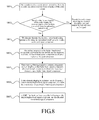
- FIG. 8 A method for decoding an audio signal is shown in FIG. 8 , including steps as follows.
- step S801 the decoder receives a code stream transmitted from the encoder, and determines the frame structure of the received code stream.
- the encoder encodes the audio signal according to the flow as shown in the systematic block diagram of FIG. 1 , and transmits the code stream to the decoder.
- the decoder receives the code stream. If the audio signal corresponding to the code stream has no switch from broadband to narrowband, the decoder may decode the received code stream as normal according to the flow as shown in the systematic block diagram of FIG. 2 . No repetition is made here.
- the code stream received by decoder is a speech segment.
- a speech frame in the speech segment may be a full rate speech frame or several layers of the full rate speech frame.
- the noise frame may be encoded and transmitted continuously, or may use the discontinuous transmission (DTX) technology. In this embodiment, the noise segment and the noise frame may have the same definition.
- the noise frame received by the decoder is a full rate noise frame
- the encoding structure of the noise frame used in this embodiment is shown in Table 2.
- Table 2 Parameter description Bit allocation Layered structure LSF parameter quantizer index 1 Narrowband core layer Level 1 LSF quantized vector 5 Level 2 LSF quantized vector 4 Energy parameter quantized value 5 Energy parameter level 2 quantized value 3 Narrowband enhancement layer Level 3 LSF quantized vector 6 Broadband component time-domain envelope 6 Broadband core layer Broadband component frequency-domain envelope vector 1 5 Broadband component frequency-domain envelope vector 2 5 Broadband component frequency-domain envelope Vector 3 4
- step S802 the decoder detects whether a switch from broadband to narrowband occurs according to the frame structure of the code stream. If such a switch occurs, the flow proceeds with step S803. Otherwise, the code stream is decoded according to the normal decoding flow and the reconstructed noise signal is output.
- the decoder may determine whether a switch from broadband to narrowband occurs according to the data length of the current frame. For example, if the data of the current frame only contains a narrowband core layer or a narrowband core layer plus a narrowband enhancement layer, that is, the length of the current frame is 15 bits or 24 bits, the current frame is narrowband. Otherwise, if the data of the current frame further contains a broadband core layer, that is, the length of the current frame is 43 bits, the current frame is broadband.
- detection may be made as to whether a switch from broadband to narrowband is occurring currently.
- a Silence Insertion Descriptor (SID) frame received by the decoder contains a higher-band coding parameter (i.e., a broadband core layer)
- the higher-band coding parameter in the buffer is updated with the SID frame.
- the decoder may determine that a switch from broadband to narrowband occurs.
- step S803 when the noise signal corresponding to the received code stream switches from broadband to narrowband, the decoder decodes the received lower-band coding parameter by using the embedded CELP, to obtain a lower-band signal component s ⁇ LB post n .
- step S804 by using the coding parameter of the higher-band signal component received before the switch, the lower-band signal s ⁇ LB post n is extended to obtain a higher-band signal component ⁇ HB ( n ) .
- the two most recent SID frames containing a higher-band coding parameter (frequency-domain envelope) buffered in the buffer may be taken as the mirror source, to perform a segment linear interpolation starting from the current frame. Equation (3) is used to reconstruct the higher-band coding parameter of the k th noise frame after the switch from broadband to narrowband.
- P k k N - 1 ⁇ P sid_past + 1 - k N - 1 ⁇ P sid_p_past
- P sid_past represents the higher-band coding parameter of the most recent SID frame containing a broadband core layer stored in the buffer
- P sid_past represents the higher-band coding parameter of the next most recent SID frame containing a broadband core layer stored in the buffer.
- the buffered higher-band coding parameter of two noise frames before the switch may be used to estimate the higher-band coding parameter (frequency-domain envelope) of the N noise frames after the switch, so as to recover the higher-band signal component of the N noise frames after the switch.
- the higher-band coding parameter reconstructed with equation (3) may be extended to obtain the higher-band signal component ⁇ HB ( n ) .
- step S805 time-varying filtering is used to perform a frequency-domain shaping on the higher-band signal component obtained through extension ⁇ HB ( n ) , to obtain a frequency-domain shaped higher-band signal component s ⁇ HB fad n .
- the higher-band signal component obtained through extension ⁇ HB ( n ) passes through a time-varying filter so that the frequency band of the higher-band signal component becomes narrower slowly over time.
- FIG. 6 shows the change in the pole point of the filter.
- the broadband-to-narrowband switching flag fad_out_flag is set to 0 and the counter of the filter points fad_out_flag is set to 0.
- the narrowband-to-broadband switching flag fad_out_flag is set to 1.
- time-varying filter is enabled to filter the reconstructed higher-band signal component.
- fad_out_count meets the condition fad_out_count ⁇ FAD_OUT_COUNT_MAX
- time-varying filtering is performed continuously. Otherwise, the time-varying filter process is stopped.
- the time-varying filter has a precise pole point of rel ( i ) + img ( i ) ⁇ j at moment i and the pole point moves to rel ( m ) + img ( m ) ⁇ j precisely at moment m.
- the counter of the filter fad_out_count is set to 0.
- the time-varying filter is enabled and the filter counter may be updated as follows:
- s ⁇ HB fad n gain_filter ⁇ a 1 ⁇ s ⁇ HB fad ⁇ n - 1 + a 2 ⁇ s ⁇ HB fad ⁇ n - 2 + s ⁇ HB n + 2.0 ⁇ s ⁇ HB ⁇ n - 1 + s ⁇ HB ⁇ n - 2
- a time-domain shaping may be performed on the frequency-domain shaped higher-band signal component s ⁇ HB fad n , to obtain a time-domain shaped higher-band signal component s ⁇ HB ts n .
- a time-varying gain factor g ( k ) may be introduced.
- the changing curve of the time-varying factor is shown in FIG. 5 .
- the higher-band signal component obtained through extension after the TDBWE or TDAC decoding is multiplied with a time-varying gain factor, as shown in equation (2).
- This implementation is similar to the process of performing time-domain shaping on the higher-band signal component in the second embodiment, and thus no repetition is made here.
- the time-varying gain factor in this step may be multiplied with the filter gain in the step S805. The two methods may obtain the same result.
- a QMF filter bank may be used to perform a synthesis filtering on the decoded lower-band signal s ⁇ LB post n and the shaped higher-band signal component decoded lower-band signal component s ⁇ LB post n and the shaped higher-band signal component s ⁇ HB ts n (the higher-band signal component s ⁇ HB fad n if step S806 is not performed).
- a time-varying fadeout signal may be reconstructed, which meets the characteristics of a smooth transition from broadband to narrowband.
- the time-varying fadeout process of the noise segment uses the second method, that is, a frequency-domain shaping is performed on the higher-band information obtained through extension by using time-varying filtering and further a time-domain shaping may be performed on the frequency-domain shaped higher-band information by using a time-domain gain factor.
- the time-varying fadeout process may use other alternative methods.
- the code stream received by the decoder is a noise segment and the time-varying fadeout process uses the fourth method, that is, the higher-band information obtained through extension is divided into sub-bands, and a frequency-domain higher-band parameter time-varying weighting is performed on the coding parameter of each sub-band.
- An audio decoding method is shown in FIG. 9 , including steps as follows.
- Steps S901-S903 are similar to steps S801- S803 in the fourth embodiment, and thus no repetition is made here.
- step S904 the coding parameter of the higher-band signal component received before the switch (including but not limited to the frequency-domain envelope) may be used to obtain the higher-band coding parameter through extension.
- the synthesis parameter of the higher-band signal component may be estimated with a mirror interpolation method.
- the noise frame uses the DTX technology
- the two most recent SID frames containing a higher-band coding parameter (frequency-domain envelope) buffered in the buffer may be taken as the mirror source, to perform segment linear interpolation starting from the current frame. Equation (3) may be used to reconstruct the higher-band coding parameter of the k th frame after the switch from broadband to narrowband.
- the above higher-band coding parameter obtained through extension might not be divided into sub-bands.
- the higher-band coding parameter obtained through extension may be decoded to obtain a higher-band signal component, and a higher-band coding parameter may be extracted from the higher-band signal component obtained through extension, for performing frequency-domain shaping.
- step S905 the higher-band coding parameter obtained through extension is decoded to obtain a higher-band signal component.
- frequency-domain envelopes may be extracted from the higher-band signal component obtained through extension by using a TDBWE algorithm. These frequency-domain envelopes may divide the entire higher-band signal component into a series of nonoverlapping sub-bands.
- step S907 frequency-domain higher-band parameter time-varying weighting is used to perform a frequency-domain shaping on the extracted frequency-domain envelope.
- the frequency-domain shaped frequency-domain envelope is decoded to obtain a processed higher-band signal component.
- a time-varying weighting process is performed on the extracted frequency-domain envelope.
- the frequency-domain envelopes are equivalent to dividing the higher-band signal component into several sub-bands in the frequency-domain, and thus frequency-domain weighting is performed on each frequency-domain envelope with a different gain so that the signal band becomes narrower slowly.
- the decoder successively receives SID frames containing the higher-band coding parameter, it may be considered to be in the broadband noise signal phase.
- the broadband-to-narrowband switching flag fad_out_flag is set to 0, and the counter of the transition frames fad_out_frame_count is set to 0.
- the decoder determines that a switch from broadband to narrowband occurs.
- the broadband-to-narrowband switching flag fad_out_flag is set to 1.
- fad_out_frame_count meets the condition fad_out_frame_count ⁇ N
- the frequency-domain envelope of each sub-band is weighted by using a time-varying fadeout gain factor gain ( k,j ), that is, F ⁇ env ( j ). gain ( k,j ).
- the time-varying fadeout spectral envelope may be obtained in the frequency-domain.
- the time-varying fadeout TDBWE frequency-domain envelope may be decoded with the TDBWE decoding algorithm to obtain a processed time-varying fadeout higher-band signal component.
- a QMF filter bank may perform a synthesis filtering on the processed higher-band signal component and the decoded lower-band signal component s ⁇ LB post n , to reconstruct the time-varying fadeout signal.
- the speech segment or noise segment corresponding to the code stream received by the decoder switches from broadband to narrowband. It may be understood that there may be two cases as follows. The speech segment corresponding to the code stream received by the decoder switches from broadband to narrowband, and after the switch, the decoder can still receive the noise segment corresponding to the code stream. Or, the noise segment corresponding to the code stream received by the decoder switches from broadband to narrowband, and after the switch, the decoder can still receive the speech segment corresponding to the code stream.
- the speech segment corresponding to the code stream received by the decoder switches from broadband to narrowband
- the decoder can still receive the noise segment corresponding to the code stream after the switch
- the time-varying fadeout process uses the third method.
- a frequency-domain shaping is performed on the higher-band information obtained through extension by using a frequency-domain higher-band parameter time-varying weighting method.
- An audio decoding method is shown in FIG. 10 , including steps as follows.
- step S1001 the decoder receives a code stream transmitted from the encoder, and determines the frame structure of the received code stream.
- the encoder encodes the audio signal according to the flow as shown in the systematic block diagram of FIG. 1 , and transmits the code stream to the decoder.
- the decoder receives the code stream. If the audio signal corresponding to the code stream has no switch from broadband to narrowband, the decoder may decode the received code stream as normal according to the flow as shown in the systematic block diagram of FIG. 2 . No repetition is made here.
- the code stream received by the decoder includes a speech segment and a noise segment.
- the speech frames in the speech segment have the frame structure of a full rate speech frame as shown in Table 1, and the noise frames in the noise segment have the frame structure of a full rate noise frame shown in Table 2.
- step S1002 the decoder detects whether a switch from broadband to narrowband occurs according to the frame structure of the code stream. If such a switch occurs, the flow proceeds with step S1003. Otherwise, the code stream is decoded according to the normal decoding flow and the reconstructed audio signal is output.
- step S1003 when the speech signal corresponding to the received code stream switches from broadband to narrowband, the decoder decodes the received lower-band coding parameter by using the embedded CELP, to obtain a lower-band signal component s ⁇ LB post n .
- an artificial band extension technology may be used to extend the lower-band signal component s ⁇ LB post n , to obtain a higher-band coding parameter.
- the audio signal stored in the buffer may be of a type same as or different from the audio signal received after the switch. There may be five cases as follows.
- the higher-band coding parameter may be reconstructed in accordance with the method of equation (1).
- the higher-band coding parameter of the noise frame has no TDAC higher-band envelope. Therefore, in the case where a noise segment is received after the speech segment has a switch, the higher-band coding parameter is no longer reconstructed. In other words, the TDAC higher-band envelope will not be reconstructed because the TDAC encoding algorithm is only an enhancement to the TDBWE encoding. With the TDBWE frequency-domain envelope, it is sufficient to recover the higher-band signal component.
- the speech frames are decoded at a decreased rate of 14kb/s until the entire time-varying fadeout operation is completed.
- step S1005 a frequency-domain shaping is performed on the higher-band coding parameter obtained through extension with the frequency-domain higher-band parameter time-varying weighting method, and the shaped higher-band coding parameter is decoded to obtain a processed higher-band signal component.
- the higher-band signal is divided into several sub-bands within the frequency-domain, and then frequency-domain weighting is performed on each sub-band or the higher-band coding parameter characterizing each sub-band with a different gain so that the signal band becomes narrower slowly.
- the frequency-domain envelope in the TDBWE encoding algorithm used in the speech frame or the frequency-domain envelope in the broadband core layer of the noise frame may imply a process of dividing a higher-band into a number of sub-bands.
- the decoder receives an audio signal containing a higher-band coding parameter (including an SID frame having a broadband core layer and a speech frame having a rate of 14kb/s or higher).
- the broadband-to-narrowband switching flag fad_out_flag is set to 0, and the number of transition frames fad_out_frame_count is set to 0. From a certain moment, when the audio signal received by the decoder contains no higher-band coding parameter (there is no broadband core layer in the SID frame or the speech frame is lower than 14kb/s), the decoder may determine a switch from broadband to narrowband.
- the broadband-to-narrowband switching flag fad_out_flag is set to 1.
- J frequency-domain envelopes may divide the higher-band signal component into J sub-bands.
- Each frequency-domain envelope is weighted with a time-varying gain factor gain ( k,j ), in other words, F ⁇ env ( J ) ⁇ gain ( k,j ).
- the processed TDBWE frequency-domain envelope may be decoded with the TDBWE decoding algorithm, to obtain a processed time-varying fadeout higher-band signal component.
- a QMF filter bank may perform a synthesis filtering on the processed higher-band signal component and the decoded lower-band signal component s ⁇ LB post n , to reconstruct the time-varying fadeout signal.
- the noise segment corresponding to the code stream received by the decoder switches from broadband to narrowband.
- the decoder can still receive a speech segment corresponding to the code stream, and the time-varying fadeout process employs the third method.
- a frequency-domain higher-band parameter time-varying weighting method may be used to perform a frequency-domain shaping on the higher-band information obtained through extension.
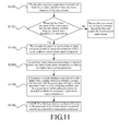
- An audio decoding method is shown in FIG. 11 , including steps as follows.
- Steps S1101-S1102 are similar to steps S1001-S1002 in the sixth embodiment, and thus no repetition is made here.
- step S 1103 when the noise signal corresponding to the received code stream switches from broadband to narrowband, the decoder decodes the received lower-band coding parameter by using the embedded CELP, to obtain a lower-band signal component s ⁇ LB post n .
- an artificial band extension technology may be used to extend the lower-band signal component s ⁇ LB post n , so as to obtain a higher-band coding parameter.
- a frequency-domain higher-band parameter time-varying weighting method may be used to perform a frequency-domain shaping on the higher-band coding parameter obtained through extension, and the shaped higher-band coding parameter is decoded to obtain a processed higher-band signal component.
- a frequency-domain weighting is performed on the higher-band coding parameter representing each sub-band with a different gain so that the signal band becomes wider slowly.
- the decoder receives an audio signal containing a broadband coding parameter (including an SID frame having a broadband core layer and a speech frame having a rate of 14kb/s or higher).
- the broadband-to-narrowband switching flag fad_out_flag is set to 0, and the transition frame counter fad_out_frame-count is set to 0.
- the decoder determines the occurrence of a switch from broadband to narrowband. Then, the broadband-to-narrowband switching flag fad_out_flag is set to 1.
- the buffer when a switch occurs, only broadband coding parameters of the noise frame are stored in the buffer (i.e., only TDBWE frequency-domain envelopes, without TDAC higher-band envelopes).
- the frames received after the switch will contain both noise frames and speech frames.
- the higher-band coding parameter in the duration of the solution of the embodiment may be reconstructed with the method of equation (1).
- the higher-band coding parameter of the noise has no TDAC higher-band envelope parameter as needed in the speech frame. Therefore, when the higher-band coding parameter is reconstructed for the received speech frame, the TDAC higher-band envelope is no longer reconstructed because the TDAC encoding algorithm is only an enhancement to the TDBWE encoding.
- the speech frames are decoded at a decreased rate of 14kb/s until the entire time-varying fadeout operation is completed.
- Each sub-band is weighted with a time-varying fadeout gain factor gain ( k,j ), in other words, F ⁇ env ( j ).
- gain ( k,j ) the time-varying fadeout spectral envelope may be obtained in the frequency-domain.
- the processed TDBWE frequency-domain envelope may be decoded with the TDBWE decoding algorithm, so as to obtain a time-varying fadeout higher-band signal component.
- a QMF filter bank may perform a synthesis filtering on the processed higher-band signal component and the decoded narrowband signal component s ⁇ LB post n , so as to reconstruct a time-varying fadeout signal.
- the decoder for example, the speech segment corresponding to the code stream received by the decoder switches from broadband to narrowband, the decoder still may receive a noise segment corresponding to the code stream after the switch, and the time-varying fadeout process uses a simplified version of the third method.
- An audio decoding method is shown in FIG. 12 , including steps as follows.
- Steps S1201-S1202 are similar to steps S1001-S1002 in the sixth embodiment, and thus no repetition is made here.
- the decoder may decode the received lower-band coding parameter with the embedded CELP, to obtain a lower-band signal component s ⁇ LB post n .
- step S1204 an artificial band extension technology is used to extend the lower-band signal component s ⁇ LB post n to obtain the higher-band coding parameter.
- the audio signal stored in the buffer may be of a type same as or different from the audio signal received after the switch, and the five cases as described in the sixth embodiment may be included. Detailed descriptions have been made to case (2) and case (3) in the above embodiments.
- the higher-band coding parameter may be reconstructed in accordance with the method of equation (1).
- the higher-band coding parameter of the noise frame has no TDAC higher-band envelope. Therefore, to reconstruct the coding parameter, the TDAC higher-band envelope will not be reconstructed, and only the frequency-domain envelope F ⁇ env ( J ) in the TDBWE algorithm is reconstructed.
- the TDAC encoding algorithm is only an enhancement to the TDBWE encoding. With the TDBWE frequency-domain envelope, it is sufficient to recover the higher-band signal component.
- the speech frames are decoded at a decreased rate of 14kb/s until the entire time-varying fadeout operation is completed.
- step S1205 a simplified method is used to perform a frequency-domain shaping on the higher-band coding parameter obtained through extension, and the shaped higher-band coding parameter is decoded to obtain a processed higher-band signal component.
- the reconstructed frequency-domain envelope F ⁇ env ( J ) divides the higher-band signal into J sub-bands within the frequency-domain.
- the broadband-to-narrowband switching flag fad_out_flag is 1 and the transition frame counter fad_out_frame_count meets the condition fad_out_frame_count ⁇ COUNT fad_out .
- the TDBWE decoding algorithm may be used for the processed TDBWE frequency-domain envelope, to obtain a time-varying fadeout higher-band signal component.
- LOW_LEVEL is the smallest possible value for the frequency-domain envelope in the quantization table.
- Level 2 quantization codebook is: Index Level 2 vector quantization codebook 0000 -2.9897100000f -2.9897100000f -1.9931400000f -0.9965700000f 0001 1.9931400000f 1.9931400000f 1.9931400000f 0010 0.0000000000f 0.0000000000f -1.9931400000f -1.9931400000f 0011 -0.9965700000f -0.9965700000f -0.9965700000f -1.9931400000f 0100 0.9965700000f 0.9965700000f 0.0000000000f -0.9965700000f 0101 0.9965700000f 0.9965700000f 0.9965700000f 0.0000000000f 0110 -1.9931400000f -1.9931400000f -2.9897100000f -2.9897100000f 0111 0.0000000000f 0.9965700000f 0.0000000000f 0.0000000000f 0.000000f 1000 -12.9554100000f -12.9554100
- F ⁇ env ( j ) l 1( j )+ l 2( j ), where l 1( j ) is a level 1 quantized vector, l 2( j ) is a level 2 quantized vector.
- a QMF filter bank performs a synthesis filtering on the processed higher-band signal component and the decoded reconstructed lower-band signal component, to reconstruct a time-varying fadeout signal.
- the invention applies to a switch from broadband to narrowband, as well as a switch from UWB to broadband.
- the higher-band signal component is decoded with the TDBWE or TDAC decoding algorithm. It is to be noted that the invention also applies to other broadband encoding algorithms in addition to the TDBWE and TDAC decoding algorithm. Additionally, there may be different methods for extending the higher-band signal component and the higher-band coding parameter after the switch, and no description is made here.
- an audio signal has a switch from broadband to narrowband
- a series of processes such as bandwidth detection, artificial band extension, time-varying fadeout process, and bandwidth synthesis, may be used to make the switch to have a smooth transition from a broadband signal to a narrowband signal so that a comfortable listening experience may be achieved.
- an audio decoding apparatus is shown in FIG. 12 , including an obtaining unit 10, an extending unit 20, a time-varying fadeout processing unit 30, and a synthesizing unit 40.
- the obtaining unit 10 is configured to obtain a lower-band signal component of an audio signal corresponding to a received code stream when the audio signal switches from a first bandwidth to a second bandwidth which is narrower than the first bandwidth, and transmit the lower-band signal component to the extending unit 20.
- the extending unit 20 is configured to extend the lower-band signal component to obtain higher-band information, and transmit the higher-band information obtained through extension to the time-varying fadeout processing unit 30.
- the time-varying fadeout processing unit 30 is configured to perform a time-varying fadeout process on the higher-band information obtained through extension to obtain a processed higher-band signal component, and transmit the processed higher-band signal component to the synthesizing unit 40.
- the synthesizing unit 40 is configured to synthesize the received processed higher-band signal component and the lower-band signal component obtained by the obtaining unit 10.
- the apparatus further includes a processing unit 50 and a detecting unit 60.
- the processing unit 50 is configured to determine the frame structure of the received code stream, and transmit the frame structure of the code stream to the detecting unit 60.
- the detecting unit 60 is configured to detect whether a switch from the first bandwidth to the second bandwidth occurs according to the frame structure of the code stream transmitted from the processing unit 50, and transmit the code stream to the obtaining unit 10 if the switch from the first bandwidth to the second bandwidth occurs.
- the extending unit 20 further includes at least one of a first extending sub-unit 21, a second extending sub-unit 22, and a third extending sub-unit 23.
- the first extending sub-unit 21 is configured to extend the lower-band signal component by using a coding parameter for the higher-band signal component received before the switch so as to obtain a higher-band coding parameter.
- the second extending sub-unit 22 is configured to extend the lower-band signal component by using a coding parameter for the higher-band signal component received before the switch so as to obtain a higher-band signal component.
- the third extending sub-unit 23 is configured to extend the lower-band signal component decoded from the current audio frame after the switch, so as to obtain the higher-band signal component.
- the time-varying fadeout processing unit 30 further includes at least one of a separate processing sub-unit 31 and a hybrid processing sub-unit 32.
- the separate processing sub-unit 31 is configured to perform a time-domain shaping and/or frequency-domain shaping on the higher-band signal component obtained through extension when the higher-band information obtained through extension is a higher-band signal component, and transmit the processed higher-band signal component to the synthesizing unit 40.
- the hybrid processing sub-unit 32 is configured to: when the higher-band information obtained through extension is a higher-band coding parameter, perform a frequency-domain shaping on the higher-band coding parameter obtained through extension; or when the higher-band information obtained through extension is a higher-band signal component, divide the higher-band signal component obtained through extension into sub-bands, perform a frequency-domain shaping on the coding parameter for each sub-band, and transmit the processed higher-band signal component to the synthesizing unit 50.
- the separate processing sub-unit 31 further includes at least one of a first sub-unit 311, a second sub-unit 312, a third sub-unit 313, and a fourth sub-unit 314.
- the first sub-unit 311 is configured to perform a time-domain shaping on the higher-band signal component obtained through extension by using a time-domain gain factor, and transmit the processed higher-band signal component to the synthesizing unit 40.
- the second sub-unit 312 is configured to perform a frequency-domain shaping on the higher-band signal component obtained through extension by using time-varying filtering, and transmit the processed higher-band signal component to the synthesizing unit 40.
- the third sub-unit 313 is configured to perform a time-domain shaping on the higher-band signal component obtained through extension by using a time-domain gain factor, perform a frequency-domain shaping on the time-domain shaped higher-band signal component by using time-varying filtering, and transmit the processed higher-band signal component to the synthesizing unit 40.
- the fourth sub-unit 314 is configured to perform a frequency-domain shaping on the higher-band signal component obtained through extension by using time-varying filtering, perform a time-domain shaping on the frequency-domain shaped higher-band signal component by using a time-domain gain factor, and transmit the processed higher-band signal component to the synthesizing unit 40.
- the hybrid processing sub-unit 32 further includes at least one of a fifth sub-unit 321 and a sixth sub-unit 322.
- the fifth sub-unit 321 is configured to: when the higher-band information obtained through extension is a higher-band coding parameter, perform a frequency-domain shaping on the higher-band coding parameter obtained through extension by using a frequency-domain higher-band parameter time-varying weighting method, so as to obtain a time-varying fadeout spectral envelope, obtain a higher-band signal component through decoding, and transmit the processed higher-band signal component to the synthesizing unit 40.
- the sixth sub-unit 322 is configured to: when the higher-band information obtained through extension is a higher-band signal component, divide the higher-band signal component obtained through extension into sub-bands; perform a frequency-domain higher-band parameter time-varying weighting on the coding parameter for each sub-band to obtain a time-varying fadeout spectral envelope; obtain a higher-band signal component through decoding; and transmit the processed higher-band signal component to the synthesizing unit 40.
- an audio signal when an audio signal has a switch from broadband to narrowband, a series of processes such as bandwidth detection, artificial band extension, time-varying fadeout process, and bandwidth synthesis, may be used to make the switch to have a smooth transition from a broadband signal to a narrowband signal so that a comfortable listening experience may be achieved.
- a series of processes such as bandwidth detection, artificial band extension, time-varying fadeout process, and bandwidth synthesis, may be used to make the switch to have a smooth transition from a broadband signal to a narrowband signal so that a comfortable listening experience may be achieved.
- the present invention may be implemented in hardware or by means of software and a necessary general-purpose hardware platform. Based on this understanding, the technical solution of the present invention may be embodied in a software product.
- the software product may be stored in a non-volatile storage media (which may be ROM/RAM, U disk, removable disk, etc.), including several instructions which cause a computer device (a PC, a server, a network device, or the like) to perform the methods according to the various embodiments of the present invention.
Landscapes
- Engineering & Computer Science (AREA)
- Quality & Reliability (AREA)
- Computational Linguistics (AREA)
- Signal Processing (AREA)
- Health & Medical Sciences (AREA)
- Audiology, Speech & Language Pathology (AREA)
- Human Computer Interaction (AREA)
- Physics & Mathematics (AREA)
- Acoustics & Sound (AREA)
- Multimedia (AREA)
- Compression, Expansion, Code Conversion, And Decoders (AREA)
Applications Claiming Priority (4)
| Application Number | Priority Date | Filing Date | Title |
|---|---|---|---|
| CN200710166745 | 2007-11-02 | ||
| CN200710187437 | 2007-11-23 | ||
| CN200810084725A CN100585699C (zh) | 2007-11-02 | 2008-03-14 | 一种音频解码的方法和装置 |
| EP08845741.1A EP2207166B1 (de) | 2007-11-02 | 2008-10-20 | Audiodekodierungsverfahren und -vorrichtung |
Related Parent Applications (1)
| Application Number | Title | Priority Date | Filing Date |
|---|---|---|---|
| EP08845741.1 Division | 2008-10-20 |
Publications (2)
| Publication Number | Publication Date |
|---|---|
| EP2629293A2 true EP2629293A2 (de) | 2013-08-21 |
| EP2629293A3 EP2629293A3 (de) | 2014-01-08 |
Family
ID=40590539
Family Applications (2)
| Application Number | Title | Priority Date | Filing Date |
|---|---|---|---|
| EP08845741.1A Active EP2207166B1 (de) | 2007-11-02 | 2008-10-20 | Audiodekodierungsverfahren und -vorrichtung |
| EP13168293.2A Withdrawn EP2629293A3 (de) | 2007-11-02 | 2008-10-20 | Verfahren und Vorrichtung zur Audiodecodierung |
Family Applications Before (1)
| Application Number | Title | Priority Date | Filing Date |
|---|---|---|---|
| EP08845741.1A Active EP2207166B1 (de) | 2007-11-02 | 2008-10-20 | Audiodekodierungsverfahren und -vorrichtung |
Country Status (7)
| Country | Link |
|---|---|
| US (1) | US8473301B2 (de) |
| EP (2) | EP2207166B1 (de) |
| JP (2) | JP5547081B2 (de) |
| KR (1) | KR101290622B1 (de) |
| BR (1) | BRPI0818927A2 (de) |
| RU (1) | RU2449386C2 (de) |
| WO (1) | WO2009056027A1 (de) |
Cited By (2)
| Publication number | Priority date | Publication date | Assignee | Title |
|---|---|---|---|---|
| EP2911152A1 (de) * | 2014-02-20 | 2015-08-26 | Samsung Electronics Co., Ltd | Graduelle Bandbreitenanpassung für codierte Audiosignale |
| RU2631155C1 (ru) * | 2014-03-24 | 2017-09-19 | Нтт Докомо, Инк. | Устройство аудиодекодирования, устройство аудиокодирования, способ аудиодекодирования, способ аудиокодирования, программа аудиодекодирования и программа аудиокодирования |
Families Citing this family (45)
| Publication number | Priority date | Publication date | Assignee | Title |
|---|---|---|---|---|
| FR2888699A1 (fr) * | 2005-07-13 | 2007-01-19 | France Telecom | Dispositif de codage/decodage hierachique |
| DE102008009720A1 (de) * | 2008-02-19 | 2009-08-20 | Siemens Enterprise Communications Gmbh & Co. Kg | Verfahren und Mittel zur Dekodierung von Hintergrundrauschinformationen |
| DE102008009719A1 (de) * | 2008-02-19 | 2009-08-20 | Siemens Enterprise Communications Gmbh & Co. Kg | Verfahren und Mittel zur Enkodierung von Hintergrundrauschinformationen |
| JP5754899B2 (ja) | 2009-10-07 | 2015-07-29 | ソニー株式会社 | 復号装置および方法、並びにプログラム |
| KR101423737B1 (ko) | 2010-01-21 | 2014-07-24 | 한국전자통신연구원 | 오디오 신호의 디코딩 방법 및 장치 |
| JP5850216B2 (ja) | 2010-04-13 | 2016-02-03 | ソニー株式会社 | 信号処理装置および方法、符号化装置および方法、復号装置および方法、並びにプログラム |
| JP5609737B2 (ja) | 2010-04-13 | 2014-10-22 | ソニー株式会社 | 信号処理装置および方法、符号化装置および方法、復号装置および方法、並びにプログラム |
| CN101964189B (zh) * | 2010-04-28 | 2012-08-08 | 华为技术有限公司 | 语音频信号切换方法及装置 |
| US8000968B1 (en) | 2011-04-26 | 2011-08-16 | Huawei Technologies Co., Ltd. | Method and apparatus for switching speech or audio signals |
| JP6075743B2 (ja) * | 2010-08-03 | 2017-02-08 | ソニー株式会社 | 信号処理装置および方法、並びにプログラム |
| US8762158B2 (en) * | 2010-08-06 | 2014-06-24 | Samsung Electronics Co., Ltd. | Decoding method and decoding apparatus therefor |
| CN102404072B (zh) * | 2010-09-08 | 2013-03-20 | 华为技术有限公司 | 一种信息比特发送方法、装置和系统 |
| JP5707842B2 (ja) | 2010-10-15 | 2015-04-30 | ソニー株式会社 | 符号化装置および方法、復号装置および方法、並びにプログラム |
| CN102800317B (zh) * | 2011-05-25 | 2014-09-17 | 华为技术有限公司 | 信号分类方法及设备、编解码方法及设备 |
| CN103187065B (zh) | 2011-12-30 | 2015-12-16 | 华为技术有限公司 | 音频数据的处理方法、装置和系统 |
| CN103295578B (zh) | 2012-03-01 | 2016-05-18 | 华为技术有限公司 | 一种语音频信号处理方法和装置 |
| CN103516440B (zh) | 2012-06-29 | 2015-07-08 | 华为技术有限公司 | 语音频信号处理方法和编码装置 |
| EP2951817B1 (de) | 2013-01-29 | 2018-12-05 | Fraunhofer-Gesellschaft zur Förderung der angewandten Forschung e.V. | Rauschfüllung in einer audiocodierung mit wahrnehmungsbezogener transformation |
| JP6305694B2 (ja) * | 2013-05-31 | 2018-04-04 | クラリオン株式会社 | 信号処理装置及び信号処理方法 |
| PT3011563T (pt) | 2013-06-21 | 2020-03-31 | Fraunhofer Ges Forschung | Descodificação de áudio com reconstrução de quadros corrompidos ou não recebidos usando tcx ltp |
| EP2830061A1 (de) | 2013-07-22 | 2015-01-28 | Fraunhofer Gesellschaft zur Förderung der angewandten Forschung e.V. | Vorrichtung und Verfahren zur Codierung und Decodierung eines codierten Audiosignals unter Verwendung von zeitlicher Rausch-/Patch-Formung |
| US9418671B2 (en) * | 2013-08-15 | 2016-08-16 | Huawei Technologies Co., Ltd. | Adaptive high-pass post-filter |
| JP6531649B2 (ja) | 2013-09-19 | 2019-06-19 | ソニー株式会社 | 符号化装置および方法、復号化装置および方法、並びにプログラム |
| US9293143B2 (en) | 2013-12-11 | 2016-03-22 | Qualcomm Incorporated | Bandwidth extension mode selection |
| KR20250012719A (ko) | 2013-12-27 | 2025-01-24 | 소니그룹주식회사 | 복호화 장치 및 방법, 및 프로그램 |
| CN104753653B (zh) * | 2013-12-31 | 2019-07-12 | 中兴通讯股份有限公司 | 一种解速率匹配的方法、装置和接收侧设备 |
| KR102318257B1 (ko) * | 2014-02-25 | 2021-10-28 | 한국전자통신연구원 | 레이어드 디비전 멀티플렉싱을 이용한 신호 멀티플렉싱 장치 및 신호 멀티플렉싱 방법 |
| US9542955B2 (en) * | 2014-03-31 | 2017-01-10 | Qualcomm Incorporated | High-band signal coding using multiple sub-bands |
| JP2016038513A (ja) * | 2014-08-08 | 2016-03-22 | 富士通株式会社 | 音声切替装置、音声切替方法及び音声切替用コンピュータプログラム |
| WO2016142002A1 (en) | 2015-03-09 | 2016-09-15 | Fraunhofer-Gesellschaft Zur Foerderung Der Angewandten Forschung E.V. | Audio encoder, audio decoder, method for encoding an audio signal and method for decoding an encoded audio signal |
| US10847170B2 (en) | 2015-06-18 | 2020-11-24 | Qualcomm Incorporated | Device and method for generating a high-band signal from non-linearly processed sub-ranges |
| US9837089B2 (en) * | 2015-06-18 | 2017-12-05 | Qualcomm Incorporated | High-band signal generation |
| EP3340664A1 (de) | 2015-09-15 | 2018-06-27 | Huawei Technologies Co., Ltd. | Verfahren und netzwerkvorrichtung zur herstellung eines drahtlosträgers |
| MX2019006535A (es) * | 2016-12-16 | 2019-08-21 | Ericsson Telefon Ab L M | Metodos, codificador y decodificador para manejar coeficientes de representacion de envolvente. |
| US10354668B2 (en) | 2017-03-22 | 2019-07-16 | Immersion Networks, Inc. | System and method for processing audio data |
| WO2018211050A1 (en) | 2017-05-18 | 2018-11-22 | Fraunhofer-Gesellschaft zur Förderung der angewandten Forschung e.V. | Managing network device |
| EP3483879A1 (de) | 2017-11-10 | 2019-05-15 | Fraunhofer-Gesellschaft zur Förderung der angewandten Forschung e.V. | Analyse-/synthese-fensterfunktion für modulierte geläppte transformation |
| EP3483886A1 (de) | 2017-11-10 | 2019-05-15 | Fraunhofer-Gesellschaft zur Förderung der angewandten Forschung e.V. | Auswahl einer grundfrequenz |
| EP3483878A1 (de) | 2017-11-10 | 2019-05-15 | Fraunhofer-Gesellschaft zur Förderung der angewandten Forschung e.V. | Audiodecoder mit auswahlfunktion für unterschiedliche verlustmaskierungswerkzeuge |
| EP3483883A1 (de) | 2017-11-10 | 2019-05-15 | Fraunhofer-Gesellschaft zur Förderung der angewandten Forschung e.V. | Audiokodierung und -dekodierung mit selektiver nachfilterung |
| EP3483884A1 (de) | 2017-11-10 | 2019-05-15 | Fraunhofer-Gesellschaft zur Förderung der angewandten Forschung e.V. | Signalfiltrierung |
| EP3483880A1 (de) | 2017-11-10 | 2019-05-15 | Fraunhofer-Gesellschaft zur Förderung der angewandten Forschung e.V. | Zeitliche rauschformung |
| WO2019091576A1 (en) | 2017-11-10 | 2019-05-16 | Fraunhofer-Gesellschaft zur Förderung der angewandten Forschung e.V. | Audio encoders, audio decoders, methods and computer programs adapting an encoding and decoding of least significant bits |
| EP3483882A1 (de) | 2017-11-10 | 2019-05-15 | Fraunhofer-Gesellschaft zur Förderung der angewandten Forschung e.V. | Steuerung der bandbreite in codierern und/oder decodierern |
| WO2025199960A1 (zh) * | 2024-03-29 | 2025-10-02 | 瑞声开泰声学科技(上海)有限公司 | 一种音频处理方法、电子设备及存储介质 |
Family Cites Families (34)
| Publication number | Priority date | Publication date | Assignee | Title |
|---|---|---|---|---|
| JPH08278800A (ja) * | 1995-04-05 | 1996-10-22 | Fujitsu Ltd | 音声通信システム |
| SE512719C2 (sv) * | 1997-06-10 | 2000-05-02 | Lars Gustaf Liljeryd | En metod och anordning för reduktion av dataflöde baserad på harmonisk bandbreddsexpansion |
| JP4132154B2 (ja) * | 1997-10-23 | 2008-08-13 | ソニー株式会社 | 音声合成方法及び装置、並びに帯域幅拡張方法及び装置 |
| JP4099879B2 (ja) * | 1998-10-26 | 2008-06-11 | ソニー株式会社 | 帯域幅拡張方法及び装置 |
| GB2357682B (en) * | 1999-12-23 | 2004-09-08 | Motorola Ltd | Audio circuit and method for wideband to narrowband transition in a communication device |
| US6704711B2 (en) * | 2000-01-28 | 2004-03-09 | Telefonaktiebolaget Lm Ericsson (Publ) | System and method for modifying speech signals |
| FI115329B (fi) | 2000-05-08 | 2005-04-15 | Nokia Corp | Menetelmä ja järjestely lähdesignaalin kaistanleveyden vaihtamiseksi tietoliikenneyhteydessä, jossa on valmiudet useisiin kaistanleveyksiin |
| SE0001926D0 (sv) * | 2000-05-23 | 2000-05-23 | Lars Liljeryd | Improved spectral translation/folding in the subband domain |
| US20020128839A1 (en) * | 2001-01-12 | 2002-09-12 | Ulf Lindgren | Speech bandwidth extension |
| US7113522B2 (en) | 2001-01-24 | 2006-09-26 | Qualcomm, Incorporated | Enhanced conversion of wideband signals to narrowband signals |
| SE522553C2 (sv) * | 2001-04-23 | 2004-02-17 | Ericsson Telefon Ab L M | Bandbreddsutsträckning av akustiska signaler |
| US7260541B2 (en) | 2001-07-13 | 2007-08-21 | Matsushita Electric Industrial Co., Ltd. | Audio signal decoding device and audio signal encoding device |
| US6988066B2 (en) * | 2001-10-04 | 2006-01-17 | At&T Corp. | Method of bandwidth extension for narrow-band speech |
| US6895375B2 (en) * | 2001-10-04 | 2005-05-17 | At&T Corp. | System for bandwidth extension of Narrow-band speech |
| CA2430923C (en) * | 2001-11-14 | 2012-01-03 | Matsushita Electric Industrial Co., Ltd. | Encoding device, decoding device, and system thereof |
| FR2849727B1 (fr) * | 2003-01-08 | 2005-03-18 | France Telecom | Procede de codage et de decodage audio a debit variable |
| FI119533B (fi) * | 2004-04-15 | 2008-12-15 | Nokia Corp | Audiosignaalien koodaus |
| EP1638083B1 (de) * | 2004-09-17 | 2009-04-22 | Harman Becker Automotive Systems GmbH | Bandbreitenerweiterung von bandbegrenzten Tonsignalen |
| CN100592389C (zh) * | 2008-01-18 | 2010-02-24 | 华为技术有限公司 | 合成滤波器状态更新方法及装置 |
| JP4821131B2 (ja) * | 2005-02-22 | 2011-11-24 | 沖電気工業株式会社 | 音声帯域拡張装置 |
| AU2006232357C1 (en) * | 2005-04-01 | 2010-11-25 | Qualcomm Incorporated | Method and apparatus for vector quantizing of a spectral envelope representation |
| US8249861B2 (en) * | 2005-04-20 | 2012-08-21 | Qnx Software Systems Limited | High frequency compression integration |
| JP4604864B2 (ja) * | 2005-06-14 | 2011-01-05 | 沖電気工業株式会社 | 帯域拡張装置及び不足帯域信号生成器 |
| WO2007000988A1 (ja) * | 2005-06-29 | 2007-01-04 | Matsushita Electric Industrial Co., Ltd. | スケーラブル復号装置および消失データ補間方法 |
| DE102005032724B4 (de) * | 2005-07-13 | 2009-10-08 | Siemens Ag | Verfahren und Vorrichtung zur künstlichen Erweiterung der Bandbreite von Sprachsignalen |
| ATE490454T1 (de) * | 2005-07-22 | 2010-12-15 | France Telecom | Verfahren zum umschalten der raten- und bandbreitenskalierbaren audiodecodierungsrate |
| US7734462B2 (en) * | 2005-09-02 | 2010-06-08 | Nortel Networks Limited | Method and apparatus for extending the bandwidth of a speech signal |
| EP1772855B1 (de) * | 2005-10-07 | 2013-09-18 | Nuance Communications, Inc. | Verfahren zur Erweiterung der Bandbreite eines Sprachsignals |
| US7546237B2 (en) * | 2005-12-23 | 2009-06-09 | Qnx Software Systems (Wavemakers), Inc. | Bandwidth extension of narrowband speech |
| JP2007271916A (ja) * | 2006-03-31 | 2007-10-18 | Yamaha Corp | 音声データ圧縮装置および伸張装置 |
| JP2007310298A (ja) * | 2006-05-22 | 2007-11-29 | Oki Electric Ind Co Ltd | 帯域外信号生成装置及び周波数帯域拡張装置 |
| CN2927247Y (zh) * | 2006-07-11 | 2007-07-25 | 中兴通讯股份有限公司 | 语音解码器 |
| KR101379263B1 (ko) * | 2007-01-12 | 2014-03-28 | 삼성전자주식회사 | 대역폭 확장 복호화 방법 및 장치 |
| KR101377702B1 (ko) * | 2008-12-11 | 2014-03-25 | 한국전자통신연구원 | 가변 대역 코덱 및 그 제어 방법 |
-
2008
- 2008-10-20 KR KR1020107011060A patent/KR101290622B1/ko active Active
- 2008-10-20 RU RU2010122326/08A patent/RU2449386C2/ru active
- 2008-10-20 BR BRPI0818927-7A patent/BRPI0818927A2/pt not_active IP Right Cessation
- 2008-10-20 EP EP08845741.1A patent/EP2207166B1/de active Active
- 2008-10-20 WO PCT/CN2008/072756 patent/WO2009056027A1/zh not_active Ceased
- 2008-10-20 JP JP2010532409A patent/JP5547081B2/ja active Active
- 2008-10-20 EP EP13168293.2A patent/EP2629293A3/de not_active Withdrawn
-
2010
- 2010-05-01 US US12/772,197 patent/US8473301B2/en active Active
-
2013
- 2013-07-05 JP JP2013141872A patent/JP2013235284A/ja active Pending
Non-Patent Citations (1)
| Title |
|---|
| None |
Cited By (4)
| Publication number | Priority date | Publication date | Assignee | Title |
|---|---|---|---|---|
| EP2911152A1 (de) * | 2014-02-20 | 2015-08-26 | Samsung Electronics Co., Ltd | Graduelle Bandbreitenanpassung für codierte Audiosignale |
| US9640192B2 (en) | 2014-02-20 | 2017-05-02 | Samsung Electronics Co., Ltd. | Electronic device and method of controlling electronic device |
| RU2631155C1 (ru) * | 2014-03-24 | 2017-09-19 | Нтт Докомо, Инк. | Устройство аудиодекодирования, устройство аудиокодирования, способ аудиодекодирования, способ аудиокодирования, программа аудиодекодирования и программа аудиокодирования |
| RU2654141C1 (ru) * | 2014-03-24 | 2018-05-16 | Нтт Докомо, Инк. | Устройство аудиодекодирования, устройство аудиокодирования, способ аудиодекодирования, способ аудиокодирования, программа аудиодекодирования и программа аудиокодирования |
Also Published As
| Publication number | Publication date |
|---|---|
| JP5547081B2 (ja) | 2014-07-09 |
| KR101290622B1 (ko) | 2013-07-29 |
| EP2207166B1 (de) | 2013-06-19 |
| EP2207166A4 (de) | 2010-11-24 |
| EP2207166A1 (de) | 2010-07-14 |
| RU2010122326A (ru) | 2011-12-10 |
| JP2011502287A (ja) | 2011-01-20 |
| KR20100085991A (ko) | 2010-07-29 |
| BRPI0818927A2 (pt) | 2015-06-16 |
| RU2449386C2 (ru) | 2012-04-27 |
| JP2013235284A (ja) | 2013-11-21 |
| EP2629293A3 (de) | 2014-01-08 |
| WO2009056027A1 (en) | 2009-05-07 |
| US20100228557A1 (en) | 2010-09-09 |
| US8473301B2 (en) | 2013-06-25 |
Similar Documents
| Publication | Publication Date | Title |
|---|---|---|
| EP2207166B1 (de) | Audiodekodierungsverfahren und -vorrichtung | |
| JP6728416B2 (ja) | パラメトリック・マルチチャネル・エンコードのための方法 | |
| US8577673B2 (en) | CELP post-processing for music signals | |
| EP1899962B1 (de) | Audio-codec-nachfilter | |
| EP2438592B1 (de) | Verfahren, vorrichtung und computerprogrammprodukt zur wiederherstellung eines gelöschten sprachrahmens | |
| RU2630390C2 (ru) | Устройство и способ для маскирования ошибок при стандартизированном кодировании речи и аудио с низкой задержкой (usac) | |
| KR101295729B1 (ko) | 비트 레이트규모 가변적 및 대역폭규모 가변적 오디오디코딩에서 비트 레이트 스위칭 방법 | |
| US8463603B2 (en) | Spectral envelope coding of energy attack signal | |
| CN1957398B (zh) | 在基于代数码激励线性预测/变换编码激励的音频压缩期间低频加重的方法和设备 | |
| KR102380487B1 (ko) | 오디오 신호 디코더에서의 개선된 주파수 대역 확장 | |
| CN101335002A (zh) | 一种音频解码的方法和装置 | |
| EP2202726B1 (de) | Verfahren und vorrichtung zur bewertung einer diskontinuierlichen übertragung | |
| JP2008537165A (ja) | 広帯域音声符号化のためのシステム、方法、及び装置 | |
| KR101891388B1 (ko) | 선형 예측 코딩에서 적응적 포먼트 선명화를 위한 시스템들, 방법들, 장치들, 및 컴퓨터 판독가능 매체들 | |
| CA2827272A1 (en) | Apparatus and method for encoding and decoding an audio signal using an aligned look-ahead portion | |
| US20110320193A1 (en) | Speech encoding device, speech decoding device, speech encoding method, and speech decoding method | |
| RU2574849C2 (ru) | Устройство и способ для кодирования и декодирования аудиосигнала с использованием выровненной части опережающего просмотра |
Legal Events
| Date | Code | Title | Description |
|---|---|---|---|
| PUAI | Public reference made under article 153(3) epc to a published international application that has entered the european phase |
Free format text: ORIGINAL CODE: 0009012 |
|
| 17P | Request for examination filed |
Effective date: 20130517 |
|
| AC | Divisional application: reference to earlier application |
Ref document number: 2207166 Country of ref document: EP Kind code of ref document: P |
|
| AK | Designated contracting states |
Kind code of ref document: A2 Designated state(s): AT BE BG CH CY CZ DE DK EE ES FI FR GB GR HR HU IE IS IT LI LT LU LV MC MT NL NO PL PT RO SE SI SK TR |
|
| PUAL | Search report despatched |
Free format text: ORIGINAL CODE: 0009013 |
|
| AK | Designated contracting states |
Kind code of ref document: A3 Designated state(s): AT BE BG CH CY CZ DE DK EE ES FI FR GB GR HR HU IE IS IT LI LT LU LV MC MT NL NO PL PT RO SE SI SK TR |
|
| RIC1 | Information provided on ipc code assigned before grant |
Ipc: G10L 19/24 20130101AFI20131205BHEP Ipc: G10L 21/038 20130101ALI20131205BHEP |
|
| STAA | Information on the status of an ep patent application or granted ep patent |
Free format text: STATUS: THE APPLICATION HAS BEEN WITHDRAWN |
|
| 18W | Application withdrawn |
Effective date: 20140616 |