EP2628165B1 - Method and apparatus for producing a stack of metal sheets - Google Patents
Method and apparatus for producing a stack of metal sheets Download PDFInfo
- Publication number
- EP2628165B1 EP2628165B1 EP11790780.8A EP11790780A EP2628165B1 EP 2628165 B1 EP2628165 B1 EP 2628165B1 EP 11790780 A EP11790780 A EP 11790780A EP 2628165 B1 EP2628165 B1 EP 2628165B1
- Authority
- EP
- European Patent Office
- Prior art keywords
- metal sheets
- sheets
- stack
- stop elements
- stacking table
- Prior art date
- Legal status (The legal status is an assumption and is not a legal conclusion. Google has not performed a legal analysis and makes no representation as to the accuracy of the status listed.)
- Not-in-force
Links
Images


Classifications
-
- B—PERFORMING OPERATIONS; TRANSPORTING
- B21—MECHANICAL METAL-WORKING WITHOUT ESSENTIALLY REMOVING MATERIAL; PUNCHING METAL
- B21D—WORKING OR PROCESSING OF SHEET METAL OR METAL TUBES, RODS OR PROFILES WITHOUT ESSENTIALLY REMOVING MATERIAL; PUNCHING METAL
- B21D43/00—Feeding, positioning or storing devices combined with, or arranged in, or specially adapted for use in connection with, apparatus for working or processing sheet metal, metal tubes or metal profiles; Associations therewith of cutting devices
- B21D43/20—Storage arrangements; Piling or unpiling
- B21D43/22—Devices for piling sheets
-
- B—PERFORMING OPERATIONS; TRANSPORTING
- B21—MECHANICAL METAL-WORKING WITHOUT ESSENTIALLY REMOVING MATERIAL; PUNCHING METAL
- B21D—WORKING OR PROCESSING OF SHEET METAL OR METAL TUBES, RODS OR PROFILES WITHOUT ESSENTIALLY REMOVING MATERIAL; PUNCHING METAL
- B21D28/00—Shaping by press-cutting; Perforating
- B21D28/02—Punching blanks or articles with or without obtaining scrap; Notching
-
- B—PERFORMING OPERATIONS; TRANSPORTING
- B65—CONVEYING; PACKING; STORING; HANDLING THIN OR FILAMENTARY MATERIAL
- B65H—HANDLING THIN OR FILAMENTARY MATERIAL, e.g. SHEETS, WEBS, CABLES
- B65H29/00—Delivering or advancing articles from machines; Advancing articles to or into piles
- B65H29/26—Delivering or advancing articles from machines; Advancing articles to or into piles by dropping the articles
- B65H29/30—Delivering or advancing articles from machines; Advancing articles to or into piles by dropping the articles from magnetic holders
-
- B—PERFORMING OPERATIONS; TRANSPORTING
- B65—CONVEYING; PACKING; STORING; HANDLING THIN OR FILAMENTARY MATERIAL
- B65H—HANDLING THIN OR FILAMENTARY MATERIAL, e.g. SHEETS, WEBS, CABLES
- B65H31/00—Pile receivers
- B65H31/04—Pile receivers with movable end support arranged to recede as pile accumulates
- B65H31/08—Pile receivers with movable end support arranged to recede as pile accumulates the articles being piled one above another
- B65H31/10—Pile receivers with movable end support arranged to recede as pile accumulates the articles being piled one above another and applied at the top of the pile
-
- B—PERFORMING OPERATIONS; TRANSPORTING
- B65—CONVEYING; PACKING; STORING; HANDLING THIN OR FILAMENTARY MATERIAL
- B65H—HANDLING THIN OR FILAMENTARY MATERIAL, e.g. SHEETS, WEBS, CABLES
- B65H31/00—Pile receivers
- B65H31/20—Pile receivers adjustable for different article sizes
-
- B—PERFORMING OPERATIONS; TRANSPORTING
- B65—CONVEYING; PACKING; STORING; HANDLING THIN OR FILAMENTARY MATERIAL
- B65H—HANDLING THIN OR FILAMENTARY MATERIAL, e.g. SHEETS, WEBS, CABLES
- B65H2301/00—Handling processes for sheets or webs
- B65H2301/40—Type of handling process
- B65H2301/42—Piling, depiling, handling piles
- B65H2301/421—Forming a pile
- B65H2301/4219—Forming a pile forming a pile in which articles are offset from each other, e.g. forming stepped pile
-
- B—PERFORMING OPERATIONS; TRANSPORTING
- B65—CONVEYING; PACKING; STORING; HANDLING THIN OR FILAMENTARY MATERIAL
- B65H—HANDLING THIN OR FILAMENTARY MATERIAL, e.g. SHEETS, WEBS, CABLES
- B65H2404/00—Parts for transporting or guiding the handled material
- B65H2404/70—Other elements in edge contact with handled material, e.g. registering, orientating, guiding devices
- B65H2404/72—Stops, gauge pins, e.g. stationary
- B65H2404/721—Stops, gauge pins, e.g. stationary adjustable
-
- B—PERFORMING OPERATIONS; TRANSPORTING
- B65—CONVEYING; PACKING; STORING; HANDLING THIN OR FILAMENTARY MATERIAL
- B65H—HANDLING THIN OR FILAMENTARY MATERIAL, e.g. SHEETS, WEBS, CABLES
- B65H2404/00—Parts for transporting or guiding the handled material
- B65H2404/70—Other elements in edge contact with handled material, e.g. registering, orientating, guiding devices
- B65H2404/74—Guiding means
- B65H2404/742—Guiding means for guiding transversely
-
- B—PERFORMING OPERATIONS; TRANSPORTING
- B65—CONVEYING; PACKING; STORING; HANDLING THIN OR FILAMENTARY MATERIAL
- B65H—HANDLING THIN OR FILAMENTARY MATERIAL, e.g. SHEETS, WEBS, CABLES
- B65H2701/00—Handled material; Storage means
- B65H2701/10—Handled articles or webs
- B65H2701/17—Nature of material
- B65H2701/173—Metal
-
- H—ELECTRICITY
- H01—ELECTRIC ELEMENTS
- H01F—MAGNETS; INDUCTANCES; TRANSFORMERS; SELECTION OF MATERIALS FOR THEIR MAGNETIC PROPERTIES
- H01F27/00—Details of transformers or inductances, in general
- H01F27/24—Magnetic cores
- H01F27/245—Magnetic cores made from sheets, e.g. grain-oriented
-
- H—ELECTRICITY
- H01—ELECTRIC ELEMENTS
- H01F—MAGNETS; INDUCTANCES; TRANSFORMERS; SELECTION OF MATERIALS FOR THEIR MAGNETIC PROPERTIES
- H01F41/00—Apparatus or processes specially adapted for manufacturing or assembling magnets, inductances or transformers; Apparatus or processes specially adapted for manufacturing materials characterised by their magnetic properties
- H01F41/02—Apparatus or processes specially adapted for manufacturing or assembling magnets, inductances or transformers; Apparatus or processes specially adapted for manufacturing materials characterised by their magnetic properties for manufacturing cores, coils, or magnets
- H01F41/0206—Manufacturing of magnetic cores by mechanical means
- H01F41/0233—Manufacturing of magnetic circuits made from sheets
Definitions
- the invention relates to a method for producing a stack of sheets, in particular sheets, which are free of guide holes and / or in particular of transformer sheets.
- the invention also relates to an apparatus for producing a stack of sheets, in particular sheets, which are free of guide holes and / or in particular of transformer sheets, wherein the apparatus comprises a stacking table and above the stacking table horizontally adjustable stop elements, which are designed and intended to be placed laterally sheets.
- the invention relates to a stack of sheets, in particular of sheets, which are free of guide holes, which is produced by a method according to the invention and / or with a device according to the invention.
- the prior art discloses methods and apparatus for producing a stack of plates, in particular a transformer core.
- a device for coating plates provided with guide holes for aligning each plate with a predetermined position.
- a horizontal base is provided to stack the plates.
- a conveyor sequentially advances the plates to a predetermined position above the horizontal base, the plates falling from the predetermined position on the conveyor to the horizontal base to laminate the plates.
- guide means with guide pins which move together with the falling plate to engage the corresponding guide holes.
- a device for holding stacked sheets, in particular transformer sheets is known.
- the sheets have a thread hole, so that they can be aligned by means of a threading bolt.
- a stacking device for transformer sheets having thread holes is also made DE 25 06 681 A1 known.
- the stacking device has height-fixed threading bolts, which engage in the thread holes of the transformer sheets during the stacking process.
- DE 21 63 700 a method for laying laid of individual sheets cores for transformers, inductors and the like, in which an already stored sheet itself serves as a stop for further sheets to be deposited.
- This embodiment has the disadvantage that no great accuracy with regard to the positioning of the individual sheets can be achieved. This is particularly because the edges of the sheets, which also serve as a stop for further sheets according to this method, usually have dimensional inaccuracies of a few tenths of a millimeter, as well as protruding burrs.
- DE 2551 497 discloses a device in which a core sheet is deposited on a stack. To remove the core sheet, a clamping caused by brake strips and guide rails is achieved. After releasing the clamping, the core sheet drops onto the stack with the fall of the core sheet passing through the funneling power.
- the further object is achieved by a device which is characterized in that the stop elements are formed and positioned such that they exclusively define a plurality of horizontal desired positions for a plurality of sheets to be deposited in the same horizontal plane.
- the stop elements are positioned such that each of the plurality of horizontal desired positions is determined without mechanical overdetermination.
- precise positioning is possible only when the setpoint position is reached by the stop elements is defined such that the sheet to be deposited can come to rest only in this one desired position.
- each of the plurality of horizontal desired positions is determined directly and exclusively by the stop elements.
- This embodiment has the particular advantage that one relies only on the stop elements whose position is known exactly, while on the use of other attacks, such as the use of the side edges or the corners of already deposited sheets can be completely dispensed as a stop. This achieves a particularly high precision.
- At least one sheet to be deposited is provided with a lateral recess, for example with a lateral notch and / or a lateral indentation, into which a stop element during depositing of the sheet at least partially intervenes.
- a lateral recess for example by a milling process-takes place with particularly great accuracy such that the recess has little, in particular none, imperfections, such as protruding burrs or measurement inaccuracies.
- the lateral recess for example the notch or the indentation
- the effort required to produce a precise notch or a precise indentation is very limited.
- a precise reference is thereby created on the sheet to be deposited, which allows a very accurate positioning of the sheet.
- a stop element has a projection-preferably rounded-which engages in a notch or indentation during the depositing process.
- the desired position is already determined by the engaging in the notch or indentation projection in the manner that the sheet is still free in the horizontal plane only in terms of its angular position.
- an additional stop is provided in an advantageous embodiment, which effectively prevents horizontal rotation of the sheet around the projection which engages in the notch. In this way, the target position of the sheet is defined clearly and without overdetermination.
- the stack is formed from layers, each having a plurality of juxtaposed and spaced apart sheets.
- the fact that the sheets are spaced apart in the storage position, is achieved in an advantageous manner that it does not come to inaccuracies, for example, because of abutting, protruding ridges on the individual sheet edges. It has been shown that a very good positioning accuracy can be achieved if the distance between adjacent plates is less than 0.5 mm, in particular less than 0.3 mm. In particular, it is advantageous if the spacing of adjacent sheets is in the range of 0.1 mm to 0.3 mm, in particular 0.2 mm.
- the method according to the invention it is possible to produce stacks which are formed from staggered layers and / or those within the layers have different sized and / or differently shaped sheets.
- the stop elements are positioned differently for the deposition of a new layer of sheets than in the previous layer of sheets.
- every possible shaping of sheet metal stacks is possible according to the invention.
- the vertical relative positioning takes place in that the stacking table is moved downwards in each case after the process of depositing, preferably by a distance corresponding to the thickness of the previously deposited sheets.
- Such a design has the particular advantage that the required horizontal adjustability and the required vertical adjustability are decoupled from each other in such a way that only the stacking table must be movable in the vertical direction, while the stop elements must be movable only in the horizontal direction.
- the complexity of the overall structure is drastically reduced. This particular because it can be dispensed with a vertical adjustability of the stop elements and a horizontal adjustability of the stacking table.
- the sheets are brought from above into the desired position.
- the relative positioning of the stacking table and / or the positioning of the stop elements and / or the deposition of the sheets takes place automatically and / or computer-controlled.
- the sheets to be deposited are cut out of a sheet metal material and / or punched and then immediately after the cutting or punching - spent without viteablegen - in their desired position.
- This design is particularly efficient both in terms of space requirements, as well as in terms of workload.
- On the one hand can be dispensed with an intermediate storage.
- Such an embodiment can be realized, for example, in the manner in which a cutting or punching system is controlled in such a way that - in terms of shape and size - the sheet is produced which is to be deposited next and / or which can be attached immediately to the row of sheets to be deposited is.
- a stack produced according to the inventive method and / or apparatus with a device according to the invention has the advantage that it can be free of guide holes.
- the fact that the individual sheets may have small lateral notches or indentations used for accurate positioning is generally irrelevant to the distribution of the magnetic field. This particular because the notches or indentations are small compared to the size of the sheet and in particular laterally - not like guide holes in the central region - are arranged.
- lateral notches or indentations has the further advantage that a stop element engaging there can be designed and shaped such that-unlike a guide pin in a guide hole-a very precise abutment position is defined.
- a stack of sheets which is produced according to the method according to the invention and / or with a device according to the invention can be constructed according to the invention in such a way that the stack is formed from layers which each have a plurality of sheets arranged next to one another and spaced from one another.
- the distance between adjacent plates is smaller than 0.5 mm, in particular less than 0.3 mm, in particular in the range of 0.1 mm to 0.3 mm, in particular about 0.2 mm.
- Fig. 1 shows a processing apparatus 1 with a device 2 for producing a stack of sheets and with a cutting and punching device 3 for cutting and punching to be deposited sheets.
- the cutting and punching device 3 is precisely made in each case in terms of size and shape, the sheet to be added next to the series of sheets to be deposited. After the production of a sheet to be deposited, this is transported to the device 2 for producing a stack of sheets with a transport device 4, which has magnetically operating transport gripper 5.
- the apparatus for producing a stack of sheets is shown only schematically in this figure.
- the device 2 for producing a stack of sheets has a height-adjustable stacking table 6, on which the sheets are deposited.
- Fig. 2 to 8 are individual steps of a method according to the invention for producing a stack of sheets which are free of guide holes, shown schematically.
- Fig. 2 shows a section of a device 2 according to the invention for producing a stack.
- the horizontally adjustable stop elements 7 are mounted at a fixed height.
- the stacking table is positioned vertically relative to the stop elements such that sheets deposited on the stacking table lie at the same vertical height at which the stop elements 7 are located.
- the stop elements 7 consist of small round projections which are attached to support rods 8.
- the vertical relative positioning of the stacking table relative to the horizontally adjustable stop elements is in the side view of Fig. 3 well illustrated. It can be clearly seen that the stop elements 7 are arranged directly above the stacking table 6.
- the horizontal positioning of the horizontally adjustable stop elements 7 is now carried out in such a manner that a plurality of horizontal desired positions for a plurality of sheets to be deposited are completely defined exclusively by the stop elements 7.
- the sheets to be deposited 11 are stored by the transport grippers 5 in the specified positions 10, the sheets are guided laterally when depositing the stop elements.
- the stacking table 6 is moved downwards by a distance corresponding to the sheet thickness of the deposited layer. Subsequently, the horizontally adjustable stop elements are positioned so that they completely set a plurality of horizontal target positions for several sheets to be deposited next layer. This is in Fig. 5 shown. Subsequently, the sheets of the next layer are deposited.
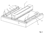
- Fig. 6 shows the thus growing stack 12 of stowed sheets 11. It is clearly seen that the stack has on its outer contour in the lower region of an increasing diameter staircase and in the upper part has a decreasing in diameter staircase. This situation is in Fig. 7 shown in perspective. After the stack 12 is completely made, the stacking table is moved down to expose the finished stack and transported away.
- Fig. 9 shows a detailed view of positioned sheets 11. It can be clearly seen that the sheets 11 are spaced from each other. In particular, one sheet 11 does not serve as a stop for another sheet 11. One of the sheets 11 has a precise notch 13 into which a stop element 7 rounded in its end region engages. There is another stop element 7 arranged on the opposite edge of this sheet, so that the target position of the sheet is completely defined by the stop elements 7.
Description
Die Erfindung betrifft ein Verfahren zum Herstellen eines Stapels von Blechen, insbesondere von Blechen, die frei von Führungslöchern sind und/oder insbesondere von Transformatorblechen.The invention relates to a method for producing a stack of sheets, in particular sheets, which are free of guide holes and / or in particular of transformer sheets.
Die Erfindung betrifft außerdem eine Vorrichtung zum Herstellen eines Stapels von Blechen, insbesondere von Blechen, die frei von Führungslöchern sind und/oder insbesondere von Transformatorblechen, wobei die Vorrichtung einen Stapeltisch und oberhalb des Stapeltisches horizontal verstellbare Anschlagelemente aufweist, die dazu ausgebildet und bestimmt sind, abzulegende Bleche seitlich zu führen.The invention also relates to an apparatus for producing a stack of sheets, in particular sheets, which are free of guide holes and / or in particular of transformer sheets, wherein the apparatus comprises a stacking table and above the stacking table horizontally adjustable stop elements, which are designed and intended to be placed laterally sheets.
Darüber hinaus betrifft die Erfindung einen Stapel von Blechen, insbesondere von Blechen, die frei von Führungslöchern sind, der nach einem erfindungsgemäßen Verfahren und/oder mit einer erfindungsgemäßen Vorrichtung hergestellt ist.Moreover, the invention relates to a stack of sheets, in particular of sheets, which are free of guide holes, which is produced by a method according to the invention and / or with a device according to the invention.
Aus dem Stand der Technik sind Verfahren und Vorrichtungen zum Herstellen eines Stapels von Platten, insbesondere eines Transformatorkernes, bekannt. Beispielsweise offenbart
Auch aus
Eine Stapelvorrichtung für Transformatorbleche, die Fädellöcher aufweisen, ist auch aus
Die Verfahren und Vorrichtungen der beschriebenen Art, die auf das Vorhandensein von Fädellöchern angewiesen sind, haben einerseits den Vorteil, dass eine Ausrichtung der Bleche einfach bewirkt werden kann. Andererseits haben diese Vorrichtungen und Verfahren jedoch den Nachteil, dass die aus solchen Blechen hergestellten Transformatorkerne nicht die gleiche Leistungsfähigkeit aufweisen, wie Transformatorkerne, die aus Blechen ohne Fädelloch bestehen. Dies ist insbesondere darauf zurückzuführen, dass die Ausbildung des magnetischen Feldes durch das Vorhandensein der Fädellöcher gestört wird.The methods and devices of the type described, which rely on the presence of Fädellöchern, on the one hand have the advantage that an alignment of the sheets can be easily effected. On the other hand, however, these devices and methods have the disadvantage that the transformer cores made of such sheets do not have the same performance as transformer cores consisting of sheets without thread hole. This is due in particular to the fact that the formation of the magnetic field is disturbed by the presence of the thread holes.
Zur Vermeidung des genannten Nachteils schlägt
Aus
Aus
Ferner ist aus
Es ist die Aufgabe der vorliegenden Erfindung, ein Verfahren zum Herstellen eines Stapels von Blechen anzugeben, das es ermöglicht, Bleche, die frei von Führungslöchern sind, zuverlässig und präzise zu stapeln, und das darüber hinaus hinsichtlich erzielbare Stapelformen flexibel einsetzbar ist.It is the object of the present invention to provide a method for producing a stack of sheets, which makes it possible to reliably and accurately stack sheets which are free of guide holes, and which is also flexible in terms of achievable stack shapes.
Die Aufgabe wird durch ein Verfahren zum Herstellen eines Stapels von Blechen gelöst, das durch folgende Schritte gekennzeichnet ist:
- a. vertikales Relativpositionieren eines Stapeltisches relativ zu horizontal verstellbaren Anschlagelementen, die oberhalb des Stapeltisches angeordnet sind,
- b. horizontales Positionieren der horizontal verstellbaren Anschlagselemente derart, dass für mehrere abzulegende Bleche jeweils ausschließlich durch die Anschlagselemente mehrere horizontale Sollpositionen in derselben horizontalen Ebene vollständig festgelegt sind und derart dass die Bleche beim Ablegen von den Anschlagelementen - vorzugsweise ausschließlich - seitlich geführt werden,
- c. sequentielles oder simultanes Ablegen der Bleche in den Sollpositionen und
- d. Wiederholen der Schritte a bis c mit weiteren Blechen solange, bis ein gewünschter Stapel, hergestellt ist.
- a. vertically relative positioning of a stacking table relative to horizontally adjustable stop elements, which are arranged above the stacking table,
- b. horizontal positioning of the horizontally adjustable stop elements such that for several sheets to be deposited in each case exclusively by the stop elements a plurality of horizontal desired positions in the same horizontal plane are completely set and such that the sheets when depositing the stop elements - preferably exclusively - are guided laterally,
- c. sequential or simultaneous depositing of the sheets in the nominal positions and
- d. Repeat steps a to c with further sheets until a desired stack is made.
Es ist die weitere Aufgabe der vorliegenden Erfindung, eine Vorrichtung zum Herstellen eines Stapels von Blechen, anzugeben, die in der Lage ist, die zu stapelnden Bleche effizient und positionsgenau zu positionieren und die darüber hinaus nicht auf Führungslöcher in den zu stapelnden Blechen angewiesen ist.It is the further object of the present invention to provide a device for producing a stack of sheets, which is able to position the sheets to be stacked efficiently and positionally and which, moreover, does not rely on guide holes in the sheets to be stacked.
Die weitere Aufgabe wird durch eine Vorrichtung gelöst, die dadurch gekennzeichnet ist, dass die Anschlagelemente derart ausgeformt und positionierbar sind, dass ausschließlich sie mehrere horizontale Sollpositionen für mehrere in derselben horizontalen Ebene abzulegende Bleche festlegen.The further object is achieved by a device which is characterized in that the stop elements are formed and positioned such that they exclusively define a plurality of horizontal desired positions for a plurality of sheets to be deposited in the same horizontal plane.
In erfindungsgemäßer Weise wurde erkannt, dass ein positionsgenaues Ablegen der Bleche auf einem Stapel insbesondere dann möglich ist, wenn zumindest weitgehend (vorzugsweise vollständig) darauf verzichtet wird, einzelne Bleche an den Kanten oder Ecken anderer Bleche auszurichten.In accordance with the invention, it has been recognized that positionally accurate depositing of the sheets on a stack is possible in particular if at least largely (preferably completely) it is dispensed with aligning individual sheets with the edges or corners of other sheets.
Bei einer besonders vorteilhaften Ausführung des erfindungsgemäßen Verfahrens ist vorgesehen, dass die Anschlagelemente derart positioniert werden, dass jede der mehreren horizontalen Sollpositionen ohne mechanische Überbestimmung festgelegt ist. Hierbei wurde erfindungsgemäß erkannt, dass ein genaues Positionieren ausschließlich dann möglich ist, wenn die Sollposition durch die Anschlagelemente derart definiert ist, dass das abzulegende Blech nur in dieser einen gewollten Position zu liegen kommen kann.In a particularly advantageous embodiment of the method according to the invention, it is provided that the stop elements are positioned such that each of the plurality of horizontal desired positions is determined without mechanical overdetermination. In this case, it has been recognized according to the invention that precise positioning is possible only when the setpoint position is reached by the stop elements is defined such that the sheet to be deposited can come to rest only in this one desired position.
Beispielsweise ist es nicht möglich, die Sollposition eines quadratischen Blechs mittels vier im Quadrat angeordneten Anschlagsschienen genau festzulegen. Denn um das Blech zwischen den Anschlagsschienen positionieren zu können muss ein Spiel vorhanden sein. Lässt man jedoch Spiel bei der Beispielanordnung zu und beabstandet die zueinander parallelen Anschlagsschienen in einem Abstand der größer als der Kantenabstand des Bleches ist, resultieren eine Vielzahl von Möglichkeiten, wie das Blech zwischen den Anschlagsschienen zu liegen kommen kann.For example, it is not possible to set the target position of a square sheet by means of four square arranged stop rails exactly. Because in order to position the sheet between the stop rails, a game must be present. If, however, clearance is allowed in the example arrangement and the mutually parallel stop rails are spaced apart by a distance greater than the edge distance of the sheet, a large number of possibilities arise as to how the metal sheet can come to lie between the stop rails.
Bei einer besonders vorteilhaften Ausführungsform ist vorgesehen, dass jede der mehreren horizontalen Sollpositionen unmittelbar und ausschließlich durch die Anschlagelemente festgelegt ist. Diese Ausführungsform hat insbesondere den Vorteil, dass man lediglich auf die Anschlagelemente zurückgreift, deren Position genau bekannt ist, während auf das Verwenden von anderen Anschlägen, wie beispielsweise auf das Verwenden der Seitenkanten oder der Ecken bereits abgelegter Bleche als Anschlag vollständig verzichtet werden kann. Hierdurch wird eine besonders große-Präzision erreicht.In a particularly advantageous embodiment, it is provided that each of the plurality of horizontal desired positions is determined directly and exclusively by the stop elements. This embodiment has the particular advantage that one relies only on the stop elements whose position is known exactly, while on the use of other attacks, such as the use of the side edges or the corners of already deposited sheets can be completely dispensed as a stop. This achieves a particularly high precision.
Bei einer besonderen Ausführungsform, mit der eine besonders große Positioniergenauigkeit erreicht werden kann, ist vorgesehen, dass zumindest ein abzulegendes Blech mit einer seitlichen Ausnehmung, beispielsweise mit einer seitlichen Kerbe und/oder einer seitlichen Einbuchtung, versehen wird, in die ein Anschlagelement während des Ablegens des Blechs zumindest teilweise eingreift. Hierbei kann insbesondere vorgesehen sein, dass die seitliche Ausnehmung - beispielsweise durch einen Fräsvorgang - mit besonders großer Genauigkeit derart erfolgt, dass die Ausnehmung wenig - insbesondere keine - Imperfektionen, wie überstehende Grate oder Messungenauigkeiten, aufweist.In a particular embodiment, with which a particularly high positioning accuracy can be achieved, it is provided that at least one sheet to be deposited is provided with a lateral recess, for example with a lateral notch and / or a lateral indentation, into which a stop element during depositing of the sheet at least partially intervenes. In this case, it can be provided, in particular, that the lateral recess-for example by a milling process-takes place with particularly great accuracy such that the recess has little, in particular none, imperfections, such as protruding burrs or measurement inaccuracies.
Es ist erfindungsgemäß auch möglich, die seitliche Ausnehmung auszustanzen. Da die seitliche Ausnehmung, beispielsweise die Kerbe bzw. die Einbuchtung, im Vergleich zur Gesamtgröße eines Blechs klein sein kann, hält sich der Aufwand zur Herstellung einer präzisen Kerbe bzw. einer präzisen Einbuchtung sehr in Grenzen. Im Gegenzug wird hierdurch jedoch am abzulegenden Blech eine präzise Referenz geschaffen, die ein äußerst positionsgenaues Ablegen des Blechs ermöglicht.It is also possible according to the invention to punch out the lateral recess. Since the lateral recess, for example the notch or the indentation, can be small in comparison to the overall size of a metal sheet, the effort required to produce a precise notch or a precise indentation is very limited. In return, however, a precise reference is thereby created on the sheet to be deposited, which allows a very accurate positioning of the sheet.
Hinsichtlich der Form der seitlichen Ausnehmung bestehen grundsätzlich keine Einschränkungen.With regard to the shape of the lateral recess, there are basically no restrictions.
Beispielsweise kann auch vorgesehen sein, dass ein Anschlagelement einen - vorzugsweise abgerundeten - Vorsprung aufweist, der in eine Kerbe oder Einbuchtung während des Ablegeprozesses eingreift. Die Sollposition ist durch den in die Kerbe oder Einbuchtung eingreifenden Vorsprung in der Weise bereits festgelegt, dass das Blech in der horizontalen Ebene lediglich hinsichtlich seiner Winkelstellung noch frei ist. Um diesen Freiheitsgrad einzugrenzen, ist bei einer vorteilhaften Ausführung ein weiterer Anschlag vorgesehen, der gewissermaßen ein horizontales Drehen des Blechs um den Vorsprung, der in die Kerbe eingreift, verhindert. Auf diese Weise ist die Sollposition des Blechs eindeutig und ohne Überbestimmung festgelegt.For example, it can also be provided that a stop element has a projection-preferably rounded-which engages in a notch or indentation during the depositing process. The desired position is already determined by the engaging in the notch or indentation projection in the manner that the sheet is still free in the horizontal plane only in terms of its angular position. In order to limit this degree of freedom, an additional stop is provided in an advantageous embodiment, which effectively prevents horizontal rotation of the sheet around the projection which engages in the notch. In this way, the target position of the sheet is defined clearly and without overdetermination.
Bei einer vorteilhaften Ausführung des erfindungsgemäßen Verfahrens ist vorgesehen, dass der Stapel aus Schichten gebildet wird, die jeweils mehrere nebeneinander angeordnete und voneinander beabstandete Bleche aufweisen. Dadurch, dass die Bleche in der Ablageposition voneinander beabstandet sind, ist in vorteilhafter Weise erreicht, dass es nicht zu Ungenauigkeiten, beispielsweise wegen aneinanderstoßender, überstehender Grate an den einzelnen Blechkanten kommt. Es hat sich gezeigt, dass eine sehr gute Positioniergenauigkeit erreicht werden kann, wenn der Abstand benachbarter Bleche kleiner als 0,5 mm, insbesondere kleiner als 0,3 mm ist. Insbesondere ist es von Vorteil, wenn der Abstand benachbarter Bleche im Bereich von 0,1 mm bis 0,3 mm, insbesondere bei 0,2 mm liegt.In an advantageous embodiment of the method according to the invention it is provided that the stack is formed from layers, each having a plurality of juxtaposed and spaced apart sheets. The fact that the sheets are spaced apart in the storage position, is achieved in an advantageous manner that it does not come to inaccuracies, for example, because of abutting, protruding ridges on the individual sheet edges. It has been shown that a very good positioning accuracy can be achieved if the distance between adjacent plates is less than 0.5 mm, in particular less than 0.3 mm. In particular, it is advantageous if the spacing of adjacent sheets is in the range of 0.1 mm to 0.3 mm, in particular 0.2 mm.
Mit dem erfindungsgemäßen Verfahren ist es möglich, Stapel herzustellen, die aus zueinander versetzten Schichten gebildet sind und/oder die innerhalb der Schichten unterschiedliche große und/oder unterschiedlich geformte Bleche aufweisen. Insbesondere um dies zu realisieren, kann in erfindungsgemäßer Weise vorgesehen sein, dass die Anschlagelemente für das Ablegen einer neuen Schicht von Blechen anders positioniert werden als bei der vorhergehenden Schicht von Blechen. Insoweit ist jede denkbare Ausformung von Blechstapeln erfindungsgemäß ermöglicht. Insbesondere ist es ermöglicht Blechstapel herzustellen, die in einer untersten Schicht und einer obersten Schicht schmaler, sind als in einer Mittelschicht. Auch Abtreppungen sind weitestgehend uneingeschränkt möglich.With the method according to the invention it is possible to produce stacks which are formed from staggered layers and / or those within the layers have different sized and / or differently shaped sheets. In particular in order to realize this, it can be provided according to the invention that the stop elements are positioned differently for the deposition of a new layer of sheets than in the previous layer of sheets. In that regard, every possible shaping of sheet metal stacks is possible according to the invention. In particular, it is possible to produce sheet stacks which are narrower in a bottom layer and a top layer than in a middle layer. Also Abtreppungen are largely unrestricted possible.
Bei einer vorteilhaften Ausführung der Erfindung ist vorgesehen, dass das vertikale Relativpositionieren dadurch erfolgt, dass der Stapeltisch jeweils nach dem Vorgang des Ablegens, vorzugsweise um eine Strecke, die der Dicke der zuvor abgelegten Bleche entspricht, nach unten verfahren wird. Eine solche Ausführung hat den besonderen Vorteil, dass die erforderliche horizontale Einstellbarkeit und die erforderliche vertikale Einstellbarkeit voneinander in der Weise entkoppelt sind, dass ausschließlich der Stapeltisch in vertikaler Richtung verfahrbar sein muss, während die Anschlagelemente lediglich in horizontaler Richtung beweglich sein müssen. Hierdurch ist die Komplexität des Gesamtaufbaus in drastischer Weise reduziert. Dies insbesondere deshalb, weil auf eine Vertikalverstellbarkeit der Anschlagelemente und auf eine Horizontalverstellbarkeit des Stapeltisches verzichtet werden kann.In an advantageous embodiment of the invention it is provided that the vertical relative positioning takes place in that the stacking table is moved downwards in each case after the process of depositing, preferably by a distance corresponding to the thickness of the previously deposited sheets. Such a design has the particular advantage that the required horizontal adjustability and the required vertical adjustability are decoupled from each other in such a way that only the stacking table must be movable in the vertical direction, while the stop elements must be movable only in the horizontal direction. As a result, the complexity of the overall structure is drastically reduced. This particular because it can be dispensed with a vertical adjustability of the stop elements and a horizontal adjustability of the stacking table.
Allerdings ist es erfindungsgemäß, insbesondere für die Herstellung besonderes schwerer Blechstapel, auch möglich, einen in der Höhe festen Stapeltisch zu verwenden und zur vertikalen Relativpositionierung die Anschlagelemente vertikal zu verfahren.However, according to the invention, in particular for the production of special heavy sheet stacks, it is also possible to use a stacking table fixed in height and to move the stop elements vertically for vertical relative positioning.
Gemäß einer vorteilhaften Ausführung der Erfindung ist vorgesehen, dass die Bleche von oben in die Sollposition gebracht werden.According to an advantageous embodiment of the invention it is provided that the sheets are brought from above into the desired position.
Insbesondere kann erfindungsgemäß vorgesehen sein, dass das Relativpositionieren des Stapeltisches und/oder das Positionieren der Anschlagelemente und/oder das Ablegen der Bleche automatisch und/oder computergesteuert erfolgt.In particular, it can be provided according to the invention that the relative positioning of the stacking table and / or the positioning of the stop elements and / or the deposition of the sheets takes place automatically and / or computer-controlled.
Bei einer ganz besonders vorteilhaften Ausführung des erfindungsgemäßen Verfahrens werden die abzulegenden Bleche aus einem Rohblechmaterial ausgeschnitten und/oder ausgestanzt und dann unmittelbar nach dem Ausschneiden bzw. Ausstanzen - ohne Zwischenablegen - in ihre Sollposition verbracht. Diese Ausführung ist sowohl hinsichtlich des Raumbedarfs, als auch hinsichtlich des Arbeitsaufwandes besonders effizient. Zum einen kann auf ein Zwischenlager verzichtet werden. Darüber hinaus entfällt der Arbeitsschritt des Umlagerns. Eine solche Ausführung ist in der Weise beispielsweise realisierbar, als eine Schneid- bzw. Stanzanlage derart gesteuert wird, dass jeweils - hinsichtlich Form und Größe - das Blech hergestellt wird, das als Nächstes abzulegen ist und/oder das sofort der Reihe der abzulegenden Blechen anfügbar ist.In a particularly advantageous embodiment of the method according to the invention, the sheets to be deposited are cut out of a sheet metal material and / or punched and then immediately after the cutting or punching - spent without Zwischenablegen - in their desired position. This design is particularly efficient both in terms of space requirements, as well as in terms of workload. On the one hand can be dispensed with an intermediate storage. In addition, eliminates the task of repositioning. Such an embodiment can be realized, for example, in the manner in which a cutting or punching system is controlled in such a way that - in terms of shape and size - the sheet is produced which is to be deposited next and / or which can be attached immediately to the row of sheets to be deposited is.
Ein gemäß dem erfindungsgemäßen Verfahren und/oder mit einer erfindungsgemäßen Vorrichtung hergestellter Stapel von Blechen hat den Vorteil, dass dieser frei von Führungslöchern sein kann. Die Tatsache, dass die einzelnen Bleche möglicherweise kleine seitliche Kerben oder Einbuchtungen aufweisen, die zur genauen Positionierung benutzt wurden, spielt hinsichtlich der Verteilung des Magnetfeldes in aller Regel keine Rolle. Dies insbesondere auch deshalb, weil die Kerben bzw. Einbuchtungen im Vergleich zur Größe des Bleches klein sind und insbesondere seitlich - nicht wie Führungslöcher im Mittelbereich - angeordnet sind.A stack produced according to the inventive method and / or apparatus with a device according to the invention has the advantage that it can be free of guide holes. The fact that the individual sheets may have small lateral notches or indentations used for accurate positioning is generally irrelevant to the distribution of the magnetic field. This particular because the notches or indentations are small compared to the size of the sheet and in particular laterally - not like guide holes in the central region - are arranged.
Die Verwendung von seitlichen Kerben bzw. Einbuchtungen hat den weiteren Vorteil, dass ein dort eingreifendes Anschlagelement derart ausgebildet und ausgeformt sein kann, sodass - anders als bei einem Führungsdorn in einem Führungsloch - eine sehr genaue Anlageposition definiert ist.The use of lateral notches or indentations has the further advantage that a stop element engaging there can be designed and shaped such that-unlike a guide pin in a guide hole-a very precise abutment position is defined.
Ein Stapel von Blechen der gemäß dem erfindungsgemäßen Verfahren und/oder mit einer erfindungsgemäßen Vorrichtung hergestellt ist, kann in erfindungsgemäßer Weise derart aufgebaut sein, dass der Stapel aus Schichten gebildet ist, die jeweils mehrere nebeneinander angeordnete und voneinander beabstandete Bleche aufweist.A stack of sheets which is produced according to the method according to the invention and / or with a device according to the invention can be constructed according to the invention in such a way that the stack is formed from layers which each have a plurality of sheets arranged next to one another and spaced from one another.
Insbesondere kann vorgesehen sein, dass der Abstand benachbarter Bleche kleiner als 0,5 mm ist, insbesondere kleiner als 0,3 mm ist, insbesondere im Bereich von 0,1 mm bis 0,3 mm liegt, insbesondere ca. 0,2 mm beträgt.In particular, it can be provided that the distance between adjacent plates is smaller than 0.5 mm, in particular less than 0.3 mm, in particular in the range of 0.1 mm to 0.3 mm, in particular about 0.2 mm.
Weitere Ziele, Vorteile, Merkmale und Anwendungsmöglichkeiten der vorliegenden Erfindung ergeben sich aus der nachfolgenden Beschreibung eines Ausführungsbeispieles anhand der Zeichnung. Dabei bilden alle beschriebenen und/oder bildlich dargestellten Merkmale für sich oder in beliebiger sinnvoller Kombination den Gegenstand der vorliegenden Erfindung, auch unabhängig von ihrer Zusammenfassung in den Ansprüchen oder deren Rückbeziehung.Other objects, advantages, features and applications of the present invention will become apparent from the following description of an embodiment with reference to the drawings. All described and / or illustrated features alone or in any meaningful combination form the subject matter of the present invention, also independent of their summary in the claims or their dependency.
Es zeigen
- Fig. 1
- eine erfindungsgemäße Vorrichtung mit einer Schneid- und Stanzvorrichtung zum Ausschneiden und Ausstanzen von abzulegenden Blechen,
- Fig. 2 bis Fig. 8
- einzelne Schritte eines erfindungsgemäßen Verfahrens und
- Fig. 9
- eine Detailansicht positionsgenau abgelegter Einzelbleche.
- Fig. 1
- a device according to the invention with a cutting and punching device for cutting and punching to be deposited sheets,
- Fig. 2 to Fig. 8
- individual steps of a method according to the invention and
- Fig. 9
- a detailed view of exactly positioned individual sheets.
Die Vorrichtung 2 zum Herstellen eines Stapels von Blechen weist einen höhenverstellbaren Stapeltisch 6 auf, auf dem die Bleche abgelegt werden. Darüber hinaus weist die Vorrichtung 2 zum Herstellen eines Stapels von Blechen horizontale Anschlagelemente 7 auf, die dazu ausgebildet und bestimmt sind, die Bleche beim Ablegen seitlich zu führen, wobei die Anschlagelemente derart ausgeformt und positionierbar sind, dass ausschließlich sie mehrere horizontale Sollpositionen für mehrere abzulegende Bleche festlegen.The
In den
In einem weiteren Schritt erfolgt nun das Horizontalpositionieren der horizontal verstellbaren Anschlagelemente 7 derart, dass mehrere horizontale Sollpositionen für mehrere abzulegende Bleche jeweils ausschließlich durch die Anschlagelemente 7 vollständig festgelegt sind. In einem weiteren Schritt, der exemplarisch in
Nach dem Ablegen einer vollständigen Schicht von Blechen wird der Stapeltisch 6 um eine Strecke, die der Blechdicke der abgelegten Schicht entspricht, nach unten verfahren. Anschließend werden die horizontal verstellbaren Anschlagelemente derart positioniert, dass sie mehrere horizontale Sollpositionen für mehrere abzulegende Bleche der nächsten Schicht vollständig festlegen. Dies ist in
- 11
- Verarbeitungsvorrichtungprocessing device
- 22
- Vorrichtung zum Herstellen eines Stapels von BlechenApparatus for producing a stack of sheets
- 33
- Schneid- und StanzvorrichtungCutting and punching device
- 44
- Transportvorrichtungtransport device
- 55
- Transportgreifertransport claw
- 66
- Stapeltischstacking table
- 77
- Horizontal verstellbare AnschlagelementeHorizontally adjustable stop elements
- 88th
- HaltestangenHandrails
- 1010
- Sollpositionentarget positions
- 1111
- Blechesheets
- 1212
- Stapelstack
- 1313
- Kerbescore
Claims (16)
- Method for producing a stack (12) of metal sheets (11), in particular metal sheets (11) which are free of guide holes and/or in particular transformer sheets, characterized by the following steps:a. vertically positioning a stacking table (6) relative to horizontally adjustable stop elements (7), which are arranged above the stacking table (6),b. horizontally positioning the horizontally adjustable stop elements (7) such that, for a plurality of metal sheets (11) which are to be set down, in each case exclusively the stop elements (7) fully define a plurality of horizontal desired positions (10) in the same horizontal plane, and such that the metal sheets (11), when being set down, are guided - preferably exclusively - laterally by the stop elements (7),c. sequential or simultaneous setting down of the metal sheets (11) in the desired positions (10), andd. repeating steps a to c with further metal sheets (11) until a desired stack (12) has been produced.
- Method according to Claim 1, characterized in that the stop elements (7) are positioned such that each of the plurality of horizontal desired positions (10) is defined without mechanical redundancy, and/or in that the stop elements (7) are positioned such that each of the plurality of horizontal desired positions (10) is defined directly and exclusively by the stop elements (7).
- Method according to either of Claims 1 and 2, characterized in that at least one metal sheet (11) which is to be set down is provided with a lateral recess, for example with a lateral notch (13) and/or indent, in which a stop element (7) engages, at least in part, during the operation of setting down the metal sheet (11).
- Method according to one of Claims 1 to 3, characterized in that the stack (12) is formed from layers which each have a plurality of spaced-apart metal sheets (11) arranged one beside the other, wherein the distance between adjacent metal sheets is smaller than 0.5 mm, in particular smaller than 0.3 mm, in particular ranges from 0.1 mm to 0.3 mm, in particular is approximately 0.2 mm.
- Method according to one of Claims 1 to 4, characterized in that the stack (12) is formed from layers which are offset in relation to one another, and/or in that the stack (12) is formed from layers which each have metal sheets (11) of different sizes, and/or in that the stack (12) is formed from layers which each have metal sheets (11) of different shapes.
- Method according to one of Claims 1 to 5, characterized in that the operation involving vertical relative positioning takes place in that the stacking table (6), in each case following the setting-down operation, is displaced downwards - preferably by a distance which corresponds to the thickness of the previously set-down metal sheets (11).
- Method according to one of Claims 1 to 6, characterized in that the metal sheets (11) are moved into the desired position (10) from above.
- Method according to one of Claims 1 to 7, characterized in that the operations involving relative positioning and/or positioning and/or setting down take place automatically and/or in a computer-controlled manner.
- Method according to one of Claims 1 to 8, characterized in that the metal sheets (11) which are to be set down are cut and/or punched out of a sheet-material blank, and in that the metal sheets (11) are moved into their desired positions (10) immediately following the cutting-out or punching-out operation, without any interim storage.
- Apparatus for producing a stack (12) of metal sheets (11), in particular metal sheets (11) which are free of guide holes and/or in particular transformer sheets, wherein the apparatus has a stacking table (6) and stop elements (7) which can be adjusted horizontally above the stacking table (6) and are designed, and intended, to provide lateral guidance for metal sheets (11) which are to be set down, characterized in that the stop elements (7) are formed, and can be positioned, such that exclusively the stop elements define a plurality of horizontal desired positions (10) for a plurality of metal sheets (11) which are to be set down in the same horizontal plane.
- Apparatus according to Claim 10, characterized in that the stop elements (7) can be positioned such that each of the plurality of desired positions (10) is defined without mechanical redundancy, and/or in that the stop elements (7) can be positioned such that each of the plurality of horizontal desired positions (10) is defined directly and exclusively by the stop elements (7).
- Apparatus according to either of Claims 10 and 11, characterized in that at least one stop element (7) has a protrusion which is designed, and intended, to engage in a lateral recess, for example a lateral notch (13) and/or a lateral indent, of a metal sheet (11) which is to be set down.
- Apparatus according to one of Claims 10 to 12, characterized in that the stacking table (6) is height-adjustable, and/or in that the stacking table (6) is height-adjustable in such a manner that, once the metal sheets (11) have been set down in their horizontal desired positions (10), the stacking table can be moved downwards by a distance which corresponds to the thickness of the set-down metal sheets (11).
- Processing apparatus (1) having an apparatus according to one of Claims 10 to 13 and having a cutting and/or punching apparatus (3) for cutting and/or punching out from a raw material metal sheets (11) which are to be set down.
- Stack of metal sheets, in particular of metal sheets (11) which are free of guide holes, which is produced by a method according to one of Claims 1 to 9 and/or produced using an apparatus according to one of Claims 10 to 14 and in the case of which at least one set-down metal sheet (11) is provided with a lateral recess, in which the stop element engages during the operation of setting down the metal sheet.
- Stack according to Claim 15, characterized in that the stack (12) is formed from layers which each have a plurality of spaced-apart metal sheets (11) arranged one beside the other, wherein the distance between adjacent metal sheets (11) is smaller than 0.5 mm, in particular smaller than 0.3 mm, in particular ranges from 0.1 mm to 0.3 mm, in particular is approximately 0.2 mm.
Applications Claiming Priority (2)
| Application Number | Priority Date | Filing Date | Title |
|---|---|---|---|
| DE201010061022 DE102010061022B3 (en) | 2010-12-03 | 2010-12-03 | Method and device for producing a stack of sheets |
| PCT/EP2011/071421 WO2012072699A2 (en) | 2010-12-03 | 2011-11-30 | Method and apparatus for producing a stack of metal sheets |
Publications (2)
| Publication Number | Publication Date |
|---|---|
| EP2628165A2 EP2628165A2 (en) | 2013-08-21 |
| EP2628165B1 true EP2628165B1 (en) | 2014-06-11 |
Family
ID=45092357
Family Applications (1)
| Application Number | Title | Priority Date | Filing Date |
|---|---|---|---|
| EP11790780.8A Not-in-force EP2628165B1 (en) | 2010-12-03 | 2011-11-30 | Method and apparatus for producing a stack of metal sheets |
Country Status (3)
| Country | Link |
|---|---|
| EP (1) | EP2628165B1 (en) |
| DE (1) | DE102010061022B3 (en) |
| WO (1) | WO2012072699A2 (en) |
Families Citing this family (5)
| Publication number | Priority date | Publication date | Assignee | Title |
|---|---|---|---|---|
| DE102017202749A1 (en) | 2017-02-21 | 2018-08-23 | Kba-Metalprint Gmbh | Method and device for stacking flat sheets of material and a printing and / or varnishing machine |
| US11161167B2 (en) | 2017-02-21 | 2021-11-02 | Koenig & Bauer Metalprint Gmbh | Method and device for stacking flat material sheets, and device and sheet metal printing machine for processing and/or treating material sheets in the form of metal sheets |
| EP3665711B1 (en) * | 2017-08-10 | 2022-03-30 | Heinrich Georg GmbH Maschinenfabrik | Apparatus for and method of manufacturing transformer cores |
| CN110394749A (en) * | 2019-07-30 | 2019-11-01 | 南通思瑞机器制造有限公司 | Transformer silicon steel sheet closed assembly accurate positioning device |
| CN114582619B (en) * | 2022-03-25 | 2023-11-14 | 无锡普天铁心股份有限公司 | Pre-stacking device for iron core column of transformer |
Family Cites Families (9)
| Publication number | Priority date | Publication date | Assignee | Title |
|---|---|---|---|---|
| DE1081831B (en) * | 1958-08-04 | 1960-05-12 | Moeller & Neumann Gmbh | Device for stacking sheets staggered in groups |
| DE2163700C3 (en) | 1971-12-22 | 1979-03-15 | Transformatoren Union Ag, 7000 Stuttgart | Method and apparatus for the automatic layering of individual sheets for the lower yoke and the legs of multi-leg cores for transformers, inductors, and the like |
| DE2506681A1 (en) | 1975-02-17 | 1976-08-26 | Heinrich Georg Maschinenfabrik | STACKING DEVICE FOR TRANSFORMER SHEETS |
| DE2530309C3 (en) * | 1975-07-08 | 1979-01-25 | Waldemar Von 5340 Bad Honnef Lewin | Device for carrying out a program-controlled manufacturing process for laminated cores for transformers |
| DE2537410C2 (en) * | 1975-08-22 | 1983-08-11 | Brown, Boveri & Cie Ag, 6800 Mannheim | Device for stacking individual sheets to form a sheet package |
| DE2551497C3 (en) * | 1975-11-17 | 1982-02-11 | Heinrich Georg GmbH Maschinenfabrik, 5910 Kreuztal | Device for stacking transformer core sheets at the same edge |
| DE3028605C2 (en) | 1980-07-28 | 1983-10-27 | Transformatoren Union Ag, 7000 Stuttgart | Device for layering cores for transformers and reactors |
| JP2903925B2 (en) | 1992-11-16 | 1999-06-14 | 富士電機株式会社 | Plate stacking device |
| DE10332018B3 (en) | 2003-07-15 | 2005-01-13 | Heinrich Georg Gmbh Maschinenfabrik | Holding apparatus for transformer laminations, has bolt which engages into hole in guide cartridge inserted into hole in pallet |
-
2010
- 2010-12-03 DE DE201010061022 patent/DE102010061022B3/en not_active Withdrawn - After Issue
-
2011
- 2011-11-30 WO PCT/EP2011/071421 patent/WO2012072699A2/en active Application Filing
- 2011-11-30 EP EP11790780.8A patent/EP2628165B1/en not_active Not-in-force
Also Published As
| Publication number | Publication date |
|---|---|
| WO2012072699A2 (en) | 2012-06-07 |
| EP2628165A2 (en) | 2013-08-21 |
| DE102010061022B3 (en) | 2012-03-01 |
| WO2012072699A3 (en) | 2012-08-16 |
Similar Documents
| Publication | Publication Date | Title |
|---|---|---|
| EP3102515B1 (en) | Method and installation for the deposition of profiled rods | |
| EP2628165B1 (en) | Method and apparatus for producing a stack of metal sheets | |
| EP2441547B1 (en) | Method of separating finished parts and sheet chutes after laser cutting a sheet panel | |
| EP2159173A1 (en) | Transport device and method for controlled transport of items | |
| EP2605987B1 (en) | Non-stop device | |
| EP2172109B1 (en) | Method for creating dough blanks with an at least mainly triangular and equal-sided basic shape from a dough strip and corresponding device | |
| EP0553724A1 (en) | Method and device for the production of defined piles of folded or unfolded sheets or sheet-like material | |
| DE2151102B2 (en) | Structure and process for its manufacture | |
| DE3625841A1 (en) | STACKING DEVICE FOR, IN PARTICULAR MANUFACTURED IN A THERMOFORMING MACHINE, PLASTIC DRAWING PARTS | |
| DE3716666A1 (en) | Panel-dividing installation with a ripsaw and a cross-cut saw | |
| DE102014001779A1 (en) | Device for storing filament bobbins | |
| EP1950159B1 (en) | Method and device for manufacturing a stacked arrangement of flat objects | |
| DE102012009259B4 (en) | Transformer core stacking plant for connection to a transformer plate cutting and stamping plant and method for operating the transformer core stacking plant | |
| EP2316611B1 (en) | Loading device for material rods | |
| DE2744061C2 (en) | ||
| DE3302046A1 (en) | Method for stacking or unstacking elongated material and stacking and/or unstacking device | |
| DE102009007987A1 (en) | Sheets i.e. packing sheets, stacking device, has conveying device for transporting sheets to be stacked, and carriage arranged below conveying device such that sheets arranged in displacement position are stacked at carriage | |
| EP0414061B1 (en) | Device for drawing a metal rod out of a rod bundle | |
| EP2009652B1 (en) | Method of manufacturing transformer cores | |
| AT398746B (en) | DEVICE FOR COMPILING STAPLE PICTURES RECOVERED ON A PLATE DISPENSING SYSTEM BY LENGTH AND CROSS-SECTIONS FROM PLATE-SHAPED WORKPIECES | |
| DE4209952C2 (en) | Establishment of color dividing systems | |
| DE3712657C2 (en) | ||
| DE2009138C3 (en) | Device for the continuous removal of workpieces | |
| DE19711464C2 (en) | Method for stacking transport boxes and transport box stack storage | |
| DE2727287A1 (en) | Sheet bending machine with corrugated gripping elements - employs swinging action for elements until required bend angle is obtained (SW 11.7.77) |
Legal Events
| Date | Code | Title | Description |
|---|---|---|---|
| PUAI | Public reference made under article 153(3) epc to a published international application that has entered the european phase |
Free format text: ORIGINAL CODE: 0009012 |
|
| 17P | Request for examination filed |
Effective date: 20130514 |
|
| AK | Designated contracting states |
Kind code of ref document: A2 Designated state(s): AL AT BE BG CH CY CZ DE DK EE ES FI FR GB GR HR HU IE IS IT LI LT LU LV MC MK MT NL NO PL PT RO RS SE SI SK SM TR |
|
| DAX | Request for extension of the european patent (deleted) | ||
| RAP1 | Party data changed (applicant data changed or rights of an application transferred) |
Owner name: HEDRICH GMBH |
|
| GRAP | Despatch of communication of intention to grant a patent |
Free format text: ORIGINAL CODE: EPIDOSNIGR1 |
|
| INTG | Intention to grant announced |
Effective date: 20140107 |
|
| GRAS | Grant fee paid |
Free format text: ORIGINAL CODE: EPIDOSNIGR3 |
|
| GRAA | (expected) grant |
Free format text: ORIGINAL CODE: 0009210 |
|
| AK | Designated contracting states |
Kind code of ref document: B1 Designated state(s): AL AT BE BG CH CY CZ DE DK EE ES FI FR GB GR HR HU IE IS IT LI LT LU LV MC MK MT NL NO PL PT RO RS SE SI SK SM TR |
|
| REG | Reference to a national code |
Ref country code: GB Ref legal event code: FG4D Free format text: NOT ENGLISH |
|
| REG | Reference to a national code |
Ref country code: CH Ref legal event code: EP |
|
| REG | Reference to a national code |
Ref country code: IE Ref legal event code: FG4D Free format text: LANGUAGE OF EP DOCUMENT: GERMAN |
|
| REG | Reference to a national code |
Ref country code: AT Ref legal event code: REF Ref document number: 672598 Country of ref document: AT Kind code of ref document: T Effective date: 20140715 |
|
| REG | Reference to a national code |
Ref country code: DE Ref legal event code: R096 Ref document number: 502011003398 Country of ref document: DE Effective date: 20140724 |
|
| PG25 | Lapsed in a contracting state [announced via postgrant information from national office to epo] |
Ref country code: LT Free format text: LAPSE BECAUSE OF FAILURE TO SUBMIT A TRANSLATION OF THE DESCRIPTION OR TO PAY THE FEE WITHIN THE PRESCRIBED TIME-LIMIT Effective date: 20140611 Ref country code: NO Free format text: LAPSE BECAUSE OF FAILURE TO SUBMIT A TRANSLATION OF THE DESCRIPTION OR TO PAY THE FEE WITHIN THE PRESCRIBED TIME-LIMIT Effective date: 20140911 Ref country code: GR Free format text: LAPSE BECAUSE OF FAILURE TO SUBMIT A TRANSLATION OF THE DESCRIPTION OR TO PAY THE FEE WITHIN THE PRESCRIBED TIME-LIMIT Effective date: 20140912 Ref country code: FI Free format text: LAPSE BECAUSE OF FAILURE TO SUBMIT A TRANSLATION OF THE DESCRIPTION OR TO PAY THE FEE WITHIN THE PRESCRIBED TIME-LIMIT Effective date: 20140611 |
|
| REG | Reference to a national code |
Ref country code: NL Ref legal event code: VDEP Effective date: 20140611 |
|
| REG | Reference to a national code |
Ref country code: LT Ref legal event code: MG4D |
|
| PG25 | Lapsed in a contracting state [announced via postgrant information from national office to epo] |
Ref country code: HR Free format text: LAPSE BECAUSE OF FAILURE TO SUBMIT A TRANSLATION OF THE DESCRIPTION OR TO PAY THE FEE WITHIN THE PRESCRIBED TIME-LIMIT Effective date: 20140611 Ref country code: SE Free format text: LAPSE BECAUSE OF FAILURE TO SUBMIT A TRANSLATION OF THE DESCRIPTION OR TO PAY THE FEE WITHIN THE PRESCRIBED TIME-LIMIT Effective date: 20140611 Ref country code: RS Free format text: LAPSE BECAUSE OF FAILURE TO SUBMIT A TRANSLATION OF THE DESCRIPTION OR TO PAY THE FEE WITHIN THE PRESCRIBED TIME-LIMIT Effective date: 20140611 Ref country code: LV Free format text: LAPSE BECAUSE OF FAILURE TO SUBMIT A TRANSLATION OF THE DESCRIPTION OR TO PAY THE FEE WITHIN THE PRESCRIBED TIME-LIMIT Effective date: 20140611 |
|
| PG25 | Lapsed in a contracting state [announced via postgrant information from national office to epo] |
Ref country code: CZ Free format text: LAPSE BECAUSE OF FAILURE TO SUBMIT A TRANSLATION OF THE DESCRIPTION OR TO PAY THE FEE WITHIN THE PRESCRIBED TIME-LIMIT Effective date: 20140611 Ref country code: EE Free format text: LAPSE BECAUSE OF FAILURE TO SUBMIT A TRANSLATION OF THE DESCRIPTION OR TO PAY THE FEE WITHIN THE PRESCRIBED TIME-LIMIT Effective date: 20140611 Ref country code: PT Free format text: LAPSE BECAUSE OF FAILURE TO SUBMIT A TRANSLATION OF THE DESCRIPTION OR TO PAY THE FEE WITHIN THE PRESCRIBED TIME-LIMIT Effective date: 20141013 Ref country code: SK Free format text: LAPSE BECAUSE OF FAILURE TO SUBMIT A TRANSLATION OF THE DESCRIPTION OR TO PAY THE FEE WITHIN THE PRESCRIBED TIME-LIMIT Effective date: 20140611 Ref country code: RO Free format text: LAPSE BECAUSE OF FAILURE TO SUBMIT A TRANSLATION OF THE DESCRIPTION OR TO PAY THE FEE WITHIN THE PRESCRIBED TIME-LIMIT Effective date: 20140611 Ref country code: ES Free format text: LAPSE BECAUSE OF FAILURE TO SUBMIT A TRANSLATION OF THE DESCRIPTION OR TO PAY THE FEE WITHIN THE PRESCRIBED TIME-LIMIT Effective date: 20140611 |
|
| PG25 | Lapsed in a contracting state [announced via postgrant information from national office to epo] |
Ref country code: PL Free format text: LAPSE BECAUSE OF FAILURE TO SUBMIT A TRANSLATION OF THE DESCRIPTION OR TO PAY THE FEE WITHIN THE PRESCRIBED TIME-LIMIT Effective date: 20140611 Ref country code: IS Free format text: LAPSE BECAUSE OF FAILURE TO SUBMIT A TRANSLATION OF THE DESCRIPTION OR TO PAY THE FEE WITHIN THE PRESCRIBED TIME-LIMIT Effective date: 20141011 Ref country code: NL Free format text: LAPSE BECAUSE OF FAILURE TO SUBMIT A TRANSLATION OF THE DESCRIPTION OR TO PAY THE FEE WITHIN THE PRESCRIBED TIME-LIMIT Effective date: 20140611 |
|
| REG | Reference to a national code |
Ref country code: DE Ref legal event code: R097 Ref document number: 502011003398 Country of ref document: DE |
|
| PLBE | No opposition filed within time limit |
Free format text: ORIGINAL CODE: 0009261 |
|
| STAA | Information on the status of an ep patent application or granted ep patent |
Free format text: STATUS: NO OPPOSITION FILED WITHIN TIME LIMIT |
|
| PG25 | Lapsed in a contracting state [announced via postgrant information from national office to epo] |
Ref country code: DK Free format text: LAPSE BECAUSE OF FAILURE TO SUBMIT A TRANSLATION OF THE DESCRIPTION OR TO PAY THE FEE WITHIN THE PRESCRIBED TIME-LIMIT Effective date: 20140611 |
|
| 26N | No opposition filed |
Effective date: 20150312 |
|
| REG | Reference to a national code |
Ref country code: DE Ref legal event code: R097 Ref document number: 502011003398 Country of ref document: DE Effective date: 20150312 |
|
| PG25 | Lapsed in a contracting state [announced via postgrant information from national office to epo] |
Ref country code: MC Free format text: LAPSE BECAUSE OF FAILURE TO SUBMIT A TRANSLATION OF THE DESCRIPTION OR TO PAY THE FEE WITHIN THE PRESCRIBED TIME-LIMIT Effective date: 20140611 Ref country code: LU Free format text: LAPSE BECAUSE OF FAILURE TO SUBMIT A TRANSLATION OF THE DESCRIPTION OR TO PAY THE FEE WITHIN THE PRESCRIBED TIME-LIMIT Effective date: 20141130 |
|
| PG25 | Lapsed in a contracting state [announced via postgrant information from national office to epo] |
Ref country code: SI Free format text: LAPSE BECAUSE OF FAILURE TO SUBMIT A TRANSLATION OF THE DESCRIPTION OR TO PAY THE FEE WITHIN THE PRESCRIBED TIME-LIMIT Effective date: 20140611 |
|
| REG | Reference to a national code |
Ref country code: IE Ref legal event code: MM4A |
|
| REG | Reference to a national code |
Ref country code: FR Ref legal event code: ST Effective date: 20150731 |
|
| PG25 | Lapsed in a contracting state [announced via postgrant information from national office to epo] |
Ref country code: IE Free format text: LAPSE BECAUSE OF NON-PAYMENT OF DUE FEES Effective date: 20141130 |
|
| PG25 | Lapsed in a contracting state [announced via postgrant information from national office to epo] |
Ref country code: FR Free format text: LAPSE BECAUSE OF NON-PAYMENT OF DUE FEES Effective date: 20141201 |
|
| PGFP | Annual fee paid to national office [announced via postgrant information from national office to epo] |
Ref country code: CH Payment date: 20151118 Year of fee payment: 5 Ref country code: IT Payment date: 20151125 Year of fee payment: 5 Ref country code: DE Payment date: 20151130 Year of fee payment: 5 |
|
| PGFP | Annual fee paid to national office [announced via postgrant information from national office to epo] |
Ref country code: BE Payment date: 20151118 Year of fee payment: 5 |
|
| PG25 | Lapsed in a contracting state [announced via postgrant information from national office to epo] |
Ref country code: SM Free format text: LAPSE BECAUSE OF FAILURE TO SUBMIT A TRANSLATION OF THE DESCRIPTION OR TO PAY THE FEE WITHIN THE PRESCRIBED TIME-LIMIT Effective date: 20140611 |
|
| PG25 | Lapsed in a contracting state [announced via postgrant information from national office to epo] |
Ref country code: BG Free format text: LAPSE BECAUSE OF FAILURE TO SUBMIT A TRANSLATION OF THE DESCRIPTION OR TO PAY THE FEE WITHIN THE PRESCRIBED TIME-LIMIT Effective date: 20140611 Ref country code: CY Free format text: LAPSE BECAUSE OF FAILURE TO SUBMIT A TRANSLATION OF THE DESCRIPTION OR TO PAY THE FEE WITHIN THE PRESCRIBED TIME-LIMIT Effective date: 20140611 |
|
| GBPC | Gb: european patent ceased through non-payment of renewal fee |
Effective date: 20151130 |
|
| PG25 | Lapsed in a contracting state [announced via postgrant information from national office to epo] |
Ref country code: HU Free format text: LAPSE BECAUSE OF FAILURE TO SUBMIT A TRANSLATION OF THE DESCRIPTION OR TO PAY THE FEE WITHIN THE PRESCRIBED TIME-LIMIT; INVALID AB INITIO Effective date: 20111130 Ref country code: TR Free format text: LAPSE BECAUSE OF FAILURE TO SUBMIT A TRANSLATION OF THE DESCRIPTION OR TO PAY THE FEE WITHIN THE PRESCRIBED TIME-LIMIT Effective date: 20140611 Ref country code: MT Free format text: LAPSE BECAUSE OF FAILURE TO SUBMIT A TRANSLATION OF THE DESCRIPTION OR TO PAY THE FEE WITHIN THE PRESCRIBED TIME-LIMIT Effective date: 20140611 |
|
| PG25 | Lapsed in a contracting state [announced via postgrant information from national office to epo] |
Ref country code: GB Free format text: LAPSE BECAUSE OF NON-PAYMENT OF DUE FEES Effective date: 20151130 |
|
| PG25 | Lapsed in a contracting state [announced via postgrant information from national office to epo] |
Ref country code: BE Free format text: LAPSE BECAUSE OF NON-PAYMENT OF DUE FEES Effective date: 20161130 |
|
| REG | Reference to a national code |
Ref country code: DE Ref legal event code: R119 Ref document number: 502011003398 Country of ref document: DE |
|
| REG | Reference to a national code |
Ref country code: CH Ref legal event code: PL |
|
| PG25 | Lapsed in a contracting state [announced via postgrant information from national office to epo] |
Ref country code: CH Free format text: LAPSE BECAUSE OF NON-PAYMENT OF DUE FEES Effective date: 20161130 Ref country code: LI Free format text: LAPSE BECAUSE OF NON-PAYMENT OF DUE FEES Effective date: 20161130 |
|
| PG25 | Lapsed in a contracting state [announced via postgrant information from national office to epo] |
Ref country code: IT Free format text: LAPSE BECAUSE OF NON-PAYMENT OF DUE FEES Effective date: 20161130 |
|
| PG25 | Lapsed in a contracting state [announced via postgrant information from national office to epo] |
Ref country code: DE Free format text: LAPSE BECAUSE OF NON-PAYMENT OF DUE FEES Effective date: 20170601 |
|
| REG | Reference to a national code |
Ref country code: AT Ref legal event code: MM01 Ref document number: 672598 Country of ref document: AT Kind code of ref document: T Effective date: 20161130 |
|
| PG25 | Lapsed in a contracting state [announced via postgrant information from national office to epo] |
Ref country code: AT Free format text: LAPSE BECAUSE OF NON-PAYMENT OF DUE FEES Effective date: 20161130 |
|
| REG | Reference to a national code |
Ref country code: BE Ref legal event code: MM Effective date: 20161130 |
|
| PG25 | Lapsed in a contracting state [announced via postgrant information from national office to epo] |
Ref country code: MK Free format text: LAPSE BECAUSE OF FAILURE TO SUBMIT A TRANSLATION OF THE DESCRIPTION OR TO PAY THE FEE WITHIN THE PRESCRIBED TIME-LIMIT Effective date: 20140611 |
|
| PG25 | Lapsed in a contracting state [announced via postgrant information from national office to epo] |
Ref country code: AL Free format text: LAPSE BECAUSE OF FAILURE TO SUBMIT A TRANSLATION OF THE DESCRIPTION OR TO PAY THE FEE WITHIN THE PRESCRIBED TIME-LIMIT Effective date: 20140611 |